ESPRESSIF SYSTEMS ESPWROOM02U Wi-Fi Internet of Things Module User Manual ESP WROOM 32U Getting Started Guide EN pages
ESPRESSIF SYSTEMS (SHANGHAI) PTE LTD Wi-Fi Internet of Things Module ESP WROOM 32U Getting Started Guide EN pages
Users Manual

!
Version 1.0
Copyright © 2017
ESP-WROOM-02U
Getting Started Guide

About This Guide
This document takes ESP-LAUNCHER and ESP-WROOM-02U as examples to introduce
how to use the ESP8266 SDK. The contents include preparations before compilation, SDK
compilation and firmware download. The document is structured as follows.
Release Notes
Chapter
Title
Content
Chapter 1
Overview
Introduction to the overall procedure of using the SDK, and
familiarization with the HDK, FW and toolkit of the ESP8266.
Chapter 2
Preparing the Hardware
Hardware configuration and setup for programming, illustrated with
two examples, ESP-LAUNCHER and ESP-WROOM-02U.
Chapter 3
Preparing the Software
Presentation of the non-OS SDK and RTOS SDK. Information on
the tools for compiling the SDK and downloading the firmware.
Chapter 4
Flash Maps
Addresses and layout specifications for downloading the firmware
to flash memory. Explanation of the OTA and non-OTA firmware.
Chapter 5
Compiling the SDK
Introductions on how to compiling the SDK using the relevant
tools.
Chapter 6
Downloading the
Firmware
Introductions on how to download the firmware with download
tools.
Appendix A
Configuring ISSI & MXIC
Flash QIO Mode
Introduction to ISSI & MXIC Flash QIO mode.
Appendix B
Learning Resources
List of ESP8266-related must-read documents and must-have
resources.
Date
Version
Release notes
2017.11
V1.0
First release.

Table of Contents
1. Overview 1 ................................................................................................................................
1.1. Procedure Overview!1"...................................................................................................................
1.2. ESP8266 HDK!1"............................................................................................................................
1.3. ESP8266 SDK!2"............................................................................................................................
1.3.1. Non-OS SDK!2".................................................................................................................
1.3.2. RTOS SDK!2"....................................................................................................................
1.4. ESP8266 FW!2"..............................................................................................................................
1.5. ESP8266 Toolkit!3".........................................................................................................................
1.5.1. Compiler!3".......................................................................................................................
1.5.2. Firmware Download Tool!3"..............................................................................................
1.5.3. Serial Port Debug Tool!3"..................................................................................................
2. Preparing the Hardware 5 ........................................................................................................
2.1. ESP-LAUNCHER!5"........................................................................................................................
2.2. ESP-WROOM-02U!6".....................................................................................................................
3. Preparing the Software 8 ..........................................................................................................
3.1. Non-OS SDK!8"..............................................................................................................................
3.2. RTOS SDK!8".................................................................................................................................
3.3. ESP8266 Toolkit!10".......................................................................................................................
3.3.1. Compiler!10".....................................................................................................................
3.3.2. Firmware Download Tool!12"............................................................................................
4. Flash Maps 13 ...........................................................................................................................
4.1. Non-OTA!14"..................................................................................................................................
4.1.1. Flash Map!14"...................................................................................................................
4.1.2. Download Addresses!15"..................................................................................................
4.2. OTA Firmware!15"...........................................................................................................................
4.2.1. Flash Map!15"...................................................................................................................
4.2.2. Download Addresses!16"..................................................................................................
5. Compiling the SDK 17 ..............................................................................................................
5.1. Preparations!17".............................................................................................................................
5.1.1. Modifying SDK Files!17"...................................................................................................

5.1.2. Downloading SDK Files!18"..............................................................................................
5.2. Compilation!19"..............................................................................................................................
5.2.1. Compile ESP8266_NONOS_SDK_v0.9.5 and Later Versions!19"....................................
5.2.2. ESP8266_NONOS_SDK_v0.9.4 and Earlier Versions!20".................................................
6. Downloading the Firmware 21 .................................................................................................
6.1. Download Procedure!21"...............................................................................................................
6.2. Check Log File!23".........................................................................................................................
6.2.1. ESP8266 IOT Demo!23"....................................................................................................
6.2.2. ESP8266 AT!24"................................................................................................................
6.3. Configuration of RF initialization (Optional)!24"..............................................................................
6.3.1. Configuration of RF InitConfig Options!25"......................................................................
6.3.2. Configuration of RF InitConfig Parameters!26".................................................................
6.3.3. Configuration Examples!28".............................................................................................
A. Appendix—Configuring ISSI & MXIC Flash QIO Mode 30 ......................................................
B. Appendix—Learning Resources 31 .........................................................................................
B.1. Must-Read Documents!31"............................................................................................................
B.2. Must-Have Resources!32..............................................................................................................
!
1. Overview
1. Overview
1.1. Procedure Overview
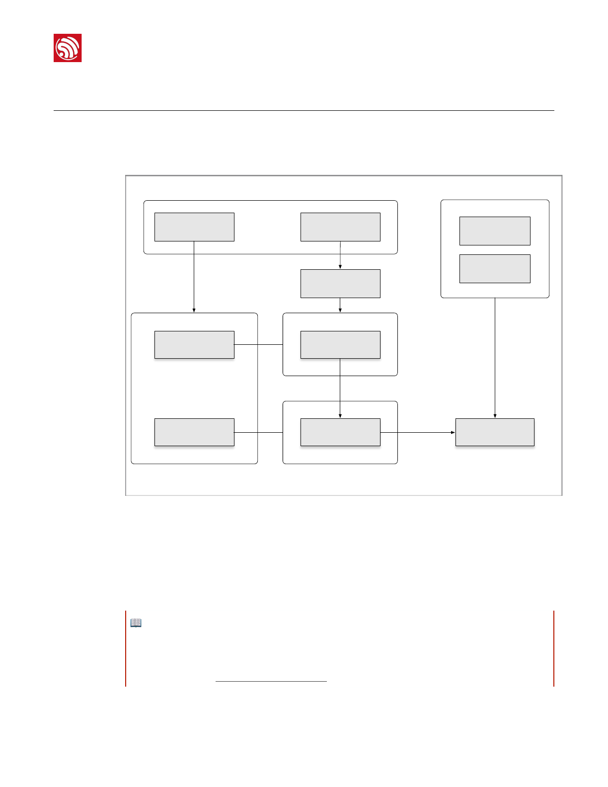
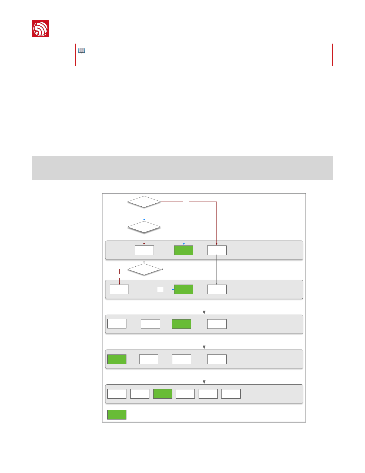
Figure 1-1 shows the overall procedure of the SDK compilation.
!
Figure 1-1 Procedure Overview
1.2. ESP8266 HDK
The ESP8266 HDK (Hardware Development Kit) includes the chip—ESP8266EX, the
module—ESP-WROOM-02U and the development board—ESP-LAUNCHER. Users can
download the pre-compiled firmware using ESP-WROOM-02U or ESP-LAUNCHER.
ESP8266 HDK
Chapter 6.
Downloading the Firmware
Chapter 5.
Compiling the SDK
ESP8266 FW
ESP8266 SDK
ESP8266 Toolkit
Compiler
Tool Download
Tool Download ESP-WROOM-02
SDK Download
Chapter 4. Flash
Map
Chapter 3. Preparing the Software
ESP-LAUNCHER
Chapter 2. Preparing the Hardware
📖 Notes:
•If users use other development boards or modules that integrate ESP8266EX, please use the
development firmware provided by the corresponding manufacturers.
•If users would like to purchase ESP-WROOM-02U or ESP-LAUNCHER, please visit Espressif’s official
online store at: https://espressif.taobao.com,
Espressif
!/331
2017.11

!
1. Overview
1.3. ESP8266 SDK
The ESP8266 Software Development Kit (SDK) is an Internet of Things (IoT) application
development platform developed by Espressif for developers. It includes such examples of
application development as Smart Lights and Smart Plugs.
Depending on whether they are based on an operating system (OS), SDKs can be
categorized into two types: Non-OS SDK and RTOS SDK.
1.3.1. Non-OS SDK
Non-OS SDK is not based on an operating system. It supports the compilation of
IOT_Demo and AT commands. Non-OS SDK uses timers and callbacks as the main way to
perform various functions such as nested events and functions triggered by certain
conditions. Non-OS SDK uses the espconn network interface; users need to develop their
software according to usage rules of the espconn interface.
1.3.2. RTOS SDK
RTOS SDK is based on FreeRTOS, open-source software development on Github.
•The FreeRTOS SDK is based on FreeRTOS , a multi-tasking OS. Users can use
standard interfaces to realize resource management, recycling operations, execution
delays, inter-task messaging and synchronization, and other task-oriented process
design approaches. For the specifics of interface methods, please refer to the official
website of FreeRTOS or USING THE FreeRTOS REAL TIME KERNEL—A Practical
Guide
•The network operation interface in RTOS SDK is the standard lwIP API. RTOS SDK
provides a package which enables a BSD Socket API interface. Users can directly
use the socket API to develop software applications; and port to ESP8266 other
applications from other platforms using the socket API, effectively reducing the
learning costs arising from switching platforms.
•RTOS SDK introduces cJSON library whose functions make it easier to parse JSON
packets.
•RTOS is compatible with non-OS SDK in Wi-Fi interfaces, SmartConfig interfaces,
Sniffer related interfaces, system interfaces, timer interfaces, FOTA interfaces and
peripheral driver interfaces, but does not support AT implementation.
1.4. ESP8266 FW
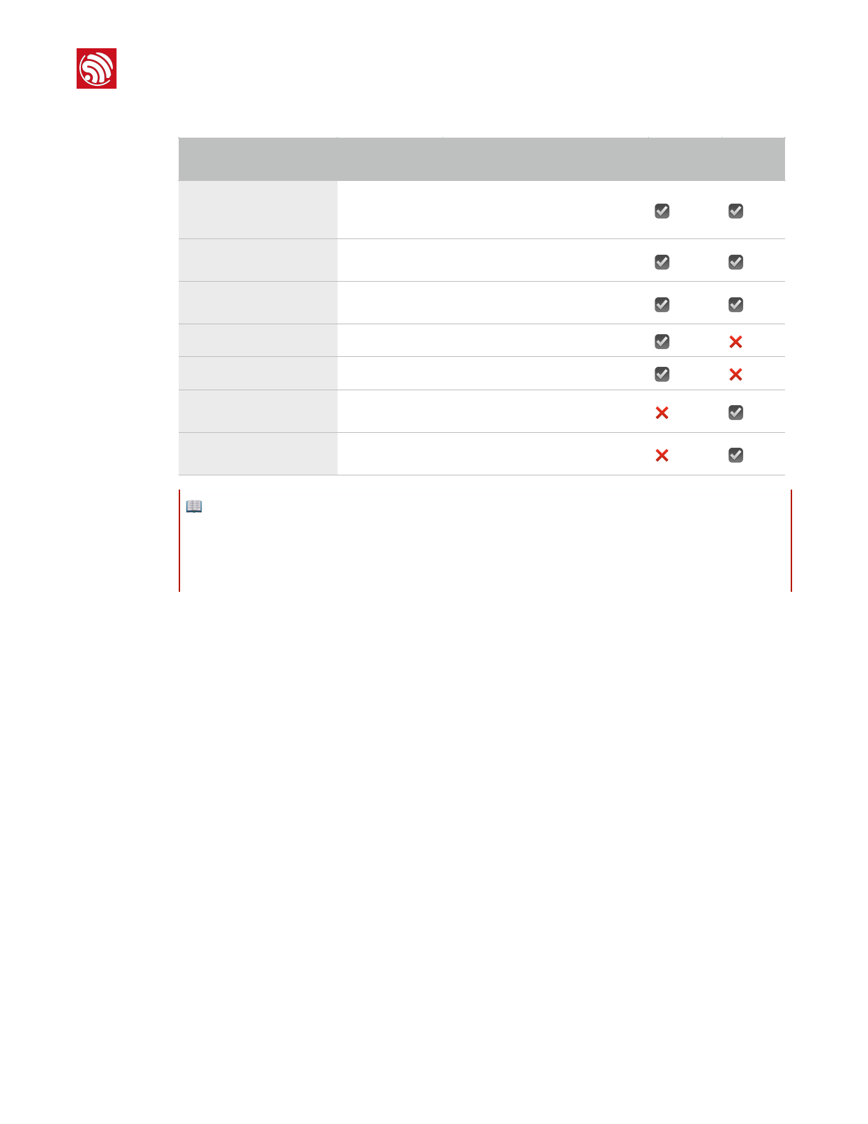
ESP8266 FW (Firmware) has been provided in binary format files (.BIN) that can be
downloaded directly to the HDK. Users can choose between Over-The-Air (OTA) and non-
OTA firmware. For detailed information, please refer to Table 1-1.
Espressif
!/332
2017.11
!
1. Overview
1.5. ESP8266 Toolkit
1.5.1. Compiler
Linux OS is required to compile the ESP8266 SDK. When using Windows OS, we
recommend VirtualBox as the virtual machine for ESP8266. In order to simplify the
compilation procedure, we have installed the compiling tools on the virtual machine. Users
can directly compile the ESP8266 SDK by importing the ESP8266 compiler (OVA image)
into the virtual machine.
1.5.2. Firmware Download Tool
The ESP8266 DOWNLOAD TOOL is the official firmware download tool developed by
Espressif. Users can download multiple binaries to the SPI Flash of the ESP8266 mother
board (ESP-LAUNCHER or ESP-WROOM-02U) at the same time according to the actual
compilation mode and flash size.
1.5.3. Serial Port Debug Tool
The serial port debug tool can be used to directly communicate with the ESP8266 module
over a standard RS-232 port. For PCs that do not have a physical serial port, a virtual com
port (USB-to-serial converter) can be used.
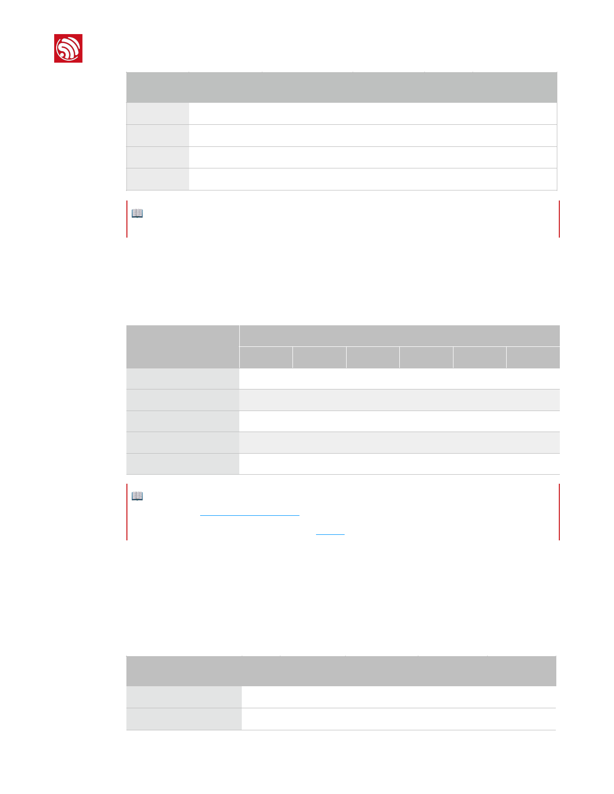
Table 1-1. ESP8266 FW
Binaries
Compulsory or
optional
Description
Non-OTA
OTA
master_device_key.bin
Optional
Users can apply for it from
Espressif Cloud to get Espressif
Cloud service.
☑
☑
esp_init_data_default.bin
Compulsory
Default system parameters
provided in SDK.
☑
☑
blank.bin
Compulsory
Default system parameters
provided in SDK.
☑
☑
eagle.flash.bin
Compulsory
Main program compiled from SDK.
☑
❌
eagle.irom0text.bin
Compulsory
Main program compiled from SDK.
☑
❌
user1.bin
Compulsory for
first usage.
Main program compiled from SDK.
❌
☑
user2.bin
Used in firmware
upgrade.
Main program compiled from SDK.
❌
☑
📖 Notes:
•For the contents of SDK, please refer to Chapter 3, "Preparing the Software".
•For SDK compilation, please refer to Chapter 5, "Compiling the SDK".
•For the addresses of binaries in the flash, please refer to Chapter 4, "Flash Maps".
Espressif
!/333
2017.11

!
1. Overview
Users may directly input commands into the terminal and view or record responses in real
time.
📖 Note:
We recommend CoolTerm (for Windows and Mac OS) and Minicom (for Linux OS) as the serial port debug
tool.
Espressif
!/334
2017.11
!
2. Preparing the Hardware
2. Preparing the Hardware
Depending on whether the ESP-LAUNCHER or the ESP-WROOM-02U is used, users will
need either of the hardware mentioned in Table 2-1 below:
2.1. ESP-LAUNCHER
1. Connect PC to the USB-UART interface of ESP-LAUNCHER using the USB cable.
2. Set ESP-LAUNCHER to download mode.
3. Connect the USB-to-TTL converter to the PC.
4. Power on ESP-LAUNCHER by sliding the Power Switch towards the inner side.
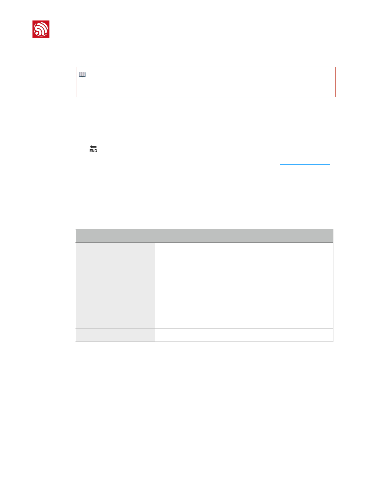
Table 2-1. Hardware Preparations
ESP-LAUNCHER
ESP-WROOM-02U
• 1 × ESP-LAUNCHER
• 1 × USB cable
OR
• 1 × ESP-WROOM-02U
• 1 × USB-to-TTL converter (FT232R recommended)
• 6 × Dupont lines
• 1 × soldering tool suite
1 × PC with pre-installed Windows OS
⚠ Notice:
The ESP8266 Wi-Fi module needs a 3.3V power supply and may draw a minimum current of 500 mA.
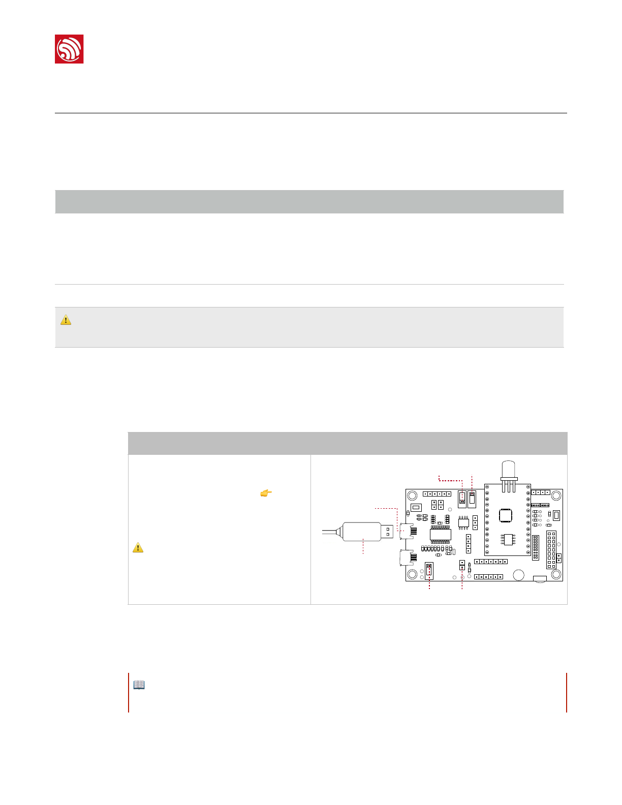
Steps
Result
•Slide Power Switch towards the outer
side as the figure on the right 👉 shows.
•Slide GPIO0 Control towards the inner
side to enable ESP-LAUNCHER's
download mode.
⚠ Notice:
J82 must be shorted by a jumper, otherwise
code cannot be downloaded to the board.
!
1
1
GPIO0 Control
Power Switch
USB-serial Cable
USB-UART
Chip Switch
J82
📖 Note:
Make sure that the proper driver for the USB-to-TTL converter is installed and recognized by the PC.
Espressif
!/!5 33
2017.11
!
2. Preparing the Hardware
5. Power on the chip by sliding the Chip Switch towards the outer side.
6. Download firmware to flash with the ESP8266 DOWNLOAD TOOL.
7. After downloading, slide the GPIO0 Control towards the outer side to enable ESP-
LAUNCHER's working mode.
8. Power on the chip again with the Chip Switch and the chip will read and run programs
from the flash.
——🔚
For more information on the ESP-LAUNCHER hardware, please refer to ESP8266 System
Description.
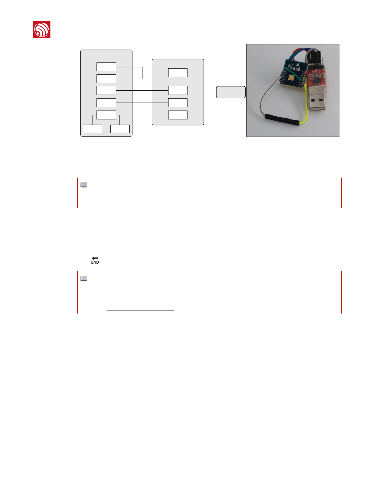
2.2. ESP-WROOM-02U
1. Lead out the pins of the ESP-WROOM-02U, as shown in Table 2-2.
2. Connect ESP-WROOM-02U to the USB-to-TTL converter, using Dupont lines, as
shown in Figure 2-1.
📖 Note:
On how to download firmware, please refer to Chapter 4, "Flash Map" and Chapter 6, "Downloading the
Firmware".
Table 2-2. ESP-WROOM-02U Pins
Pin
Pin status
EN
Pull up
3V3
3.3V power supply (VDD)
IO15
Pull down
IO0
UART download: pull down;
Flash boot: floating/pull up
GND
GND
RXD
Receive-end in UART download
TXD
Transmit-end in UART download; floating/pull up
Espressif
!/!6 33
2017.11
!
2. Preparing the Hardware
! !
Figure 2-1. ESP-WROOM-02U Download Mode
3. Connect the USB-to-TTL converter to the PC.
4. Download firmware to flash with the ESP8266 DOWNLOAD TOOL.
5. After downloading, switch ESP-WROOM-02U to working mode."
Set IO0 as floating or pull-up.
6. Power on ESP-LAUNCHER again and the chip will read and run programs from the
flash.
——🔚
EN
3V3
ESP-WROOM-02
3V3
TXD
RXDTXD
RXD
GNDGND
IO15 IO0
USB-to-TTL converter
PC
📖 Note:
On how to download firmware, please refer to Chapter 4, "Flash Maps" and Chapter 6, "Downloading the
Firmware".
📖 Notes:
•IO0 is an internal pull-up pin.
•For more information on ESP-WROOM-02U hardware, please refer to ESP8266 System Description
and ESP-WROOM-02 Datasheet.
Espressif
!/!7 33
2017.11
!
3. Preparing the Software
3. Preparing the Software
3.1. Non-OS SDK
Users can download the non-OS SDK (including application examples) from:"
http://www.espressif.com/en/support/download/sdks-demos?
keys=&field_type_tid%5B%5D=14.
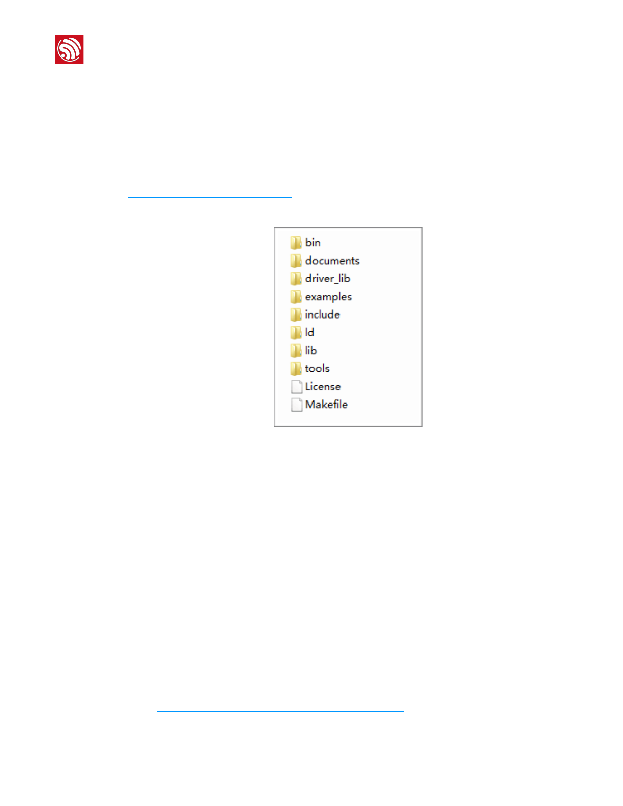
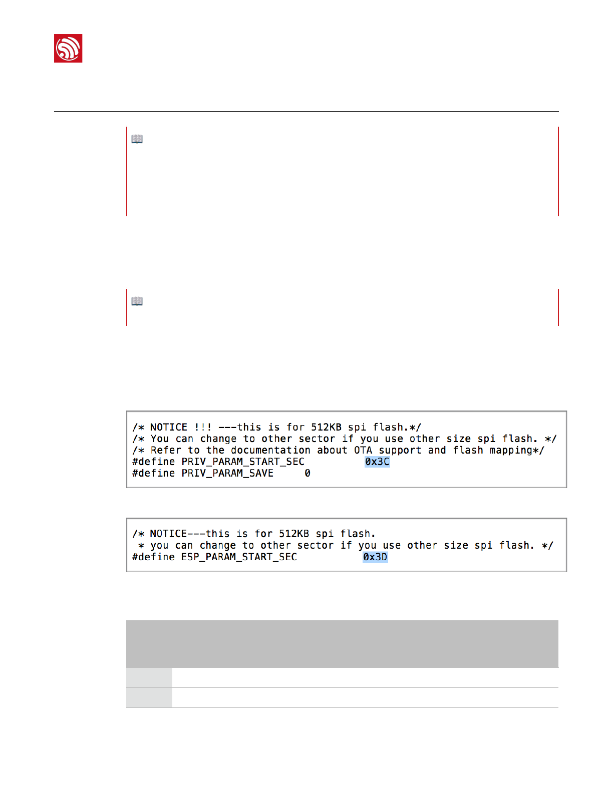
Figure 3-1 shows the directory structure of the non-OS SDK.
!
Figure 3-1. Non-OS SDK Directory Structure
•bin: compiled binaries to be downloaded directly into the flash.
•documents: SDK-related documents or links.
•driver_lib: library files that drive peripherals, such as UART, I2C and GPIO.
•examples: sample codes for secondary development, for example, IoT Demo.
•include: header files pre-installed in SDK. The files contain relevant API functions and
other macro definitions. Users do not need to modify them.
•ld: linker scripts. We suggest users not modifying them without any specific reasons.
•lib: library files provided in SDK.
•tools: tools needed for compiling binaries. Users do not need to modify them.
3.2. RTOS SDK
Users can download RTOS SDK and its application examples (ESP8266_IOT_PLATFORM)
from:
•RTOS SDK"
https://github.com/espressif/ESP8266_RTOS_SDK
Espressif
!/!8 33
2017.11
!
3. Preparing the Software
•ESP8266_IOT_PLATFORM"
https://github.com/espressif/ESP8266_IOT_PLATFORM
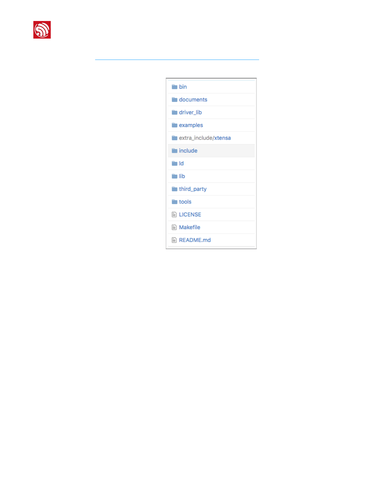
Table 3-2 shows the directory structure of the RTOS SDK.
!
Figure 3-2. RTOS SDK Directory Structure
•bin: boot and initialization firmware.
•documents: ESP8266_RTOS_SDK files.
•driver_lib: sample codes of drivers.
•examples: sample codes for Espressif’s application programs.
-openssl_demo: sample codes of the openssl API function.
-project_template: sample codes of project templates.
-smart_config: sample codes of SmartConfig.
-spiffs_test: sample codes of the spiffs file system function.
-websocket_demo: sample codes of web socket.
•include: header files of ESP8266_RTOS_SDK, including software interfaces and
macro functions for users to use.
•ld: link files used when compiling; users do not need to modify them.
•lib: library file of ESP8266_RTOS_SDK.
•third_party: third-party library of Espressif’s open-source codes, currently including
free RTOS, JSON, lwIP, mbedTLS, noPoll, OpenSSL, spiffs, and SSL.
•tools: tools needed for compiling binaries; users do not need to modify them.
Espressif
!/!9 33
2017.11
!
3. Preparing the Software
3.3. ESP8266 Toolkit
3.3.1. Compiler
Please download VirtualBox from: https://www.virtualbox.org/wiki/Downloads.
Please download the compiler ESP8266_lubuntu_20141021.ova from:
http://downloads.espressif.com/FB/ESP8266_GCC.zip
📖 Note:
Please choose the right version of VirtualBox according to the host machine's OS.
Steps
Results
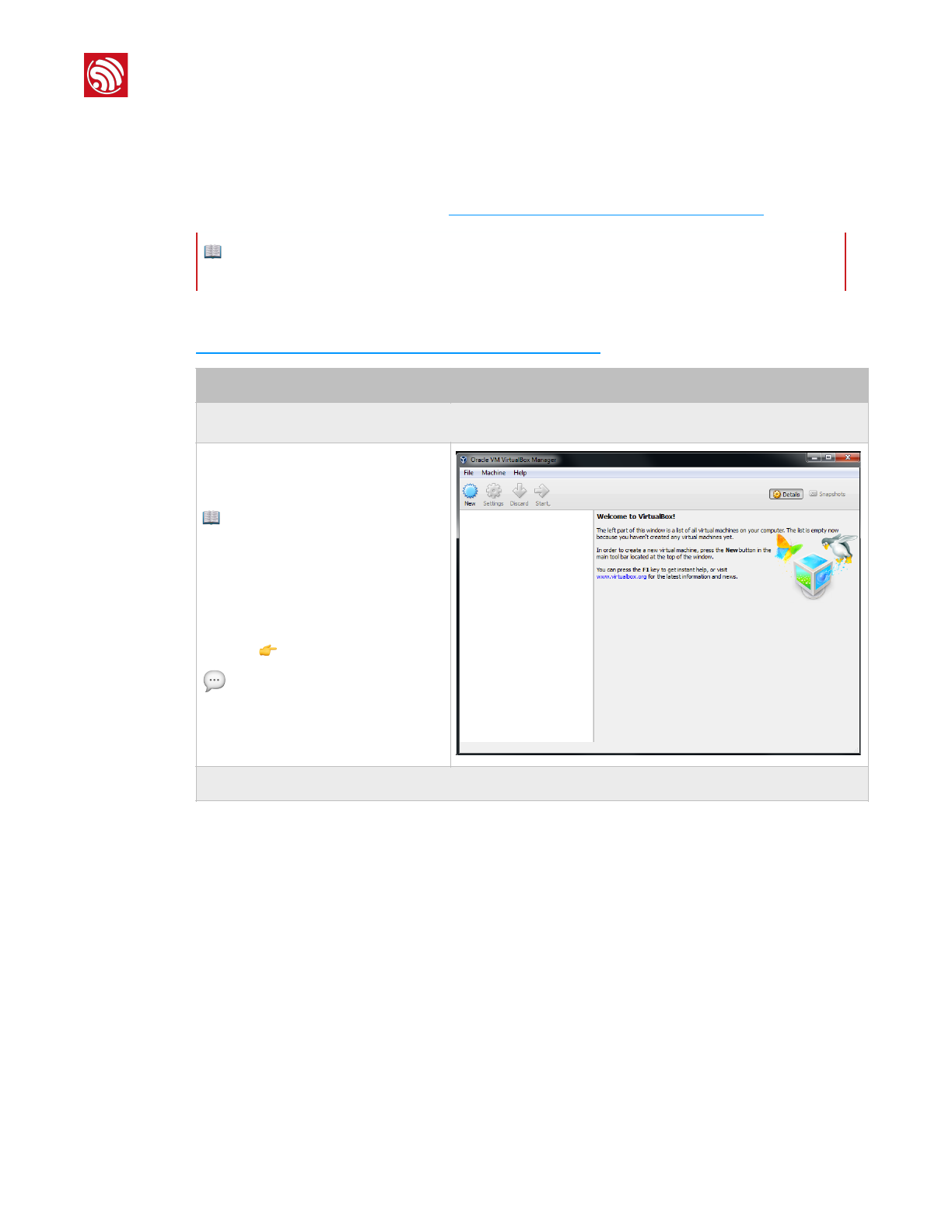
1. Start Windows OS and install the virtual machine.
•Double-click
VirtualBox-5.0.16-105871-Win.exe
and install VirtualBox.
📖 Note:
VirtualBox has different versions. We are
using Windows V.5.0.16 as an
example.
•Double-click Oracle VM
VirtualBox.exe to run the program,
and the system will show the main
menu 👉.
💬Tip:
The ESP8266 virtual machine takes up
much space (memory). Please reserve
enough space for it.
2. Import the image file.
!
Espressif
!/!10 33
2017.11
!
3. Preparing the Software
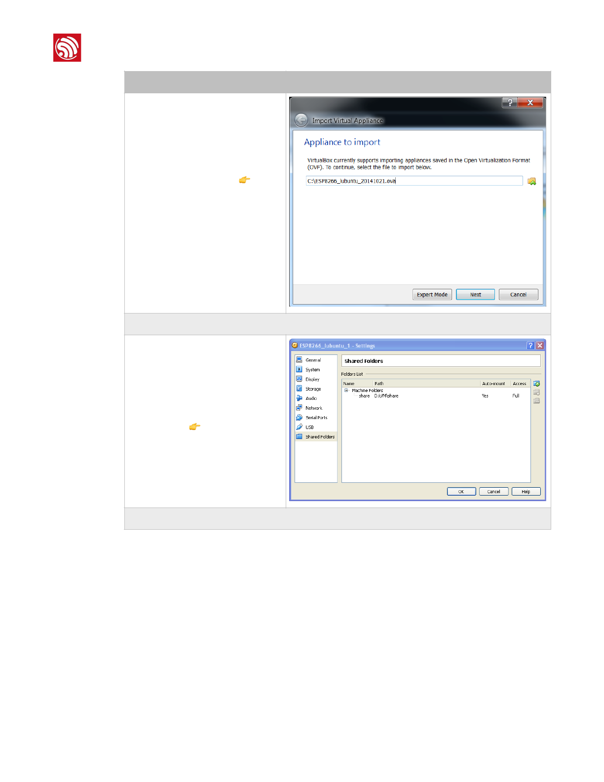
•Select File > Import Appliance, and
a dialog box will show up 👉.
•Select the image file to import, for
example, C:
\ESP8266_lubuntu_20141021.ova,
and click Next.
•Click Import to confirm the settings.
3. Create a shared folder.
•Create a new folder named D:
\VM\share.
•Select Machine > Settings >
Shared Folders…, and a dialog box
will show up 👉.
•Select the shared folder in Machine
Folders, for example, D:\VM\share.
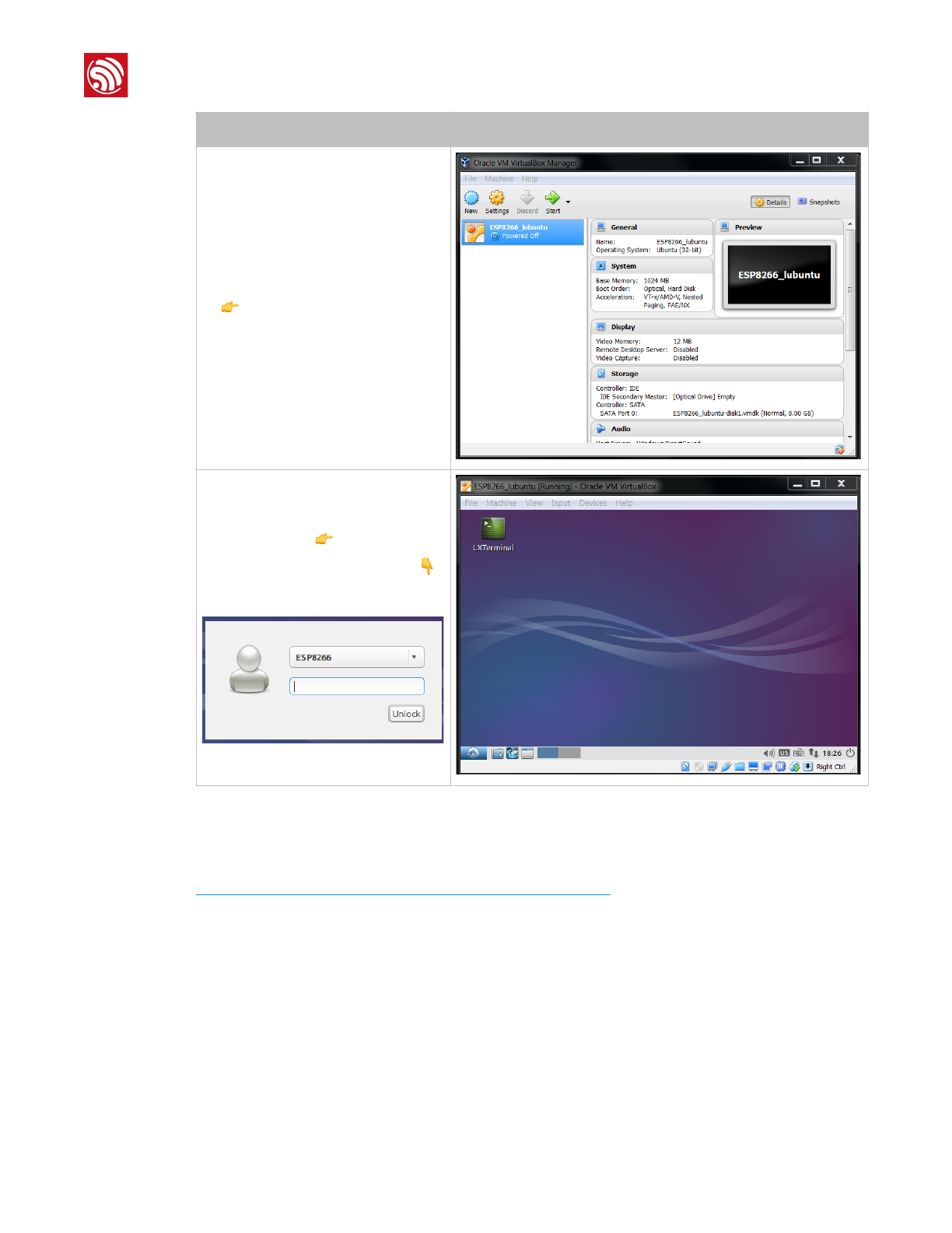
4. Run the virtual machine.
Steps
Results
Espressif
!/!11 33
2017.11
!
3. Preparing the Software
3.3.2. Firmware Download Tool
Please download the ESP8266 DOWNLOAD TOOL from:
http://www.espressif.com/support/download/other-tools.
•After importing, a virtual machine
named ESP8266_lubuntu shows up
👉.
•Double-click ESP8266_lubuntu or
Start to run the virtual machine.
Steps
Results
•The system shows the ESP8266
virtual machine 👉.
•If a dialog box like the one below👇
shows up, please enter the
password: espressif.
!
Espressif
!/!12 33
2017.11
!
4. Flash Maps
4. Flash Maps
This chapter provides the flash maps for OTA firmware and non-OTA firmware in flash
memories with a different capacity. Users can modify the map as needed.
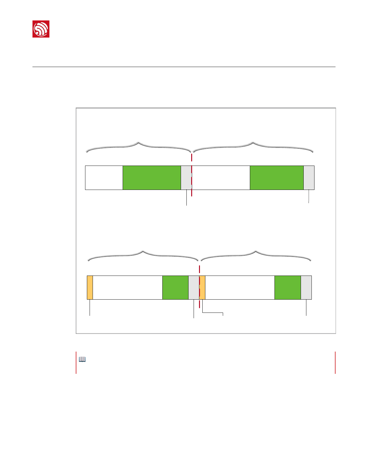
Figure 4-1 shows the flash maps for the two different types of firmware.
!
Figure 4-1. Flash Maps
•System Program: this area stores the firmware necessary for the system to run.
•User Data: If system data do not take up all the flash memory, the remaining area can
be used to store user data.
•User Param: Users can define the address. In IOT_Demo, the four sectors starting from
0x3C000 are defined as the user parameter area. Users can define any available
address for this area.
System Program
eagle.flash.bin User Data System Program
eagle.irom0text.bin User Data
User Param
master_device_key.bin
System Param (16 kB)
blank.bin
esp_init_data_default.bin
System Program
1.bin User Data
User Param
master_device_key.bin
System Param (16 kB)
blank.bin
esp_init_data_default.bin
System Program
2.bin User Data
Partition 1 Partition 2
Partition 1 Partition 2
Boot Data Reserved
Non-FOTA
FOTA
📖 Note:
For ESP8266 firmware, please refer to Section 1.3, "ESP8266 FW".
Espressif
!/!13 33
2017.11
!
4. Flash Maps
-master_device_key.bin: In IOT_Demo, it is located in the third sector of user
parameter area.
•System Param: this area contains the last four sectors of the flash.
-blank.bin: the download address is the second-to-last sector in the flash.
-esp_init_data_default.bin: the download address is the fourth-to-last sector of
flash.
•Boot Data: It is located in Partition 1 of OTA firmware, and stores OTA-related data.
•Reserved: It is a reserved area in Partition 2 of OTA firmware, corresponding to the
Boot data area in Partition 1 of OTA firmware.
4.1. Non-OTA
4.1.1. Flash Map
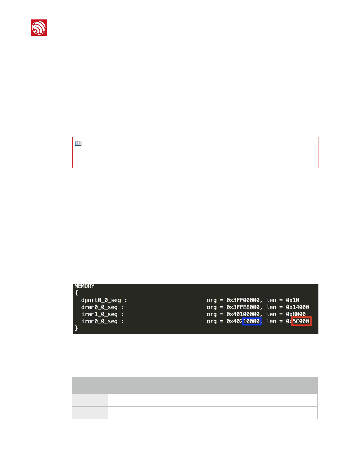
For flash memories with different capacity levels, the storage space of eagle.irom0text.bin
is limited. Users can change the limit by modifying ESP8266_NONOS_SDK/ld/
eagle.app.v6.ld.
Users can modify the len field in irom0_0_seg, as shown in Figure 4-2 (red rectangle).
The location of irom0.text varies across different versions of SDK. Users must consult the
eagle.app.v6.ld file and ensure that they are downloading eagle.irom0.text.bin to the
correct offset in the flash. The address in the blue rectangle marks the location of
eagle.irom0.text.bin in the flash.
!
Figure 4-2. Location for irom0.text
Table 4-1 shows the storage limits of eagle.irom0text.bin with different len values.
📖 Notes:
•Each sector of the flash is 4 KB.
•For detailed download addresses, please refer to the following sections..
Table 4-1. Non-OTA Flash Map (unit: KB)
Flash
capacity
eagle.flash.bin
eagle.irom0text.bin
User data
len
User/System
Param
512
≤ 64
≤ 240
≥ 176
0x3C000
16
1024
≤ 64
≤ 752
≥ 176
0xBC000
16
Espressif
!/!14 33
2017.11
!
4. Flash Maps
4.1.2. Download Addresses
Table 4-2 lists the download addresses for non-OTA firmware.
4.2. OTA Firmware
4.2.1. Flash Map
Table 4-3 lists the download addresses for the OTA firmware.
2048
≤ 64
≤ 768
≥ 176
0xC0000
16
4096
≤ 64
≤ 768
≥ 176
0xC0000
16
8192
≤ 64
≤ 768
≥ 176
0xC0000
16
16*1024
≤ 64
≤ 768
≥ 176
0xC0000
16
Flash
capacity
eagle.flash.bin
eagle.irom0text.bin
User data
len
User/System
Param
📖 Note:
ESP8266 presently only supports a System Param area of up to 1024 KB.
Table 4-2. Download Address for Non-OTA Firmware (unit: KB)
Binaries
Download addresses in flash with different capacities
512
1024
2048
4096
8192
16*1024
master_device_key.bin
0x3E000
esp_init_data_default.bin
0x7C000
0xFC000
0x1FC000
0x3FC000
0x7FC000
0xFFC000
blank.bin
0x7E000
0xFE000
0x1FE000
0x3FE000
0x7FE000
0xFFE000
eagle.flash.bin
0x00000
eagle.irom0text.bin
0x10000
📖 Notes:
•In general, ESP Flash Download Tool can be used to download firmware into flash.
•But for 8 MB or 16 MB flash, please use esptool instead.
Table 4-3. OTA Flash Map (unit: KB)
Flash capacity
boot
user1.bin
user2.bin
User/System
Param
User data
512
4
≤ 236
≤ 236
16
≥ 0
1024
4
≤ 492
≤ 492
16
≥ 0
Espressif
!/!15 33
2017.11
!
4. Flash Maps
4.2.2. Download Addresses
Table 4-4 lists the download addresses for the OTA firmware.
2048 (Partition 1 = 512)
4
≤ 492
≤ 492
16
≥ 1024
2048 (Partition 1 = 1024)
4
≤ 1004
≤ 1004
16
≥ 0
4096 (Partition 1 = 512)
4
≤ 492
≤ 492
16
≥ 3072
4096 (Partition 1 = 1024)
4
≤ 1004
≤ 1004
16
≥ 2048
8192 (Partition 1 = 1024)
4
≤ 1004
≤ 1004
16
≥ 6144
16384 (Partition 1 = 1024)
4
≤ 1004
≤ 1004
16
≥ 14336
Flash capacity
boot
user1.bin
user2.bin
User/System
Param
User data
Table 4-4. Download Addresses for OTA Firmware (unit: KB)
Binaries
Download addresses in flash with different capacities
512
1024
2048
4096
8192
16384
512+512
1024+102
4
512+512
1024+1024
1024+1024
1024+1024
master_device_key
.bin
0x3E000
0x7E000
0x7E000
0xFE000
0x7E000
0xFE000
0xFE000
0xFE000
esp_init_data
_default.bin
0x7C000
0xFC000
0x1FC000
0x3FC000
0x7FC000
0xFFC000
blank.bin
0x7E000
0xFE000
0x1FE000
0x3FE000
0x7FE000
0xFFE000
boot.bin
0x00000
user1.bin
0x01000
user2.bin
0x41000
0x81000
0x81000
0x101000
0x81000
0x101000
0x101000
0x101000
📖 Notes:
•In general, ESP Flash Download Tool can be used to download firmware into flash.
•But for 8 MB or 16 MB flash, please use esptool instead.
•For OTA firmware, users do not need to download user2.bin, but upgrade the firmware via the cloud
server.
•For details on the functional description of OTA firmware, please refer to ESP8266 FOTA Guide.
Espressif
!/!16 33
2017.11
!
5. Compiling the SDK
5. Compiling the SDK
5.1. Preparations
5.1.1. Modifying SDK Files
1. Start Windows OS.
2. Modify files in ESP8266_NONOS_SDK/examples/IoT_Demo/include according to the
flash map.
•Modify #definePRIV_PARAM_START_SEC in user_light.h and user_plug.h.
!
•Modify #defineESP_PARAM_START_SEC in user_esp_platform.h.
!
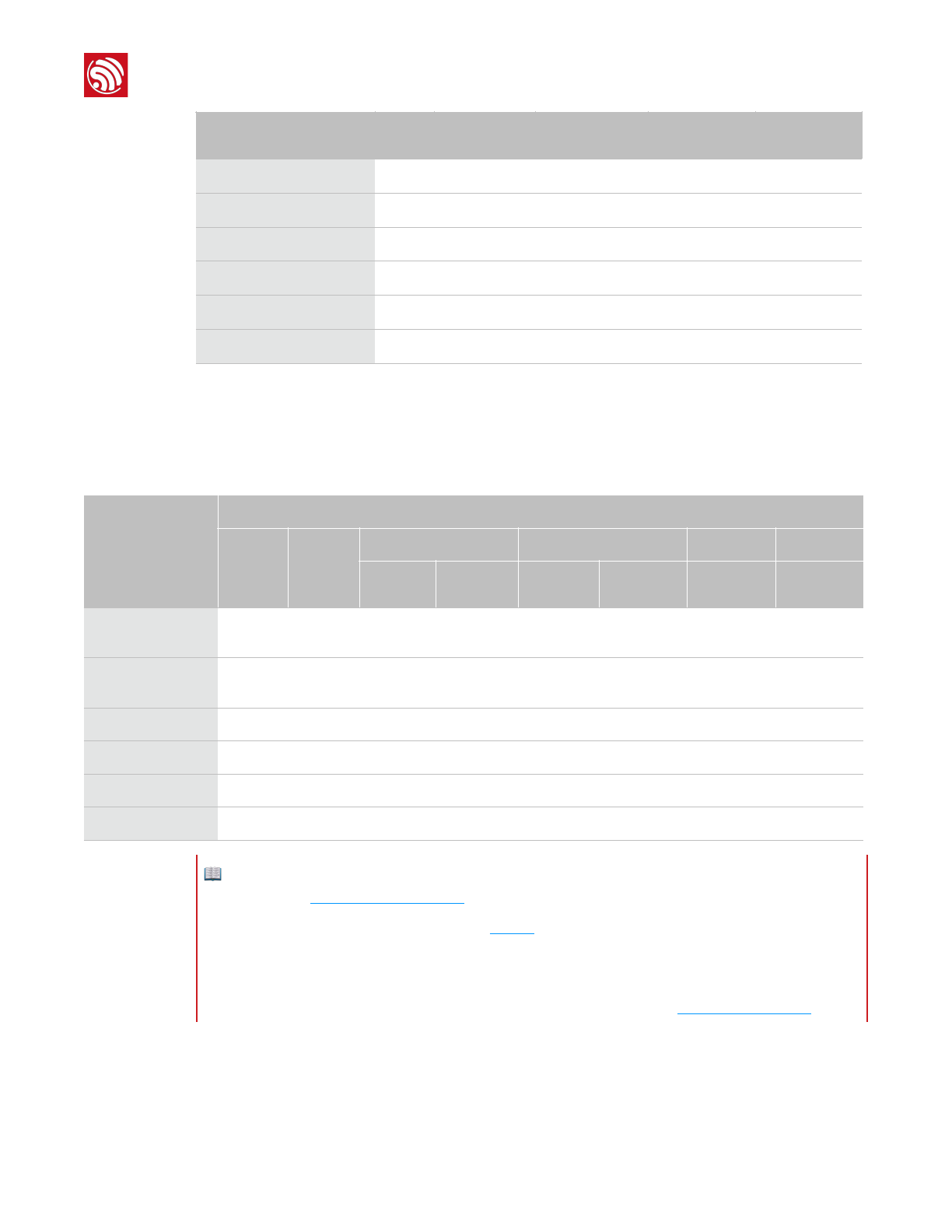
Table 5-1 lists the modified values.
📖 Notes:
•This chapter demonstrates how to compile the SDK by taking ESP8266_NONOS_SDK/examples/
IoT_Demo as an example.
•IoT_Demo defines three types of devices, i.e., LIGHT_DEVICE, PLUG_DEVICE and SENSOR_DEVICE
in examples>IoT_Demo/include/user_config.h. Users can only configure one device at a time. The
default device for configuration is LIGHT_DEVICE.
📖 Note:
Users need to modify the SDK files if using the OTA firmware.
Table 5-1. Modify the Field Values in the "include" File (unit: kB)
Default
value
(512)
Modified values
512
1024
2048
(512+512)
2048
(1024+1024)
4096
(512+512)
4096
(1024+1024)
8192
(1024+1024)
16384
(1024+1024)
0x3C
-
0x7C
0x7C
0xFC
0x7C
0xFC
0xFC
0xFC
0x3D
-
0x7D
0x7D
0xFD
0x7D
0xFD
0xFD
0xFD
Espressif
!/!17 33
2017.11
!
5. Compiling the SDK
5.1.2. Downloading SDK Files
1. Start Linux OS.
2. Run LXTerminal on the desktop of the virtual machine.
3. Copy the files to be compiled to the shared folder.
4. Download shared directory.
5. Set the variable PATH to point to SDK and binaries.
exportSDK_PATH=~/Share/ESP8266_RTOS_SDK
exportBIN_PATH=~/Share/ESP8266_RTOS_SDK/bin
📖 Note:
Users need not modify the SDK files if using a 512-KB flash.
Steps
Results
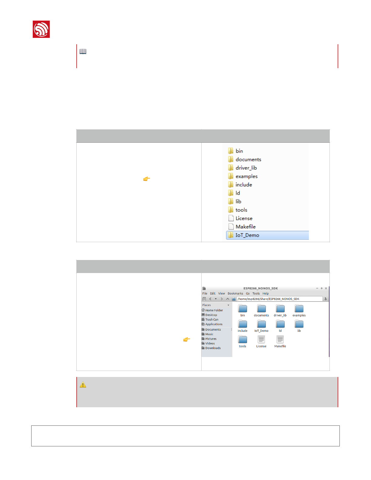
•Copy ESP8266_NONOS_SDK folder to the
shared directory, for example, C:\VM\share.
•Copy IoT_Demo folder to C:
\VM\share\ESP8266_NONOS_SDK, as shown
in the figure on the right 👉.
Steps
Results
•Execute ./mount.sh.
•Input the password: espressif."
Downloading shared files is completed.
•Open the shared directory
ESP8266_NONOS_SDK in the virtual machine
and confirm whether the download has been
successful.
- If successful, the directory contains such
files as those in the figure on the right 👉.
- If not, the directory will be empty, and users
will need to go over this step again.
⚠ Notice:
If users use the RTOS SDK, please continue with the following steps; if use the non-OS SDK, please skip
Step 5.
Espressif
!/!18 33
2017.11
!
5. Compiling the SDK
5.2. Compilation
5.2.1. Compile ESP8266_NONOS_SDK_v0.9.5 and Later Versions
1. Switch to the /Share/ESP8266_NONOS_SDK/IoT_Demo directory in the terminal.
cd/home/esp8266/Share/ESP8266_NONOS_SDK/IoT_Demo
./gen_misc.sh
The system shows the following information:
gen_misc.shversion20150511
Pleasefollowbelowsteps(1-5)togeneratespecificbin(s):
2. Select the required options as shown in Figure 5-1.
!
Figure 5-1. Compile SDK
📖 Note:
Users can add it to .bashrc file, otherwise Step 5 needs to be repeated each time the compiler is restarted.
012
0
STEP 1: choose boot version
(0=boot_v1.1, 1=boot_v1.2+, 2=none)
enter(0/1/2, default 2)
STEP 2: choose bin generate
(0=eagle.flash.bin+eagle.irom0text.bin
, 1=user1.bin, 2=user2.bin)
enter (0/1/2, default 0)
FOTA? N
New
version?
Y
N
Y
First-time
usage?
2
N
1Y
01 2 3
STEP 3: choose spi speed
(0=20MHz, 1=26.7MHz, 2=40MHz, 3=80MHz)
enter (0/1/2/3, default 2)
0 1 2 3
STEP 4: choose spi mode
(0=QIO, 1=QOUT, 2=DIO, 3=DOUT)
enter (0/1/2/3, default 0)
0 2 3
STEP 5: choose spi size and map
0= 512KB( 256KB+ 256KB)
enter (0/2/3/4/5/6, default 0)
Choose as required
Choose as required
Choose as required
4 5 6
Example Option
Espressif
!/!19 33
2017.11

!
5. Compiling the SDK
3. After compilation, the generated binaries and the addresses in flash are shown as
follows:
Generateuser1.2048.new.3.binsuccessfullyinfolderbin/upgrade.
boot.bin------------>0x00000
user1.2048.new.3.bin--->0xSupportboot_v1.2and+
01000
!!!
−−🔚
5.2.2. ESP8266_NONOS_SDK_v0.9.4 and Earlier Versions
For ESP8266_NONOS_SDK_v0.9.4 and previous versions, the compilation process is as
follows:
1. Execute ./gen_misc_plus.sh 1 to generate user1.bin under the"
/ESP8266_NONOS_SDK/bin/upgrade path.
2. Execute makeclean to clear previous compilation data.
3. Execute ./gen_misc_plus.sh2 to generate user2.bin under the"
/ESP8266_NONOS_SDK/bin/upgrade path.
📖 Notes:
•The sample options are marked in green. Users can select the right options as needed.
•For OTA and non-OTA firmware, please refer to Section 1.4, "ESP8266 FW".
•Only sdk_v1.1.0 + boot 1.4 + flash download tool_v1.2 and higher versions support options 5 and 6 in
Step 5.
•After compiling user1.bin, execute makeclean first to clear the temporary files generated by the last
compilation, and then compile user2.bin.
•For the flash map in Step 5, please refer to Chapter 4, "Flash Maps".
📖 Note:
Users can open the /home/esp8266/Share/ESP8266_NONOS_SDK/bin directory and check the compiled
binaries.
📖 Note:
ESP8266_NONOS_SDK_v0.7 and earlier are non-OTA firmware.
Espressif
!/!20 33
2017.11
!
6. Downloading the Firmware
6. Downloading the Firmware
6.1. Download Procedure
1. Start Windows OS.
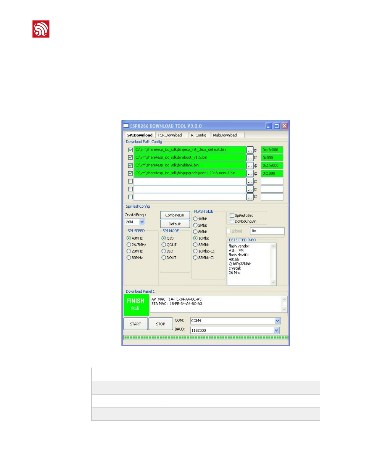
2. Double-click ESP_DOWNLOAD_TOOL.exe to open Flash tool.
Figure 6-1. ESP8266 DOWNLOAD TOOL—SPIDownload
SPIDownload
For SPI Flash download.
HSPIDownload
For HSPI Flash download.
RFConfig
RF initialization Configuration.
MutiDownload
For multi-mother boards download.
Espressif
!/!21 33
2017.11
!
6. Downloading the Firmware
3. Double-click ! in Download Path Config panel to select the binaries to be
downloaded. Set the corresponding download addresses in ADDR.
4. Configure SPIDownload.
📖 Note:
The binaries to be downloaded and the corresponding addresses vary with different SPI Flash sizes and
actual demands. For details, please refer to Chapter 4, "Flash Maps".
Table 6-1. SPIDownload Configuration
Items
Description
SPI FLASH CONFIG
CrystalFreq
Select the crystal frequency according to the crystal oscillator used.
CombineBin
Combine the selected binaries into target.bin with the address 0x0000.
Default
Set the SPI Flash to the default value.
SPI SPEED
Select SPI read/write speed with the maximum value of 80 MHz.
SPI MODE
Select SPI mode according to the SPI Flash used. If the flash is Dual SPI, select
DIO or DOUT. If the flash is Quad SPI, select DIO or DOUT.
⚠ Notice:
If ISSI Flash is used, please refer to Appendix, "Configure ISSI & MXIC Flash QIO
Mode".
FLASH SIZE
Select the flash size according to the flash type.
📖 Note:
16Mbit-C1 refers to 1024+1024 flash map and 32Mbit-C1 1024+1024 flash map
as well.
SpiAutoSet
We recommend not checking SpiAutoSet, but configuring the flash manually as
needed.
If users select SpiAutoSet, the binaries will be downloaded according to the
default flash map. The flash map of 16 Mbit and 32 Mbit will be 512 KByte + 512
KByte.
DoNotChgBin
•If users select DoNotChgBin, the flash working frequency, mode, and flash
map will be based on the configuration when compiling.
•If users do not select DoNotChgBin, the flash working frequency, mode, and
flash map will be defined by the final configuration of the compiler.
Download Panel
START
Click START to start download. When the download completes, FINISH will
appear in the green area on the left.
STOP
Click STOP to stop download.
MAC Address
If download is successful, the system will show the MAC addresses of ESP8266
STA and ESP8266 AP.
COM PORT
Select the actual COM port of ESP8266.
Espressif
!/!22 33
2017.11

!
6. Downloading the Firmware
5. After downloading, turn GPIO0 Control on ESP-LAUNCHER to the outer side and power
the board on to enable the working mode.
6.2. Check Log File
After downloading firmware, users can check the log printed in the terminal by using the
serial port debug tool.
Users need to configure the settings of the serial port debug tool, as follows:
6.2.1. ESP8266 IOT Demo
If users download ESP8266 IOT Demo firmware, the system in working mode will show the
initialization information including the SDK version, etc. “Finish” means the firmware works
properly.
SDKversion:X.X.X(e67da894)
IOTVERSION=v1.0.5t45772(a)
resetreason:0
PWMversion:00000003
mode:sta(18:fe:34:a4:8c:a3)+softAP(1a:fe:34:a4:8c:a3)
BAUDRATE
Select the baud rate of downloading. The default value is 115200.
Items
Description
SPI FLASH CONFIG
Table 6-2. Serial Port Debug Tool Configuration
Items
Configuration Description
Protocol
Serial port.
Port number
Set the port number according to the connected device.
Baud rate
The baud rate at which the device is running, related to the crystal oscillator.
•69120 (24 M crystal oscillator)
•74880 (26 M crystal oscillator)
•115200 (40 M crystal oscillator)
The ESP8266 AT example supports the baud rate of 115200 by default.
Users cannot modify it.
The ESP8266 IOT Demo example supports the baud rate of 74880. Users
can modify it.
Data bit
8
Calibration
None.
Flow control
None.
Espressif
!/!23 33
2017.11

!
6. Downloading the Firmware
addif0
addif1
dhcpserverstart:(ip:192.168.4.1,mask:255.255.255.0,gw:192.168.4.1)
bcn100
finish
6.2.2. ESP8266 AT
If users download the ESP8266 AT firmware, or the default firmware in ESP-LAUNCHER or
ESP-WROOM-02U, the system in working mode will display “Ready” at the end. Input
command “AT” in the terminal and the system will return “OK”, which means that the
firmware works properly.
6.3. Configuration of RF initialization (Optional)
Before downloading binaries to flash, users can modify the RF initialization settings in the
RF InitConfig tab. The newly-generated esp_init_data_setting.bin can be downloaded to
the flash instead of esp_init_data_default.bin. Users can configure both the options and
the parameters of the RF settings.
📖 Notes:
•The baud rate in AT firmware is configured as 115200 manually, however, the default baud rate of
ESP8266 is 74880, due to this discrepancy, the system initialization information will be displayed as
mojibake. It is a normal phenomenon as long as the system shows “Ready” at the end.
•For more information on AT commands, please refer to ESP8266 AT Instruction Set.
Espressif
!/!24 33
2017.11
!
6. Downloading the Firmware
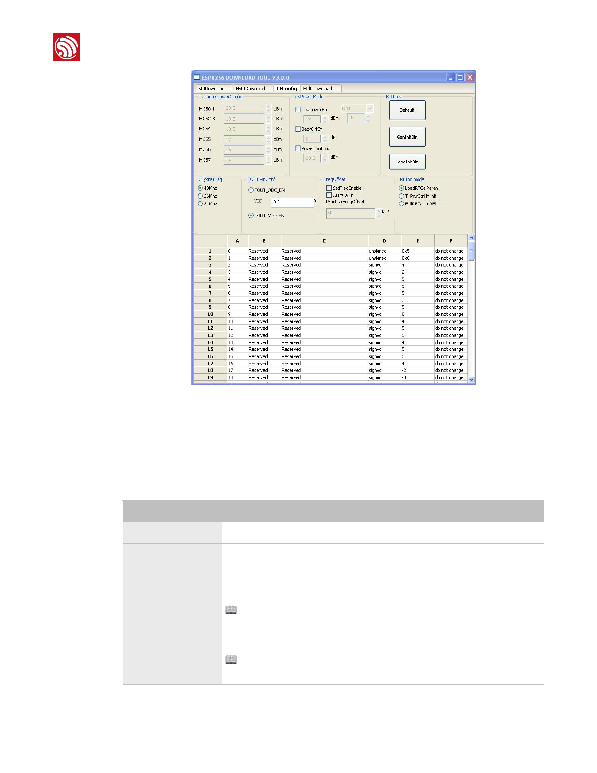
!
Figure 6-2. ESP8266 DOWNLOAD TOOL - RF InitConfig
6.3.1. Configuration of RF InitConfig Options
RF InitConfig options are listed in the upper part of Figure 6-2. Please refer to Table 6-3 for
a description of this configuration.
Table 6-3. Configuration of RF InitConfig Options
Items
Description
TxTargetPowerConfig
Users need not configure this. It varies with the options in LowPowerMode.
LowPowerMode
Configure the low power mode as required.
•LowPowerEn: enable low power mode, set a power value for all data rates.
•PowerLimtEn: set a limit for output power.
•BackOffEn: set backoff value for each data rate.
📖 Note:
Users cannot configure LowPowerEn and PowerLimtEn at the same time.
CrystalFreq
Select the crystal oscillator frequency according to the crystal oscillator used.
📖 Note:
If a different option is selected when downloading, it will override this configuration.
Espressif
!/!25 33
2017.11
!
6. Downloading the Firmware
6.3.2. Configuration of RF InitConfig Parameters
RF InitConfig parameters are listed in the lower part of Figure 6-2. The description of
parameters’ configuration is shown in Table 6-4.
TOUT PinConf
Configure the TOUT pin according to the actual TOUT pin status. We recommend
the default value.
•TOUT_ADC_EN: When the TOUT pin connects to an external circuit,
measure the external voltage (0V - 1V) through the internal ADC.
•TOUT_VDD_EN: When TOUT pin is left floating, measure VDD33 voltage
through uint16 system_get_vdd33(void).
⚠ Notice:
•Users cannot configure TOUT_ADC_EN and TOUT_VDD_EN at the same
time.
•When users use TOUT_ADC_EN, they need to input the actual voltage on
VDD3P3 pin 3 and pin 4.
FreqOffset
•SetFreqEnable: Set the frequency offset manually.
-PracticalFreqOffset: the option is valid when selecting SetFreqEnable.
•AutoCalEn: Set the frequency offset automatically.
RFInt mode
Users can select the RF initialization mode:
•LoadRFCalParam: During the RF initialization, RF data are loaded directly
from the flash without any calibration. It takes about 2 ms and the least initial
current.
•TxPwrCtrl in init: During the RF initialization, only Tx Power calibration will
be performed, and other data are loaded from flash. It takes about 20 ms
and small initial current.
•FullRFCal in RFInit: All calibrations are performed during the RF
initialization. It takes 200 ms and large initial current.
Items
Description
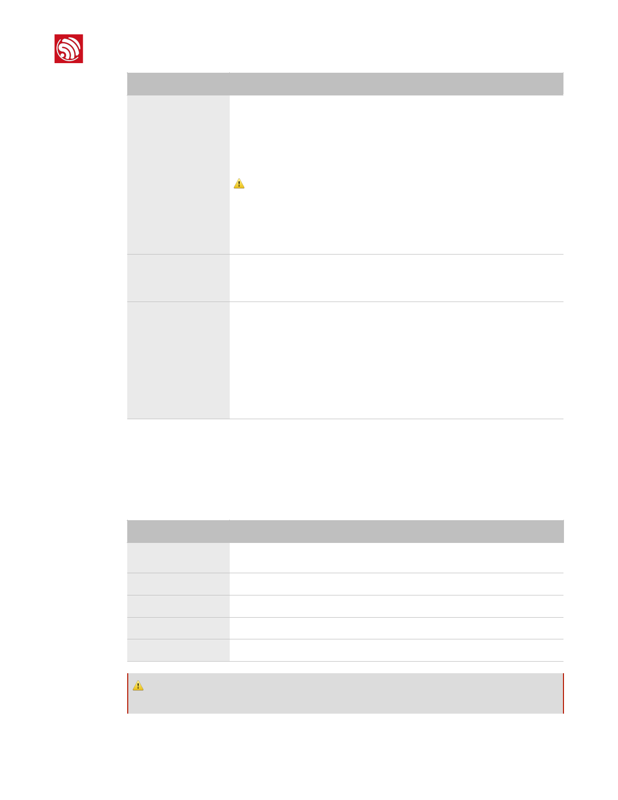
Table 6-4. Configuration of RF InitConfig Parameters
Items
Description
A
The byte in esp_init_data_setting.bin (0 ~ 127 byte). For example, A = 0
represents Byte 0 in esp_init_data_setting.bin.
B
The item name. Users cannot modify it if marked as Reserved.
C
The item name. Users cannot modify it if marked as Reserved.
D
Data types of configuration items, including unsigned and signed data types.
E
The hexadecimal value of a configuration item.
⚠ Notice:
Please do not modify the parameters marked as Reserved.
Espressif
!/!26 33
2017.11
!
6. Downloading the Firmware
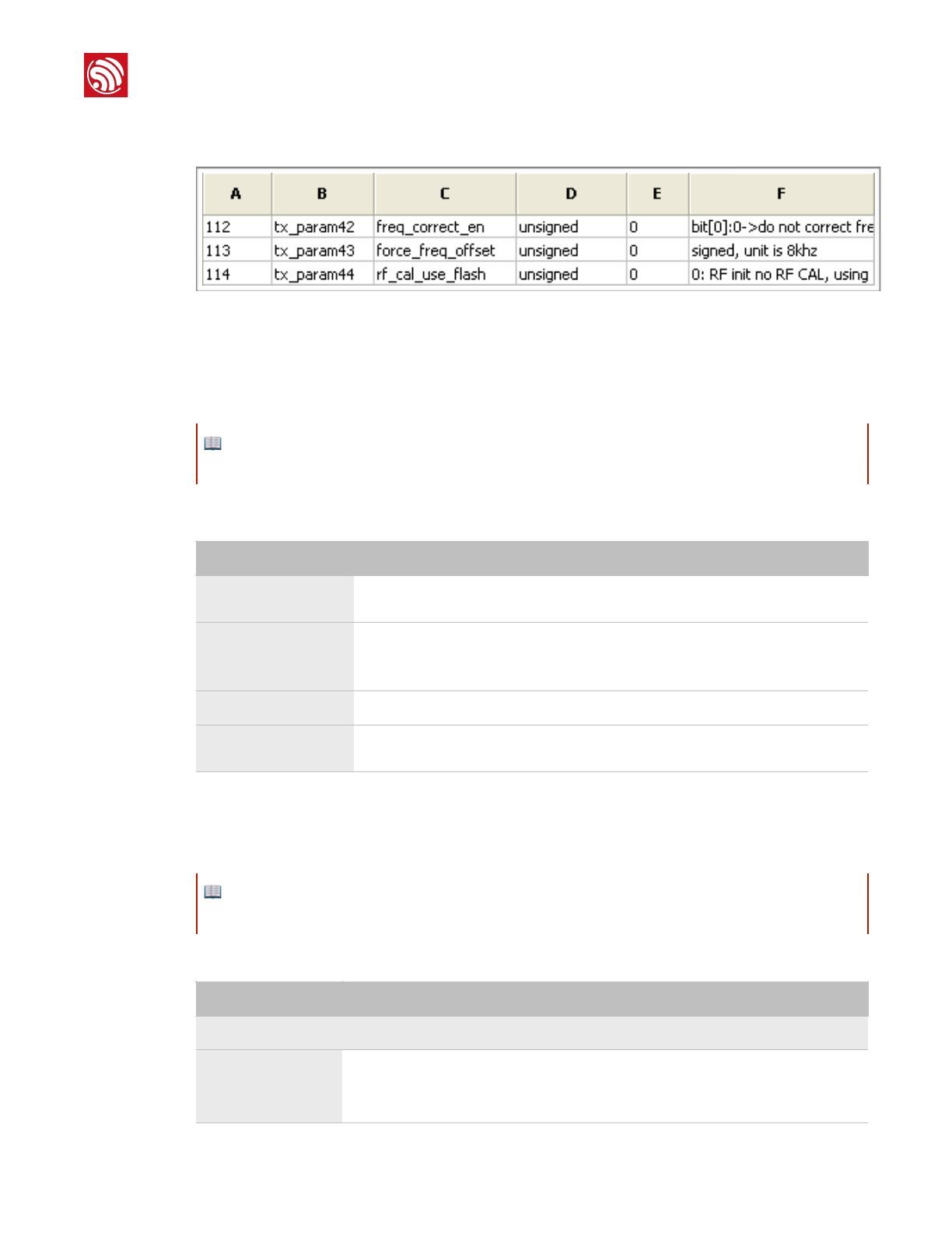
The following section introduces how to modify the 112 ~ 114 byte parameters. Figure 6-3 shows
the initial configuration.
!
Figure 6-3. 112 ~ 114 Byte Parameters
Modify the RF Initialization Parameters
Byte 114 is used to control THE RF initialization when ESP8266 is powered on. Table 6-5 provides
the parameter configuration.
Correct Frequency Offset
Byte 112 and byte 113 relate to the frequency offset correction. Table 6-6 provides the parameter
configuration.
📖 Note:
Supported by ESP8266_NONOS_SDK_V1.5.3 and ESP8266_RTOS_SDK_V1.3.0 and higher.
Table 6-5. Modify RF Initialization Parameters
Option
Description
byte 114 = 0
Only a VDD33 calibration is performed during the RF initialization. It takes about 2
ms and the least initial current.
byte 114 = 1
The default value is 1.
VDD33 and TX power calibrations are performed during the RF initialization. It takes
about 18 ms and small initial current.
byte 114 = 2
The same as when “ byte 114 = 0”.
byte 114 = 3
All calibrations are performed during the RF initialization. It takes about 200 ms and
large initial current.
📖 Note:
Supported by ESP8266_NONOS_SDK_V1.4.0 and ESP8266_RTOS_SDK_V1.3.0 and higher.
Table 6-6. Options for Frequency Offset Correction
Option
Description
The default value of byte 112 is 0.
bit 0
This bit is of the highest priority.
•bit 0 = 0: frequency offset cannot be corrected.
•bit 0 = 1: frequency offset can be corrected.
Espressif
!/!27 33
2017.11
!
6. Downloading the Firmware
6.3.3. Configuration Examples
The configuration of bytes 112 and 113 depends depends on users' specific needs. We
provide some examples below:
1. The module works at ambient temperature, and needs no correction of the
frequency offset.
•Set byte 112 = 0, byte 113 = 0.
2. The module works at ambient temperature and needs no automatic tracking and
correction of the frequency offset; yet the frequency offset is large. In this case, a
manual correction of the frequency offset is recommended.
•If the frequency offset is +160 KHz (at ambient temperature), users can set byte 112
= 0x07, byte 113 = (256 - 160/8) = 236 = 0xEC.
•If the frequency offset is -160 KHz (at ambient temperature), users can set byte 112 =
0x05, byte 113 = 160/8 = 20 = 0x14. This may effect the digital peripheral
performance, so we do not recommend it.
3. Applications, such as smart lights, work at a wide temperature range of -40 °C to
125 °C, and need to track and correct the frequency offset automatically. The
frequency offset at ambient temperature is small, so the initial offset correction
value is not needed.
•Set byte 112 = 0x03, byte 113 = 0.
bit 1
When value = 0, it means that the bbpll is 168 M. Both positive and negative
frequency offsets can be corrected.
However, this may effect the digital peripheral performance and, therefore, it is not
recommended.
When value = 1, it means that the bbpll is 160 M. Only the positive frequency offset
can be corrected.
{bit 3,bit 2}
When value = 0, it means that the chip will track and correct the frequency offset
automatically. The initial correction value is 0. When value = 1, it means that the chip
is manually programmed to change the frequency offset to that of byte 113, so the
chip will not track and correct the frequency offset automatically. When value = 2, it
means that the chip will track and correct the frequency offset automatically. The
initial correction value is that of byte 113.
The default value of byte 113 is 0.
113 byte
It is the value when the frequency offset is corrected manually or the initial correction
value in frequency tracking. The data type is sign int8, in multiples of 8 kHz.
Option
Description
The default value of byte 112 is 0.
Espressif
!/!28 33
2017.11

!
6. Downloading the Firmware
4. Applications, such as smart lights, work at a wide temperature range of -40 °C to
125 °C, and need to track and correct the frequency offset automatically. The
frequency offset at ambient temperature is large, so the initial offset correction
value is needed.
•If the frequency offset is +160 kHz (at ambient temperature), users can set byte 112
= 0x0B, byte 113 = (256 - 160/8) = 236 = 0xEC.
• If the frequency offset is -160 kHz (at ambient temperature), users can set byte 112
= 0x09, byte 113 = 160/8 = 20 = 0x14. But this may effect the digital peripheral
performance and needs substantive tests, so we do not recommend it.
We recommend Example 3.
When the configuration of RF initialization is done, click GenInitBin button to generate
esp_init_data_setting.bin.
In addition, users can click Default button to set the value of frequency offset to default, or
click LoadInitBin button to import a binary file for configuration.
Espressif
!/!29 33
2017.11
!
Appendix A
A. Appendix—Configuring ISSI &
MXIC Flash QIO Mode
When using QIO mode of ISSI flash or MXIC flash, users need to modify the first two bytes
in blank.bin, as shown in Table A-1. During initialization, ESP8266 will automatically check
the first two bytes and switch to QIO mode to read ISSI_FLASH or MXIC_FLASH. The
structure of blank.bin is shown below:
strcutboot_hdr{
charuser_bin:2;//low_bit
charboot_status:1;
charto_qio:1;
charreverse:4;
charversion:5;//lowbit
chartest_pass_flag:1;
chartest_start_flag:1;
charenhance_boot_flag:1;
}
⚠ Notice:
Choose DIO or DOUT mode when downloading, otherwise errors may occur. There is no need to modify
binaries in DIO or DOUT mode.
Table A-1. blank.bin Configuration
Option
Description
Without secondary boot loader
Modify to_qio to 0.
With secondary boot loader
Modify use_bin to 0 and to_qio to 0, as well. Modify version
according to the current boot version.
Example:
If users use the secondary boot_v1.5.bin, please modify the first two
bytes FF FF to F4 E5.
Espressif
!/!30 33
2017.11

!
Appendix B
B. Appendix—Learning
Resources
B.1. Must-Read Documents
•ESP8266EX Datasheet
Description: This document introduces the specifications of ESP8266EX, including an
overview of the features, protocols, technical parameters and applications. It also
describes the pin layout, as well as major functional modules integrated in ESP8266EX
(CPU, flash and memory, clock, radio, Wi-Fi, and low-power management). Additionally,
it provides descriptions of peripheral interfaces integrated on ESP8266EX, lists the
electrical data of ESP8266EX and illustrates the package details of ESP8266EX.
•ESP8266 Hardware Resources
Description: This zip package includes the manufacturing specifications of the ESP8266
board and its modules, manufacturing BOM and schematics.
•ESP8266 Non-OS SDK IoT_Demo Guide
Description: This documents provides simple demo implementations of three types of
smart devices: Smart Light, Smart Power Plug, and Sensor Device. It also introduces
the readers to curl toolkits, functions in LAN and WAN.
•ESP8266 RTOS SDK Programming Guide
Description: This document provides sample codes based on ESP8266_RTOS_SDK,
including basic examples, networking protocol examples and advanced examples.
•ESP8266 AT Command Examples
Description: This document introduces some specific examples of how to use Espressif
AT commands, including single connection as a TCP client, UDP transmission and
transparent transmission, and multiple connection as a TCP server.
•ESP8266 AT Instruction Set
Description: This document provides lists of AT commands based on
ESP8266_NONOS_SDK, including user-defined AT commands, basic AT commands,
Wi-Fi AT commands and TCP/IP-related AT commands. It also introduces the
downloading of AT firmware into flash.
•ESP8266 Non-OS SDK API Reference
Description: This document lists ESP8266_NONOS_SDK APIs, provides an overview of
ESP8266_NONOS_SDK and introduces the readers to system APIs, TCP/UDP APIs,
mesh APIs, application specific APIs, definitions and data structures, and APIs for
peripheral interfacing.
•ESP8266 RTOS SDK API Reference
Espressif
!/!31 33
2017.11

!
Appendix B
Description: This document lists ESP8266_RTOS_SDK APIs, including functions for Wi-
Fi related APIs, boot APIs, etc.
•FAQ
B.2. Must-Have Resources
•ESP8266 SDKs
Description: This webpage provides links to the latest version of ESP8266 SDK and the
older ones.
•RTOS Sample Code
Description: This webpage provides the sample code for the commonly used functions.
•Non-OS Sample Code
Description: This webpage provides the sample code for the commonly used functions.
•ESP8266 Tools
Description: This webpage provides links to the ESP8266 flash download tools and
ESP8266 performance evaluation tools.
•ESP8266 APK
•ESP8266 Certification and Test Guide
•ESP8266 BBS
•ESP8266 Resources!
Espressif
!/!32 33
2017.11
FCC Caution:
Any Changes or modifications not expressly approved by the party responsible for compliance
could void the user's authority to operate the equipment.
This device complies with part 15 of the FCC Rules. Operation is subject to the following two
conditions: (1) This device may not cause harmful interference, and (2) this device must accept any
interference received, including interference that may cause undesired operation.
FCC Radiation Exposure Statement:
This equipment complies with FCC radiation exposure limits set forth for an uncontrolled
environment .This equipment should be installed and operated with minimum distance 20cm between
the radiator& your body.
FCC & ISED Label Instructions
The outside of final products that contains this module device must display a label referring to the enclosed
module. This exterior label can use wording such as: “Contains Transmitter Module
FCC ID:2AC7Z-ESPWROOM02U,IC:21098-ESPWROOM02U" or “Contains
FCC ID:2AC7Z-ESPWROOM02U,IC:21098-ESPWROOM02U” Any similar wording that expresses the same
meaning may be used.

Disclaimer and Copyright Notice
Information in this document, including URL references, is subject to change without
notice.
THIS DOCUMENT IS PROVIDED AS IS WITH NO WARRANTIES WHATSOEVER,
INCLUDING ANY WARRANTY OF MERCHANTABILITY, NON-INFRINGEMENT, FITNESS
FOR ANY PARTICULAR PURPOSE, OR ANY WARRANTY OTHERWISE ARISING OUT
OF ANY PROPOSAL, SPECIFICATION OR SAMPLE.
All liability, including liability for infringement of any proprietary rights, relating to use of
information in this document is disclaimed. No licenses express or implied, by estoppel or
otherwise, to any intellectual property rights are granted herein.
The Wi-Fi Alliance Member logo is a trademark of the Wi-Fi Alliance. The Bluetooth logo is
a registered trademark of Bluetooth SIG.
All trade names, trademarks and registered trademarks mentioned in this document are
property of their respective owners, and are hereby acknowledged.
Copyright © 2017 Espressif Inc. All rights reserved.
Espressif IOT Team"
www.espressif.com
ISED RSS Warning:
This device complies with Innovation, Science and Economic Development Canada licence-exempt
RSS standard(s). Operation is subject to the following two conditions: (1) this device may not cause
interference, and (2) this device must accept any interference, including interference that may cause
undesired operation of the device.
Le présent appareil est conforme aux CNR d'ISED applicables aux appareils radio exempts de licence.
L'exploitation est autorisée aux deux conditions suivantes:
(1) l'appareil ne doit pas produire de brouillage, et
(2) l'utilisateur de l'appareil doit accepter tout brouillage radioélectrique subi, même si le brouillage est
susceptible d'en compromettre le fonctionnement.
Le rayonnement de la classe b repecte ISED fixaient un environnement non contrôlés.Installation et mise en
œuvre de ce matériel devrait avec échangeur distance minimale entre 20 cm ton corps.Lanceurs ou ne peuvent
pas coexister cette antenne ou capteurs avec d’autres.
ISED RF exposure statement:
This equipment complies with ISED radiation exposure limits set forth for an uncontrolled environment.
This equipment should be installed and operated with minimum distance 20cm between the radiator& your
body.This transmitter must not be co-located or operating in conjunction with any other antenna or transmitter.