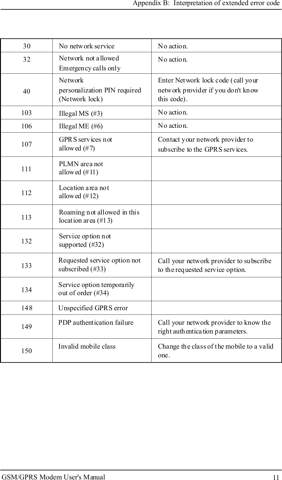
ETEK TECHNOLOGY TD-8013 GSM/GPRS MODEM User Manual
ETEK TECHNOLOGY(SHENZHEN) CO., LTD. GSM/GPRS MODEM
UserManual.wiki
>
ETEK TECHNOLOGY
>
TD 8013 User Manual
User Manual
Navigation menu
Upload a User Manual
Namespaces
Wiki Guide
HTML
PDF
Info
Views
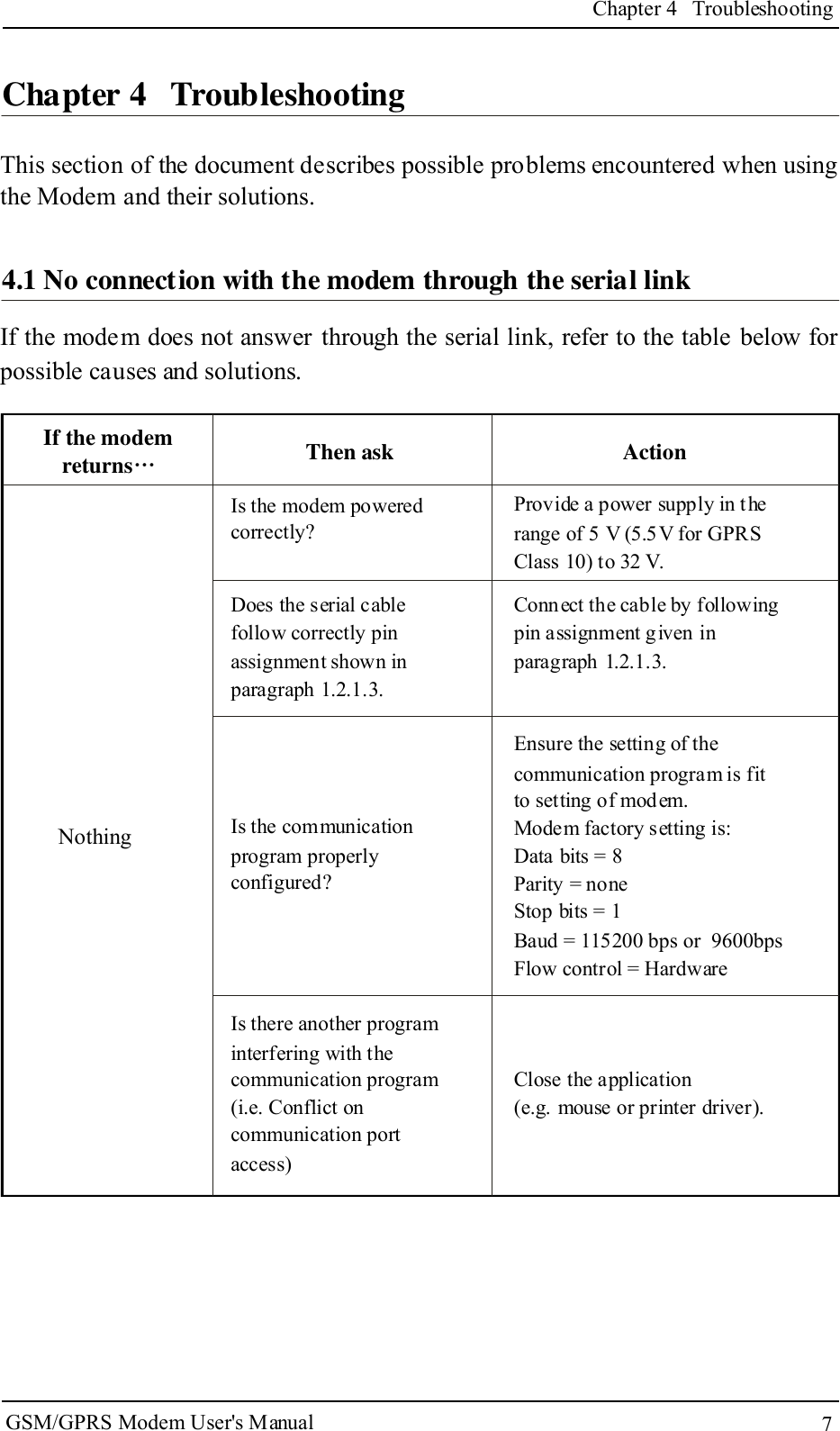
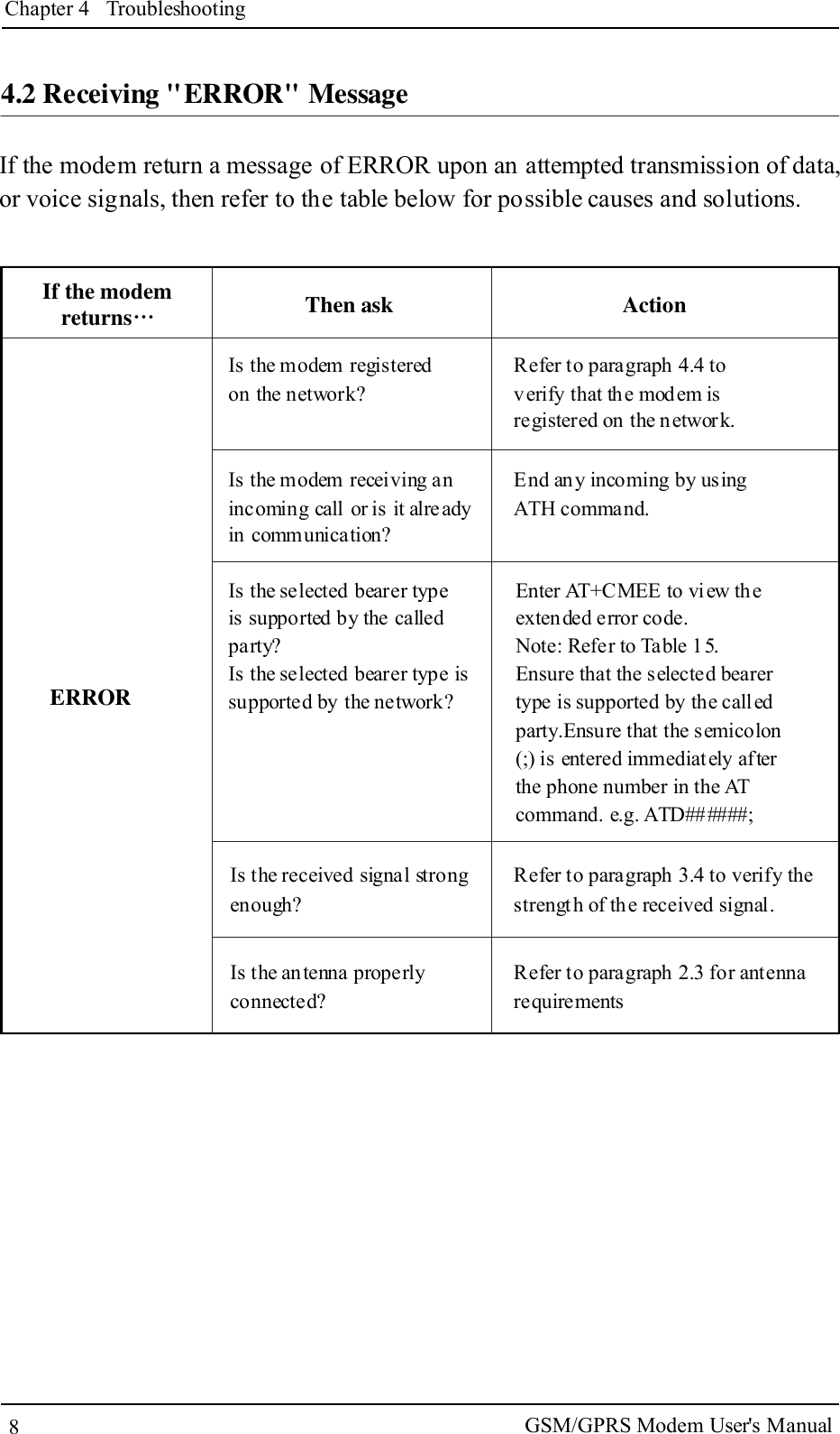
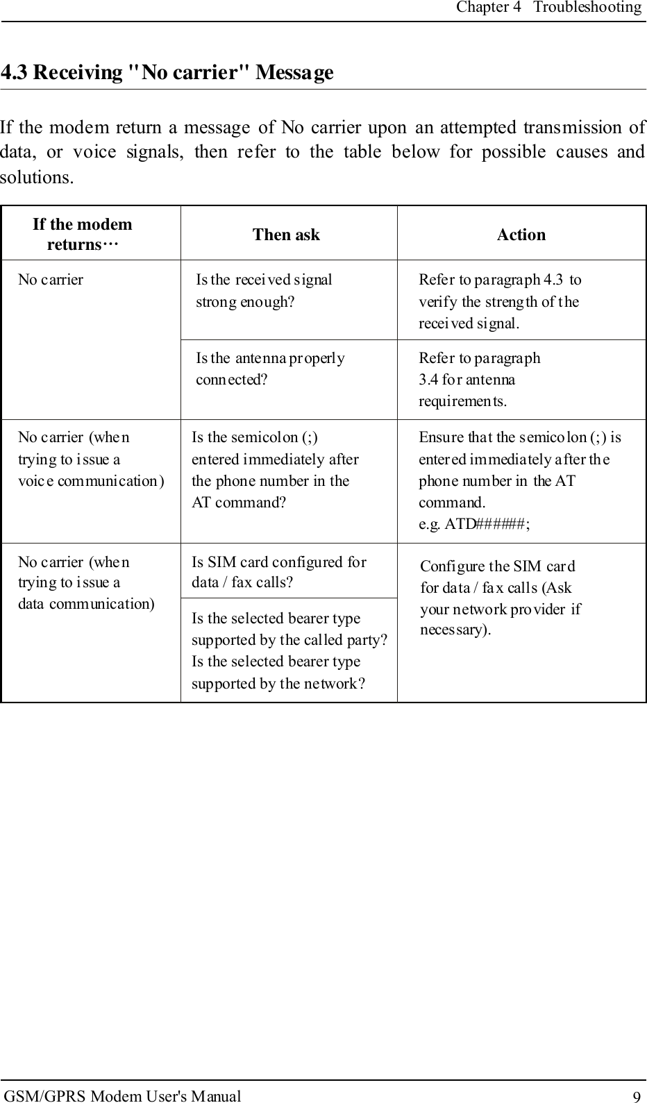
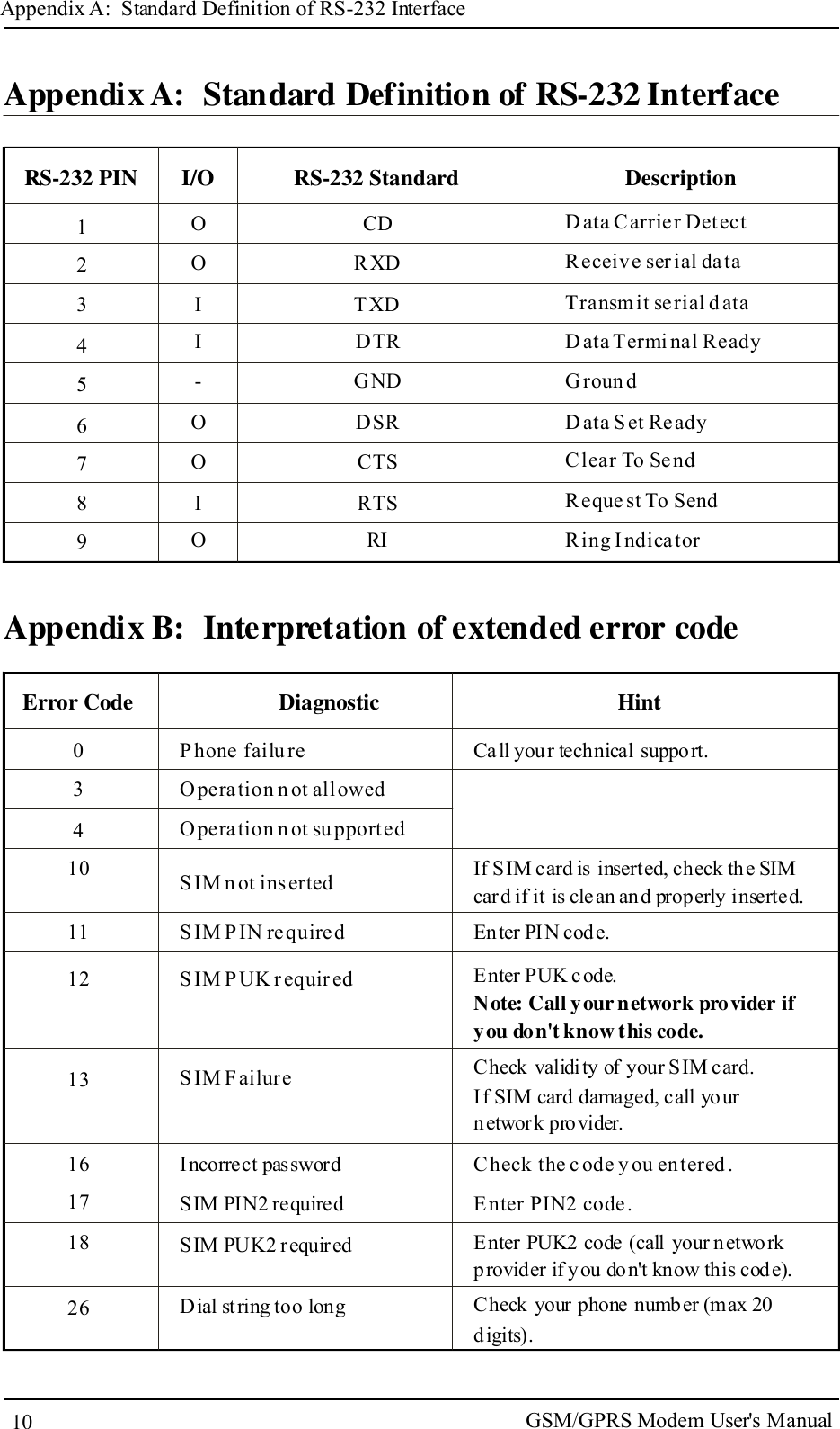
User Manual
Discussion / Help
Navigation