ETi Solid State Lighting 9050102016 Motion Sensor User Manual Manual
Elec-Tech International Co., Ltd. Motion Sensor Manual
User Manual
Item/unit Parameter
Operating voltage 120V /60Hz
Switched power 200W (capacitive)
Standby power <0.5w
Warmming-up time 20s
Detection area 10%/50%/75%/100%, can be customized
Hold time 5S/90S/5min/15min, can be customized
Daylight threshold 2~50lux disable
Microwave frequency 5.8GHz+/-75MHz
Microwave power <1mw
Detection range Max. (oxH): 10m x 6m
Detection angle 30°~150°
Mounting height Max.6m
Operating temperature -20°C~70°C
IP rating IP20
Certificate ETL FCC
IntheendwewillonlyneedEnglishandSpanishfortheUS. WewilldoaseparateSpanish
IM. TheIMforthemotionwrapisincluded. Refertothatsowearetellingthesamestory
withregardtopersonallyadjustingthesensor. Thisisnotaneasyconceptformanypeople
tograspsoyouhavetokeepaskingyourselfasyouwritethese“canIunderstanditsimply”?
Debcanyouputyourmarketingexpertiseonthisafterthenextdraft?
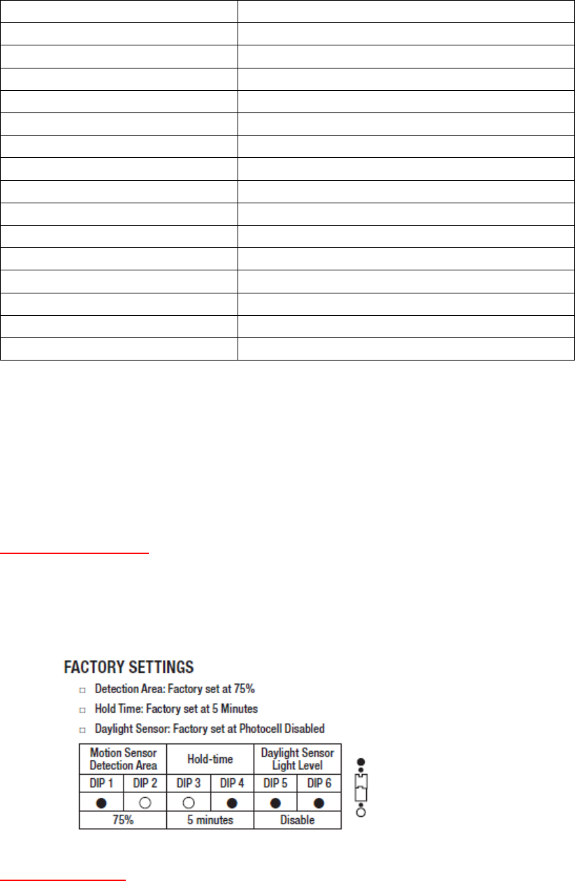
MotionSensorSettings
Youcanadjustthesettingsfordetectionarea,holdtimeanddaylightsensitivity
shouldyouwishto. Thesensorcomesfactorypre‐setatthemostpopularsettings. To
adjustyou’llneedtosimplymovethedipswitchesaccordingtothesettingyou
desire. Pleaserefertothetablebelow.
InstallationOptions
Thissensorisdesignedtoworkwithbothselectlinkablepluginfixturesandalsowithboth
LEDandFluorescentfixturesthatutilizeadirectwireconnectionmethod.
1. MountinginlinetoalinkableLEDfixture
a. Turnpoweroff
5.79GHz
b. Thesensorwillmountbetweenyourpowercordendandthefixture.(the
drawinggoeshere)
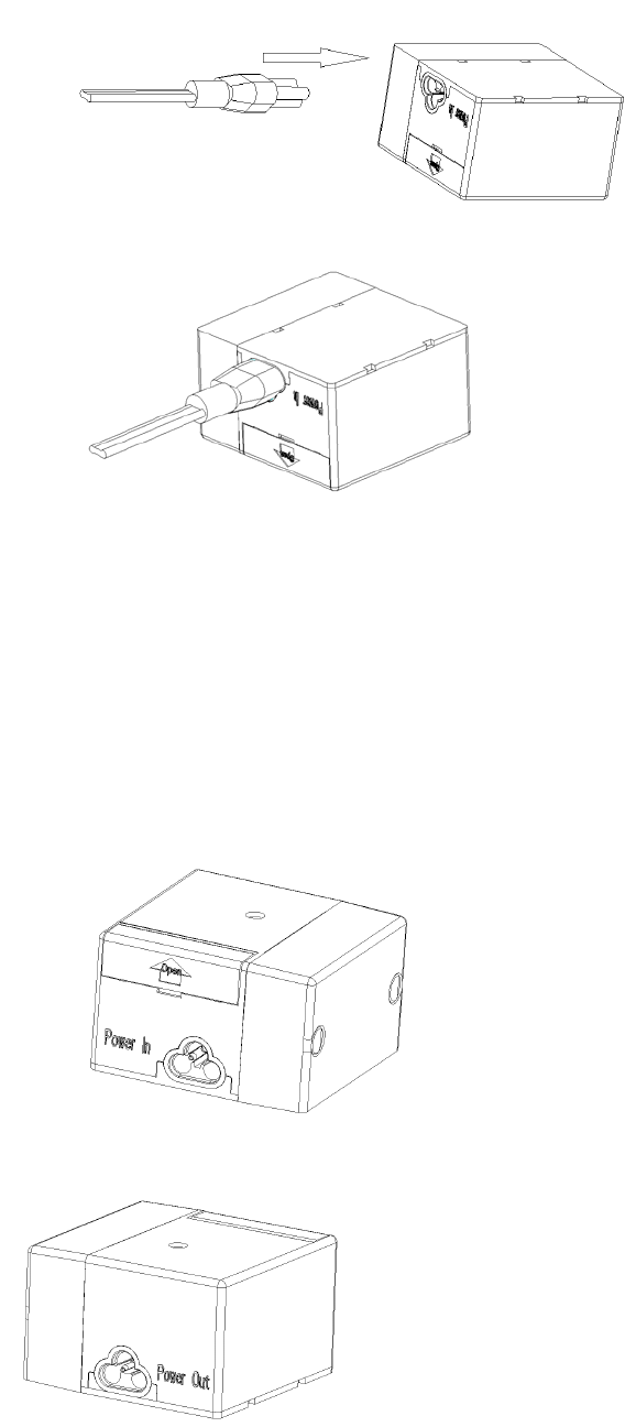
c. ThesensornoteswhichendispowerInandwhichispowerOut(show
drawingofbothhere)
Powerin:
Powerout:
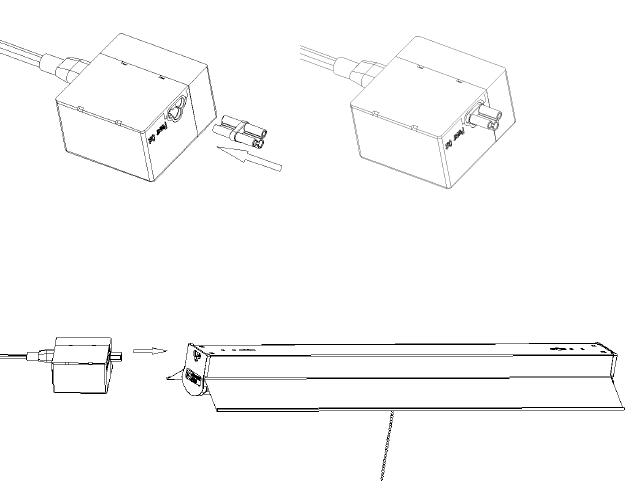
d. Usethesmallmaletomaleconnectorprovidedtomaketheconnectionon
thepoweroutendofthesensorbyinsertingit. Oncetheconnectorisin
thesensorsimplypushitintothepowerendofthefixture(showdrawing
here)
e. Nextsimplyinsertthepowercordtothepowerinendofthe
sensor. Makesurebothconnectionsfitsecurely
f. Turnthepoweron. Makesurethepullchainisintheonposition
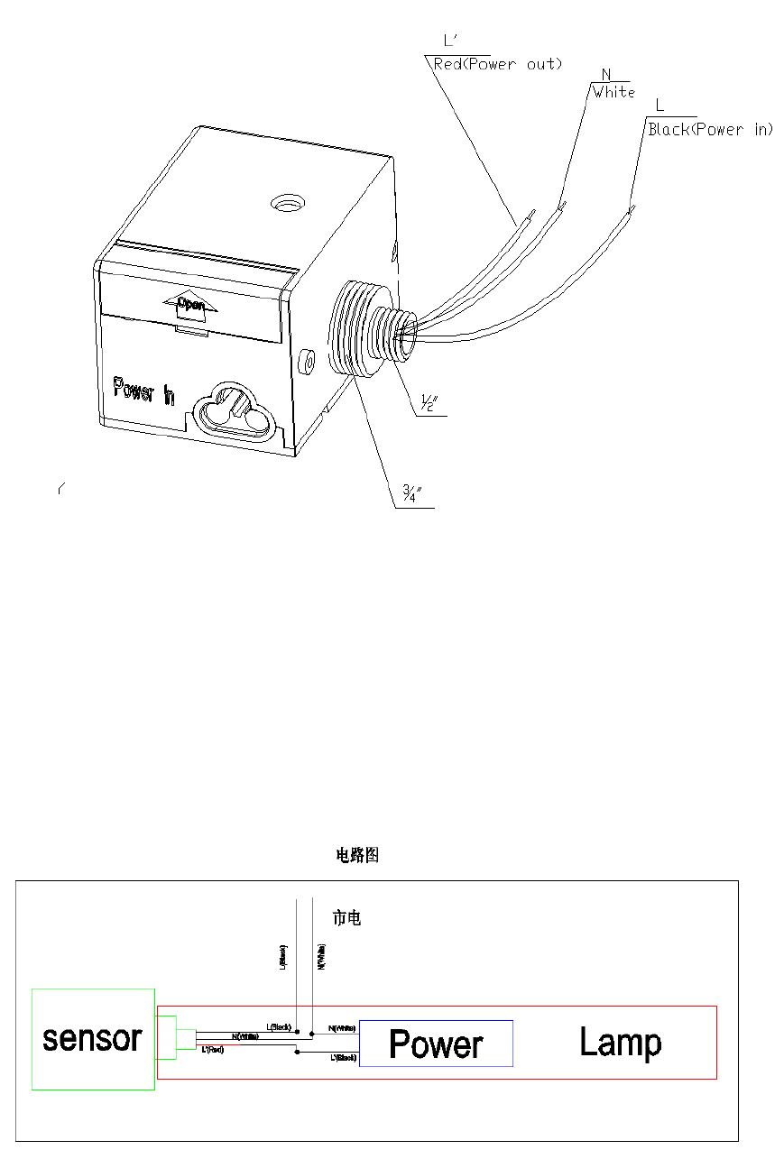
2. MountingviaDirectWiringmethod
a. Turnpoweroff
b. Determinewhichsizeknockoutisrequired. Oursensorcomeswith2
convenientsizes(3/4”and½”)(doublecheckwithHoushengmin)
c. Useonlythelocknutforthatsize
d. Preparethefixturebyremovingthelensifneededandthenremovethe
knockoutwhereyouwishtomountthesensor.
e. Followthewiringdiagrambelow(addwiringdiagram)

bymakingtheconnectionwiththewirenutsprovided. Importanttonotethere thatthe
locknutshouldbeontheinsideofthefixturewallwiththewirescomingthroughthemiddle
(insertdrawinghere)(nowirenutsinmysampleyousent,pleaseaddtocoverallwires)
f. Oncetheconnectionsaremadeinsertthethreadedendintothehole
completelyandtightenthelocknutdownbyhand. Forafirmfitgentlyuse
plierstosnugthelocknutdown
g. Replacethelensifneeded.
h. Turnpoweron
TroubleShootingSectionNeeded
• Addtipshere
FCCComplianceStatement:ThisdevicecomplieswithPart15oftheFCCrules.Operationis
subjectedtothefollowingtwoconditions:(1)thisdevicemaynotcauseharmful
interference,and(2)thisdevicemustacceptanyinterferencereceived,including
interferencethatmaycauseundesiredoperation.
ICComplianceStatement:ThisdevicecomplieswithIndustryCanada’slicence‐exempt
RSSs.Operationissubjecttothefollowingtwoconditions:(1)thisdevicemaynotcause
interference,and(2)thisdevicemustacceptanyinterference,includinginterferencethat
maycauseundesiredoperationofthedevice.
CetappareilestconformeauxCNRexemptesdelicenced'IndustrieCanada.Son
fonctionnementestsoumisauxdeuxconditionssuivantes:
(1)Cedispositifnepeutcauserd'interférences;et
(2)Cedispositifdoitacceptertouteinterférence,ycomprislesinterférencesquipeuvent
causerunmauvaisfonctionnementdel'appareil.
Changesormodificationsnotexpresslyapprovedbythepartyresponsibleforcompliance
couldvoidyourauthoritytooperatetheequipment.