EUCHNER KG 01 Safety Switch with RFID User Manual Manual
EUCHNER GmbH Co.KG Safety Switch with RFID Manual
UserManual.wiki
>
EUCHNER KG
>
01 User Manual
>
Manual
Contents
1.
Manual
2.
Safety Information
Manual
Navigation menu
Upload a User Manual
Namespaces
Wiki Guide
HTML
PDF
Info
Views
User Manual
Discussion / Help
Navigation
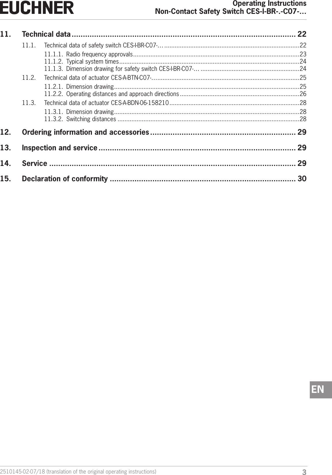
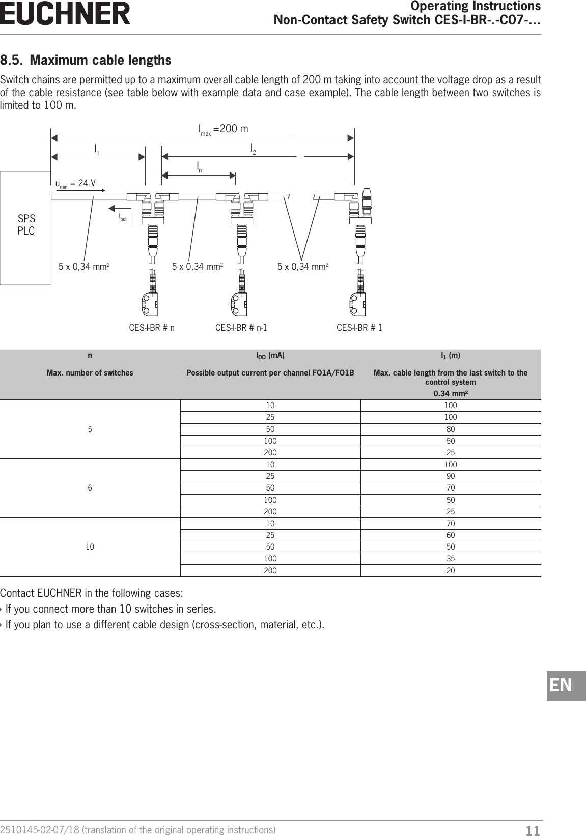
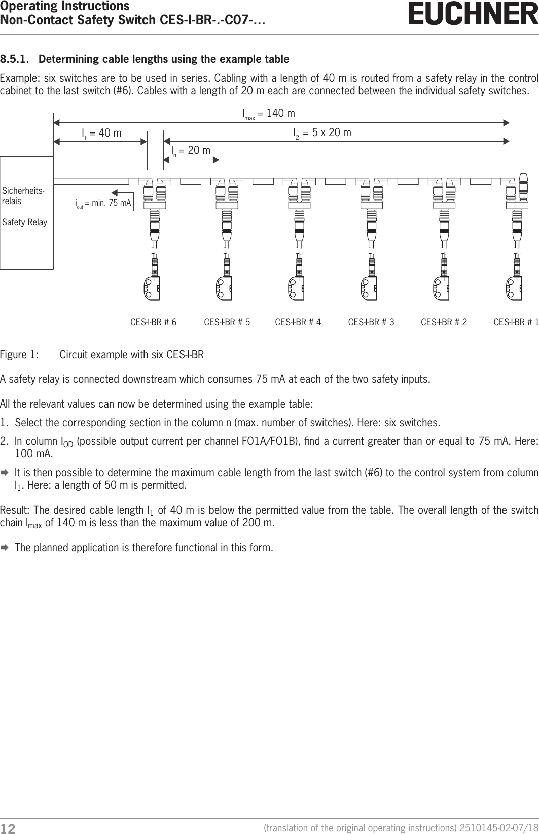
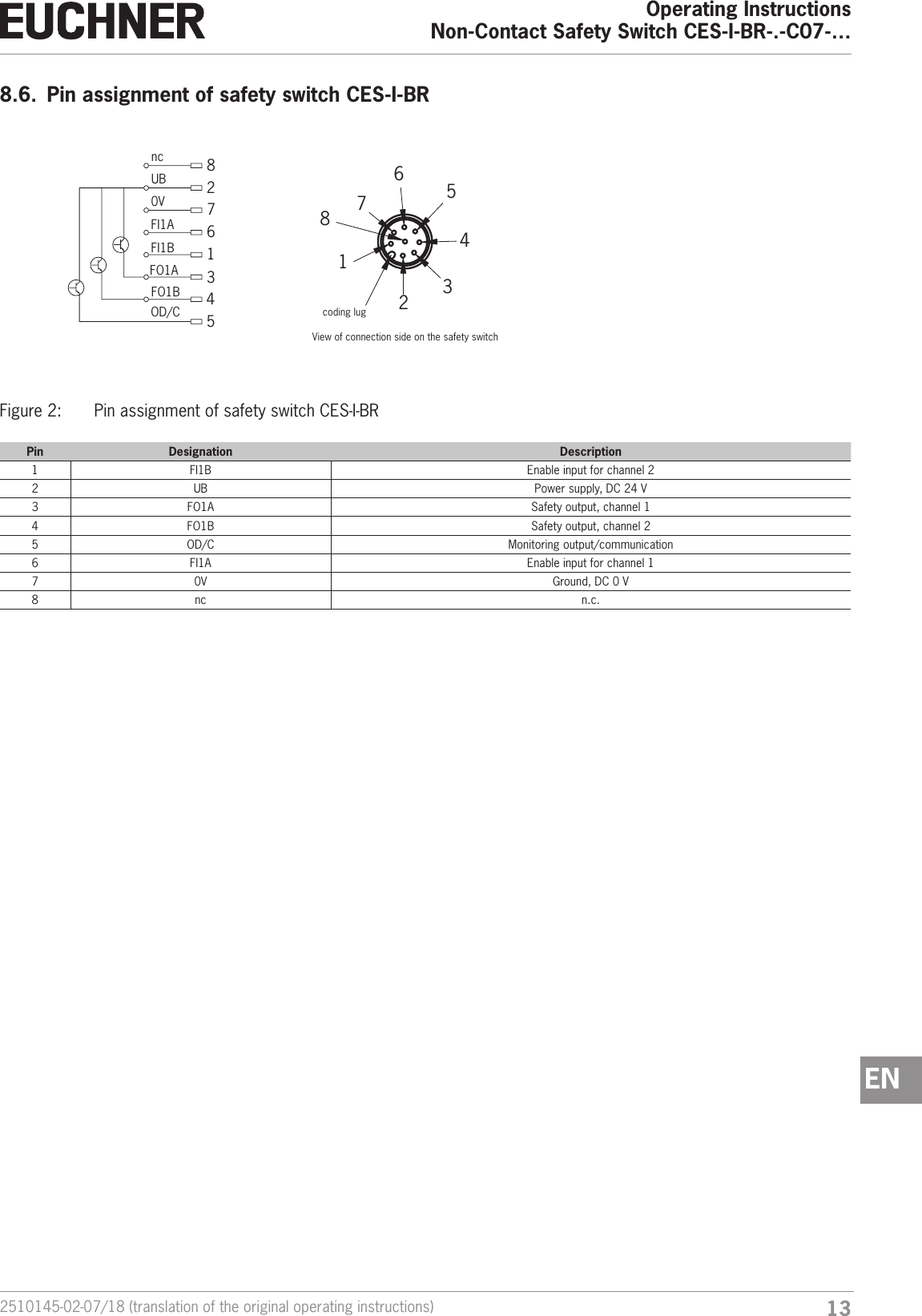
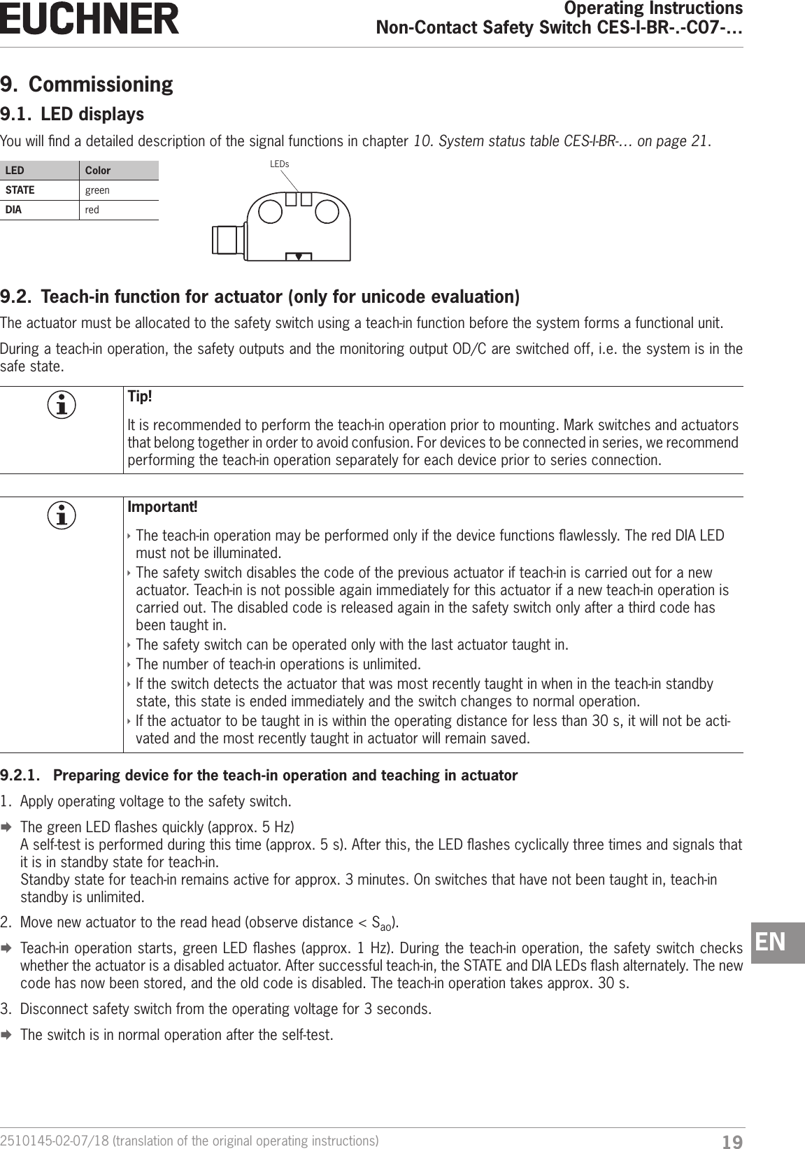
![Operating InstructionsNon-Contact Safety Switch CES-I-BR-.-C07-…14 (translation of the original operating instructions) 2510145-02-07/188.7. Pin assignment of Y-distributorM12x1max. 45Ø 14,5Strapping plug 097645 4-pin, plug(gure similar)Y-distributor with connecting cable 111696 or 112395Socketpin SocketPin FunctionX2.1 UBX2.2 FO1AX2.3 0VX2.4 FO1BX2.5 RSTPin FunctionX3.1 UBX3.2 FI1AX3.3 0VX3.4 FI1BX3.5 RST121209762745°15,14856312735,120,51245334215Mx1Ø 14,6Mx1( )Y-distributor 097627SocketPin assignment of safety switch CES-I-BR (8-pin plug) and Y-distributor (8-pin socket)Pin FunctionX1.1 FI1BX1.2 UBX1.3 FO1AX1.4 FO1BX1.5 ODX1.6 FI1AX1.7 0VX1.8 RSTpin SocketM12x144454115M12x115 15M12x133A B485631271245334215Length lOrder no. Lengthl [mm]111696 200112395 1000Pin FunctionX2.1 UBX2.2 FO1AX2.3 0VX2.4 FO1BX2.5 RSTPin FunctionX3.1 UBX3.2 FI1AX3.3 0VX3.4 FI1BX3.5 RST](https://usermanual.wiki/EUCHNER-KG/01.Manual/User-Guide-3912737-Page-14.png)