EUCHNER KG 01 Safety Switch with RFID User Manual Manual
EUCHNER GmbH Co.KG Safety Switch with RFID Manual
Contents
- 1. Manual
- 2. Safety Information
Manual

EN
Operating Instructions
Non-Contact Safety Switch
CES-I-BR-.-C07-… (Unicode/Multicode)

Operating Instructions
Non-Contact Safety Switch CES-I-BR-.-C07-…
2(translation of the original operating instructions) 2510145-02-07/18
Contents
1. About this document ............................................................................................. 4
1.1. Scope ............................................................................................................................................ 4
1.2. Target group ..................................................................................................................................4
1.3. Key to symbols ...............................................................................................................................4
1.4. Supplementary documents ..............................................................................................................4
2. Correct use .......................................................................................................... 5
3. Description of the safety function .......................................................................... 6
4. Exclusion of liability and warranty ......................................................................... 6
5. General safety precautions ................................................................................... 6
6. Function ............................................................................................................... 7
6.1. Door monitoring output ...................................................................................................................7
6.2. Limit-range monitoring ....................................................................................................................7
6.3. Switching states .............................................................................................................................7
7. Installation ........................................................................................................... 8
8. Electrical connection ............................................................................................ 9
8.1. Notes about .........................................................................................................................10
8.2. Safety in case of faults .................................................................................................................. 10
8.3. Fuse protection for power supply ...................................................................................................10
8.4. Requirements for connection cables ...............................................................................................10
8.5. Maximum cable lengths .................................................................................................................11
8.5.1. Determining cable lengths using the example table .............................................................12
8.6. Pin assignment of safety switch CES-I-BR ........................................................................................ 13
8.7. Pin assignment of Y-distributor ....................................................................................................... 14
8.8. Connection of a single BR device ...................................................................................................15
8.9. Connection of several devices in a switch chain ..............................................................................16
8.10. Notes on operation with safe control systems .................................................................................18
9. Commissioning ................................................................................................... 19
9.1. LED displays ................................................................................................................................19
9.2. Teach-in function for actuator (only for unicode evaluation) ...............................................................19
9.2.1. Preparing device for the teach-in operation and teaching in actuator ....................................19
9.3. Functional check ........................................................................................................................... 20
9.3.1. Electrical function test ......................................................................................................20
10. System status table CES-I-BR-… .......................................................................... 21

3
2510145-02-07/18 (translation of the original operating instructions)
Operating Instructions
Non-Contact Safety Switch CES-I-BR-.-C07-…
EN
11. Technical data .................................................................................................... 22
11.1. Technical data of safety switch CES-I-BR-C07-… ..............................................................................22
11.1.1. Radio frequency approvals ................................................................................................ 23
11.1.2. Typical system times ........................................................................................................24
11.1.3. Dimension drawing for safety switch CES-I-BR-C07-… .........................................................24
11.2. Technical data of actuator CES-A-BTN-C07-… ..................................................................................25
11.2.1. Dimension drawing ........................................................................................................... 25
11.2.2. Operating distances and approach directions .....................................................................26
11.3. Technical data of actuator CES-A-BDN-06-158210 ...........................................................................28
11.3.1. Dimension drawing ........................................................................................................... 28
11.3.2. Switching distances .........................................................................................................28
12. Ordering information and accessories ................................................................. 29
13. Inspection and service ........................................................................................ 29
14. Service .............................................................................................................. 29
15. Declaration of conformity ................................................................................... 30
Operating Instructions
Non-Contact Safety Switch CES-I-BR-.-C07-…
4(translation of the original operating instructions) 2510145-02-07/18
1. About this document
1.1. Scope
These operating instructions are valid for all CES-I-BR-.-C07-… These operating instructions, the document “Safety information
and maintenance” and any enclosed data sheet form the complete user information for your device.
1.2. Target group
Design engineers and installation planners for safety devices on machines, as well as setup and servicing staff possessing
special expertise in handling safety components.
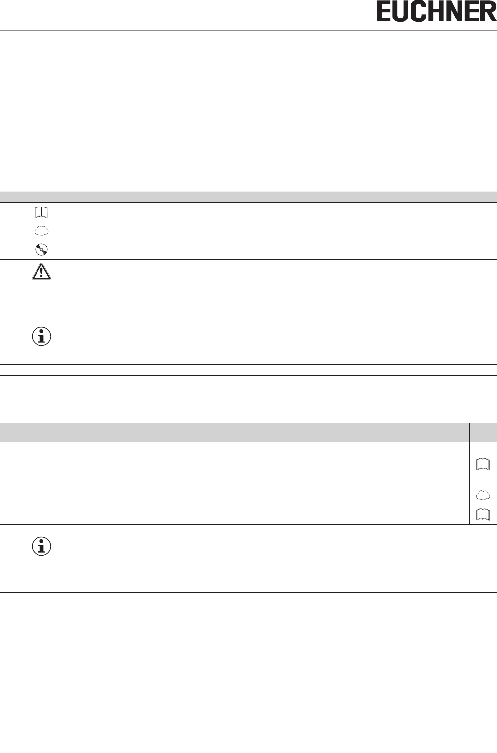
1.3. Key to symbols
Symbol/depiction Meaning
Printed document
www Document is available for download at www.euchner.com
Document on CD
DANGER
WARNING
CAUTION
Safety precautions
Danger of death or severe injuries
Warning about possible injuries
Caution slight injuries possible
NOTICE
Important!
Notice about possible device damage
Important information
Tip Useful information
1.4. Supplementary documents
The overall documentation for this device consists of the following documents:
Document title
(document number) Contents
Safety Information and
Maintenance
Safety Switch
CES-AP/CES-AR/CES-BR
(2514431)
Basic information for safe setup and service
Operating Instructions
(2510145) (this document) www
Possibly enclosed data
sheet Item-specic information about deviations or additions
Important!
Always read all documents to gain a complete overview of safe installation, setup and use of the device.
The documents can be downloaded from www.euchner.com. For this purpose enter the doc. no. or
the order number for the device in the search box.
5
2510145-02-07/18 (translation of the original operating instructions)
Operating Instructions
Non-Contact Safety Switch CES-I-BR-.-C07-…
EN
2. Correct use
Safety switches series CES-I-BR are interlocking devices without guard locking (type4). The device meets the requirements
according to ENIEC60947-5-3. Devices with unicode evaluation possess a high coding level, devices with multicode eval-
uation possess a low coding level.
In combination with a movable guard and the machine control, this safety component prevents dangerous machine functions
from occurring while the guard is open. A stop command is triggered if the guard is opened during the dangerous machine
function.
This means:
ÌStarting commands that cause a dangerous machine function must become active only when the guard is closed.
ÌOpening the guard triggers a stop command.
ÌClosing a guard must not cause automatic starting of a dangerous machine function. A separate start command must
be issued. For exceptions, refer to ENISO12100 or relevant C-standards.
Before the device is used, a risk assessment must be performed on the machine, e.g. in accordance with the following
standards:
ÌENISO13849-1, Safety of machinery – Safety-related parts of control systems – Part 1: General principles for design
ÌENISO12100, Safety of machinery – General principles for design – Risk assessment and risk reduction
ÌIEC62061, Safety of machinery – Functional safety of safety-related electrical, electronic and programmable electronic
control systems.
Correct use includes observing the relevant requirements for installation and operation, particularly based on the following
standards:
ÌENISO13849-1, Safety of machinery – Safety-related parts of control systems – Part 1: General principles for design
ÌENISO14119, Safety of machinery – Interlocking devices associated with guards – Principles for design and selection
ÌEN60204-1, Safety of machinery – Electrical equipment of machines.
The safety switch is only allowed to be operated in conjunction with the intended EUCHNER CES actuators and the related
connection components from EUCHNER. On the use of different actuators or other connection components, EUCHNER
provides no warranty for safe function.
Connection of several devices in a BR switch chain is permitted only using devices intended for series connection in a BR
switch chain. Check this in the instructions of the device in question.
A maximum of 20 safety switches are allowed to be operated in a switch chain.
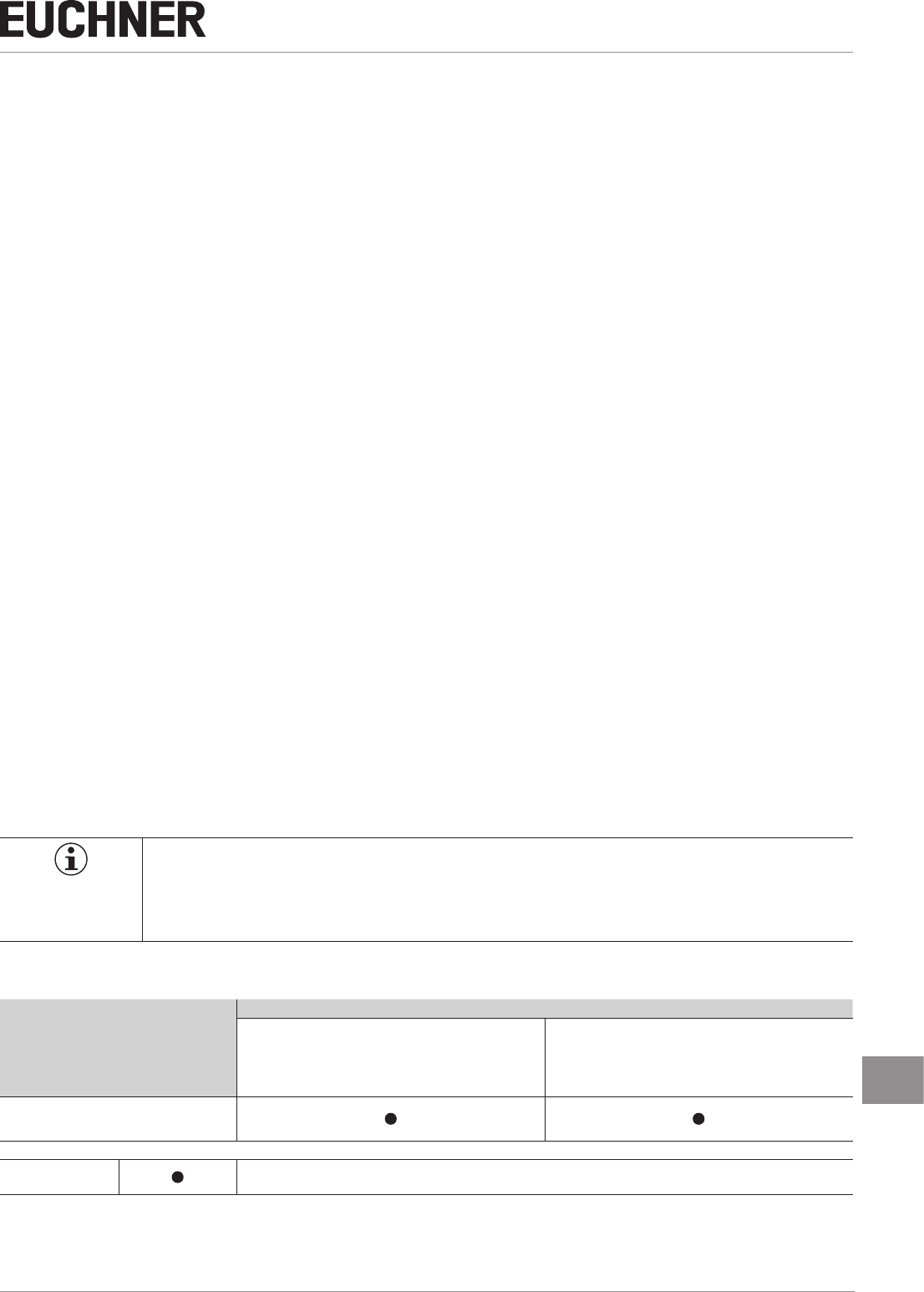
Important!
ÌThe user is responsible for the proper integration of the device into a safe overall system. For this
purpose, the overall system must be validated, e.g. in accordance with ENISO13849-2.
ÌIt is only allowed to use components that are permissible in accordance with the table below.
Table 1: Possible combinations for CES components
Safety Switch
Actuator
CES-A-BTN-C07-… CES-A-BDN-C06-…
CES-I-BR-.-C07-...
Key to symbols Combination possible
Operating Instructions
Non-Contact Safety Switch CES-I-BR-.-C07-…
6(translation of the original operating instructions) 2510145-02-07/18
3. Description of the safety function
Devices from this series feature the following safety functions:
Monitoring of the guard position
(interlocking device according to ENISO14119)
ÌSafety function:
- The safety outputs are switched off when the guard is open (see chapter 6.3. Switching states on page 7).
ÌSafety characteristics: category, Performance Level, PFHD (see chapter 11. Technical data on page 22).
4. Exclusion of liability and warranty
In case of failure to comply with the conditions for correct use stated above, or if the safety instructions are not followed,
or if any servicing is not performed as required, liability will be excluded and the warranty void.
5. General safety precautions
Safety switches fulll personnel protection functions. Incorrect installation or tampering can lead to fatal injuries to personnel.
Check the safe function of the guard particularly
Ìafter any setup work
Ìafter the replacement of a system component
Ìafter an extended period without use
Ìafter every fault
Independent of these checks, the safe function of the guard should be checked at suitable intervals as part of the mainte-
nance schedule.
WARNING
Danger to life due to improper installation or due to bypassing (tampering). Safety components fulll
a personnel protection function.
ÌSafety components must not be bypassed, turned away, removed or otherwise rendered ineffec-
tive. On this topic pay attention in particular to the measures for reducing the possibility of bypass-
ing according to ENISO14119:2013, section 7.
ÌThe switching operation must be triggered only by actuators designated for this purpose.
ÌPrevent bypassing by means of replacement actuators (only for multicode evaluation). For this
purpose, restrict access to actuators and to keys for releases, for example.
ÌMounting, electrical connection and setup only by authorized personnel possessing the following
knowledge:
- specialist knowledge in handling safety components
- knowledge about the applicable EMC regulations
- knowledge about the applicable regulations on occupational safety and accident prevention.
Important!
Prior to use, read the operating instructions and keep these in a safe place. Ensure the operating
instructions are always available during mounting, setup and servicing. For this reason you should
archive a printed copy of the operating instructions. You can download the operating instructions from
www.euchner.com.
7
2510145-02-07/18 (translation of the original operating instructions)
Operating Instructions
Non-Contact Safety Switch CES-I-BR-.-C07-…
EN
6. Function
The safety switch monitors the position of movable guards. The safety outputs are switched on/off when the actuator is
moved into/out of the operating distance.
The system consists of the following components: coded actuator (transponder) and switch.
Whether the device learns the complete actuator code (unicode) or not (multicode) depends on the respective version.
ÌDevices with unicode evaluation: The actuator must be assigned to the safety switch by a teach-in operation so that
it is detected by the system. This unambiguous assignment ensures a particularly high level of protection against tam-
pering. The system thus possesses a high coding level.
ÌDevices with multicode evaluation: Unlike systems with unique code detection, on multicode devices a specic code
is not requested but instead it is only checked whether the actuator is of a type that can be detected by the system
(multicode detection). There is no exact comparison of the actuator code with the taught-in code in the safety switch
(unique code detection). The system possesses a low coding level.
When the guard is closed, the actuator is moved towards the safety switch. When the switch-on distance is reached, power
is supplied to the actuator by the switch and data are transferred.
If a permissible code is detected, the safety outputs are switched on.
The safety outputs are switched off when the guard is opened.
In the event of a fault in the safety switch, the safety outputs are switched off and the DIA LED illuminates red. The occurrence
of faults is detected at the latest on the next demand to close the safety outputs (e.g. on starting).
6.1. Door monitoring output
The door monitoring output is switched on as soon as a valid actuator is detected in the operating distance.
6.2. Limit-range monitoring
If the safety door with the actuator should settle over time, the actuator can drift out of the read head operating distance.
The device recognizes this situation and indicates that the actuator is in the limit range by ashing the STATE LED. This
allows the safety door to be readjusted in time. Also see chapter 10. System status table CES‑I‑BR‑… on page 21.
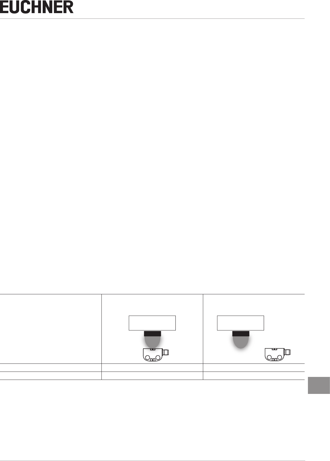
6.3. Switching states
The detailed switching states for your switch can be found in the system status table. All safety outputs, monitoring outputs
and display LEDs are described there.
Guard closed
(actuator in operating distance and permissible
code detected)
Guard open
(actuator not in the operating distance)
Safety outputs FO1A and FO1B on off
Monitoring output OD/C on off
Operating Instructions
Non-Contact Safety Switch CES-I-BR-.-C07-…
8(translation of the original operating instructions) 2510145-02-07/18
7. Installation
CAUTION
Safety switches must not be bypassed (bridging of contacts), turned away, removed or otherwise
rendered ineffective.
ÌObserve ENISO14119:2013, section 7, for information about reducing the possibilities for by-
passing an interlocking device.
NOTICE
Risk of damage to equipment and malfunctions as a result of incorrect installation.
ÌSafety switches and actuators must not be used as an end stop.
ÌObserve ENISO14119:2013, sections 5.2 and 5.3, for information about fastening the safety
switch and the actuator.
ÌFrom the assured switch-off distance Sar, the safety outputs are safely shut down.
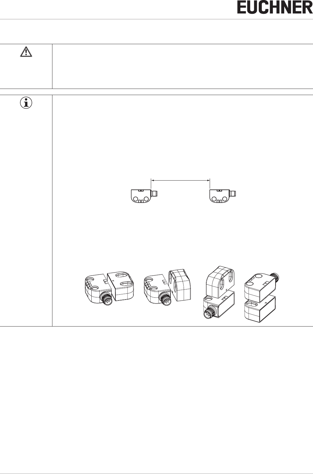
ÌWhen mounting several safety switches, observe the stipulated minimum distance to avoid mutual
interference.
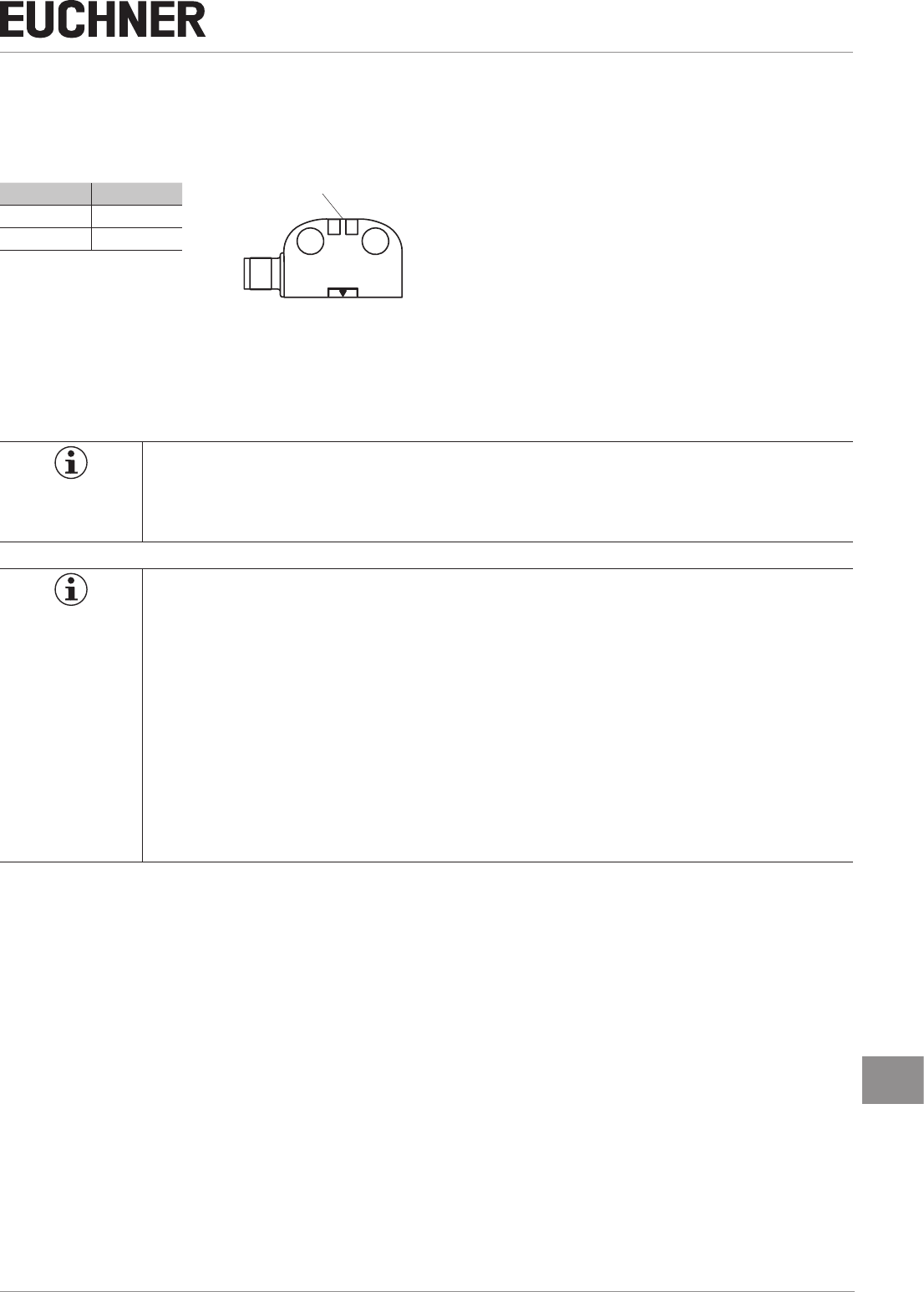
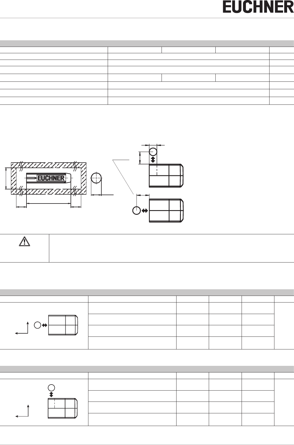
.
min. 140 mm
ÌThe operating distance changes during the mounting of the actuator as a function of the material
used for the guard.
ÌObserve direction of arrow on the device (see gure below).
Permissible approach directions
BA
CD
z
x
y
x
z
y
BA
CD
z
x
y
x
z
y
Note the following points:
ÌActuator and safety switch must be easily accessible for inspection and replacement.
ÌActuator and safety switch must be tted so that
- a minimum distance is maintained with a side approach direction to avoid entering the area of possible side lobes. See
chapter 11. Technical data, section Typical operating distance for the related actuator.
- when the guard is open up to the distance Sar (assured switch-off distance), a hazard is excluded.
- the actuator is positively mounted on the guard, e.g. by using the safety screws included.
- they cannot be removed or tampered with using simple means.
ÌPay attention to the maximum tightening torque for the read head or safety switch and actuator mountings of 0.8Nm.
ÌSeal the mounting holes after mounting using the caps provided to prevent the accumulation of dirt.
ÌIn order to avoid damage, the connection cable must be laid with protection in areas in which high-pressure cleaners are
used.
9
2510145-02-07/18 (translation of the original operating instructions)
Operating Instructions
Non-Contact Safety Switch CES-I-BR-.-C07-…
EN
8. Electrical connection
The following connection options are available:
ÌSeparate operation
ÌSeries connection with Y-distributors
ÌSeries connection, e.g. with wiring in the control cabinet.
WARNING
If there is a mistake, loss of the safety function due to incorrect connection.
ÌTo ensure safety, both safety outputs must always be evaluated.
ÌMonitoring outputs must not be used as safety outputs.
ÌLay the connection cables with protection to prevent the risk of short circuits.
CAUTION
Risk of damage to equipment or malfunctions as a result of incorrect connection.
ÌDo not use a control system with pulsing or switch off the pulsing function in your control system.
The device generates its own test pulses on the safety outputs. A downstream control system
must tolerate these test pulses, which may have a length of up to 300µs.
The test pulses are only output with the safety outputs switched off during device start.
Depending on the inertia of the downstream device (control system, relay, etc.), this can lead to
short switching processes.
ÌThe inputs on an evaluation unit connected must be positive-switching, as the two outputs on the
safety switch deliver a level of +24V in the switched-on state.
ÌAll the electrical connections must either be isolated from the mains supply by a safety transformer
according to IEC 61558-2-6 with limited output voltage in the event of a fault, or by other equivalent
isolation measures (PELV).
ÌAll electrical outputs must have an adequate protective circuit for inductive loads. The outputs
must be protected with a free-wheeling diode for this purpose. RC interference suppression units
must not be used.
ÌPower devices which are a powerful source of interference must be installed in a separate location
away from the input and output circuits for signal processing. The cable routing for safety circuits
should be as far away as possible from the cables of the power circuits.
ÌTo avoid EMC interference, the physical environmental and operating conditions at the in-
stallation site of the device must comply with the requirements according to the standard
EN60204-1:2006, section 4.4.2 (EMC).
ÌPlease pay attention to any interference elds from devices such as frequency converters or
induction heating systems. Observe the EMC instructions in the manuals from the respective man-
ufacturer.
Important!
If the device does not appear to function when operating voltage is applied (e.g. green STATE LED
does not ash), the safety switch must be returned unopened to the manufacturer.
Operating Instructions
Non-Contact Safety Switch CES-I-BR-.-C07-…
10 (translation of the original operating instructions) 2510145-02-07/18
8.1. Notes about
Important!
ÌFor use and operation as per the requirements 1), a power supply with the feature “for use in
class 2 circuits” must be used.
Alternative solutions must comply with the following requirements:
- Electrically isolated power supply unit with a max. open-circuit voltage of 30VDC and a limited
current of max. 8A.
ÌFor use and applications as per the requirements of 1), a connection cable listed under the UL
category code CYJV2 or CYJV must be used.
1) Note on the scope of the UL approval: the devices have been tested as per the requirements of UL508 and CSA/ C22.2 no. 14 (protection against electric shock
and re). Only for applications as per NFPA79 (Industrial Machinery).
8.2. Safety in case of faults
ÌThe operating voltage UB is reverse polarity protected.
ÌThe safety outputs are short circuit-proof.
ÌA short circuit between the safety outputs is detected by the switch.
ÌA short circuit in the cable can be excluded by laying the cable with protection.
8.3. Fuse protection for power supply
The power supply must be provided with fuse protection depending on the number of switches and current required for the
outputs. The following rules apply:
Max. current consumption of an individual switch Imax
Imax = IUB + IOD + IFO1A+FO1B
IUB = Switch operating current (40mA)
IOD = Load current of monitoring outputs (max. 50mA)
IFO1A+FO1B = Load current of safety outputs FO1A + FO1B (2xmax. 150mA)
Max. current consumption of a switch chain Σ Imax
Σ Imax = IFO1A+FO1B + nx(IUB + IOD)
n = Number of connected switches
8.4. Requirements for connection cables
CAUTION
Risk of damage to equipment or malfunctions as a result of incorrect connection cables.
ÌUse connection components and connection cables from EUCHNER.
ÌOn the usage of other connection components, the requirements in the following table apply.
EUCHNER provides no warranty for safe function in case of failure to comply with these require-
ments.
Observe the following requirements with respect to the connection cables:
Parameter Value Unit
Conductor cross-section, min. 0.25 … 0.34 mm²
R max. 80 W/km
C max. 120 nF/km
L max. 0.65 mH/km
Recommended cable type LIYY 8 x 0.34mm²
11
2510145-02-07/18 (translation of the original operating instructions)
Operating Instructions
Non-Contact Safety Switch CES-I-BR-.-C07-…
EN
8.5. Maximum cable lengths
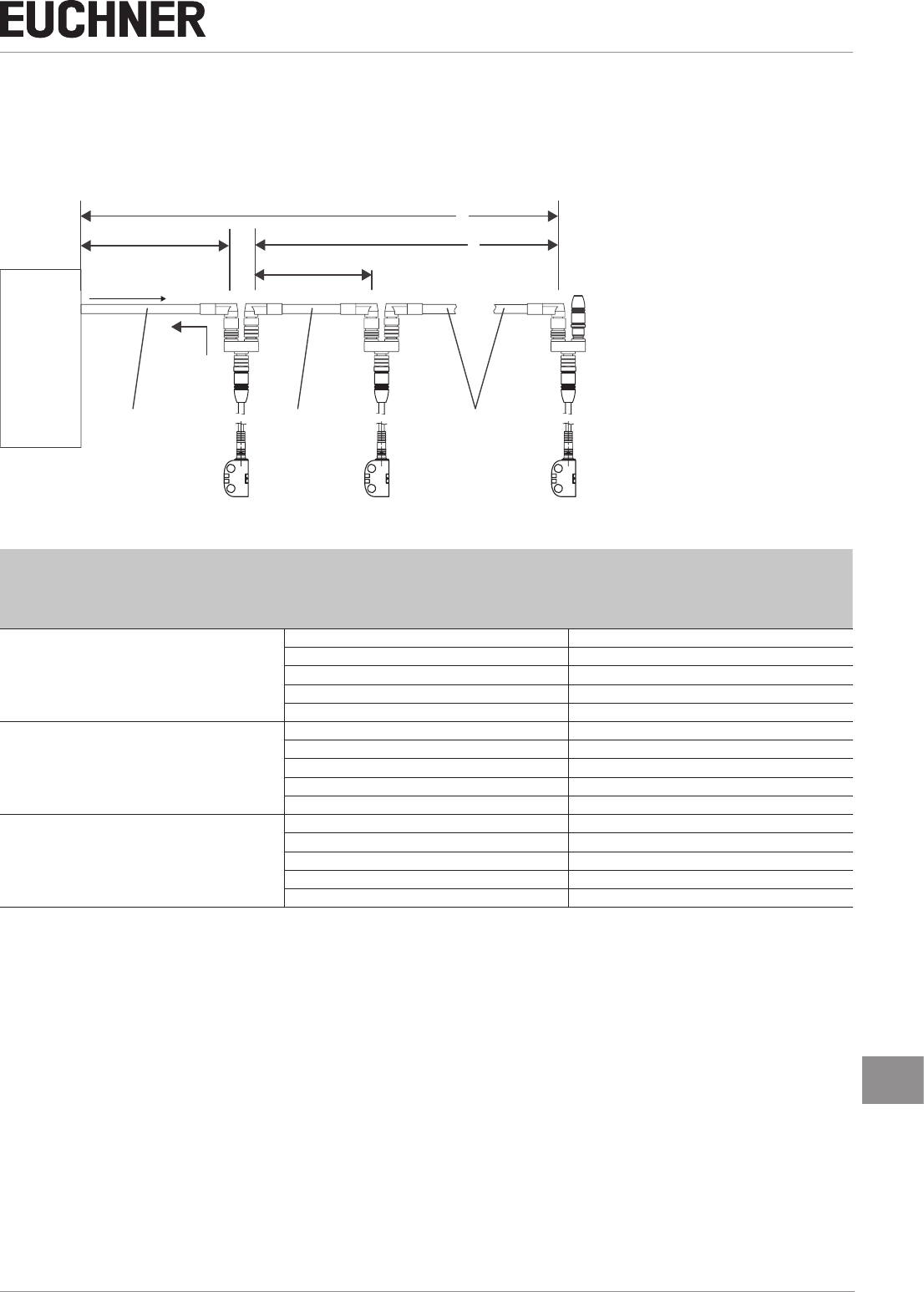
Switch chains are permitted up to a maximum overall cable length of 200m taking into account the voltage drop as a result
of the cable resistance (see table below with example data and case example). The cable length between two switches is
limited to 100m.
SPS
PLC
l1l2
l
max
=200 m
ln
umin = 24 V
5 x 0,34 mm2
5 x 0,34 mm25 x 0,34 mm2
CES-I-BR # n CES-I-BR # n-1 CES-I-BR # 1
iout
n
Max. number of switches
IOD (mA)
Possible output current per channel FO1A/FO1B
l1 (m)
Max. cable length from the last switch to the
control system
0.34 mm²
5
10 100
25 100
50 80
100 50
200 25
6
10 100
25 90
50 70
100 50
200 25
10
10 70
25 60
50 50
100 35
200 20
Contact EUCHNER in the following cases:
ÌIf you connect more than 10 switches in series.
ÌIf you plan to use a different cable design (cross-section, material, etc.).
Operating Instructions
Non-Contact Safety Switch CES-I-BR-.-C07-…
12 (translation of the original operating instructions) 2510145-02-07/18
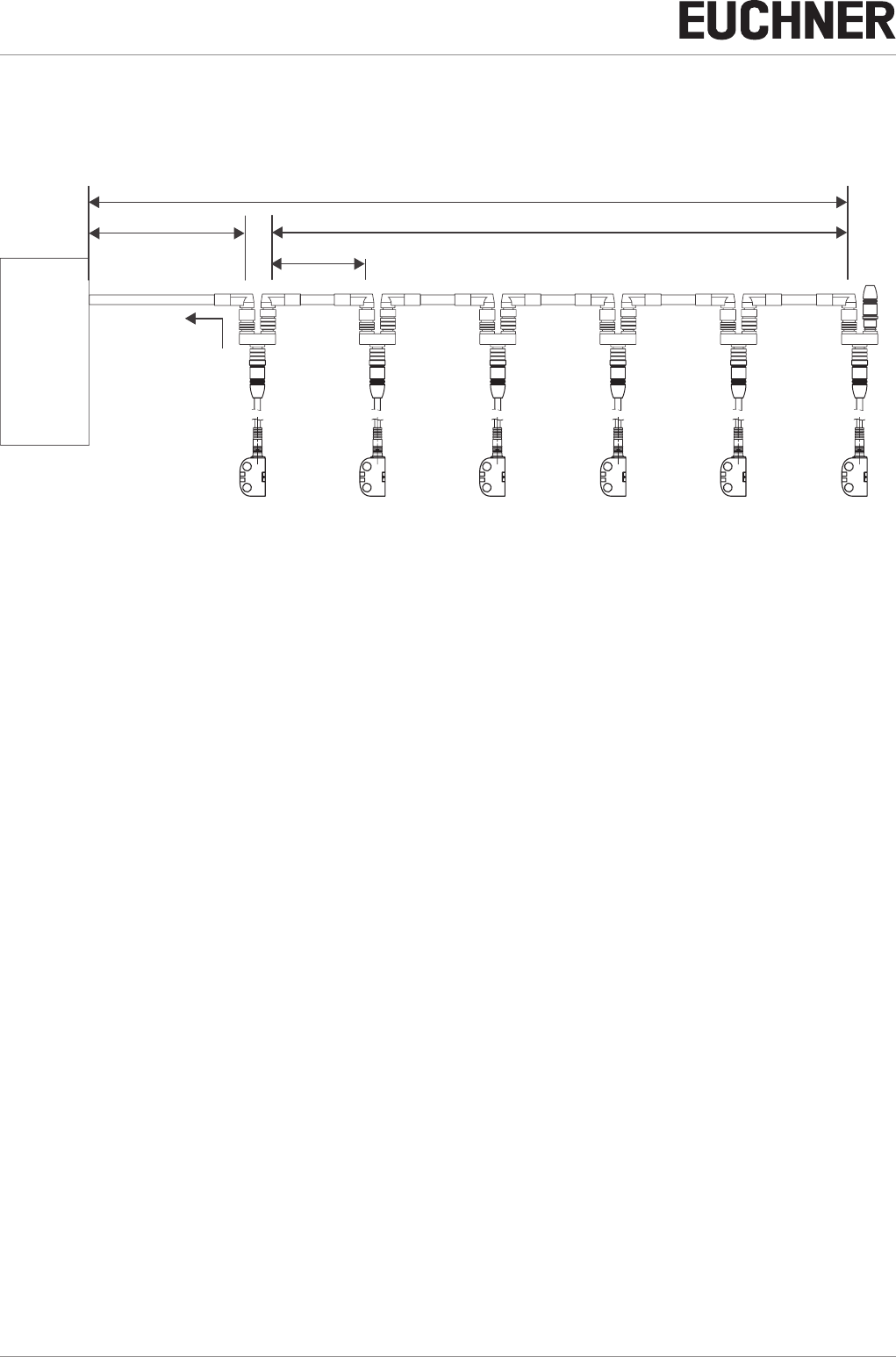
8.5.1. Determining cable lengths using the example table
Example: six switches are to be used in series. Cabling with a length of 40m is routed from a safety relay in the control
cabinet to the last switch (#6). Cables with a length of 20m each are connected between the individual safety switches.
CES-I-BR # 6
Sicherheits-
relais
Safety Relay
CES-I-BR # 5 CES-I-BR # 4 CES-I-BR # 3 CES-I-BR # 2 CES-I-BR # 1
l1 = 40 m l2 = 5 x 20 m
l
max
= 140 m
ln = 20 m
iout = min. 75 mA
Figure 1: Circuit example with six CES-I-BR
A safety relay is connected downstream which consumes 75mA at each of the two safety inputs.
All the relevant values can now be determined using the example table:
1. Select the corresponding section in the column n (max. number of switches). Here: six switches.
2. In column IOD (possible output current per channel FO1A/FO1B), nd a current greater than or equal to 75mA. Here:
100mA.
¨It is then possible to determine the maximum cable length from the last switch (#6) to the control system from column
l1. Here: a length of 50m is permitted.
Result: The desired cable length l1 of 40m is below the permitted value from the table. The overall length of the switch
chain lmax of 140m is less than the maximum value of 200m.
¨The planned application is therefore functional in this form.
13
2510145-02-07/18 (translation of the original operating instructions)
Operating Instructions
Non-Contact Safety Switch CES-I-BR-.-C07-…
EN
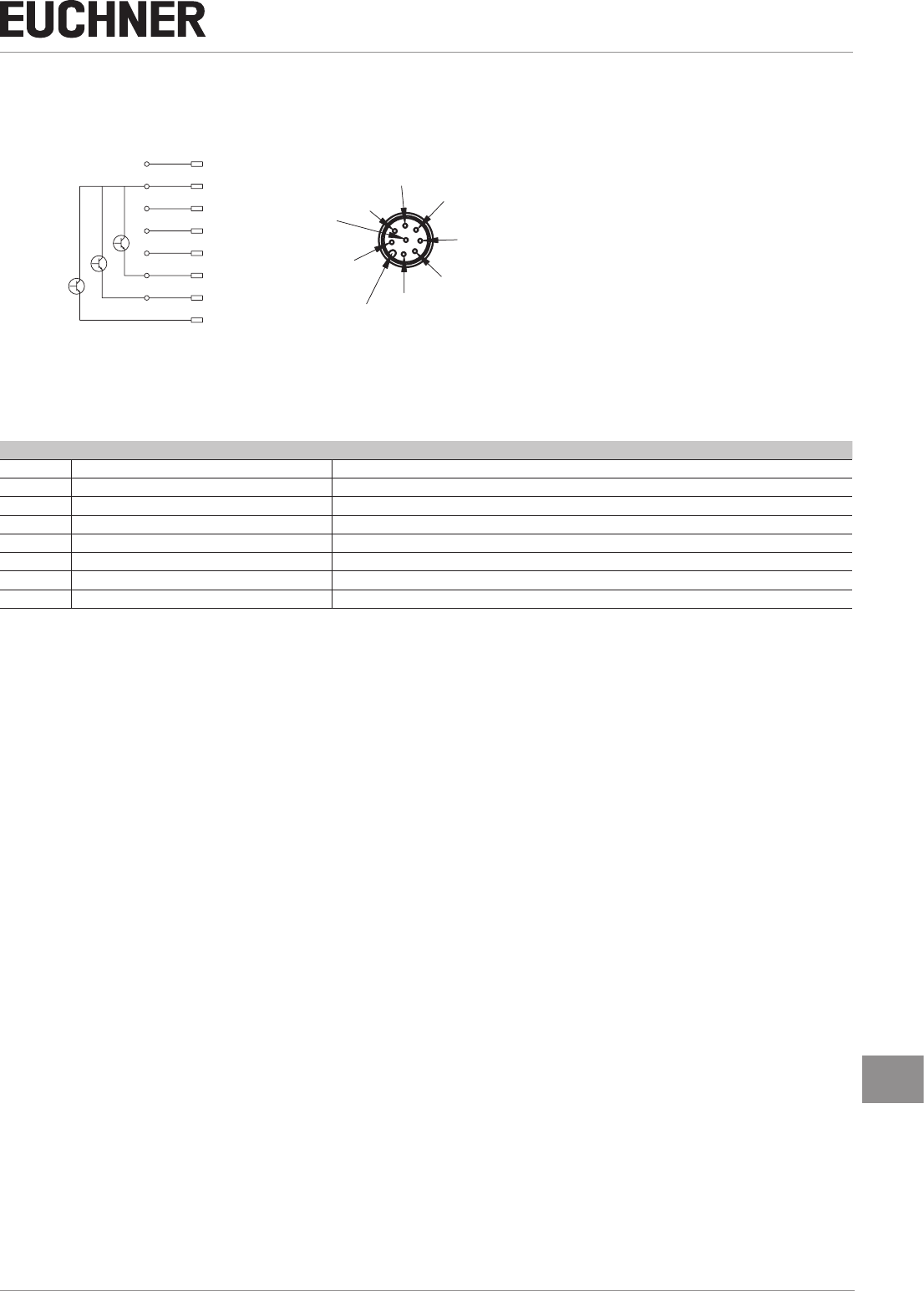
8.6. Pin assignment of safety switch CES-I-BR
coding lug
1
7
65
4
3
2
8
8
2
7
6
1
3
4
5
UB
0V
FI1A
FI1B
FO1A
FO1B
OD/C
nc
View of connection side on the safety switch
Figure 2: Pin assignment of safety switch CES-I-BR
Pin Designation Description
1 FI1B Enable input for channel 2
2 UB Power supply, DC 24 V
3 FO1A Safety output, channel 1
4 FO1B Safety output, channel 2
5OD/C Monitoring output/communication
6FI1A Enable input for channel 1
7 0V Ground, DC 0 V
8 nc n.c.
Operating Instructions
Non-Contact Safety Switch CES-I-BR-.-C07-…
14 (translation of the original operating instructions) 2510145-02-07/18
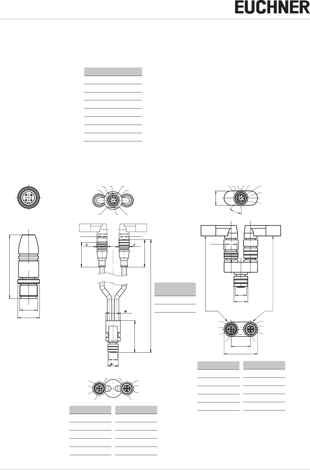
8.7. Pin assignment of Y-distributor
M12x1
max. 45
Ø 14,5
Strapping plug 097645
4-pin, plug
(gure similar)
Y-distributor
with connecting cable
111696 or 112395
Socket
pin Socket
Pin Function
X2.1 UB
X2.2 FO1A
X2.3 0V
X2.4 FO1B
X2.5 RST
Pin Function
X3.1 UB
X3.2 FI1A
X3.3 0V
X3.4 FI1B
X3.5 RST
12
12
097627
45°
15,1
485
6
312
7
35,1
20,5
1
2
4
5
33
4
2
1
5
Mx1
Ø 14,6
Mx1
( )
Y-distributor
097627
Socket
Pin assignment
of safety switch CES-I-BR
(8-pin plug)
and
Y-distributor (8-pin socket)
Pin Function
X1.1 FI1B
X1.2 UB
X1.3 FO1A
X1.4 FO1B
X1.5 OD
X1.6 FI1A
X1.7 0V
X1.8 RST
pin Socket
M
12
x1
44
45
41
15
M
12
x1
15 15
M
12
x1
33
A
B
4
8
5
6
3
1
2
7
1
2
4
5
33
4
2
1
5
Length l
Order no. Length
l [mm]
111696 200
112395 1000
Pin Function
X2.1 UB
X2.2 FO1A
X2.3 0V
X2.4 FO1B
X2.5 RST
Pin Function
X3.1 UB
X3.2 FI1A
X3.3 0V
X3.4 FI1B
X3.5 RST
15
2510145-02-07/18 (translation of the original operating instructions)
Operating Instructions
Non-Contact Safety Switch CES-I-BR-.-C07-…
EN
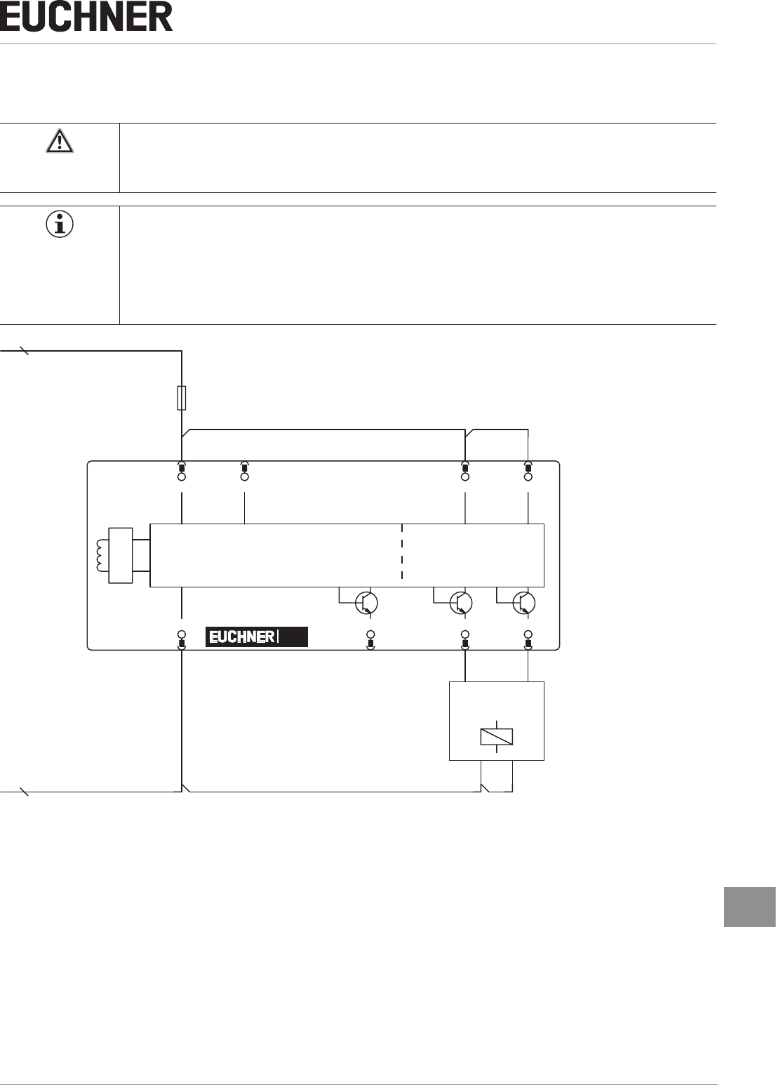
8.8. Connection of a single BR device
If a single BR device is used, connect the device as shown in Figure 3. Monitoring outputs can be routed to a control system.
WARNING
If there is a mistake, loss of the safety function due to incorrect connection.
ÌTo ensure safety, both safety outputs (FO1A and FO1B) must always be evaluated.
Important!
The example shows only an excerpt that is relevant for connection of the CES system. The example
illustrated here does not show complete system planning. The user is responsible for safe integration
into the overall system. Detailed application examples can be found at www.euchner.com. Simply
enter the order number in the search box. All available connection examples for the device can be
found in “Downloads.”
Safety
Outputs
Monitoring
Output
Read Head
Safety Inputs
Connected
load
24 V DC
GND
-F1
+UB
2
FI1A
6
FI1B
1
0V
7
OD/C
5
FO1A
3
FO1B
4
nc
8
CES
Figure 3: Connection example for separate operation of a CES-I-BR-…

Operating Instructions
Non-Contact Safety Switch CES-I-BR-.-C07-…
16 (translation of the original operating instructions) 2510145-02-07/18
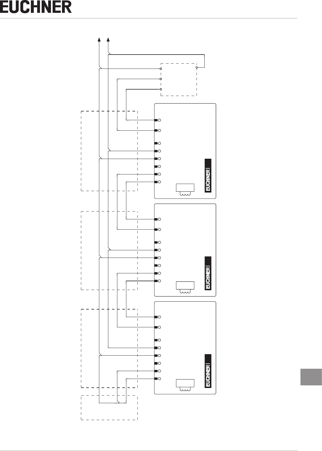
8.9. Connection of several devices in a switch chain
Important!
ÌA BR switch chain may contain a maximum of 20 safety switches.
ÌThe example shows only an excerpt that is relevant for connection of the CES system. The exam-
ple illustrated here does not show complete system planning. The user is responsible for safe inte-
gration into the overall system. Detailed application examples can be found at www.euchner.com.
Simply enter the order number in the search box. You will nd all available connection examples for
the device in Downloads.
The series connection is shown here based on the example of the version with plug connectors M12. The switches are con-
nected one behind the other with the aid of pre-assembled connection cables and Y-distributors. If a safety door is opened or
if a fault occurs on one of the switches, the system shuts down the machine. A higher-level control system cannot, however,
detect which safety door is open or on which switch a fault has occurred with this connection technology.
The series connection can also be realized via additional terminals in a control cabinet.
The safety outputs are permanently assigned to the respective safety inputs of the downstream switch. FO1A must be routed
to FI1A and FO1B to FI1B. If the connections are interchanged (e.g. FO1A to FI1B), the device will switch to the fault state.
17
2510145-02-07/18 (translation of the original operating instructions)
Operating Instructions
Non-Contact Safety Switch CES-I-BR-.-C07-…
EN
Safety Outputs
Safety Inputs
Y-distributor Y-distributor Y-distributor
Terminating plug
Eval Unit
Safety Outputs
Safety Inputs Safety Inputs
Safety Outputs
Read Head
5
OD/C
4
FO1B
2
+UB
8
nc
6
FI1A
1
FI1B
7
0V
5
OD/C
3
FO1A
4
FO1B
2
+UB
8
nc
6
FI1A
1
FI1B
7
0V
3
FO1A
4
FO1B
2
+UB
8
nc
6
FI1A
1
FI1B
7
0V
5
OD/C
3
FO1A
0V
24
V
CESCESCES
Read Head
Read Head
Figure 4: Connection example for series connection

Operating Instructions
Non-Contact Safety Switch CES-I-BR-.-C07-…
18 (translation of the original operating instructions) 2510145-02-07/18
8.10. Notes on operation with safe control systems
Please observe the following requirements for connection to safe control systems:
ÌUse a common power supply for the control system and the connected safety switches.
ÌA pulsed power supply must not be used for UB. Tap the supply voltage directly from the power supply unit. If the supply
voltage is connected to a terminal of a safe control system, this output must provide sufcient electrical current.
ÌAlways connect inputs FI1A and FI1B directly to a power supply unit or to outputs FO1A and FO1B of another EUCHNER
BR device (series connection). Pulsed signals must not be present at inputs FI1A and FI1B.
ÌThe safety outputs (FO1A and FO1B) can be connected to the safe inputs of a control system. Prerequisite: the input
must be suitable for pulsed safety signals (OSSD signals, e.g. from light grids). The control system must tolerate test
pulses on the input signals. This normally can be set up by parameter assignment in the control system. Observe the
notes of the control system manufacturer. For the test-pulse duration of your safety switch, please refer to chapter 11.
Technical data on page 22.
A detailed example of connecting and setting the parameters of the control system is available for many devices at
www.euchner.com in the area Download » Applications » CES. The features of the respective device are dealt with there in
greater detail.
19
2510145-02-07/18 (translation of the original operating instructions)
Operating Instructions
Non-Contact Safety Switch CES-I-BR-.-C07-…
EN
9. Commissioning
9.1. LED displays
You will nd a detailed description of the signal functions in chapter 10. System status table CES‑I‑BR‑… on page 21.
LED Color
STATE green
DIA red
9.2. Teach-in function for actuator (only for unicode evaluation)
The actuator must be allocated to the safety switch using a teach-in function before the system forms a functional unit.
During a teach-in operation, the safety outputs and the monitoring output OD/C are switched off, i.e. the system is in the
safe state.
Tip!
It is recommended to perform the teach-in operation prior to mounting. Mark switches and actuators
that belong together in order to avoid confusion. For devices to be connected in series, we recommend
performing the teach-in operation separately for each device prior to series connection.
Important!
ÌThe teach-in operation may be performed only if the device functions awlessly. The red DIA LED
must not be illuminated.
ÌThe safety switch disables the code of the previous actuator if teach-in is carried out for a new
actuator. Teach-in is not possible again immediately for this actuator if a new teach-in operation is
carried out. The disabled code is released again in the safety switch only after a third code has
been taught in.
ÌThe safety switch can be operated only with the last actuator taught in.
ÌThe number of teach-in operations is unlimited.
ÌIf the switch detects the actuator that was most recently taught in when in the teach-in standby
state, this state is ended immediately and the switch changes to normal operation.
ÌIf the actuator to be taught in is within the operating distance for less than 30s, it will not be acti-
vated and the most recently taught in actuator will remain saved.
9.2.1. Preparing device for the teach-in operation and teaching in actuator
1. Apply operating voltage to the safety switch.
¨The green LED ashes quickly (approx. 5Hz)
A self-test is performed during this time (approx. 5s). After this, the LED ashes cyclically three times and signals that
it is in standby state for teach-in.
Standby state for teach-in remains active for approx. 3 minutes. On switches that have not been taught in, teach-in
standby is unlimited.
2. Move new actuator to the read head (observe distance < Sao).
¨Teach-in operation starts, green LED ashes (approx. 1 Hz). During the teach-in operation, the safety switch checks
whether the actuator is a disabled actuator. After successful teach-in, the STATE and DIA LEDs ash alternately. The new
code has now been stored, and the old code is disabled. The teach-in operation takes approx. 30s.
3. Disconnect safety switch from the operating voltage for 3 seconds.
¨The switch is in normal operation after the self-test.
LEDs

Operating Instructions
Non-Contact Safety Switch CES-I-BR-.-C07-…
20 (translation of the original operating instructions) 2510145-02-07/18
9.3. Functional check
WARNING
Danger of fatal injury as a result of faults in installation and functional check.
ÌBefore carrying out the functional check, make sure that there are no persons in the danger zone.
ÌObserve the valid accident prevention regulations.
9.3.1. Electrical function test
After installation and any fault, the safety function must be fully checked. Proceed as follows:
1. Switch on operating voltage.
¨The machine must not start automatically.
¨The safety switch carries out a self-test. The green STATE LED ashes for 5s at 5Hz. The green STATE LED then ashes
at regular intervals.
2. Close all guards.
¨The machine must not start automatically.
¨The green STATE LED illuminates continuously.
3. Enable operation in the control system.
4. Open the guard.
ÌThe machine must switch off and it must not be possible to start it as long as the guard is open.
ÌThe green STATE LED ashes at regular intervals.
Repeat steps 2-4 for each guard.
21
2510145-02-07/18 (translation of the original operating instructions)
Operating Instructions
Non-Contact Safety Switch CES-I-BR-.-C07-…
EN
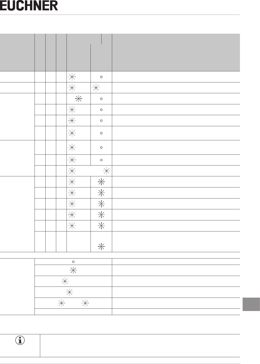
10. System status table CES-I-BR-…
operating mode
Actuator/door po-
sition
Safety outputs FO1A
and FO1B
Monitoring output
OD/C
LED indicator
Output
State
STATE (green)
DIA (red)
Self-test X off off 5Hz
(5s) Self-test after power-up
Hot plugging X off off 5Hz
(5s) 1 x
Normal operation
closed on on Normal operation, door closed, safety outputs on the preceding device in the switch chain
switched on
closed off on 1 x
inverse
Normal operation, door closed, safety outputs on the preceding device in the switch chain
switched off
open off off 1 x Normal operation, door open
closed on on
ashes
quickly
2Hz
Normal operation, door closed, actuator in the limit range ¨ Re-adjust door
Teach-in operation
(only unicode)
open off off 3 x
Door open, device is ready for teach-in for another actuator (only short time after pow-
er-up). Switches that have not been taught in remain in teach-in standby until the teach-in
operation starts.
closed off on 1 Hz Teach-in operation
X off X ¨ Positive acknowledgment after completion of teach-in operation
Fault display
X off X 1 x Fault in the teach-in operation (only unicode), actuator removed from the operating dis-
tance prior to the end of the teach-in operation or faulty actuator detected.
X off off 2 x Input fault (e.g. missing test pulses, illogical switch state from previous switch in the
switch chain)
X off off 3 x Defective or incompatible actuator (e.g. fault in code or code not readable)
X off off 4 x Output fault (e.g. short circuits, loss of switching ability)
X off X 5 x Environment error (e.g.temperature or operating voltage in the limit range)
X off off X
X
or Internal fault (e.g. over-temperature, over/undervoltage or component faulty)
Key to symbols
LED not illuminated
LED illuminated
5Hz (5s) LED ashes for 5 at 5Hz
3 x LED ashes three times, and this is then repeated
¨ LEDs ash alternately
X Any state
After the cause has been remedied, faults can generally be reset by opening and closing the guard. If the fault is still displayed
afterward, briey interrupt the power supply. Please contact the manufacturer if the fault could not be reset after restarting.
Important!
If you do not nd the displayed device status in the system status table, this indicates an internal device
fault. In this case, you should contact the manufacturer.
Operating Instructions
Non-Contact Safety Switch CES-I-BR-.-C07-…
22 (translation of the original operating instructions) 2510145-02-07/18
11. Technical data
NOTICE
If a data sheet is included with the product, the information on the data sheet applies.
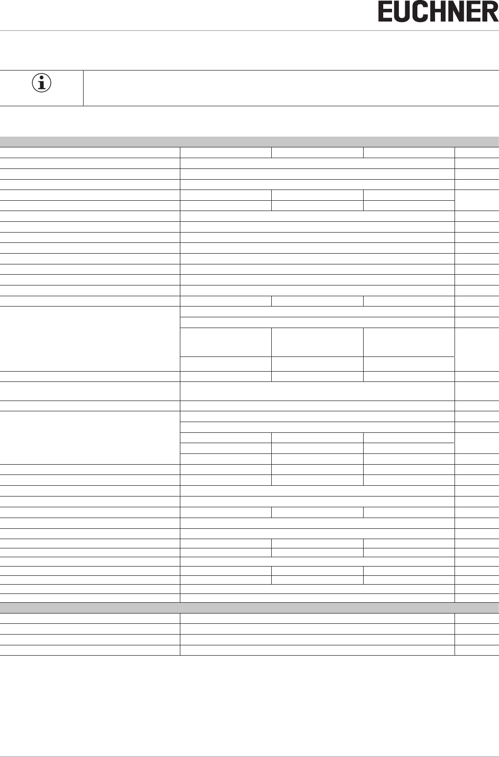
11.1. Technical data of safety switch CES-I-BR-C07-…
Parameter Value Unit
min. typ. max.
Housing material PBT plastic
Dimensions 40 x 26.5 x 18 mm
Weight (device without connection cable) 0.08 kg
Ambient temperature at UB = DC 24 V - 25 - + 55 °C
Storage temperature - 40 - + 70
Degree of protection IP 65/IP 67/IP 69/IP 69K
Safety class III
Degree of contamination 3
Installation position Any
Installation method Non-ush
Connection Plug connector M12, 8-pin
Operating voltage UB (regulated, residual ripple < 5%) 24 ± 15% (PELV) V DC
Current consumption 40 mA
External fuse (operating voltage) 0.25 - 8 A
Safety outputs FO1A/FO1B Semiconductor outputs, p-switching, short circuit-proof
- Output voltage U(FO1A)/U(FO1B) 1)
HIGH U(FO1A)
UB-1.5 - UBV DC HIGH U(FO1B)
LOW U(FO1A)/U(FO1B) 0 1
Switching current per safety output 1 - 150 mA
Utilization category according to ENIEC60947-5-2 DC-13 24 V 150 mA
Caution: outputs must be protected with a free-wheeling diode in case of inductive loads.
Off-state current Ir≤ 0.25 mA
Monitoring output OD/C 1) p-switching, short circuit-proof
- Output voltage
HIGH UB-1.5 - UBV DC
LOW 0 - 1
- Switching current 1 - 50 mA
Rated insulation voltage Ui- - 300 V
Rated impulse withstand voltage Uimp - - 1.5 kV
Conditional short-circuit current 100 A
Resilience to vibration Acc. to ENIEC60947-5-2
Switching frequency - - 1 Hz
Repeat accuracy R ≤ 10 %
EMC protection requirements Acc. to ENIEC60947-5-3
Ready delay - 5 - s
Risk time for single device - - 125 ms
Risk time delay per device 10 ms
Switch-on time - - 400 ms
Discrepancy time - - 10 ms
Test-pulse duration 0.3 ms
Test-pulse interval Approx. 100 ms
Reliability values acc. to ENISO13849-1:2015
Category 4
Performance Level PL e
PFHD6 x 10 -10 / h
Mission time 20 years
1) Values at a switching current of 50 mA without taking into account the cable length.

23
2510145-02-07/18 (translation of the original operating instructions)
Operating Instructions
Non-Contact Safety Switch CES-I-BR-.-C07-…
EN
11.1.1. Radio frequency approvals
FCC ID: 2AJ58-01
IC: 22052-01
FCC/IC-Requirements
This device complies with part 15 of the FCC Rules and with Industry Canada’s licence-exempt RSSs. Operation is subject
to the following two conditions:
1) This device may not cause harmful interference, and
2) this device must accept any interference received, including interference that may cause undesired operation.
Changes or modications not expressly approved by the party responsible for compliance could void the user‘s authority
to operate the equipment.
NOTE: This equipment has been tested and found to comply with the limits for a Class A digital device, pursuant to part 15 of
the FCC Rules. These limits are designed to provide reasonable protection against harmful interference when the equipment
is operated in a commercial environment. This equipment generates, uses, and can radiate radio frequency energy and, if
not installed and used in accordance with the instruction manual, may cause harmful interference to radio communications.
Operation of this equipment in a residential area is likely to cause harmful interference in which case the user will be required
to correct the interference at his own expense.
Le présent appareil est conforme aux CNR d’Industrie Canada applicables aux appareils radio exempts de licence. L’exploi-
tation est autorisée aux deux conditions suivantes :
(1) l’appareil ne doit pas produire de brouillage, et
(2) l’utilisateur de l’appareil doit accepter tout brouillage radioélectrique subi, même si le brouillage est susceptible d’en
compromettre le fonctionnement.
Operating Instructions
Non-Contact Safety Switch CES-I-BR-.-C07-…
24 (translation of the original operating instructions) 2510145-02-07/18
11.1.2. Typical system times
Please refer to the technical data for the exact values.
Ready delay: After switching on, the device carries out a self-test. The system is ready for operation only after this time.
Switch-on time of safety outputs: The max. reaction time ton is the time from the moment when the actuator is in the
operating distance to the moment when the safety outputs switch on.
Simultaneity monitoring, safety inputs FI1A/FI1B: If the safety inputs have different switching states over a certain
time, the safety outputs (FO1A and FO1B) will be switched off. The devices switches to fault state.
Risk time according to EN 60947-5-3: If an actuator moves outside the operating distance, the safety outputs (FO1A
and FO1B) are switched off after the risk time at the latest.
If several devices are operated in a series connection, the risk time of the overall device chain will increase with each device
added. Use the following calculation formula:
tr=tr,e+(nxtl)
tr = Total risk time
tr,e = Risk time, single device (see technical data)
tl = Risk time delay per device
n = Number of additional devices (total number -1)
Discrepancy time: The safety outputs (FO1A and FO1B) switch with a slight time offset. They have the same signal state
no later than after the discrepancy time.
Test pulses at the safety outputs: The device generates its own test pulses on the safety outputs (FO1A and FO1B). A
downstream control system must tolerate these test pulses.
This can usually be set up in the control systems by parameter assignment. If parameter assignment is not possible for your
control system or if shorter test pulses are required, please contact our support organization.
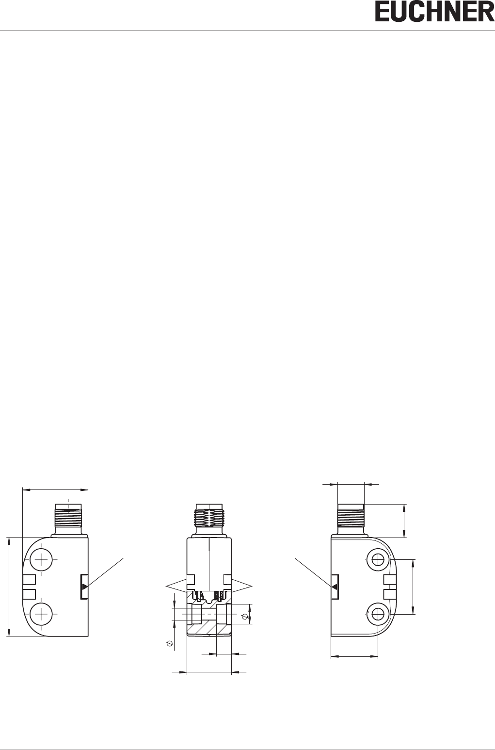
11.1.3. Dimension drawing for safety switch CES-I-BR-C07-…
13,5
M12x1
22 ±0,1
19
8
4,8
6
18
40
26,5
LEDs
Active face Active face
Plug connector
LEDs
25
2510145-02-07/18 (translation of the original operating instructions)
Operating Instructions
Non-Contact Safety Switch CES-I-BR-.-C07-…
EN
11.2. Technical data of actuator CES-A-BTN-C07-…
Parameter Value Unit
min. typ. max.
Housing material PBT plastic
Dimensions 42 x 25 x 18 mm
Weight 0.03 kg
Ambient temperature - 40 - + 70 °C
Degree of protection IP 65/IP 67/IP 69/IP 69K
Installation position Active face opposite read head
Power supply Inductive via read head
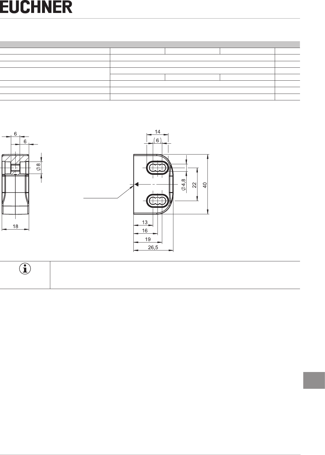
11.2.1. Dimension drawing
Active face
NOTICE
ÌTwo safety screws M4x20 included.
ÌCovers are included.
Operating Instructions
Non-Contact Safety Switch CES-I-BR-.-C07-…
26 (translation of the original operating instructions) 2510145-02-07/18
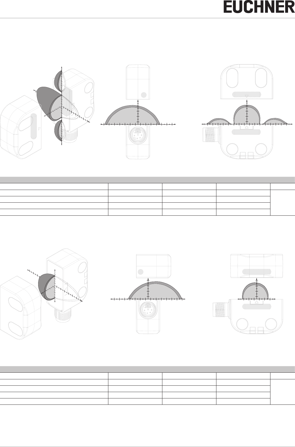
11.2.2. Operating distances and approach directions
(only in conjunction with actuator CES-A-BTN-C07)
Typical operating distance in approach direction A
18 26
-26
-Z Z
X
14
Y
-Y
-2
-6
-10
-26
-30
6
10
14
22
26
30
214
2
6
210
622
-14
-18
-22
10
18
X
X
Y
2
6
10
14
18
22
26
30
-2
-6
-10
-14
-18
-22
-26
-30
-2
Z
2
6
10
14
2
6
10
14
-6
-10
-14
-18
-22
-26
2
6
10
14
18
22
26
Switching distances on approach in x direction without center offset (z,y=0)
Parameter Value Unit
min. typ. max.
Switch-on distance - 13 -
mm
Assured switch-on distance sao 10 - -
Switching hysteresis 1) 1 2 -
Assured switch-off distance sar - - 20
Typical operating distance in approach direction B
18 26
2614
10 22
-22
-26 -18
-2
-6
-10
6
10
2
14
2
6
10
-Z Z
Y
X
-Y
X
Y
X
Z
2
6
10
14
2
6
10
14
2
6
10
-2
-6
-10
2
6
10
14
18
22
26
-2
-6
-10
-14
-18
-22
-26
Switching distances on approach in x direction without center offset (z,y=0)
Parameter Value Unit
min. typ. max.
Switch-on distance - 13 -
mm
Assured switch-on distance sao 9 - -
Switching hysteresis 1) 1 2 -
Assured switch-off distance sar - - 20
27
2510145-02-07/18 (translation of the original operating instructions)
Operating Instructions
Non-Contact Safety Switch CES-I-BR-.-C07-…
EN
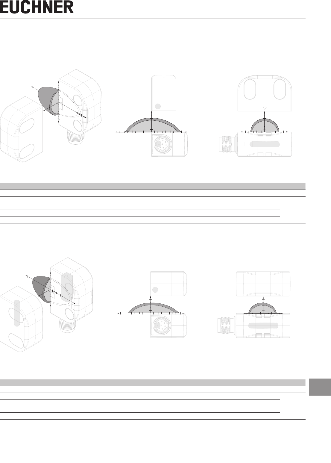
Typical operating distance in approach direction C
Y
-Y
-2
-6
-10
6
10
14
2
-14
X
14
2
6
10
18
214
10
622
-22
-Z Z
X
Y
2
6
10
14
-2
2
6
10
2
6
10
-6
-10
-14
2
6
10
14
18
22
-2
-6
-10
-14
-18
-22
X
Z
Switching distances on approach in x direction without center offset (z,y=0)
Parameter Value Unit
min. typ. max.
Switch-on distance - 7 -
mm
Assured switch-on distance sao 3 - -
Switching hysteresis 1) 1 2 -
Assured switch-off distance sar - - 17
Typical operating distance in approach direction D
Z
26
-2
2
-6
-10
2
6
10
-Y
X
10 14 18
6
10
22
-22 -18
Y
-Z
X
X
ZY
2
6
10
-2
-6
-10
2
6
10
14
18
22
-2
-6
-10
-14
-18
-22
2
6
10
2
6
10
Switching distances on approach in x direction without center offset (z,y=0)
Parameter Value Unit
min. typ. max.
Switch-on distance - 7 -
mm
Assured switch-on distance sao 2 - -
Switching hysteresis 1) 1 2 -
Assured switch-off distance sar - - 17
Operating Instructions
Non-Contact Safety Switch CES-I-BR-.-C07-…
28 (translation of the original operating instructions) 2510145-02-07/18
11.3. Technical data of actuator CES-A-BDN-06-158210
Parameter Value Unit
min. typ. max.
Housing material Macromelt PA-based plastic
Dimensions 26 x ∅ 6 mm
Weight 0.005 kg
Ambient temperature - 40 - + 70 °C
Degree of protection acc. to ENIEC60529 IP 65/IP 67/IP 69/IP 69K 1)
Installation position Active face opposite read head
Power supply Inductive via read head
1) With ush installation
11.3.1. Dimension drawing
Installation options
26
0
+
0,5
Ø
30
* min.
30
*
30
*
6,1
0
+
0,1
6
* Metal-free zone
Operating distance
Approach
direction
CAUTION
ÌDo not mount at temperatures below 0 °C.
ÌThe actuator can be damaged during mounting.
11.3.2. Switching distances
Operating distance for center offset m = 0
Approach direction Parameter Value Unit
Amin. typ. max.
z
x
Switch-on distance - 16 -
mm
Assured switch-on distance sao 1) 13 - -
Switching hysteresis 1) 1 2 -
Assured switch-off distance sar
- in x direction - - 24
1) The values apply to surface installation of the actuator
Approach direction Parameter Value Unit
Cmin. typ. max.
z
x
Switch-on distance - 11 -
mm
Assured switch-on distance sao 1) 6 - -
Switching hysteresis 1) 1 2 -
Assured switch-off distance sar
- in x direction - - 21
1) The values apply to surface installation of the actuator
29
2510145-02-07/18 (translation of the original operating instructions)
Operating Instructions
Non-Contact Safety Switch CES-I-BR-.-C07-…
EN
12. Ordering information and accessories
Tip!
Suitable accessories, e.g. cables or assembly material, can be found at www.euchner.com. To order,
enter the order number of your item in the search box and open the item view. Accessories that can
be combined with the item are listed in “Accessories.”
13. Inspection and service
WARNING
Loss of the safety function because of damage to the device.
ÌIn case of damage, the entire device must be replaced.
ÌOnly accessories or spare parts that can be ordered from EUCHNER may be replaced.
Regular inspection of the following is necessary to ensure trouble-free long-term operation:
ÌCheck the switching function (see chapter 9.3. Functional check on page 20)
ÌCheck the secure fastening of the devices and the connections
ÌCheck for soiling
No servicing is required. Repairs to the device are only allowed to be made by the manufacturer.
NOTICE
The year of manufacture can be seen in the bottom right corner. The current version number in the
format (VX.X.X) can also be found on the device.
14. Service
If service support is required, please contact:
EUCHNER GmbH + Co. KG
Kohlhammerstraße 16
70771 Leinfelden-Echterdingen
Service telephone:
+49 711 7597-500
E-mail:
support@euchner.de
Internet:
www.euchner.com

Operating Instructions
Non-Contact Safety Switch CES-I-BR-.-C07-…
30 (translation of the original operating instructions) 2510145-02-07/18
15. Declaration of conformity
Declaration will be added after approval.

31
2510145-02-07/18 (translation of the original operating instructions)
Operating Instructions
Non-Contact Safety Switch CES-I-BR-.-C07-…
EN
Euchner GmbH + Co. KG
Kohlhammerstraße 16
70771 Leinfelden-Echterdingen
info@euchner.de
www.euchner.com
Edition:
2510145-02-07/18
Title:
Operating Instructions Non-Contact Safety Switch
CES-I-BR-.-C07-…
(translation of the original operating instructions)
Copyright:
© EUCHNER GmbH + Co. KG, 07/2018
Subject to technical modications; no responsibility is accept-
ed for the accuracy of this information.