EUCHNER KG 02 Safety Switch User Manual
EUCHNER GmbH Co.KG Safety Switch
UserManual.wiki
>
EUCHNER KG
>
02 User Manual
>
user manual
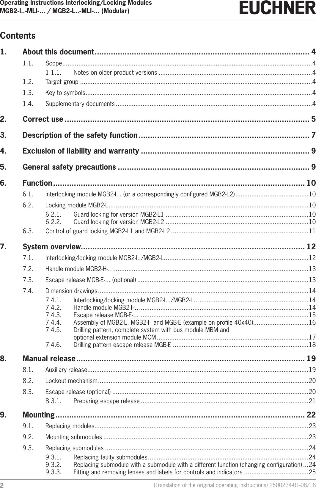
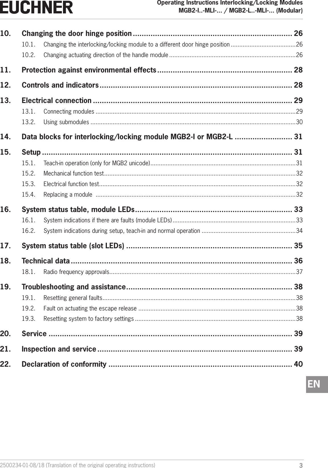
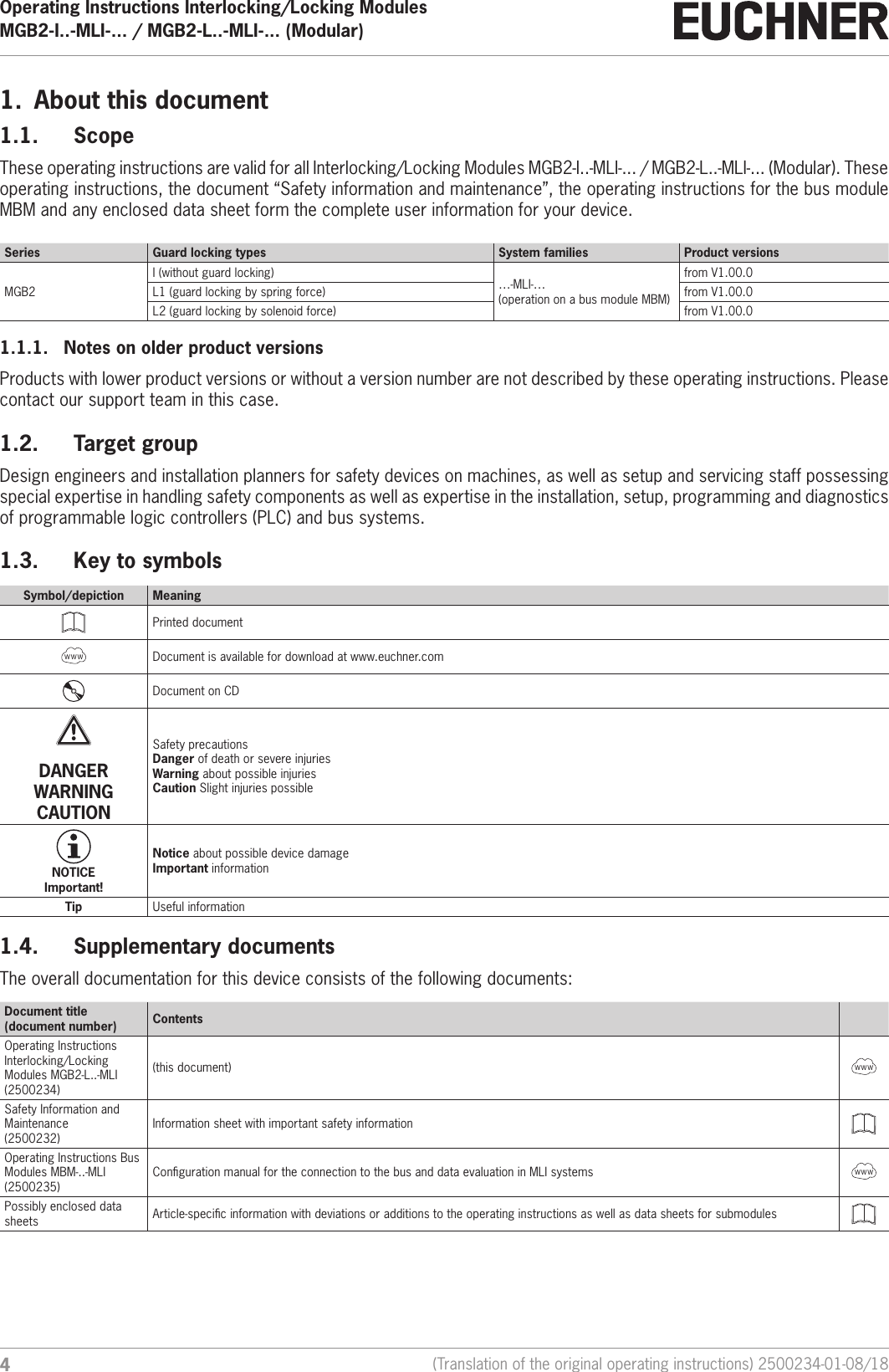
Contents
1.
user manual
2.
user manual Safety Information
user manual
Navigation menu
Upload a User Manual
Namespaces
Wiki Guide
HTML
PDF
Info
Views
User Manual
Discussion / Help
Navigation