EUROTECH MRG1011 REGATE 10-11-16 User Manual My
EUROTECH SpA REGATE 10-11-16 My
UserManual.wiki
>
EUROTECH
>
MRG1011 User Manual
User Manual
Navigation menu
Upload a User Manual
Namespaces
Wiki Guide
HTML
PDF
Info
Views
User Manual
Discussion / Help
Navigation

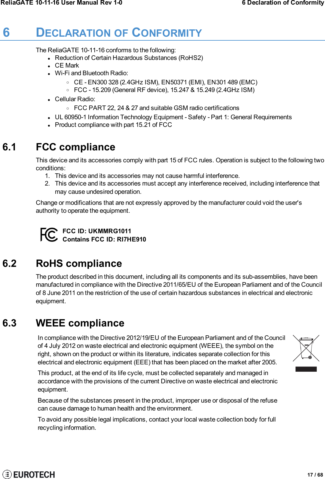
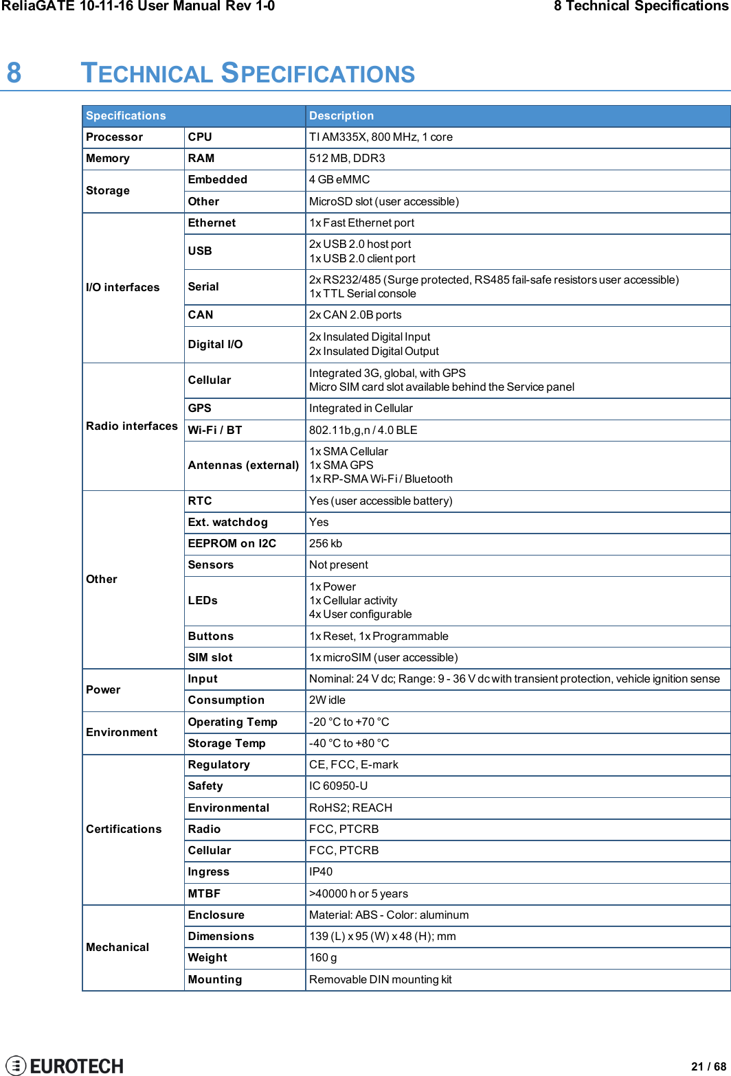
![ReliaGATE 10-11-16 User Manual Rev 1-0 7 EMI / EMC requirements7 EMI / EMC REQUIREMENTS7.1 EN 61000-6-2:2005 Immunity Requirements, B criteriaRadiated Emission Limits at 10 metersIEC 61000-4-2: ED. 2.0 2008Electrostatic Discharge±4 kV contact discharge; ±8 kV air dischargeIEC 61000-4-3:2006 +A1:2007RF Electromagnetic Field10 V/m, 80 – 1000 MHz, 1.4 – 2 GHz, 3 V/m, 2.0 – 2.7 GHz,1V/m 80% 1 kHz AMIEC 61000-4-4: ED. 2, 2004Electrical Fast Transient/BurstIEC 61000-4-6: ED 3.0, 2008RF Common ModeDC power ports, ±2 kVSignal ports, ±1 kV, 0.15 – 80 MHz, 10 Vrms, 80% 1 kHz AMDC power ports 0.15 – 80 MHz, 10 Vrms, 80% 1 kHz AMSignal ports: 0.15 – 80 MHz, 10 Vrms, 80% 1 kHz AMFunctional earth ports 0.15 – 80 MHz, 10 Vrms, 80% 1 kHz AMIEC 61000-4-8 :93+A1:01 Power Fre-quency Magnetic Field30 Arms/mContinuous at 60 Hz7.2 EN 61000-6-4:2001 Radiated DisturbanceRadiated Emission Limits at 10 metersFrequency band [MHz] Class A Quasi-Peak limits, [dBμV/m]30 – 230 40230 – 1000 477.3 EN 61000-6-4:2007 Conducted DisturbanceFrequency band [MHz] Limit [dBμV]Quasi-Peak Average0.15 – 0.50 79 660.50 – 5.00 73 605.00 – 30.00 73 6019 / 68](https://usermanual.wiki/EUROTECH/MRG1011/User-Guide-2939376-Page-19.png)

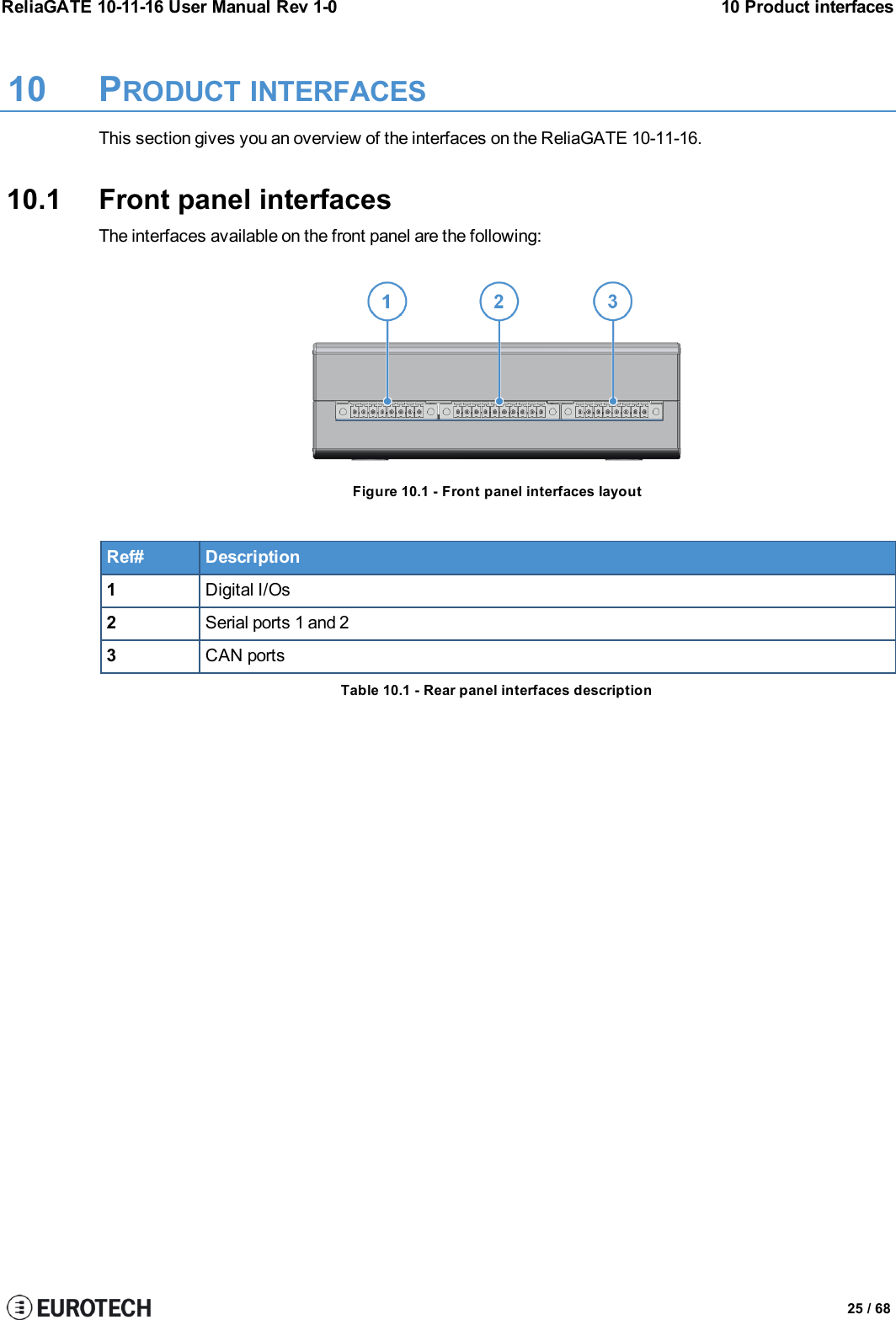

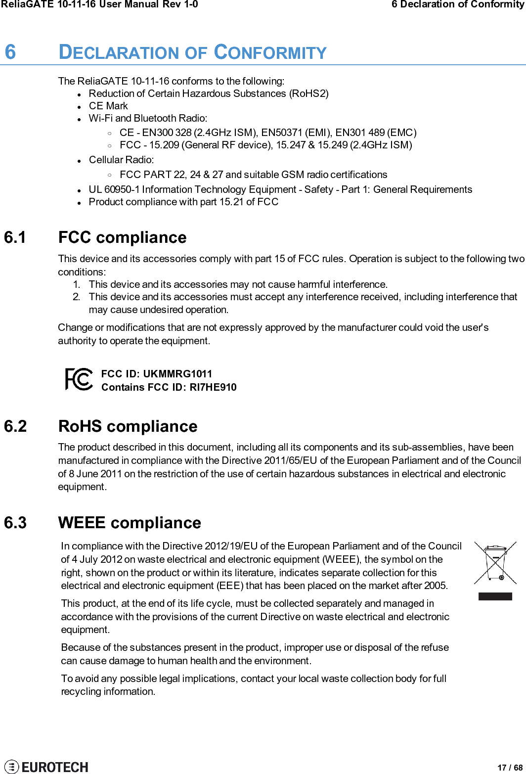
![ReliaGATE 10-11-16 User Manual Rev 1-0 11 Interfaces in detail11.5 Wi-Fi and BluetoothThe ReliaGATE 10-11-16 includes a Wi-Fi & Bluetooth (BT) module and an external antenna connection tofully implement Wi-Fi 802.11b/g/n and Bluetooth 4.0 BLE functions.The circuitry allows for Wi-Fi and Bluetooth coexistence.11.5.1 Antenna specificationsConnector Female RP-SMAMating connector Male RP-SMA11.5.2 Wi-Fi specificationslIntegrated 2.4 & 5G GHz Power Amplifier (PA) for WLAN solutionlWLAN Baseband Processor and RF transceiver Supporting IEEE Std 802.11b/g/nlWLAN 2.4GHz SISO (20/40 MHz channels)l2.4-GHz MRC Support for Extended RangelBaseband Processor:oIEEE Std 802.11a/b/g/n data rates and IEEE Std 802.11n data rates with 20 or 40 MHzSISO.lFully calibrated system. Production calibration not required.lMedium Access Controller (MAC):oEmbedded ARM™ Central Processing Unit (CPU)oHardware-Based Encryption/Decryption using 64-, 128-, and 256-Bit WEP, TKIP or AESKeys,oSupports requirements for Wi-Fi Protected Access (WPA and WPA2.0) and IEEE Std802.11i [includes hardware-accelerated Advanced Encryption Standard (AES)]oDesigned to work with IEEE Std 802.1xlIEEE Std 802.11d,e,h,i,k,r PICS compliant.lNew advanced co-existence scheme with BT/BLE/ANT.l2.4 GHz Radio:oInternal LNA and PAoSupports: IEEE Std 802.11a, 802.11b, 802.11g and 802.11nlSupports 4 bit SDIO host interface, including high speed (HS) and V3 modes11.5.3 Bluetooth specificationslSupports Bluetooth 4.0 as well as CSA2lIncludes concurrent operation and built -in coexisting and prioritization handling of Bluetooth, BLE,ANT, audio processing and WLANlDedicated Audio processor supporting on chip SBC encoding + A2DP:oAssisted A2DP (A3DP) support - SBC encoding implemented internallyoAssisted WB-Speech (AWBS) support - modified SBC codec implemented internally11.5.4 BLE specificationslFully compliant with BT4.0 BLE dual mode standardlSupport for all roles and role-combinations, mandatory as well as optionallSupports up to 10 BLE connectionslIndependent buffering for LE allows having large number of multiple connections without affectingBR/EDR performance37 / 68](https://usermanual.wiki/EUROTECH/MRG1011/User-Guide-2939376-Page-37.png)


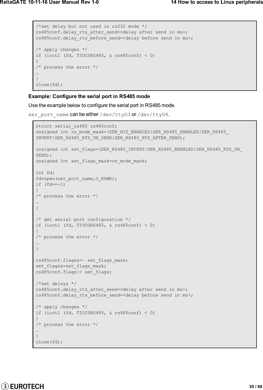
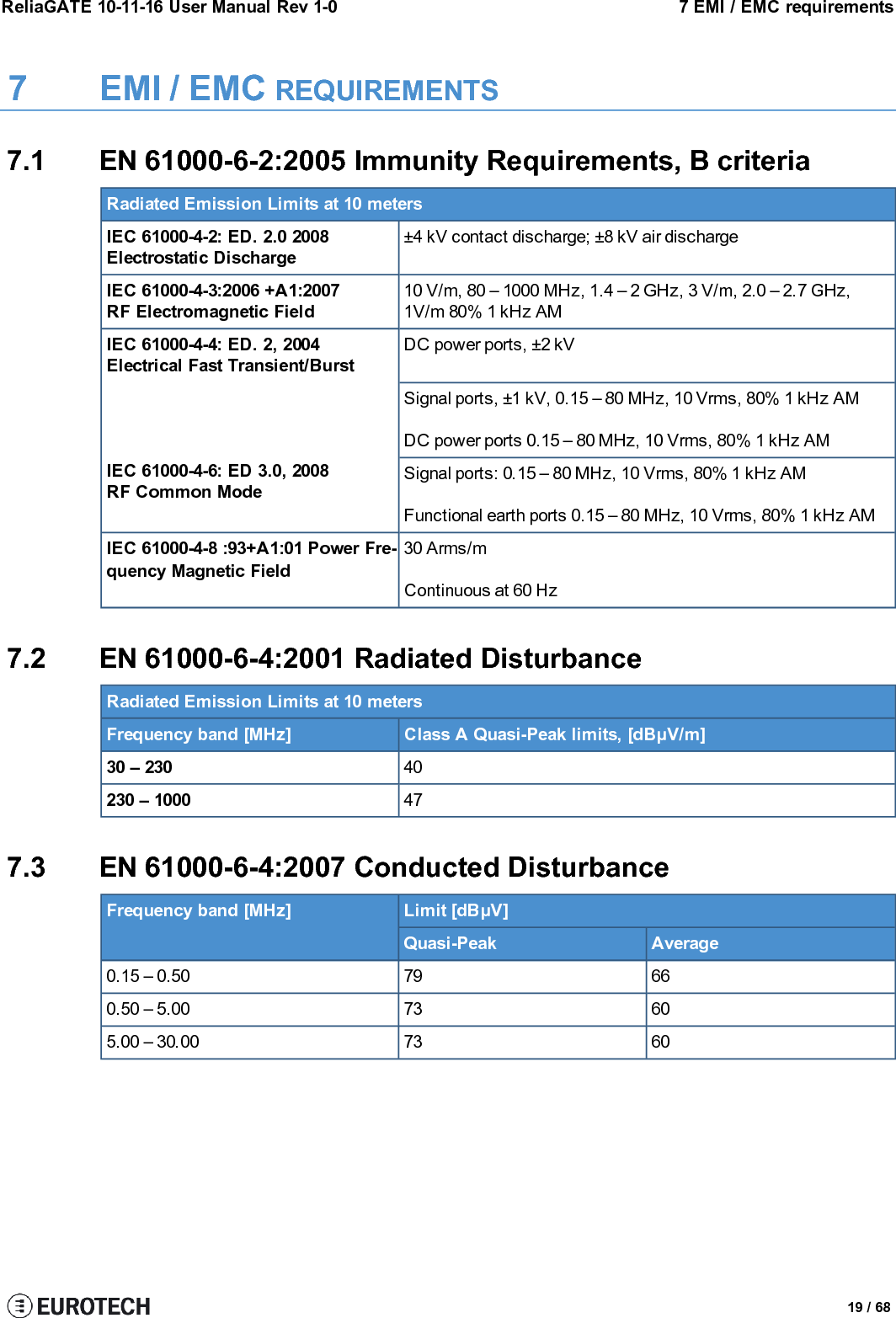
![14 How to access to Linux peripherals ReliaGATE 10-11-16 User Manual Rev 1-0Definition of the flags bit/*FLAGS *///#define SER_RS485_ENABLED (1 << 0)/* Logical level for RTS pin when sending *///#define SER_RS485_RTS_ON_SEND (1 << 1)/* Logical level for RTS pin after sent*///#define SER_RS485_RTS_AFTER_SEND (1 << 2)//#define SER_RS485_RX_DURING_TX (1 << 4)/* Inverted logic level for RS485 gpio */#define SER_RS485_INVERT (1 << 5)/* if enabled serial line drivers must be configured in HiZ*/#define SER_HIZ_ENABLED (1 << 31)Linux kernel data structurestruct serial_rs485 {__u32 flags; /* RS485 feature flags */__u32 delay_rts_before_send; /* Delay before send (milliseconds) */__u32 delay_rts_after_send; /* Delay after send (milliseconds) */__u32 padding[5]; /* Memory is cheap, new structs};Example: Configure the serial port in RS232 modeUse the example below to configure the serial port in RS232 mode.ser_port_name can be either /dev/ttyO3 or /dev/ttyO4.struct serial_rs485 rs485conf;unsigned int rs_mode_mask=(SER_HIZ_ENABLED|SER_RS485_ENABLED|SER_RS485_INVERT|SER_RS485_RTS_ON_SEND|SER_RS485_RTS_AFTER_SEND);unsigned int set_flags=0;unsigned int set_flags_mask=rs_mode_mask;int fd;fd=open(ser_port_name,O_RDWR);if (fd==-1){/* process the error */…}/* get serial port configuration */if (ioctl (fd, TIOCGRS485, & rs485conf) < 0){/* process the error */…}rs485conf.flags&=~ set_flags_mask;set_flags&=set_flags_mask;rs485conf.flags|= set_flags;54 / 68](https://usermanual.wiki/EUROTECH/MRG1011/User-Guide-2939376-Page-54.png)