User Manual

Original User Manual
ReliaGATE 10-11-16
Multi-Service Gateway & Edge Controller
Rev. 1-0 — 15 February 2016 — REGATE-10-11-16_UserMan_EN_1-0 — ENGLISH

Trademarks
All trademarks and registered trademarks are the property of their respective owners.
Revision history
Revision Description Date
1-0 First release 15 February 2016
© 2016 Eurotech SpA - Via Fratelli Solari 3/A - 33020 AMARO (UD) - Italy

ReliaGATE 10-11-16 User Manual Rev 1-0 Table of contents
TABLE OF CONTENTS
Trademarks 2
Revision history 2
Table of contents 3
1 Important Information 7
1.1 Signals used in this document 7
1.2 Disclaimer of liability 8
1.3 Intended audience 8
2 Safety Instructions 9
2.1 Observe antistatic precautions 9
2.2 Connect power supply correctly 9
3 How to receive technical assistance 11
3.1 How to receive technical support 11
3.2 How to return a product to Eurotech 11
4 Conventions used in this document 13
4.1 Conventions for signal names 13
4.2 Abbreviations for direction and electrical characteristics of a signal 13
5 Product overview 15
5.1 Product labels 16
6 Declaration of Conformity 17
6.1 FCC compliance 17
6.2 RoHS compliance 17
6.3 WEEE compliance 17
7 EMI / EMC requirements 19
7.1 EN 61000-6-2:2005 Immunity Requirements, B criteria 19
7.2 EN 61000-6-4:2001 Radiated Disturbance 19
7.3 EN 61000-6-4:2007 Conducted Disturbance 19
8 Technical Specifications 21
8.1 Notes about the power supply unit 22
9 Getting started 23
10 Product interfaces 25
10.1 Front panel interfaces 25
10.2 Rear panel interfaces 26
10.3 Service panel interfaces 27
10.4 LED indicators 28
10.5 Client USB interface 29
10.5.1 Connector and mating connector specifications 29
10.5.2 Connector pinout 29
11 Interfaces in detail 31
11.1 Digital I/O interfaces 31
11.1.1 Connector and mating connector specifications 31
11.1.2 Connector pinout 31
11.2 Serial ports 1 and 2 32
11.2.1 Connector and mating connector specifications 32
3 / 68

Table of contents ReliaGATE 10-11-16 User Manual Rev 1-0
11.2.2 Connector pinout 32
11.2.3 DIP switch for RS485 fail-safe resistors insertion 33
11.2.3.1 Switches meaning 33
11.3 CAN ports 0 and 1 34
11.3.1 Connector and mating connector specifications 34
11.3.2 Connector pinout 34
11.4 Cellular with integrated GPS 35
11.4.1 Cellular antenna specifications 35
11.4.2 Cellular modem specifications 35
11.4.3 GPS antenna specifications 36
11.4.4 GPS receiver specifications 36
11.5 Wi-Fi and Bluetooth 37
11.5.1 Antenna specifications 37
11.5.2 Wi-Fi specifications 37
11.5.3 Bluetooth specifications 37
11.5.4 BLE specifications 37
11.5.5 ANT specifications 38
11.6 Ethernet port 39
11.6.1 Connector and mating connector specifications 39
11.6.2 Connector pinout 39
11.6.3 Port specifications 39
11.7 Host USB ports 40
11.7.1 Connector and mating connector specifications 40
11.7.2 Connector pinout 40
11.8 Power features 41
11.8.1 Power supply 41
11.8.1.1 Connector and mating connector specifications 41
11.8.1.2 Connector pinout 41
11.8.2 Power Management 41
11.9 The Reset pushbutton 42
11.10 RTC (Real Time Clock) 43
11.10.1 The RTC device "/dev/rtc1" 43
11.10.2 The RTC battery 43
11.10.2.1 How to enable / disable the RTC battery 43
11.11 The Programmable pushbutton 44
11.12 The MicroSD card receptacle 45
11.13 The MicroSIM card receptacle 45
11.14 Debug Serial port 46
11.14.1 Connector and mating connector specifications 46
11.14.2 Connector pinout 46
11.15 Watchdog 47
12 Software 49
12.1 The Linux OS distribution 49
12.2 The bootloader procedure 49
12.2.1 How to select the MLO source 49
12.2.2 How to set up a correct microSD card / eMMC card partition 49
13 Administrative console 51
13.1 How to log in using the Serial console 51
13.2 How to log in using the Remote login 51
13.2.1 If your development PC is running Linux 51
13.2.2 If your development PC is running Windows 52
13.3 How to change your security settings 52
14 How to access to Linux peripherals 53
14.1 Ethernet port 53
4 / 68

ReliaGATE 10-11-16 User Manual Rev 1-0 Table of contents
14.2 Wi-Fi 53
14.3 Serial Ports 53
14.3.1 How to set the RS232/485 serial modes 53
14.3.1.1 Use the ethsetserial utility to configure the serial ports 53
14.3.1.2 Implement the ioctl in the source code to configure the serial ports 53
14.4 Modem 56
14.5 CAN Bus 56
14.5.1 How to enable the CAN bus 5V 56
14.6 Digital I/Os 57
14.7 LED indicators 57
14.7.1 How to drive a LED 57
14.8 Flash Memory 57
14.9 Watchdog 58
14.9.1 Manage the watchdog using the C programming language 58
14.9.2 Manage the watchdog from the command line 58
14.9.3 For furhter information 59
14.10 RTC 59
14.10.1 How to use the timestamp registers 59
14.10.2 How to use the user-available byte 60
14.10.3 How to automaticallly wake the ReliaGATE 10-11-16 up from the sleep mode 60
14.11 EEPROM 60
14.11.1 How to enable / disable the EEPROM write-protection 60
15 Mechanical specifications 63
16 Install / remove the product 65
16.1 Install the ReliaGATE 10-11-16 on a DIN rail 65
16.2 Remove the ReliaGATE 10-11-16 from a DIN rail 65
16.3 Remove the DIN mounting kit from the ReliaGATE 10-11-16 66
16.4 Install the DIN mounting kit on the ReliaGATE 10-11-16 66
Notes 67
5 / 68
(This page has been intentionally left blank)
ReliaGATE 10-11-16 User Manual Rev 1-0 1 Important Information
1 IMPORTANT INFORMATION
CAREFULLY READ AND UNDERSTAND THE INSTRUCTIONS CONTAINED IN THIS
DOCUMENT BEFORE INSTALLING / OPERATING THE PRODUCT.
KEEP THIS DOCUMENT FOR FUTURE REFERENCE.
Whenever you have any doubt regarding the correct understanding of the instructions contained in this
document contact your local Eurotech Technical Support Team (see the last page of this document for
further details).
To lower the risk of personal injury, electric shock, fire or damage to equipment, observe the following
precautions, as well as using good technical judgment, whenever installing / operating the product.
1.1 Signals used in this document
DANGER
INDICATES A HAZARD WITH A HIGH LEVEL OF RISK WHICH, IF NOT AVOIDED, WILL
RESULT IN DEATH OR SERIOUS INJURY
WARNING
INDICATES A HAZARD WITH A MEDIUM LEVEL OF RISK WHICH, IF NOT AVOIDED, COULD
RESULT IN DEATH OR SERIOUS INJURY
CAUTION
INDICATES A HAZARD WITH A LOW LEVEL OF RISK WHICH, IF NOT AVOIDED, COULD
RESULT IN MINOR OR MODERATE INJURY
NOTICE
Indicates practices not related to personal injury, such as:
lAn instruction to follow to use the product effectively
lA statement of company policy related to product or property protection
7 / 68

1 Important Information ReliaGATE 10-11-16 User Manual Rev 1-0
1.2 Disclaimer of liability
Eurotech has reviewed the contents of this document to ensure accuracy and consistency with the
hardware and software described.
Always refer to the latest available manual revision available at: www.eurotech.com.
1.3 Intended audience
This document is intended for system integrators, who are skilled persons with a thorough knowledge in
bringing together component subsystems into a whole, ensuring that those subsystems function together.
8 / 68
ReliaGATE 10-11-16 User Manual Rev 1-0 2 Safety Instructions
2 SAFETY INSTRUCTIONS
Observe the following safety instructions when installing / operating the product.
Failure to comply with these instructions or with specific warnings elsewhere in this document violates
safety standards of design, manufacture, and intended use of the product.
Eurotech assumes no liability for any failure to comply with these instructions.
2.1 Observe antistatic precautions
NOTICE
PREVENTING ELECTROSTATIC DISCHARGE (ESD)
When handing the product described in this document, always use appropriate
antistatic precautions to avoid damages due to electrostatic discharge.
For example: use a wrist strap or ESD cuff kept in constant contact with bare skin
and attached to an ESD ground.
2.2 Connect power supply correctly
WARNING
ELECTRIC SHOCK HAZARD
Before applying power, thoroughly review all installation, operation, and safety instructions.
Failure supply power correctly or to follow all operating instructions correctly, may create an
electric shock hazard, which could result in personal injury or loss of life, and / or damage to
equipment or other property.
To avoid injuries:
lBefore operating any equipment, carefully read any supplied instructions
lDo not perform any connections with wet hands
lCheck any power cords for damage before using them
lUse certified power cables. The power cables must meet the power requirements of the
device
lPosition cables with care. Avoid positioning cables in places where they may be
trampled or compressed by objects placed on them
lTake particular care of plugs, power-points and outlets. Avoid overcharging them
lAlways disconnect power and discharge the circuits before touching them
lOnly start the product with a power supply that meets the requirements stated on the
voltage label. In case of uncertainties about the required power supply, contact the
Eurotech Technical Support Team (see the back cover for full contact details) or the
electricity authority.
9 / 68
(This page has been intentionally left blank)

ReliaGATE 10-11-16 User Manual Rev 1-0 3 How to receive technical assistance
3 HOW TO RECEIVE TECHNICAL ASSISTANCE
3.1 How to receive technical support
If you have technical questions, or if you cannot isolate a problem with your product, or for any inquiry
about repair and returns policies, contact:
lThe Eurotech Global Support Center: https://eurotech.desk.com/
lYour local Eurotech Technical Support Team: see the back cover for full contact details.
3.2 How to return a product to Eurotech
To return a product to Eurotech, complete the following steps:
1. Send an email to the Eurotech RMA Department (rma.it@eurotech.com) specifying:
lProduct Model Number (printed on the product label)
lProduct Serial Number (printed on the product label)
lRecap of the fault description
2. Receive a reply from the Eurotech RMA Department. It contains:
lThe RMA number
lThe shipping information
3. Pack the product using anti-static material and place it in a sturdy box with enough packing material
to adequately cushion it
4. Ship the product to Eurotech following the information received from the Eurotech RMA
Department.
NOTICE
Any product returned to Eurotech that is found to be damaged due to inappropriate packaging
will not be covered by the warranty!
When shipping the product:
1. Pack it using anti-static material
2. Place it in a sturdy box with enough packing material to adequately cushion it.
11 / 68
(This page has been intentionally left blank)
ReliaGATE 10-11-16 User Manual Rev 1-0 4 Conventions used in this document
4 CONVENTIONS USED IN THIS DOCUMENT
4.1 Conventions for signal names
Convention Description
GND Digital ground plane
#Active low signal
_P Positive signal in differential pair
_N Negative signal in differential pair
4.2 Abbreviations for direction and electrical characteristics of
a signal
Convention Description
ISignal is an input to the system
OSignal is an output from the system
IO Signal may be input or output
PPower and ground
AAnalog signal
3.3 3.3 V signal level
55 V signal level
NC No Connection
Reserved Use is reserved to Eurotech
13 / 68
(This page has been intentionally left blank)
ReliaGATE 10-11-16 User Manual Rev 1-0 5 Product overview
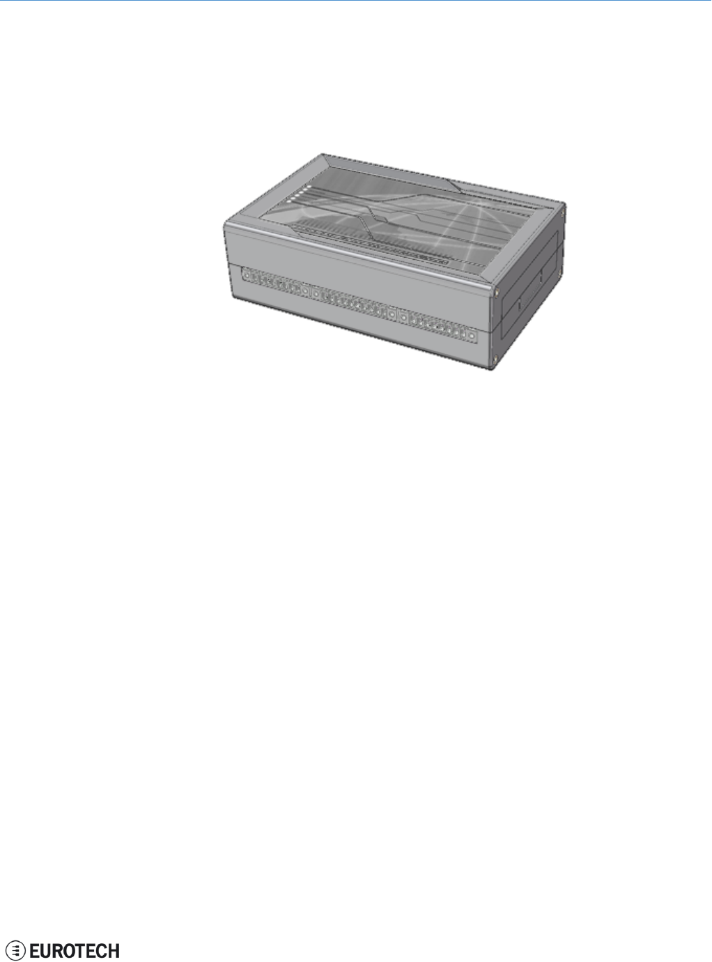
5 PRODUCT OVERVIEW
Your ReliaGATE 10-11-16 is a compact and lightweight IoT gateway based on the TI AM335X Cortex-A8
(Sitara) processor family, with 512MB of RAM, 4GB of eMMC, and a user-accessible microSD slot.
It is suitable for intensive workload in industrial and automotive applications. It supports a 9 to 36 V power
supply with transient protection and vehicle ignition sense, and features a wide range of connectivity
capabilities.
Figure 5.1 - The ReliaGATE 10-11-16
15 / 68
5 Product overview ReliaGATE 10-11-16 User Manual Rev 1-0
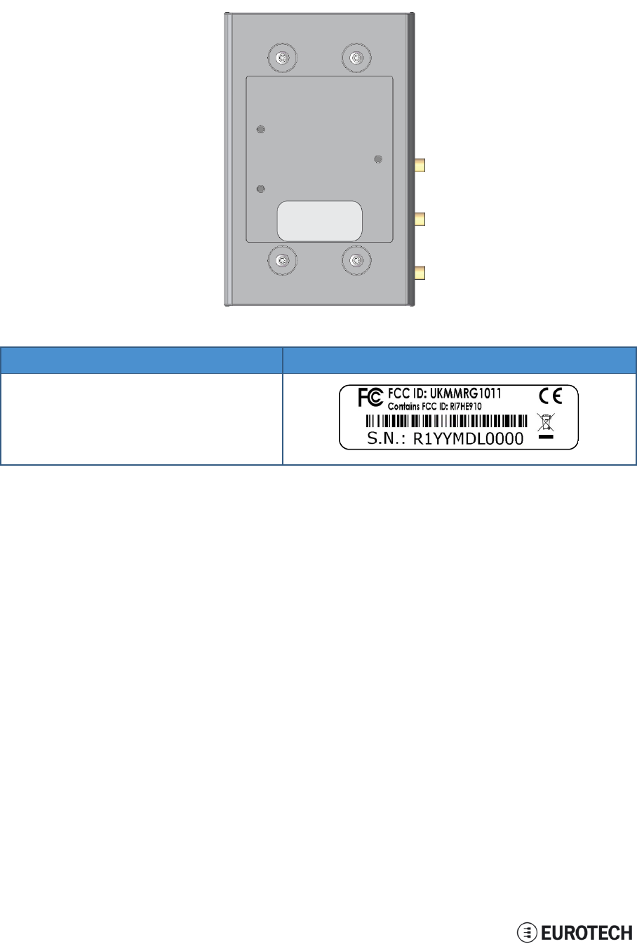
5.1 Product labels
The product label is placed on the bottom side of the product.
Label content Label example
• FCC ID numbers
• ReliaGATE serial number in bar-code format
• ReliaGATE serial number in figures
• CE mark
• WEEE symbol
16 / 68
ReliaGATE 10-11-16 User Manual Rev 1-0 6 Declaration of Conformity
6 DECLARATION OF CONFORMITY
The ReliaGATE 10-11-16 conforms to the following:
lReduction of Certain Hazardous Substances (RoHS2)
lCE Mark
lWi-Fi and Bluetooth Radio:
oCE - EN300 328 (2.4GHz ISM), EN50371 (EMI), EN301 489 (EMC)
oFCC - 15.209 (General RF device), 15.247 & 15.249 (2.4GHz ISM)
lCellular Radio:
oFCC PART 22, 24 & 27 and suitable GSM radio certifications
lUL 60950-1 Information Technology Equipment - Safety - Part 1: General Requirements
lProduct compliance with part 15.21 of FCC
6.1 FCC compliance
This device and its accessories comply with part 15 of FCC rules. Operation is subject to the following two
conditions:
1. This device and its accessories may not cause harmful interference.
2. This device and its accessories must accept any interference received, including interference that
may cause undesired operation.
Change or modifications that are not expressly approved by the manufacturer could void the user's
authority to operate the equipment.
FCC ID: UKMMRG1011
Contains FCC ID: RI7HE910
6.2 RoHS compliance
The product described in this document, including all its components and its sub-assemblies, have been
manufactured in compliance with the Directive 2011/65/EU of the European Parliament and of the Council
of 8 June 2011 on the restriction of the use of certain hazardous substances in electrical and electronic
equipment.
6.3 WEEE compliance
In compliance with the Directive 2012/19/EU of the European Parliament and of the Council
of 4 July 2012 on waste electrical and electronic equipment (WEEE), the symbol on the
right, shown on the product or within its literature, indicates separate collection for this
electrical and electronic equipment (EEE) that has been placed on the market after 2005.
This product, at the end of its life cycle, must be collected separately and managed in
accordance with the provisions of the current Directive on waste electrical and electronic
equipment.
Because of the substances present in the product, improper use or disposal of the refuse
can cause damage to human health and the environment.
To avoid any possible legal implications, contact your local waste collection body for full
recycling information.
17 / 68
(This page has been intentionally left blank)
ReliaGATE 10-11-16 User Manual Rev 1-0 7 EMI / EMC requirements
7 EMI / EMC REQUIREMENTS
7.1 EN 61000-6-2:2005 Immunity Requirements, B criteria
Radiated Emission Limits at 10 meters
IEC 61000-4-2: ED. 2.0 2008
Electrostatic Discharge
±4 kV contact discharge; ±8 kV air discharge
IEC 61000-4-3:2006 +A1:2007
RF Electromagnetic Field
10 V/m, 80 – 1000 MHz, 1.4 – 2 GHz, 3 V/m, 2.0 – 2.7 GHz,
1V/m 80% 1 kHz AM
IEC 61000-4-4: ED. 2, 2004
Electrical Fast Transient/Burst
IEC 61000-4-6: ED 3.0, 2008
RF Common Mode
DC power ports, ±2 kV
Signal ports, ±1 kV, 0.15 – 80 MHz, 10 Vrms, 80% 1 kHz AM
DC power ports 0.15 – 80 MHz, 10 Vrms, 80% 1 kHz AM
Signal ports: 0.15 – 80 MHz, 10 Vrms, 80% 1 kHz AM
Functional earth ports 0.15 – 80 MHz, 10 Vrms, 80% 1 kHz AM
IEC 61000-4-8 :93+A1:01 Power Fre-
quency Magnetic Field
30 Arms/m
Continuous at 60 Hz
7.2 EN 61000-6-4:2001 Radiated Disturbance
Radiated Emission Limits at 10 meters
Frequency band [MHz] Class A Quasi-Peak limits, [dBμV/m]
30 – 230 40
230 – 1000 47
7.3 EN 61000-6-4:2007 Conducted Disturbance
Frequency band [MHz] Limit [dBμV]
Quasi-Peak Average
0.15 – 0.50 79 66
0.50 – 5.00 73 60
5.00 – 30.00 73 60
19 / 68
(This page has been intentionally left blank)

ReliaGATE 10-11-16 User Manual Rev 1-0 8 Technical Specifications
8 TECHNICAL SPECIFICATIONS
Specifications Description
Processor CPU TI AM335X, 800 MHz, 1 core
Memory RAM 512 MB, DDR3
Storage Embedded 4 GB eMMC
Other MicroSD slot (user accessible)
I/O interfaces
Ethernet 1x Fast Ethernet port
USB 2x USB 2.0 host port
1x USB 2.0 client port
Serial 2x RS232/485 (Surge protected, RS485 fail-safe resistors user accessible)
1x TTL Serial console
CAN 2x CAN 2.0B ports
Digital I/O 2x Insulated Digital Input
2x Insulated Digital Output
Radio interfaces
Cellular Integrated 3G, global, with GPS
Micro SIM card slot available behind the Service panel
GPS Integrated in Cellular
Wi-Fi / BT 802.11b,g,n / 4.0 BLE
Antennas (external)
1x SMA Cellular
1x SMA GPS
1x RP-SMA Wi-Fi / Bluetooth
Other
RTC Yes (user accessible battery)
Ext. watchdog Yes
EEPROM on I2C 256 kb
Sensors Not present
LEDs
1x Power
1x Cellular activity
4x User configurable
Buttons 1x Reset, 1x Programmable
SIM slot 1x microSIM (user accessible)
Power Input Nominal: 24 V dc; Range: 9 - 36 V dc with transient protection, vehicle ignition sense
Consumption 2W idle
Environment Operating Temp -20 °C to +70 °C
Storage Temp -40 °C to +80 °C
Certifications
Regulatory CE, FCC, E-mark
Safety IC 60950-U
Environmental RoHS2; REACH
Radio FCC, PTCRB
Cellular FCC, PTCRB
Ingress IP40
MTBF >40000 h or 5 years
Mechanical
Enclosure Material: ABS - Color: aluminum
Dimensions 139 (L) x 95 (W) x 48 (H); mm
Weight 160 g
Mounting Removable DIN mounting kit
21 / 68

8 Technical Specifications ReliaGATE 10-11-16 User Manual Rev 1-0
8.1 Notes about the power supply unit
The ReliaGATE 10-11-16 comes equipped with a FRIWO MPP 15, 15 W switch-mode power supply unit.
The power supply unit has the following features:
lModel number: FRIWO MPP 15 (FW 7520/24)
lInput voltage: 100 to 240 V ac
lOutput voltage: 24 V dc
lOutput current: 625 mA
lPower rating: 15 W
lType: Switch mode
22 / 68

ReliaGATE 10-11-16 User Manual Rev 1-0 9 Getting started
9 GETTING STARTED
Follow these steps to get started with the ReliaGATE 10-11-16:
1. Know the ReliaGATE 10-11-16 interfaces.
The ReliaGATE 10-11-16 provides connectivity to several wired and wireless interfaces.
For further information, see:
l"Product interfaces" on page 25
l"Interfaces in detail" on page 31
2. Apply power to the ReliaGATE 10-11-16.
The ReliaGATE 10-11-16 supports a variety of usage scenarios.
For further information, see "Power features" on page 41
3. Log into the administrative console.
The ReliaGATE 10-11-16 runs a Linux distribution based on a Yocto framework and supports login
via a variety of methods.
For further information, see:
l"Software" on page 49
l"Administrative console" on page 51
l"How to access to Linux peripherals" on page 53
4. Install the ReliaGATE 10-11-16.
The ReliaGATE 10-11-16 is lightweight and compact. You can easily install it on a DIN rail.
For further information, see:
l"Mechanical specifications" on page 63
l"Install / remove the product" on page 65
23 / 68
(This page has been intentionally left blank)
ReliaGATE 10-11-16 User Manual Rev 1-0 10 Product interfaces
10 PRODUCT INTERFACES
This section gives you an overview of the interfaces on the ReliaGATE 10-11-16.
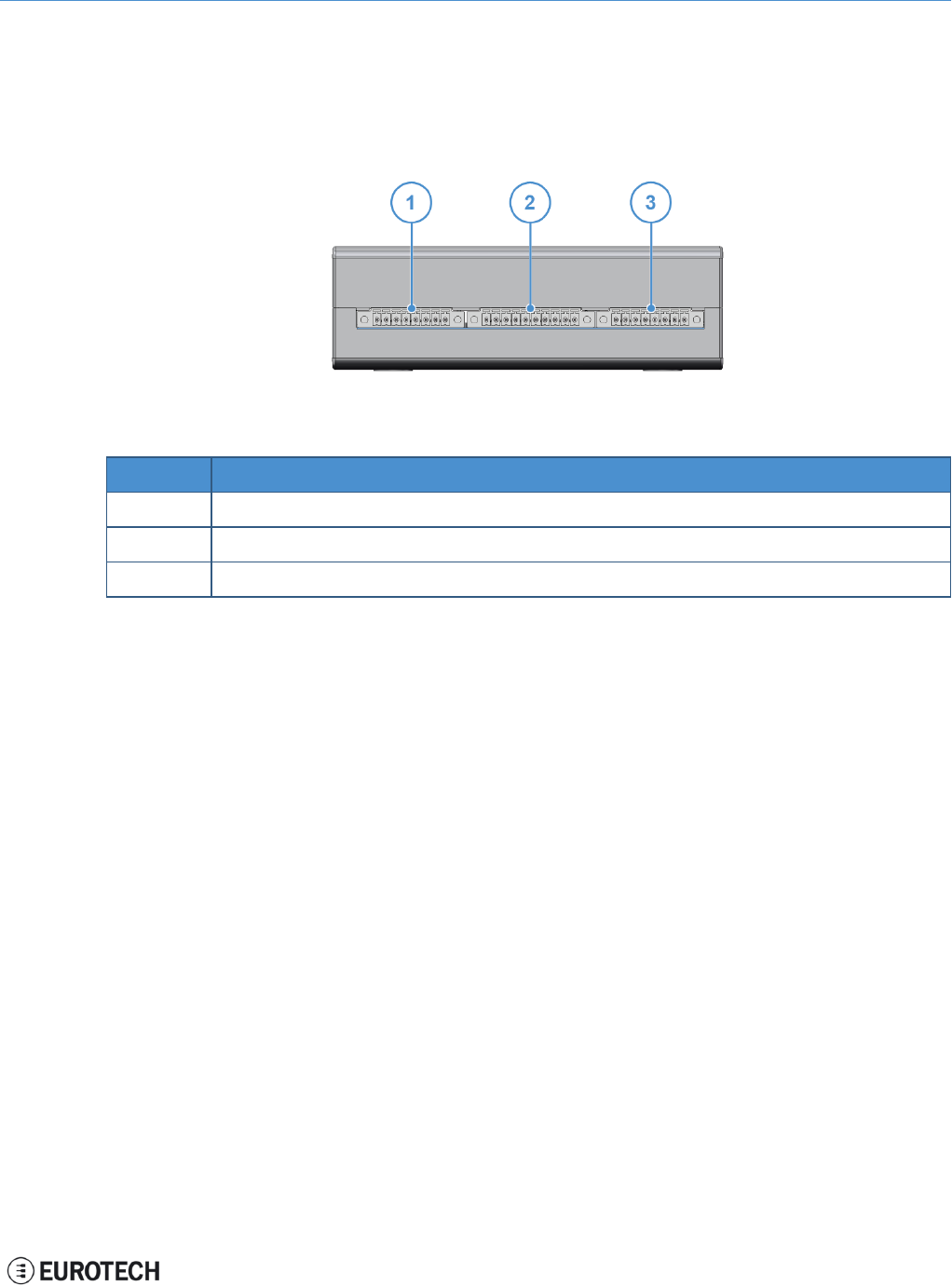
10.1 Front panel interfaces
The interfaces available on the front panel are the following:
Figure 10.1 - Front panel interfaces layout
Ref# Description
1Digital I/Os
2Serial ports 1 and 2
3CAN ports
Table 10.1 - Rear panel interfaces description
25 / 68
10 Product interfaces ReliaGATE 10-11-16 User Manual Rev 1-0
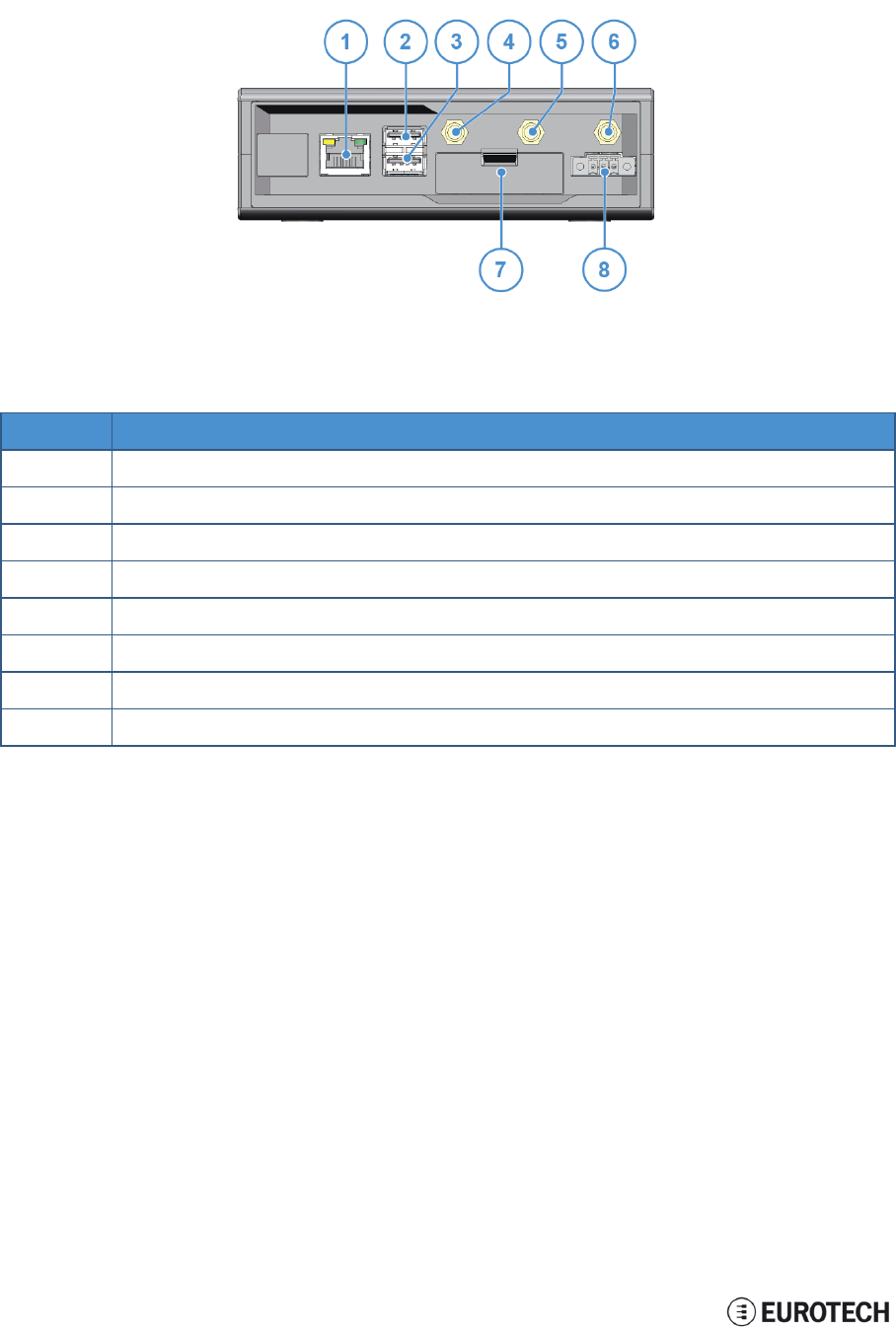
10.2 Rear panel interfaces
The interfaces available on the rear panel are the following:
Figure 10.2 - Rear panel interfaces layout
Ref# Description
1Ethernet 0 port
2USB 0 host port
3USB 1 host port
4Cellular antenna
5GPS antenna
6Wi-Fi/BT antenna
7Service Panel
8Power supply input
Table 10.2 - Rear panel interfaces description
26 / 68
ReliaGATE 10-11-16 User Manual Rev 1-0 10 Product interfaces
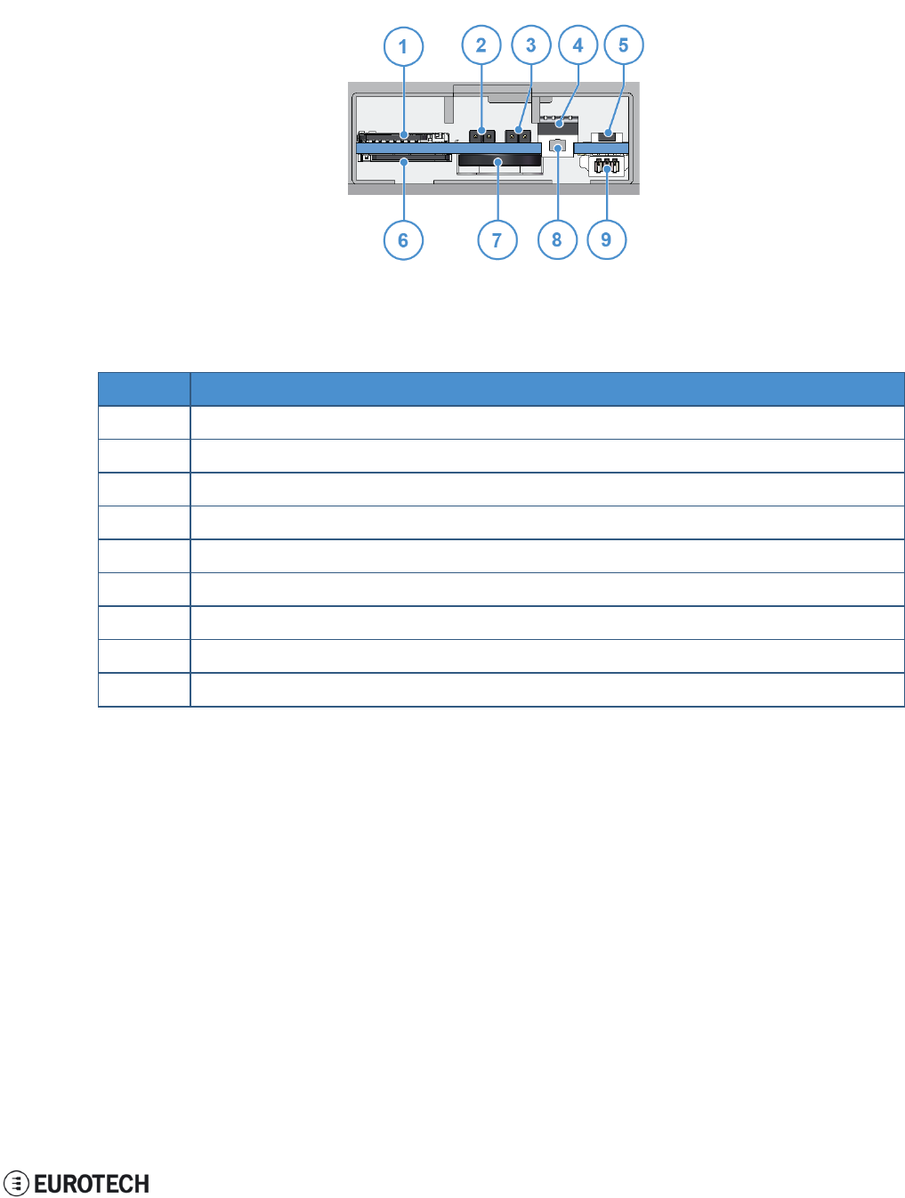
10.3 Service panel interfaces
The interfaces available behind the service panel are the following:
Figure 10.3 - Service panel interfaces layout
Ref# Description
1Micro SD card
2RTC battery connection jumper
3Boot selection jumper
4Serial port configuration DIP-switch
5Programmable pushbutton
6Micro SIM card
7RTC battery
8Reset pushbutton
9Debug Serial port
Table 10.3 - Service panel interfaces description
27 / 68
10 Product interfaces ReliaGATE 10-11-16 User Manual Rev 1-0
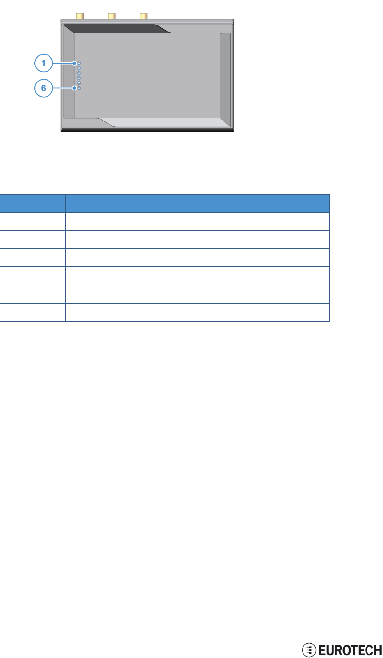
10.4 LED indicators
The LED indicators are available on the top side of the ReliaGATE 10-11-16:
Figure 10.4 - LED indicators layout
Ref# Use Color
1USER1 (General purpose) Green
2USER2 (General purpose) Green
3USER3 (General purpose) Red
4USER4 (General purpose) Red
5CELL (Modem activity) Red
6POWER Green
Table 10.4 - LED indicators description
28 / 68
ReliaGATE 10-11-16 User Manual Rev 1-0 10 Product interfaces
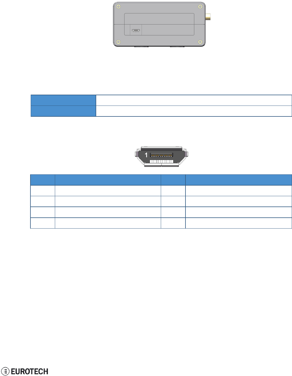
10.5 Client USB interface
A USB 2.0 client interface for add-on modules is available on the right side.
This interface is noise and surge protected.
Figure 10.5 - Client USB interface layout
10.5.1 Connector and mating connector specifications
Connector Micro-B USB socket
Mating connector Micro-B USB plug
10.5.2 Connector pinout
Pin# Name Type Description
1VBUS 5 +5V
2D- IO Negative data
3D+ IO Positive data
4DGND P Digital ground
29 / 68
(This page has been intentionally left blank)
ReliaGATE 10-11-16 User Manual Rev 1-0 11 Interfaces in detail
11 INTERFACES IN DETAIL
11.1 Digital I/O interfaces
The ReliaGATE 10-11-16 provides:
l2x Digital Inputs:
oIndependent 1 kV optoinsulated voltage (or volt free)
o5V TTL level
oNot protected against reverse voltage polarity
l2x Digital Outputs
oOpen collector (or drain)
o50 V DC rated with sink capacity of 10 mA
o1 kHz maximum switching frequency
These interfaces are available on the front panel
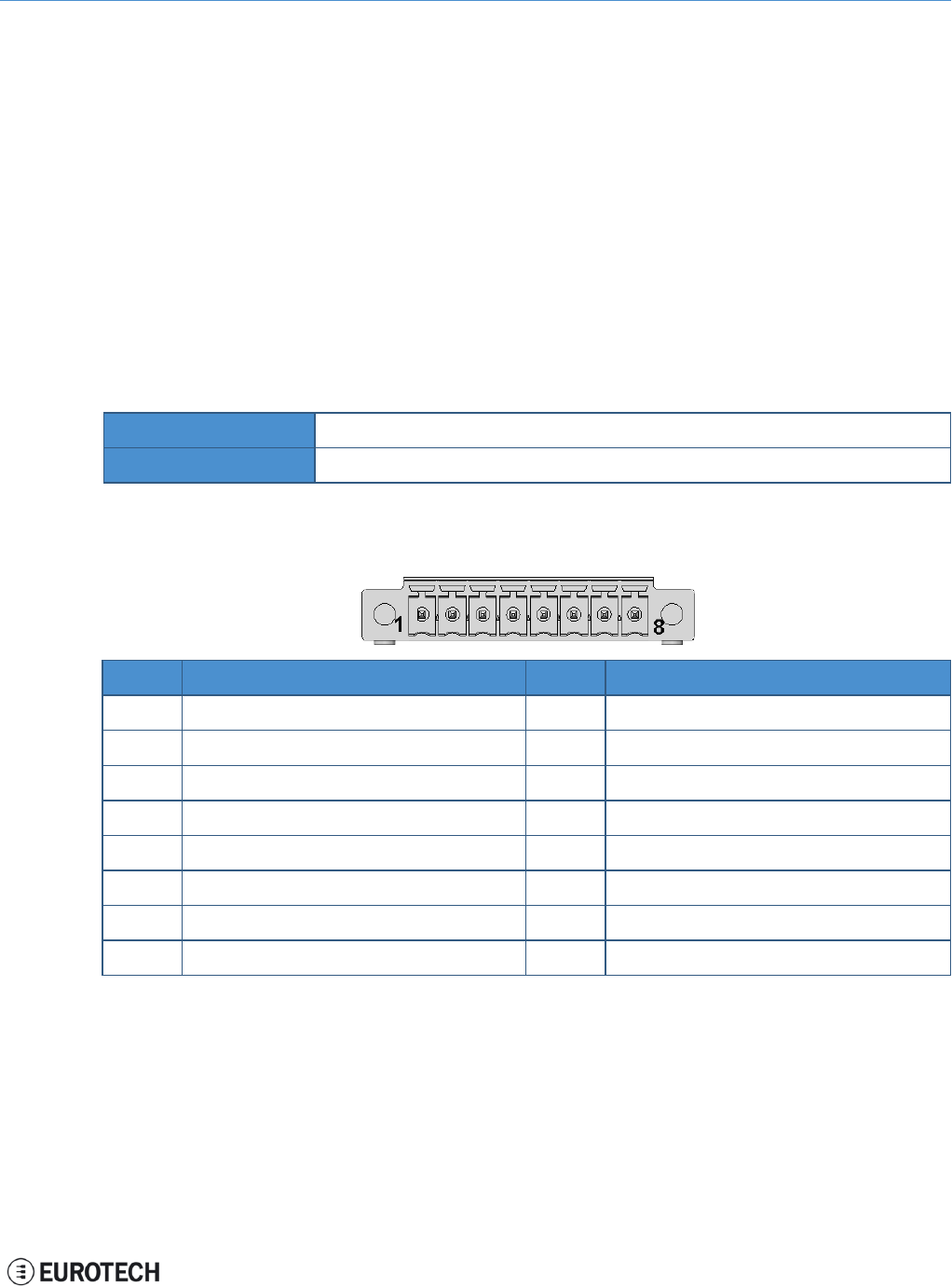
11.1.1 Connector and mating connector specifications
Connector Phoenix Contacts MC 1.5/ 8-GF-3.5
Mating connector
11.1.2 Connector pinout
Pin# Name Type Description
1Digital OUT: 1C O Digital Output 1 Collector
2Digital OUT: 1E O Digital Output 1 Emitter
3Digital OUT: 2C O Digital Output 2 Collector
4Digital OUT: 2E O Digital Output 2 Emitter
5Digital IN: 1A I Digital Input 1 Anode
6Digital IN: 1C I Digital Input 1 Cathode
7Digital IN: 2A I Digital Input 2 Anode
8Digital IN: 2C I Digital Input 2 Cathode
31 / 68
11 Interfaces in detail ReliaGATE 10-11-16 User Manual Rev 1-0
11.2 Serial ports 1 and 2
The ReliaGATE 10-11-16 provides 2 serial ports on the front panel. The interfaces are surge protected.
Maximum supported baud rates are:
lFor RS232 mode: up to 450 kbps
lFor RS485 mode: up to 3.6864 Mbps
Each data signal is routed to two different pins on the connector.
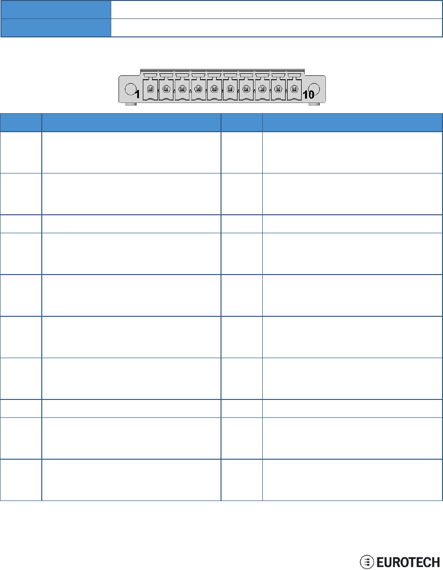
11.2.1 Connector and mating connector specifications
Connector Phoenix Contacts MC 1.5/ 10-GF-3.5
Mating connector -
11.2.2 Connector pinout
Pin# Name Type Description
1Serial 1: TX/B O Serial port 1:
lRS232: Transmit Data
lRS485: B Line
2Serial 1: RX/A I Serial port 1:
lRS232: Receive Data
lRS485: A Line
3Serial 1: DGND P Digital Ground
4Serial 1: RX/A I Serial port 1:
lRS232: Receive Data
lRS485: A Line
5Serial 1: TX/B O Serial port 1:
lRS232: Transmit Data
lRS485: B Line
6Serial 2: TX/B O Serial port 2:
lRS232: Transmit Data
lRS485: B Line
7Serial 2: RX/A I Serial port 2:
lRS232: Receive Data
lRS485: A Line
8Serial 2: DGND P Digital Ground
9Serial 2: RX/A I Serial port 2:
lRS232: Receive Data
lRS485: A Line
10 Serial 2: TX/B O Serial port 2:
lRS232: Transmit Data
lRS485: B Line
32 / 68
ReliaGATE 10-11-16 User Manual Rev 1-0 11 Interfaces in detail
Note for termination resistors and fail safe resistors in RS485 mode:
lTermination resistors: you can insert them using the additional pins
lFail safe resistors: you can insert them using the DIP switch located behind the Service Panel.
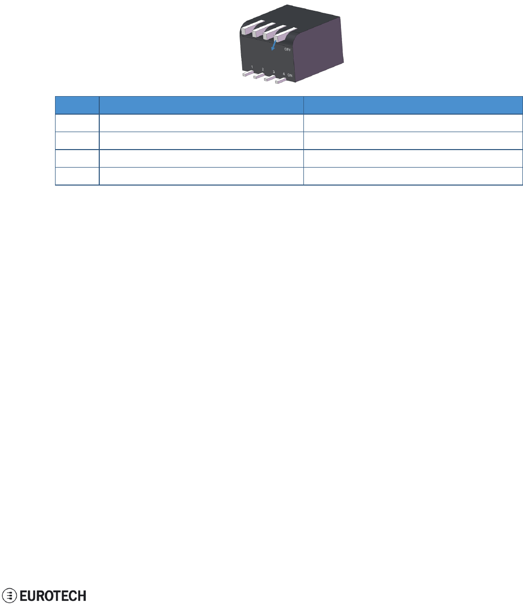
11.2.3 DIP switch for RS485 fail-safe resistors insertion
You can use this DIP switch to insert the RS485 fail-safe resistors.
11.2.3.1 Switches meaning
Default DIP switch configuration is OFF; this means no resistors inserted.
SW# Signal Description
1RS232RX_1 / RS485+_1 ON: 4.7 kΩ pull-up resistor inserted
2RS232TX_1 / RS485-_1 ON: 4.7 kΩ pull-down resistor inserted
3RS232RX_2 / RS485+_2 ON: 4.7 kΩ pull-up resistor inserted
4RS232TX_2 / RS485-_2 ON: 4.7 kΩ pull-down resistor inserted
33 / 68
11 Interfaces in detail ReliaGATE 10-11-16 User Manual Rev 1-0
11.3 CAN ports 0 and 1
The ReliaGATE 10-11-16 provides 2 CAN (Controller Area Network) ports compliant with the CAN
Specification 2.0, Parts A and B.
These interfaces are available on the front panel.
Notes about CANpower supply:
lThe ReliaGATE 10-11-16 can supply power to the 2 CAN ports: 100 mA @ 5V (each port)
lCAN power can be enabled / disabled by software
lThe interfaces are surge protected.
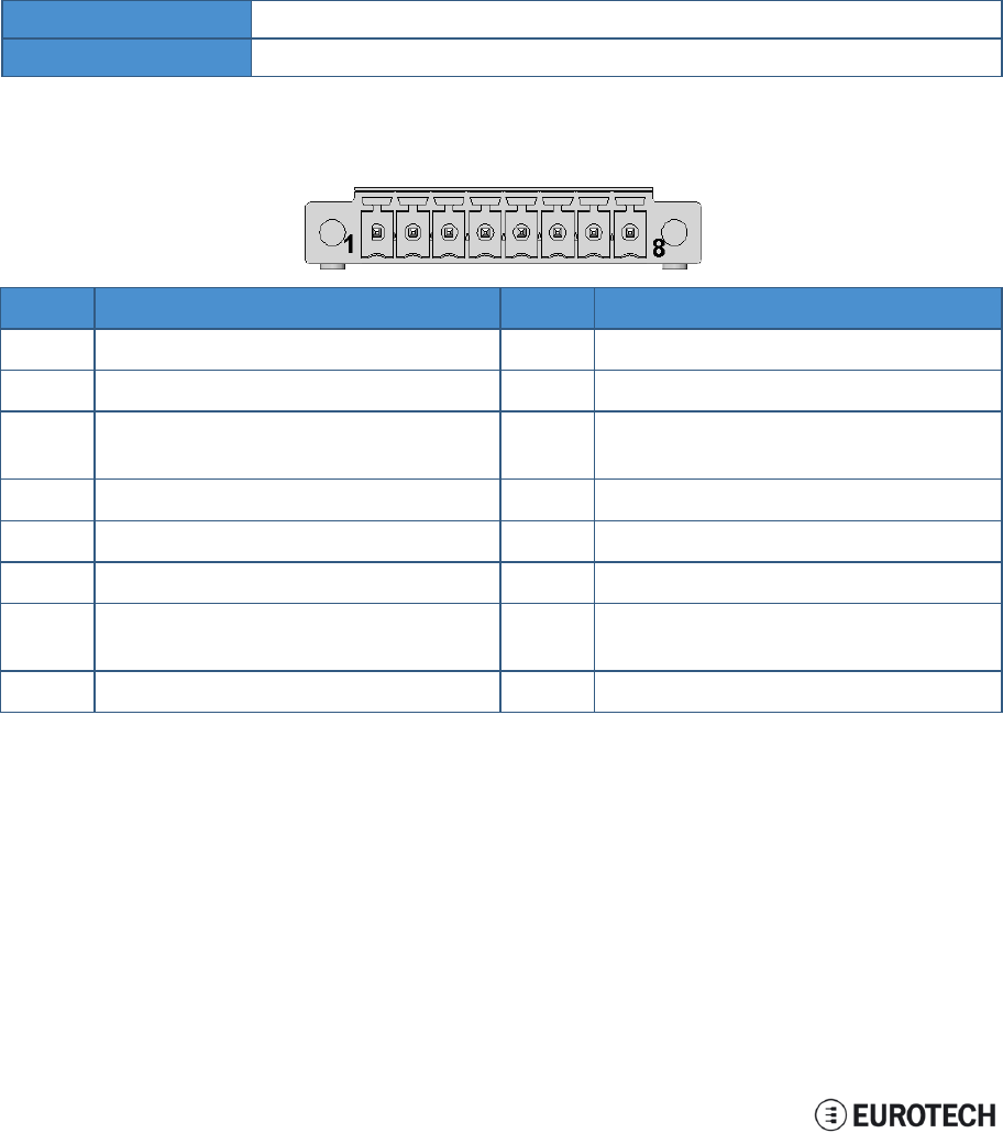
11.3.1 Connector and mating connector specifications
Connector Phoenix Contacts MC 1.5/ 1-GF-3.5
Mating connector -
11.3.2 Connector pinout
Pin# Name Type Description
1CAN 0: H IO CAN port 0 Positive Data
2CAN 0: L IO CAN port 0 Negative Data
3CAN 0: 5V 5 CAN node 0
5 V Output power supply
4CAN 0: DGND P Digital Ground
5CAN 1: H IO CAN port 1 Positive Data
6CAN 1: L IO CAN port 1 Negative Data
7CAN 1: 5V 5 CAN node 1
5 V Output power supply
8CAN 1: DGND P Digital Ground
34 / 68

ReliaGATE 10-11-16 User Manual Rev 1-0 11 Interfaces in detail
11.4 Cellular with integrated GPS
The ReliaGATE 10-11-16 provides a cellular modem with integrated GPS receiver on an external antennas
connection.
The cellular modem has the following approvals:
lFully type approved confirming with R&TTE directive
lCE, GCF (Global and Europe / Australia / New Zealand / Brazil variants)
lFCC, IC, PTCRB (North America variants)
11.4.1 Cellular antenna specifications
Cellular is available using an external cellular antenna.
Connector Female SMA
Mating connector Male SMA
11.4.2 Cellular modem specifications
lAdvanced E-GPRS/WCDMA/HSDPA/HSUPA Software protocol stack
l(Layer 1 to 3) – Version: 3GPP Release 7
lGSM Quad band (850, 900, 1800, 1900)
lWCDMA Multi-band (I, II, IV, V, VI, VIII and XIX)
lHSDPA up 21.0Mbps (for the high-end variants; up to 7.2 Mbps for the others)
lHSUPA up to 5.76Mbps
lWCDMA up to 384kbps downlink/uplink
lDTM (Dual Transfer Mode)
lReceive Diversity, type3i interference cancellation receiver
lCPC (DRX/DTX) (Continuous Packet Connectivity)
lDARP
lControl via AT commands according to 3GPP TS27.005, 27.007 and Telit customized AT
commands
lSerial port multiplexer 3GPP TS27.010
lSIM application Tool Kits 3GPP TS 51.014
lPower consumption (typical values):
oStand-by current 2G, DRX5, 1.1 mA
oStand-by current 3G, DRX7, 1.2 mA
lOutput power
oClass 4 (2W) @ 850 / 900 MHz, GSM
oClass 1 (1W) @ 1800 / 1900 MHz, GSM
oClass E2 (0.5W) @ 850/900 MHz, EDGE
oClass E2 (0.4W) @ 1800/1900 MHz, EDGE
oClass 3 (0.25W) @ 850/900/1700/1900/2100 MHz, WCDMA
lSensitivity:
o-109 dBm (typ.) @ 850 / 900 MHz (GSM)
o-110 dBm (typ.) @ 1800 / 1900 MHz (GSM)
o-111 dBm (typ.) @ 850/900/1700/1900 / 2100 MHz (WCDMA)
35 / 68

11 Interfaces in detail ReliaGATE 10-11-16 User Manual Rev 1-0
11.4.3 GPS antenna specifications
GPS is available using an external GPS antenna with a frequency of 1575.42 MHz (GPS L1).
Typically, GPS antennas must have line of sight to a wide area of the sky in order to receive signals from
multiple positioning satellites.
Connector Female SMA
Mating connector Male SMA
11.4.4 GPS receiver specifications
lAdvanced real time hardware correlation engine for enhanced sensitivity (better than -165 dBm for
A-GPS)
lFast Acquisition giving rapid Time-to-First-Fix (TTFF)
lCapability to monitor up to 28 channels
lStand Alone and Assisted mode (SUPL 1.0)
lIntegrated LNA
lAccuracy: 3 m
lHot start autonomous time: 1.8 s
lWarm start autonomous time: 30 s
lCold start autonomous time: 42 s
lL1 1575.42 MHz
lGPS NMEA 0183 output format
lDatum WGS-84
36 / 68

ReliaGATE 10-11-16 User Manual Rev 1-0 11 Interfaces in detail
11.5 Wi-Fi and Bluetooth
The ReliaGATE 10-11-16 includes a Wi-Fi & Bluetooth (BT) module and an external antenna connection to
fully implement Wi-Fi 802.11b/g/n and Bluetooth 4.0 BLE functions.
The circuitry allows for Wi-Fi and Bluetooth coexistence.
11.5.1 Antenna specifications
Connector Female RP-SMA
Mating connector Male RP-SMA
11.5.2 Wi-Fi specifications
lIntegrated 2.4 & 5G GHz Power Amplifier (PA) for WLAN solution
lWLAN Baseband Processor and RF transceiver Supporting IEEE Std 802.11b/g/n
lWLAN 2.4GHz SISO (20/40 MHz channels)
l2.4-GHz MRC Support for Extended Range
lBaseband Processor:
oIEEE Std 802.11a/b/g/n data rates and IEEE Std 802.11n data rates with 20 or 40 MHz
SISO.
lFully calibrated system. Production calibration not required.
lMedium Access Controller (MAC):
oEmbedded ARM™ Central Processing Unit (CPU)
oHardware-Based Encryption/Decryption using 64-, 128-, and 256-Bit WEP, TKIP or AES
Keys,
oSupports requirements for Wi-Fi Protected Access (WPA and WPA2.0) and IEEE Std
802.11i [includes hardware-accelerated Advanced Encryption Standard (AES)]
oDesigned to work with IEEE Std 802.1x
lIEEE Std 802.11d,e,h,i,k,r PICS compliant.
lNew advanced co-existence scheme with BT/BLE/ANT.
l2.4 GHz Radio:
oInternal LNA and PA
oSupports: IEEE Std 802.11a, 802.11b, 802.11g and 802.11n
lSupports 4 bit SDIO host interface, including high speed (HS) and V3 modes
11.5.3 Bluetooth specifications
lSupports Bluetooth 4.0 as well as CSA2
lIncludes concurrent operation and built -in coexisting and prioritization handling of Bluetooth, BLE,
ANT, audio processing and WLAN
lDedicated Audio processor supporting on chip SBC encoding + A2DP:
oAssisted A2DP (A3DP) support - SBC encoding implemented internally
oAssisted WB-Speech (AWBS) support - modified SBC codec implemented internally
11.5.4 BLE specifications
lFully compliant with BT4.0 BLE dual mode standard
lSupport for all roles and role-combinations, mandatory as well as optional
lSupports up to 10 BLE connections
lIndependent buffering for LE allows having large number of multiple connections without affecting
BR/EDR performance
37 / 68

11 Interfaces in detail ReliaGATE 10-11-16 User Manual Rev 1-0
11.5.5 ANT specifications
Fully compliant with all ANT Protocols:
lANT solution optimized for the fitness and health use-cases
lSimple to complex network topologies
lSupports high-resolution proximity pairing
38 / 68
ReliaGATE 10-11-16 User Manual Rev 1-0 11 Interfaces in detail
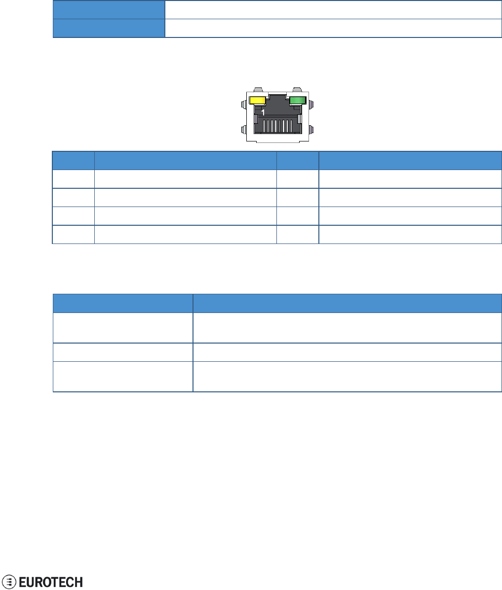
11.6 Ethernet port
Your ReliaGATE 10-11-16 provides one 10/100 Mbps Ethernet port for wired network connectivity.
This interface is available on the rear panel:
lit is referenced as eth0
11.6.1 Connector and mating connector specifications
Connector Female RJ-45
Mating connector Male RJ-45
11.6.2 Connector pinout
Pin# Name Type Description
1TX+ O Transmit Data +
2TX- O Transmit Data -
3RX+ I Receive Data +
6RX- I Receive Data -
11.6.3 Port specifications
Feature Description
Network Standard IEEE802.3u 10/100-BaseTX.
IEEE 802.3x full-duplex flow control.
Speeds 10/100-BaseTX interfaces with MAC
Notes The interfaces are noise and surge protected.
The RJ-45 connector has integrated magnetics.
39 / 68
11 Interfaces in detail ReliaGATE 10-11-16 User Manual Rev 1-0
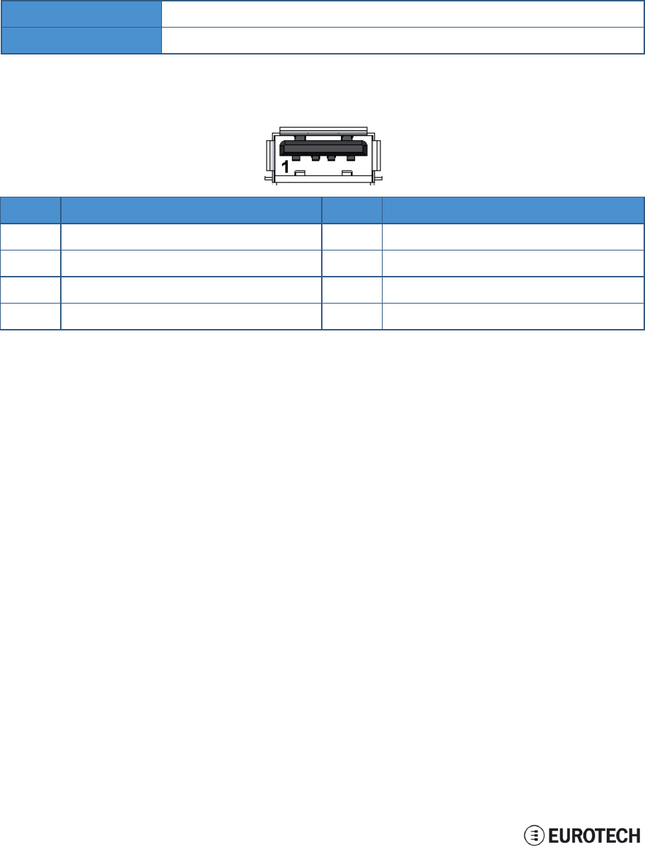
11.7 Host USB ports
The ReliaGATE 10-11-16 provides 2 USB 2.0 host ports for general purpose applications.
These interfaces are available on the rear panel, and are noise and surge protected.
11.7.1 Connector and mating connector specifications
Connector USB Type-A socket
Mating connector USB Type-A plug
11.7.2 Connector pinout
Pin# Name Type Description
1VBUS 5 +5V
2D- IO Negative data
3D+ IO Positive data
4DGND P Digital ground
40 / 68
ReliaGATE 10-11-16 User Manual Rev 1-0 11 Interfaces in detail
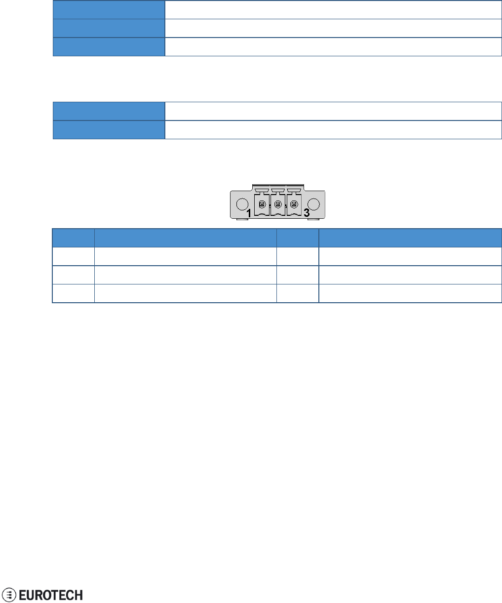
11.8 Power features
11.8.1 Power supply
The ReliaGATE 10-11-16 provides the power supply input port on the rear panel.
The port is protected against: surge, noise, reverse polarity, over-voltage and short circuit.
The power input is protected with a resettable fuse.
Power supply Nominal: 24 V dc; Range: 9 - 36 V dc with transient protection
Power consumption 2 W
Peak demand < 15 W
11.8.1.1 Connector and mating connector specifications
Connector Phoenix Contacts MC 1,5/ 3-GF-3,5
Mating connector -
11.8.1.2 Connector pinout
Pin# Name Type Description
1VIN+ P Positive power supply input
2VIN- P Negative power supply input
3DGND P Digital Ground
11.8.2 Power Management
You can reduce the power consumption of the ReliaGATE 10-11-16 by turning off the radio interfaces and /
or setting the CPU in low power consumption mode (stand-by / deep sleep).
The maximum power consumption at the lowest power state is ≤ 0.4 W.
The ReliaGATE 10-11-16 can be woken up from the low power consumption mode by:
lthe RTC alarm
41 / 68
11 Interfaces in detail ReliaGATE 10-11-16 User Manual Rev 1-0
11.9 The Reset pushbutton
A reset pushbutton is available to trigger a hardware reset of the ReliaGATE 10-11-16.
The pushbutton is located behind the Service Panel.
42 / 68
ReliaGATE 10-11-16 User Manual Rev 1-0 11 Interfaces in detail
11.10 RTC (Real Time Clock)
The ReliaGATE 10-11-16 includes the following two RTC (Real Time Clocks) devices:
RTC device Description Use
/dev/rtc0 lIt comes from the CPU SoC Reserved
/dev/rtc1 lIt does not come from the CPU SoC
lIt is the default RTC used by Linux to set and get
the Wall time while booting up and while
suspending / resuming
lIt has an accuracy of 25 minutes per year (at 25 °C)
lIt can trigger an interrupt to the CPU.
Wake the ReliaGATE 10-
11-16 up from a deep low
power state
11.10.1 The RTC device "/dev/rtc1"
The RTC device "/dev/rtc1" offers:
lthree timestamp registers
lone user-available byte.
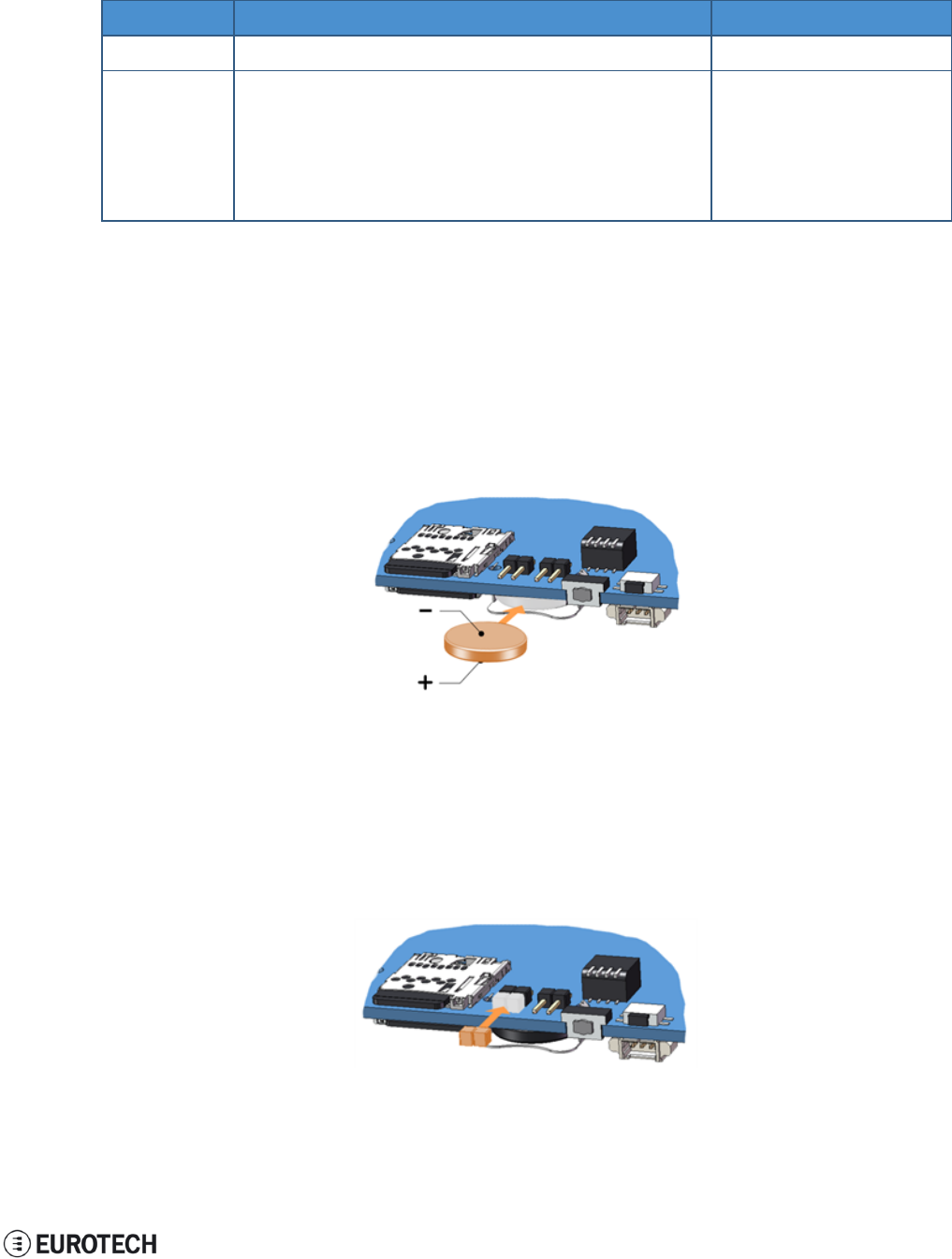
11.10.2 The RTC battery
The ReliaGATE 10-11-16 includes a BR1225 lithium coin cell RTC battery behind the Service Panel.
The RTC battery retains the timestamp for up to 180 days when the ReliaGATE 10-11-16 is powered off:
11.10.2.1 How to enable / disable the RTC battery
The ReliaGATE 10-11-16 includes an RTC battery jumper behind the Service Panel.
You can use the RTC battery jumper to enable / disable the RTC battery (this can be useful for example
when the ReliaGATE 10-11-16 is stored in the warehouse to save RTC battery charge):
lJumper inserted = Battery connected
lJumper removed = Battery not connected
43 / 68

11 Interfaces in detail ReliaGATE 10-11-16 User Manual Rev 1-0
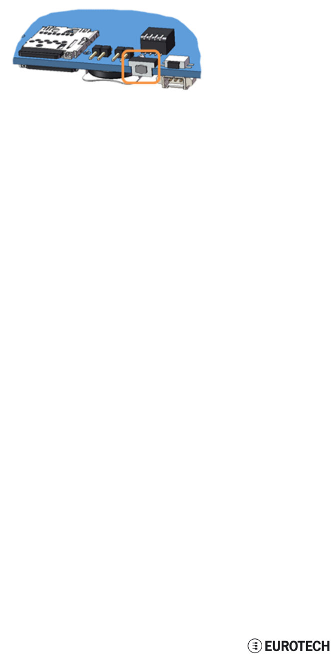
11.11 The Programmable pushbutton
Your ReliaGATE 10-11-16 includes a programmable pushbutton.
It is available behind the Service Panel.
The pushbutton is sensed by a Linux daemon which executes a shell script every time you push the
button.
44 / 68
ReliaGATE 10-11-16 User Manual Rev 1-0 11 Interfaces in detail
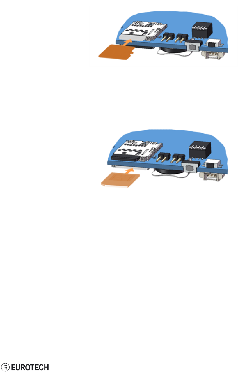
11.12 The MicroSD card receptacle
Your ReliaGATE 10-11-16 includes a push-push type Micro SD card receptacle.
This interface is available behind the Service Panel.
Insert the Micro SD card as in the picture below, with the contacts facing down.
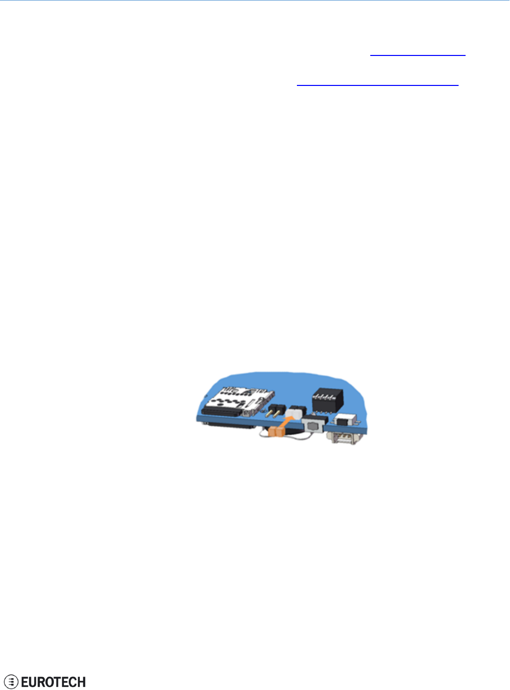
11.13 The MicroSIM card receptacle
Your ReliaGATE 10-11-16 includes a push-push type Micro SIM card receptacle.
This interface is available behind the Service Panel.
Insert the Micro SD card as in the picture below, with the contacts facing up.
45 / 68
11 Interfaces in detail ReliaGATE 10-11-16 User Manual Rev 1-0
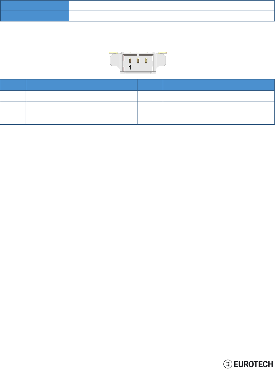
11.14 Debug Serial port
Your ReliaGATE 10-11-16 provides a debug TTL serial port (Linux OS console).
This interface is available behind the Service Panel.
11.14.1 Connector and mating connector specifications
Connector Molex 53261-0371
Mating connector Molex 51021-0300
11.14.2 Connector pinout
Pin# Name Type Description
1TX O Transmit Data
2RX I Receive Data
3DGND P Digital Ground
46 / 68

ReliaGATE 10-11-16 User Manual Rev 1-0 11 Interfaces in detail
11.15 Watchdog
Your ReliaGATE 10-11-16 includes a watchdog / supervisor IC, external to the CPU
47 / 68
(This page has been intentionally left blank)
ReliaGATE 10-11-16 User Manual Rev 1-0 12 Software
12 SOFTWARE
12.1 The Linux OS distribution
Eurotech provides a Linux operating systems based on Yocto framework (www.yoctoproject.org) as well
as an SDK for application development.
All the documentation for the developer is available from:www.yoctoproject.org/documentation.
12.2 The bootloader procedure
The bootloader procedure is the following:
1. The MLO file is loaded from either the external microSD card or the onboard eMMC memory, and
saved in the on-chip memory to configure the RAM memory for use
2. The u-boot.img file is loaded (from the same device where MLO was loaded from), saved in the
RAM memory, and executed
3. The bootloader searches for a valid operating system. The search order is:
a. microSD card
b. eMMC
4. The bootloader fetches the Linux kernel (/boot/zImage) and the device tree (/boot/reliagate-10-
11.dtb), and boots the operating system up
12.2.1 How to select the MLO source
The MLO file can be loaded from either the external microSD card or the onboard eMMC memory,
according to the setting of the Boot selection jumper (JP2):
lJP2 inserted = MLO file loaded from the micro-SD card
lJP2 removed = MLO file loaded from the eMMC and, if not found, from the microSD card
12.2.2 How to set up a correct microSD card / eMMC card partition
To allow the correct bootloader procedure, the microSD card and the eMMC memory have to be configured
with at least these 2 partitions:
l1st partition:
oType: FAT16
oFlags: lba, boot
oContains the files: MLO and u-boot.img
l2nd partition:
oType: ext4
oContains the operating system, including the Linux kernel (/boot/zImage) and the device tree
(/boot/reliagate-10-11.dtb)
49 / 68
(This page has been intentionally left blank)

ReliaGATE 10-11-16 User Manual Rev 1-0 13 Administrative console
13 ADMINISTRATIVE CONSOLE
This section describes how to log in the operating system using the administrative console (this can be
useful for diagnostic and system maintenance purposes).
This section also describes how to change the security settings after the initial setup.
The ReliaGATE 10-11-16 runs a Yocto project based Linux operating system.
You can log in the administrative console in one of the following ways:
lVia a Serial console (Console Port)
lVia a Remote login (over a network connection) via SSH (Secure SHell)
13.1 How to log in using the Serial console
To log in using the serial console, complete the following steps:
1. Connect a null modem serial cable from your development PC to the Serial Console on the
ReliaGATE device
2. Start a terminal emulation program such as TeraTerm on your development PC (minicom on a Linux
host). Configure the serial port connection for 115200, 8 bits, 1 stop bit, no parity, and no flow
control
3. Connect power supply to ReliaGATE device. The Power LED lights green when power is
successfully connected
4. Via the Uboot bootloader, the Linux kernel is found and launched automatically.
5. At the login prompt, enter username and password:
lDefault username (case sensitive): root
lDefault password (case sensitive): eurotech
13.2 How to log in using the Remote login
13.2.1 If your development PC is running Linux
To log in over a network connection, use an SSH client:
1. Enter the command ssh. The SSH client opens.
2. At the login prompt, enter username and password:
lDefault username (case sensitive): root
lDefault password (case sensitive): eurotech
NOTICE
If you are running a Linux host, by default theReliaGATE 10-11-16 runs zeroconf.
This means that you can detect the IP address of the unit remotely by running the command:
avahi-discover.
Example:
1. Run the the command: avahi-discover. A dialog box pops-up reporting all the devices
on your network that support this mechanism
2. Under "eth0 IPv4" > "local" > "Workstation", you should see your Reliagate’s hostname
(ie: rg-10-11). Select it to see its IP address
3. Log in your Reliagate using: ssh root@rg-10-11.local
51 / 68
13 Administrative console ReliaGATE 10-11-16 User Manual Rev 1-0
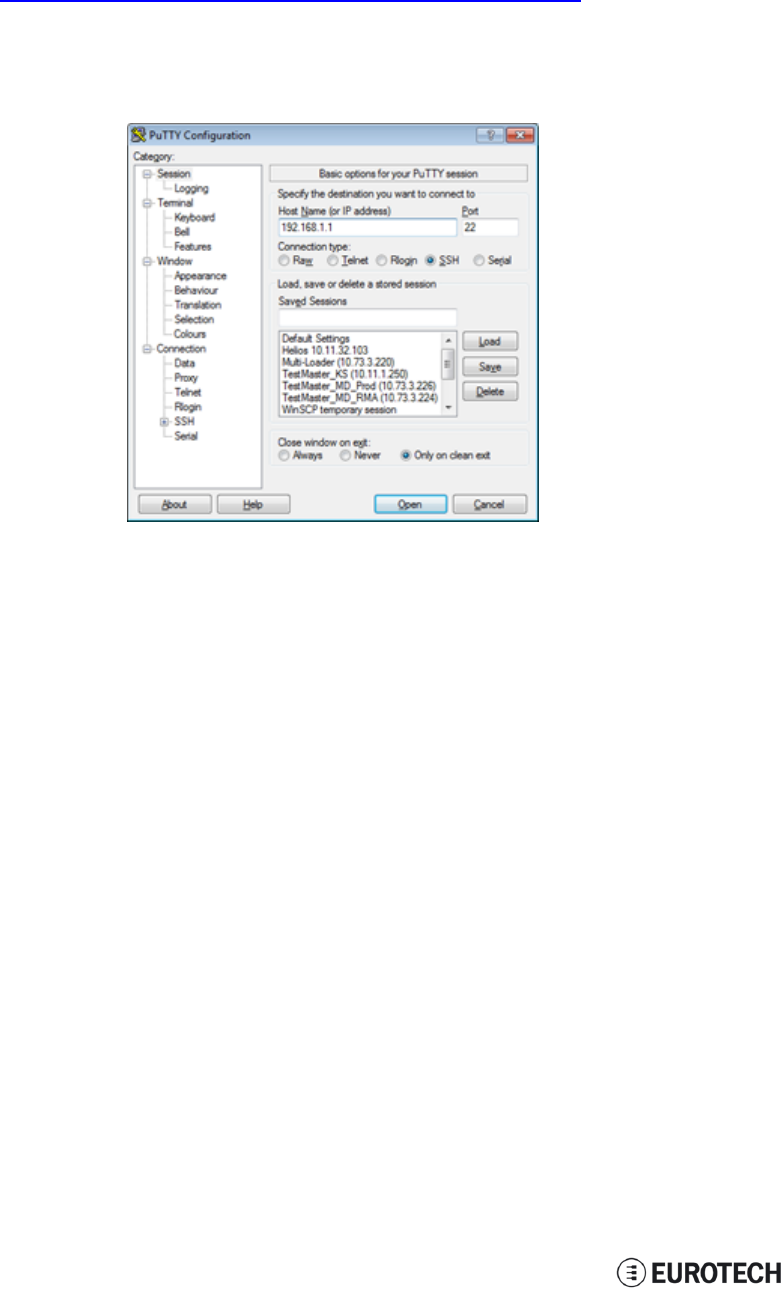
13.2.2 If your development PC is running Windows
To log in over a network connection, use an SSH client (you can use PuTTY, a free SSH client):
1. Download, install, and run PuTTY:
lChoose the Windows-based installer version from:
http://www.chiark.greenend.org.uk/~sgtatham/putty/download.html
2. Enter the IP address of the ReliaGATE 10-11-16:
lEthernet 0 (eth0 interface) acquires automatically the ReliaGATE 10-11-16 IP
address using DHCP
3. Set the Connection type to ‘SSH’ and Port to ‘22’. Click Open to connect
13.3 How to change your security settings
For security reasons, Eurotech recommends you to change the Linux password after your initial setup.
To change your Linux password, complete the followint steps:
1. At the login prompt, enter username and password:
lDefault username (case sensitive): root
lDefault password (case sensitive): eurotech
2. Use the command passwd to change the ‘root’ password
3. Enter a new ‘root’ account password when prompted
52 / 68
ReliaGATE 10-11-16 User Manual Rev 1-0 14 How to access to Linux peripherals
14 HOW TO ACCESS TO LINUX PERIPHERALS
14.1 Ethernet port
The ReliaGATE 10-11-16 exposes one 10/100 Mbps Ethernet port for wired network connectivity as
follows:
This interface is available on the rear panel:
lit is referenced as eth0, and aquires automatically the ReliaGATE 10-11-16 IP address using DHCP
14.2 Wi-Fi
The ReliaGATE 10-11-16 exposes the Wi-Fi interface as follows:
lWi-Fi: wlan0; not configured
14.3 Serial Ports
The ReliaGATE 10-11-16 exposes the serial ports as follows:
lConsole /dev/ttyO0
lSerial port1: /dev/ttyO3
lSerial port2: /dev/ttyO4
14.3.1 How to set the RS232/485 serial modes
Before you can use the serial ports, you have to configure them.
You can configure them in the following ways:
lusing the ethsetserial utility
limplementing the ioctl in the source code
14.3.1.1 Use the ethsetserial utility to configure the serial ports
To set Serial port 1 to RS232 mode, use the following command:
ethsetserial –p ttyO3 –m232
To set Serial port 1 to RS485 mode, use the following command:
ethsetserial –p ttyO3 –m485
To see all the available options, use the following command:
ethsetserial –h
14.3.1.2 Implement the ioctl in the source code to configure the serial ports
To implement the ioctl in the source code, see the following sections.
Ioctl codes
/*Ioctl to read */
#define TIOCGRS485 0x542E
/*Ioctl to write */
#define TIOCSRS485 0x542F
53 / 68

14 How to access to Linux peripherals ReliaGATE 10-11-16 User Manual Rev 1-0
Definition of the flags bit
/*FLAGS */
//#define SER_RS485_ENABLED (1 << 0)
/* Logical level for RTS pin when sending */
//#define SER_RS485_RTS_ON_SEND (1 << 1)
/* Logical level for RTS pin after sent*/
//#define SER_RS485_RTS_AFTER_SEND (1 << 2)
//#define SER_RS485_RX_DURING_TX (1 << 4)
/* Inverted logic level for RS485 gpio */
#define SER_RS485_INVERT (1 << 5)
/* if enabled serial line drivers must be configured in HiZ*/
#define SER_HIZ_ENABLED (1 << 31)
Linux kernel data structure
struct serial_rs485 {
__u32 flags; /* RS485 feature flags */
__u32 delay_rts_before_send; /* Delay before send (milliseconds) */
__u32 delay_rts_after_send; /* Delay after send (milliseconds) */
__u32 padding[5]; /* Memory is cheap, new structs
};
Example: Configure the serial port in RS232 mode
Use the example below to configure the serial port in RS232 mode.
ser_port_name can be either /dev/ttyO3 or /dev/ttyO4.
struct serial_rs485 rs485conf;
unsigned int rs_mode_mask=(SER_HIZ_ENABLED|SER_RS485_ENABLED|SER_RS485_
INVERT|SER_RS485_RTS_ON_SEND|SER_RS485_RTS_AFTER_SEND);
unsigned int set_flags=0;
unsigned int set_flags_mask=rs_mode_mask;
int fd;
fd=open(ser_port_name,O_RDWR);
if (fd==-1)
{
/* process the error */
…
}
/* get serial port configuration */
if (ioctl (fd, TIOCGRS485, & rs485conf) < 0)
{
/* process the error */
…
}
rs485conf.flags&=~ set_flags_mask;
set_flags&=set_flags_mask;
rs485conf.flags|= set_flags;
54 / 68

ReliaGATE 10-11-16 User Manual Rev 1-0 14 How to access to Linux peripherals
/*set delay but not used in rs232 mode */
rs485conf.delay_rts_after_send=<delay after send in ms>;
rs485conf.delay_rts_before_send=<delay before send in ms>;
/* apply changes */
if (ioctl (fd, TIOCSRS485, & rs485conf) < 0)
{
/* process the error */
…
}
close(fd);
Example: Configure the serial port in RS485 mode
Use the example below to configure the serial port in RS485 mode.
ser_port_name can be either /dev/ttyO3 or /dev/ttyO4.
struct serial_rs485 rs485conf;
unsigned int rs_mode_mask=(SER_HIZ_ENABLED|SER_RS485_ENABLED|SER_RS485_
INVERT|SER_RS485_RTS_ON_SEND|SER_RS485_RTS_AFTER_SEND);
unsigned int set_flags=(SER_RS485_INVERT|SER_RS485_ENABLED|SER_RS485_RTS_ON_
SEND);
unsigned int set_flags_mask=rs_mode_mask;
int fd;
fd=open(ser_port_name,O_RDWR);
if (fd==-1)
{
/* process the error */
…
}
/* get serial port configuration */
if (ioctl (fd, TIOCGRS485, & rs485conf) < 0)
{
/* process the error */
…
}
rs485conf.flags&=~ set_flags_mask;
set_flags&=set_flags_mask;
rs485conf.flags|= set_flags;
/*set delays */
rs485conf.delay_rts_after_send=<delay after send in ms>;
rs485conf.delay_rts_before_send=<delay before send in ms>;
/* apply changes */
if (ioctl (fd, TIOCSRS485, & rs485conf) < 0)
{
/* process the error */
…
}
close(fd);
55 / 68
14 How to access to Linux peripherals ReliaGATE 10-11-16 User Manual Rev 1-0
14.4 Modem
By default the ReliaGATE 10-11-16 exposes the modem as follows:
lAT commands port (data communication): /dev/ttyACM0
lGPS port: /dev/ttyACM3
14.5 CAN Bus
The ReliaGATE 10-11-16 exposes the CAN bus (added through the SocketCAN kernel extension) as
follows:
lCAN 0: /sys/class/gpio/gpio8/value
lCAN 1: /sys/class/gpio/gpio9/value
14.5.1 How to enable the CAN bus 5V
To enable CAN0 5V, use the following commands:
echo 1 >/sys/class/gpio/gpio8/value
To enable CAN1 5V, use the following commands:
echo 1 >/sys/class/gpio/gpio9/value
For further information on SocketCAN refer to the Linux kernel documentation:
www.kernel.org/doc/Documentation/networking/can.txt
56 / 68
ReliaGATE 10-11-16 User Manual Rev 1-0 14 How to access to Linux peripherals
14.6 Digital I/Os
The ReliaGATE 10-11-16 exposes the Digital I/Os as follows:
lInput 1: /sys/class/gpio/gpio87/value
lInput 2: /sys/class/gpio/gpio89/value
lOutoput 1: /sys/class/gpio/gpio26/value
lOutoput 2: /sys/class/gpio/gpio27/value
14.7 LED indicators
The ReliaGATE 10-11-16 exposes the LED indicatiors as follows:
lLED 1 (green): /sys/class/gpio/gpio117/value
lLED 2 (green): /sys/class/gpio/gpio114/value
lLED 3 (red): /sys/class/gpio/gpio115/value
lLED 4 (red): /sys/class/gpio/gpio116/value
lLED 5 (red): LED ON means modem ON;
LED blinking means modem attached to GSM network.
lLED 6 (green): LED ON means ReliaGATE ON
14.7.1 How to drive a LED
Each LED is m,anaged by its respective GPIO
To drive a LED, complete the following steps:
1. Export the LED (if it hasn’t already exported before)
2. Drive the LED
To export LED1, use the following commands:
#export gpio 117
echo 117 >/sys/class/gpio/export
#gpio is output
echo out >/sys/class/gpio117/direction
To drive LED1, use the following commands:
#turn led on
echo 1 >/sys/class/gpio117/value
#turn led off
echo 0 >/sys/class/gpio117/value
14.8 Flash Memory
The ReliaGATE 10-11-16 exposes the flash memory as follows:
lInternal flash (eMMC) memory: /dev/mmcblk0
lMicroSD card memory: /dev/mmcblk1
57 / 68
14 How to access to Linux peripherals ReliaGATE 10-11-16 User Manual Rev 1-0
14.9 Watchdog
The ReliaGATE 10-11-16 exposes the watchdog as follows:
lWatchdog: /dev/watchdog1
14.9.1 Manage the watchdog using the C programming language
To manage the watchdog using the C programming language use the following commands:
Int interval;
Int bootstatus;
Long value;
/* display current watchdog value */
If (ioctl(fd,WDIOC_GETTIMEOUT,&interval)==0)
{
// interval contains current timeout in seconds
}
/* Check if lasdt boot is caused by watchdog */
If (ioctl(fd,WDIOC_GETBOOTSTATUS,&bootstatus)==0)
{
//bootstatus <> 0 Watchdog
//bootstatus = 0 Power-on reset
}
/* set the watchdog value (for example: 30 seconds) */
value=30;
If (ioctl(fd,WDIOC_SETTIMEOUT,&value)==0)
{
//Watchdog has been set to value content
}
/* stop the watchdog */
write(fd,”V”,1);
/* feed the watchdog */
ioctl(fd,WDIOC_KEEPALIVE,0);
14.9.2 Manage the watchdog from the command line
To set the watchdog value (for example: 30 seconds), use the following command:
wdt_setup –d /dev/watchdog1 –t 30
To feed the watchdog, use the following command:
echo 10 >/dev/watchdog1
To stop the watchdog, use the following command:
echo V >/dev/watchdog1
58 / 68
ReliaGATE 10-11-16 User Manual Rev 1-0 14 How to access to Linux peripherals
14.9.3 For furhter information
For further information on Linux support for watchdog, see:
www.kernel.org/doc/Documentation/watchdog/watchdog-api.txt
14.10 RTC
The ReliaGATE 10-11-16 exposes the user-available RTC as follows:
lRTC: /dev/rtc1
The "/dev/rtc1" offers:
lthree timestamp registers
lone user-available byte.
14.10.1 How to use the timestamp registers
The timestamp registers are the following:
Timestamp register What it contains
sys/class/rtc/rtc1/device/timestamp1 Reserved data
sys/class/rtc/rtc1/device/timestamp2 The timestamp that the system last lost power (only if a
successful initialization has been achieved)
sys/class/rtc/rtc1/device/timestamp3 The timestamp that the system last has been powered
(only if a successful initialization has been achieved)
You can only read and reset the timestamp registers.
To read the timestamp2, use the following command:
cat /sys/class/rtc/rtc1/device/timestamp2
To reset the timestamp2, use the following command:
echo timestamp2 > /sys/class/rtc/rtc1/device/resets
59 / 68
14 How to access to Linux peripherals ReliaGATE 10-11-16 User Manual Rev 1-0
14.10.2 How to use the user-available byte
The user-available byte is the following:
User-available byte What it contains
/sys/class/rtc/rtc1/device/ram_byte The default value is 0.
You can write in it a value included in the range: 0 to 255.This
value is retained as long as the /dev/rtc1 device receives a
valid power supply (main power supply or battery)
You can read and write the user-available byte.
To read the byte, use the following command:
cat /sys/class/rtc/rtc1/device/ram_byte
To write 112 in the byte, use the following command:
echo 112 > /sys/class/rtc/rtc1/device/ram_byte
14.10.3 How to automaticallly wake the ReliaGATE 10-11-16 up from the sleep mode
To wake the ReliaGATE 10-11-16 up 20 seconds after the current date and time, use the following
commands:
#set current date
DATE=”09/04/2015”
TIME=”10:00:00”
date +”%m/%d/%y %H:%M:%s” –s “$DATE $TIME”
rtctest –d /dev/rtc1 –a “04/09/2015 10:00:20”
echo mem >/sys/power/state
14.11 EEPROM
You can use the EEPROMintegrated in the ReliaGATE 10-11-16 to read and write data.
NOTE: By default the EEPROM is write-protected.
14.11.1 How to enable / disable the EEPROM write-protection
The write-protection is managed by the GPIO 73.
To enable/disable the EEPROM write-protection, complete the following steps:
1. Export the GPIO 73
2. Drive the GPIO 73 to enable / disable the write-protection
To export the GPIO 73, use the following commands:
#export gpio 73
echo 73 >/sys/class/gpio/export
#set gpio as output
echo out >/sys/class/gpio73/direction
60 / 68

ReliaGATE 10-11-16 User Manual Rev 1-0 14 How to access to Linux peripherals
To drive the GPIO 73, use the following commands:
#enable write-protection
echo 1 >/sys/class/gpio73/value
#disable write-protection
echo 0 >/sys/class/gpio73/value
61 / 68
(This page has been intentionally left blank)
ReliaGATE 10-11-16 User Manual Rev 1-0 15 Mechanical specifications
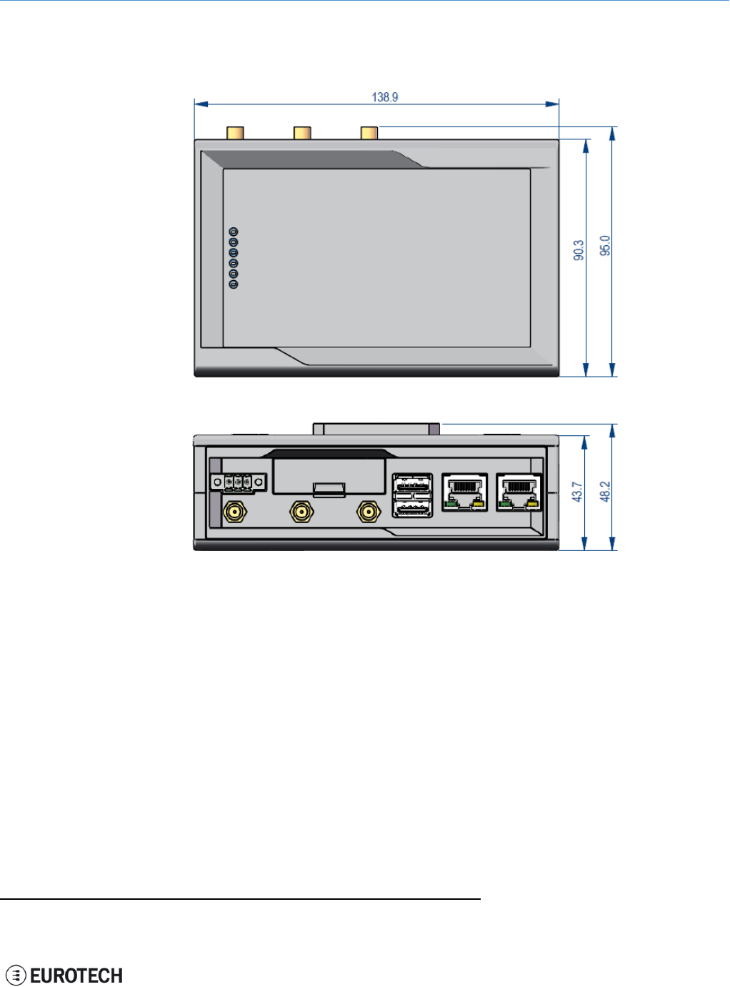
15 MECHANICAL SPECIFICATIONS
The ReliaGATE 10-11-16 electronics are housed in an ABS enclosure having the following dimensions:
139 (L) x 95 (W) x 48 (H); mm (DINmounting kit installed and connectors included1).
All dimensions are in millimeters.
Figure 15.1 - Mechanical dimensions
1The figure above shows the rear panel of the ReliaGATE 10-11 fully populated. Not all interfaces may be available in
your ReliaGATE 10-11 version.
63 / 68
(This page has been intentionally left blank)
ReliaGATE 10-11-16 User Manual Rev 1-0 16 Install / remove the product
16 INSTALL /REMOVE THE PRODUCT
16.1 Install the ReliaGATE 10-11-16 on a DIN rail
The ReliaGATE 10-11-161comes equipped with a mechanical adapter - the DIN mounting kit - that allows
you to install the product on a DIN rail.
To install the ReliaGATE 10-11-16 on a horizontal DIN rail, complete the following steps:
1. Hook the upper mobile latches of the mechanical adapter on the upper edge of the din rail
2. Push the ReliaGATE 10-11-16 against the DIN rail. The lower latches of the mechanical adapter are
locked on the din rail.
16.2 Remove the ReliaGATE 10-11-16 from a DIN rail
To remove the ReliaGATE 10-11-161from a horizontal DIN rail, complete the following steps:
1. Push the upper mobile latches of the mechanical adapter downwards. The lower latches are
released from the DIN rail
2. Pull the ReliaGATE 10-11-16 out
1The figures above show the rear panel of the ReliaGATE 10-11 fully populated. Not all interfaces may be available in
your ReliaGATE 10-11 version.
65 / 68
16 Install / remove the product ReliaGATE 10-11-16 User Manual Rev 1-0
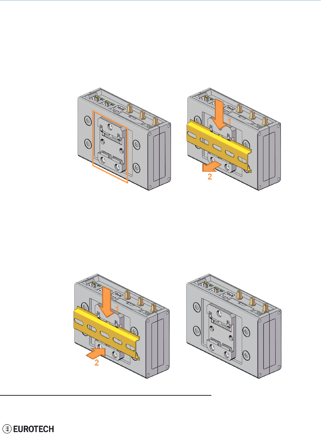
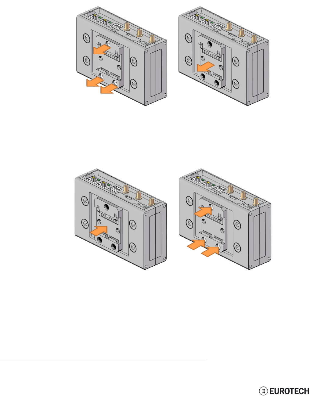
16.3 Remove the DIN mounting kit from the ReliaGATE 10-11-16
To remove the DIN mounting kit from the ReliaGATE 10-11-161, complete the following steps:
1. Remove the three screws that keep the DIN mounting kit in place
2. Remove the DIN mounting kit
16.4 Install the DIN mounting kit on the ReliaGATE 10-11-16
To install the DIN mounting kit on the ReliaGATE 10-11-161, complete the following steps:
1. Put the DIN mounting kit in place
2. Tighten the three screws to keep the DIN mounting kit in place.
1The figures above show the rear panel of the ReliaGATE 10-11 fully populated. Not all interfaces may be available in
your ReliaGATE 10-11 version.
66 / 68

ReliaGATE 10-11-16 User Manual Rev 1-0 Notes
NOTES
67 / 68

WORLD SUPPORT EUROPE AMERICAS ASIA
HEADQUARTERS
EUROTECH
Via Fratelli Solari, 3/a
33020 Amaro (UD) - Italy
Tel: +39 0433.485.411
Fax: +39 0433.485.499
Email: support.it@eurotech.com
Web: www.eurotech.com
ITALY
EUROTECH
Tel: +39 0433.485.411
Fax: +39 0433.485.499
Email: sales.it@eurotech.com
Email: support.it@eurotech.com
Web: www.eurotech.com
UNITED KINGDOM
EUROTECH
Tel: +44 (0) 1223.403410
Fax: +44 (0) 1223.410457
Email: sales.uk@eurotech.com
Email: support.uk@eurotech.com
Web: www.eurotech.com
FRANCE
EUROTECH
Tel: +33 (0)4.72.89.00.90
Fax: +33 (0)4.78.70.08.24
Email: sales.fr@eurotech.com
Email: support.fr@eurotech.com
Web: www.eurotech.com
USA
EUROTECH
Tel: +1 800.541.2003
Tel: +1 301.490.4007
Fax: +1 301.490.4582
Email: sales.us@eurotech.com
Email: support.us@eurotech.com
Web: www.eurotech-inc.com
JAPAN
ADVANET
Tel: +81 86.245.2861
Fax: +81 86.245.2860
Email: sales@advanet.jp
Email: tsupport@advanet.jp
Web: www.advanet.jp
For your Eurotech local contact refer to: www.eurotech.com/contacts
For the Eurotech Global Support Center refer to: eurotech.desk.com
For the Eurotech Download Area refer to: eurotech.com/download
All trademarks and trade names are the property of their respective owners