EVERINT BT-MSOII Bluetooth Module User Manual
EVERINT Co.,Ltd. Bluetooth Module
UserManual.wiki
>
EVERINT
>
BT MSOII User Manual
User Manual
Navigation menu
Upload a User Manual
Namespaces
Wiki Guide
HTML
PDF
Info
Views
User Manual
Discussion / Help
Navigation
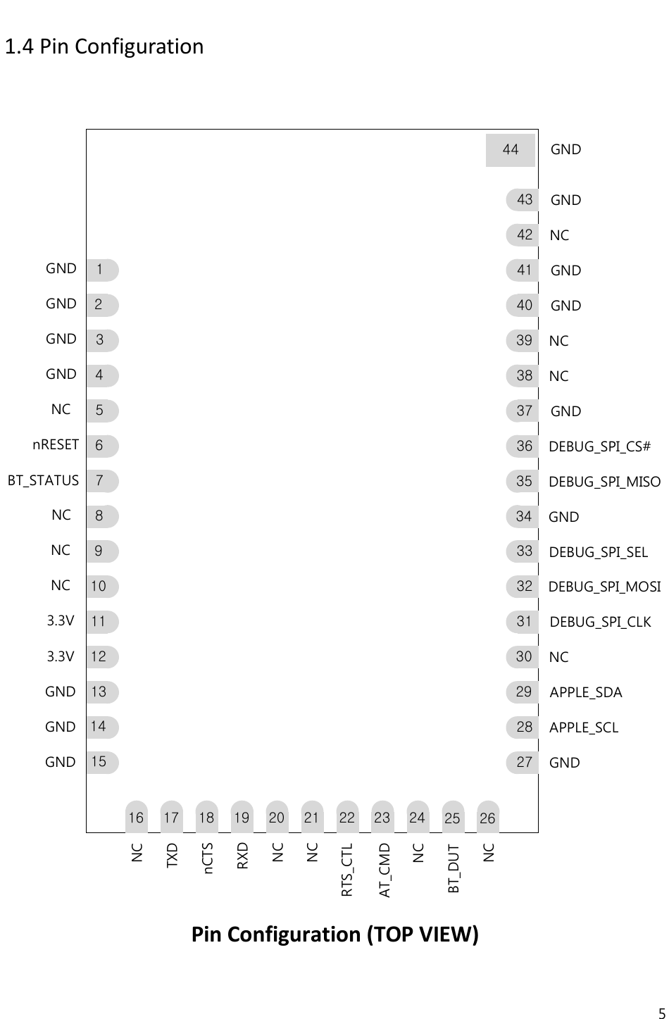
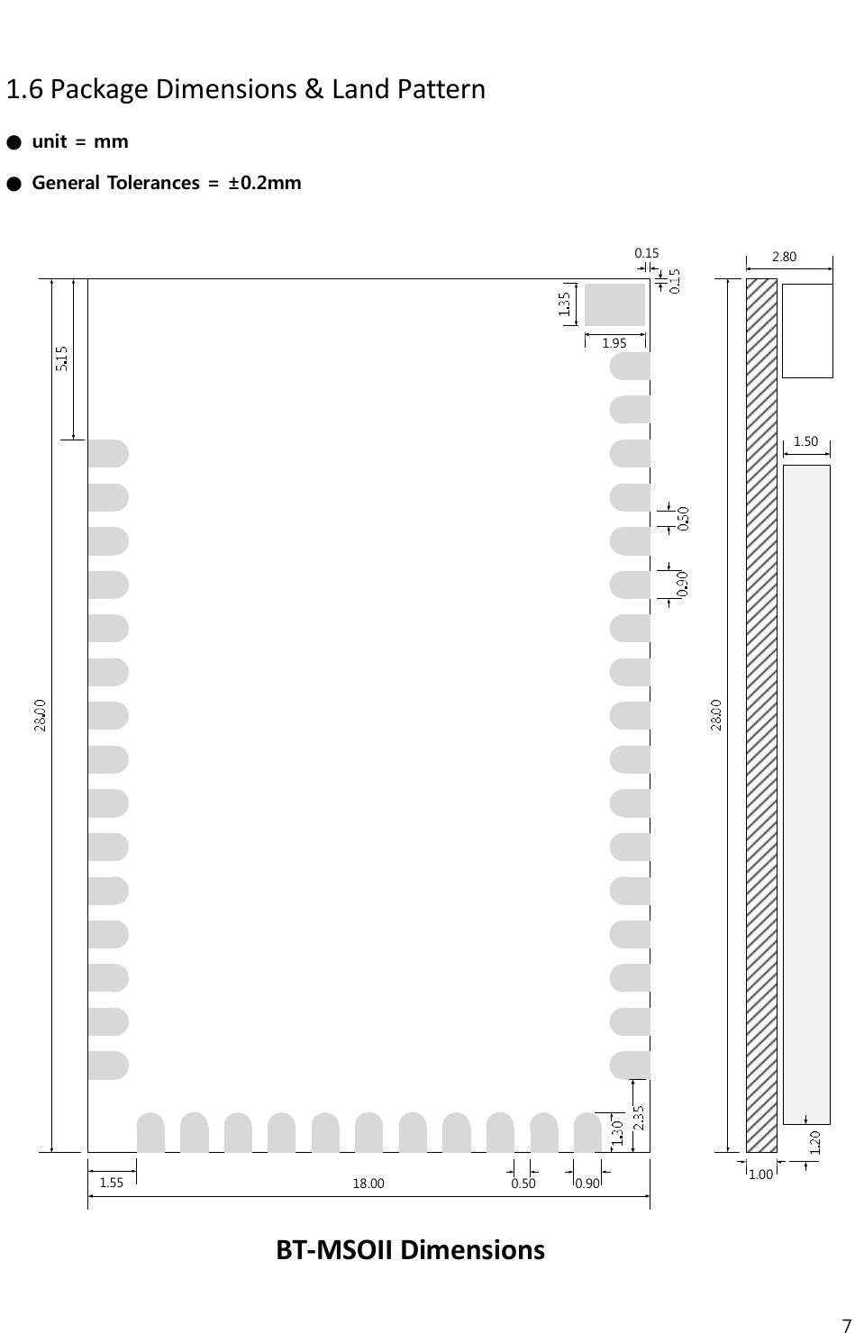
![6 1.5 Device Terminal Functions Pin Name Pin No. Pin type Description NoteBT_DUT 25 BT DUTBT_STATUS 7 BT_STATUSAT_CMD 23 AT CommandRTS_CTL 22 RTS ControlAPPLE_SDA 29 Apple MFi Chip Interface DataAPPLE_SCL 28 Apple MFi Chip Interface ClockDEBUG_SPI_MISO 35 Output, Weak Pull Down SPI Data OutputDEBUG_SPI_MOSI 32 Input, Weak Pull Down SPI Data InputDEBUG_SPI_CS# 36 Input, Weak Pull Down Chip Select Active LowDEBUG_SPI_CLK 31 Input, Weak Pull Down SPI ClockDEBUG_SPI_SEL 33 Input, Pull Up SPI SelectRXD 19 UART Data InputTXD 17 UART Data OutputnCTS 18 UART Clear to Send Active Low3V3 11,12 Positive Power SupplynRESET 6 Input, Stong Pull Up ResetBideirection,Weak Pull DownNC NC Not ConnectUART_RXFunction3V3RESETPIOPIO[13]PIO[14]PIO[15]5,8,9,10,16,20,21,24,26,3038,39,42OtherPinsPIO[16]Bideirection,Weak Pull UpBidirectionWeak Pull DownSPIInterfaceUARTInterfaceI2CInterfaceSPI_CS#SPI_CLKSPI_MISOSPI_MOSISDASCLSPI_SELGroundGND 1,2,3,4,13,14,15,27,34,3740,41,43,44UART_TXUART_CTSGROUND](https://usermanual.wiki/EVERINT/BT-MSOII/User-Guide-3244187-Page-6.png)