Eastman Kodak 81507E2537 8150 DryView Laser Imager Low Power Transmitter User Manual 7
Eastman Kodak Company 8150 DryView Laser Imager Low Power Transmitter 7
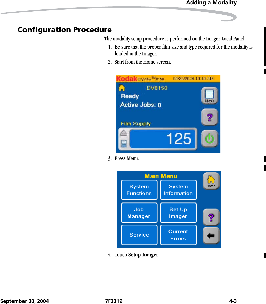
UserManual.wiki
>
Eastman Kodak
>
81507E2537 User Manual
>
user guide 2
Contents
1.
manual
2.
user guide 1
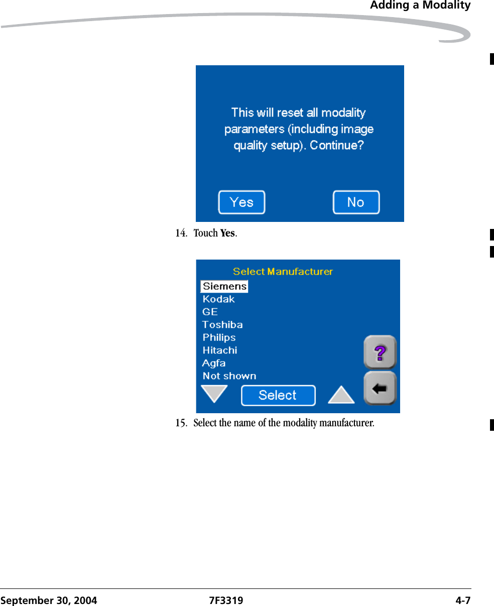
3.
user guide 2
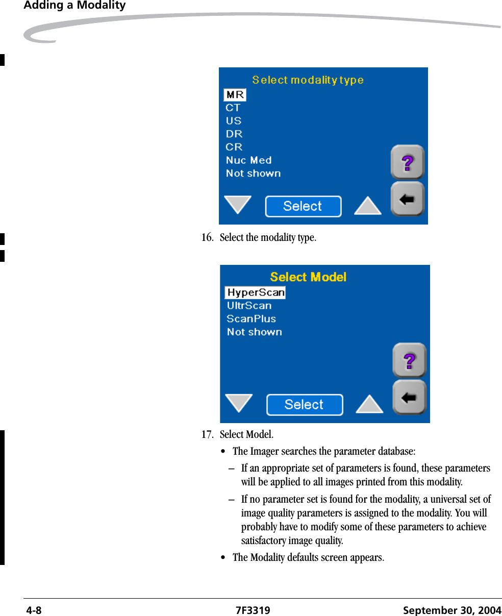
user guide 2
Navigation menu
Upload a User Manual
Namespaces
Wiki Guide
HTML
PDF
Info
Views
User Manual
Discussion / Help
Navigation
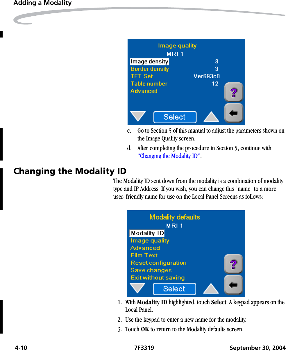
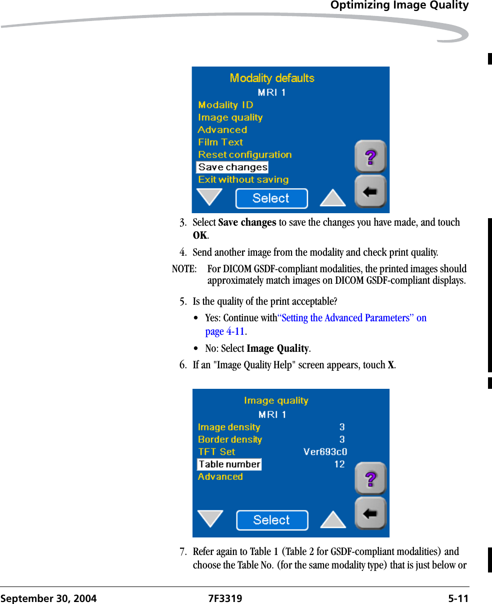
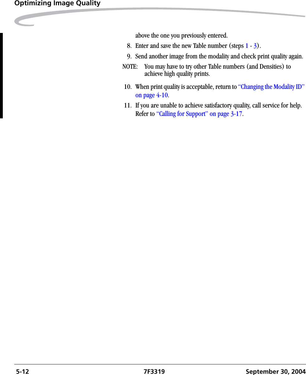
![Adding a ModalitySeptember 30, 2004 7F3319 4-918. Send another clinical image from the modality to the Imager.19. Wait for the Imager to print.20. Examine the quality of the print.21. Is the quality of the test print acceptable?•Yes - Go to “Changing the Modality ID” on page 4-10.•No - You can change image quality by adjusting individual image quality parameters:a. Select Image quality on the Modality defaults screen.b. If the above information screen appears, Touch [X]. The Image Quality screen appears.](https://usermanual.wiki/Eastman-Kodak/81507E2537.user-guide-2/User-Guide-484576-Page-29.png)