Eastman Kodak 81507E2537 8150 DryView Laser Imager Low Power Transmitter User Manual 7
Eastman Kodak Company 8150 DryView Laser Imager Low Power Transmitter 7
Contents
- 1. manual
- 2. user guide 1
- 3. user guide 2
user guide 2

September 30, 2004 7F3319 3-1
3
Troubleshooting
Correcting Errors
Occasionally errors (malfunctions), such as film jams, may occur in the
imager during print operations. You can easily correct minor problems. If
more serious malfunctions occur, you should contact a trained Authorized
Service Provider of Kodak products (see “Calling for Support” on
page 3-17).
Error and Alarm
Indications The Imager can detect malfunctions and other conditions that require
operator action. The Local Panel reports the presence of these errors or
abnormal conditions in several ways:
•Error Message screen
•Current Errors screen
•Current Errors notice on the Home screen
•Home screen status messages
Home Screen Status
Messages
For a description of the status information reported on the Home screen,
see “Home Screen Status Line” on page 2-14. Most of these status messages
do not report errors or abnormal conditions, but they do give information
about the current state of the Imager that may be useful for troubleshooting.
Status information about the film supply and film tray is displayed within the
Film Tray button on the Home screen. For a description, refer to “Film
Supply Button Status Information” on page 2-12.
3-2 7F3319 September 30, 2004
Troubleshooting
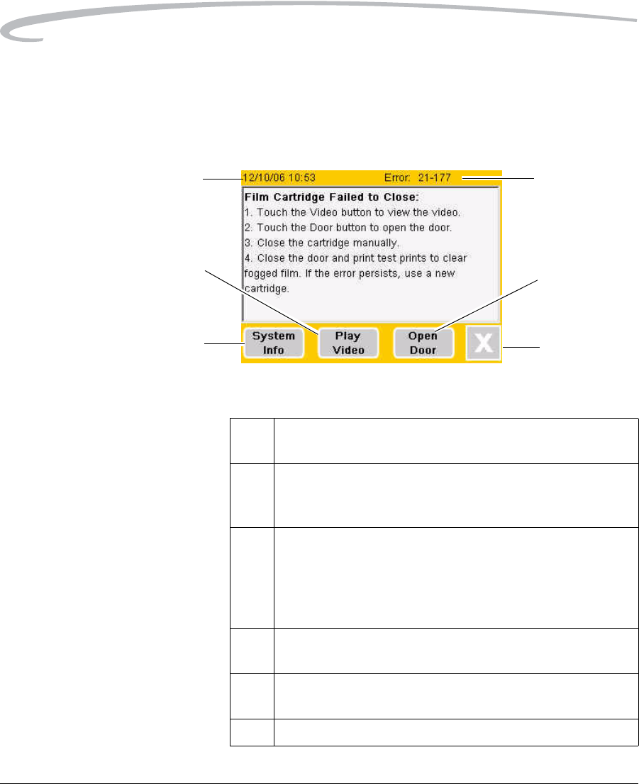
Error Message Screen The Error Message screen is the main error reporting mechanism for the
Imager. When the Imager detects an error, an alarm sounds and the Local
Panel displays an Error Message screen that describes the error and gives
a corrective action. Touch anywhere on the screen to silence the alarm.
Error Message Screen
6
4
2
3
1
5
Error Message Screen Details
1 Error Code. Identifies the type of error. Refer to this code when
calling for service.
2 Open Door button. Unlatches the front door. This button will
appear when the front door must be opened to correct the
reported error.
3X button. Closes the Error Message screen and moves to the
Current Errors screen, which lists any uncorrected errors in the
Imager. (See “Current Errors Screen” on page 3-4.) If you have
not corrected the error when you press X, the error will be listed
on the Current Errors screen.
4 System Info button. Opens the System Information menu
screen. (See “System Information Menu” on page 2-26.)
5 Play Video button. Plays a short video that explains how to
correct the error. A video is not available for all errors.
6 Date and Time. When the error occurred.

Troubleshooting
September 30, 2004 7F3319 3-3
NOTE: If you close an Error Message screen without correcting the
current error, you can recall the Error Message from the
Current Errors screen. (See “Current Errors Screen” on
page 3-4.)
Operator Action When an error message is displayed:
1. Silence the alarm by touching anywhere on the Error Message
screen.
2. Perform the corrective action recommended on the screen. If this
does not clear the error, call for service. (See “Calling for Support” on
page 3-17.)
Note the error code and error message before you call for service.
The error message may direct you to perform one of the following actions:
• Restart the Imager.
1. Go to the Home screen.
2. Press the Power Off button.
3. Wait for the Local Panel to go blank.
4. Turn off the power switch on the back of the Imager and then turn it
back on.
• Open the front door manually. See “Opening the Front Door Manually”
on page 2-49.
• Close the film cartridge. See “Manually Closing the Film Cartridge” on
page 3-9.
3-4 7F3319 September 30, 2004
Troubleshooting
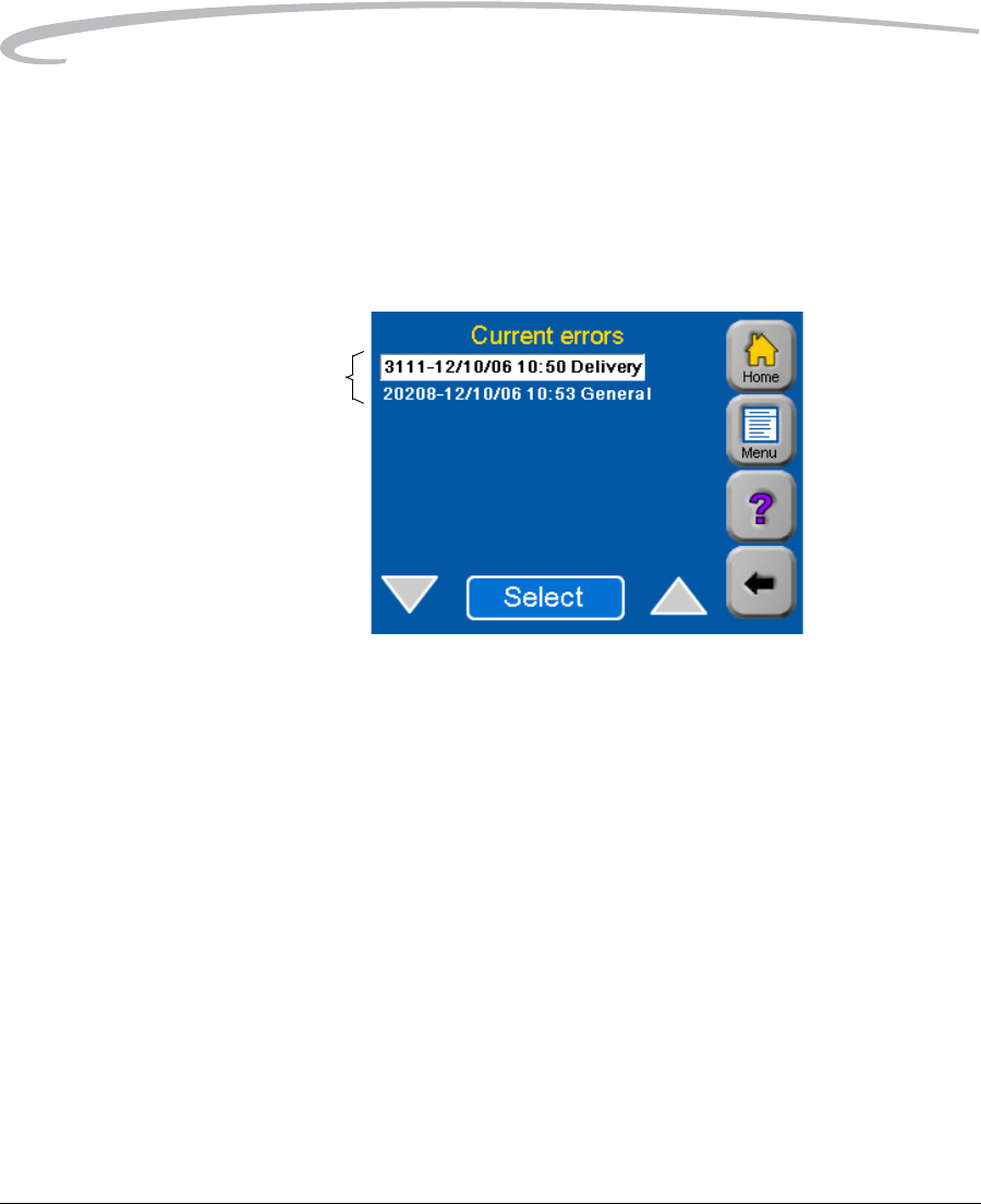
Current Errors Screen The Current Errors screen shows a list of uncorrected errors in the Imager.
To display this screen:
1. Press the Menu button.
2. On the Main Menu screen, press Current Errors.
The Current Errors screen appears:
Current Errors Screen
To see detailed information about any of the errors:
1. Highlight the error using the Up or Down arrow.
2. Touch Select.
The Error Message screen displays the error message for the error
you selected. (See “Error Message Screen” on page 3-2.)
List of Errors
Troubleshooting
September 30, 2004 7F3319 3-5
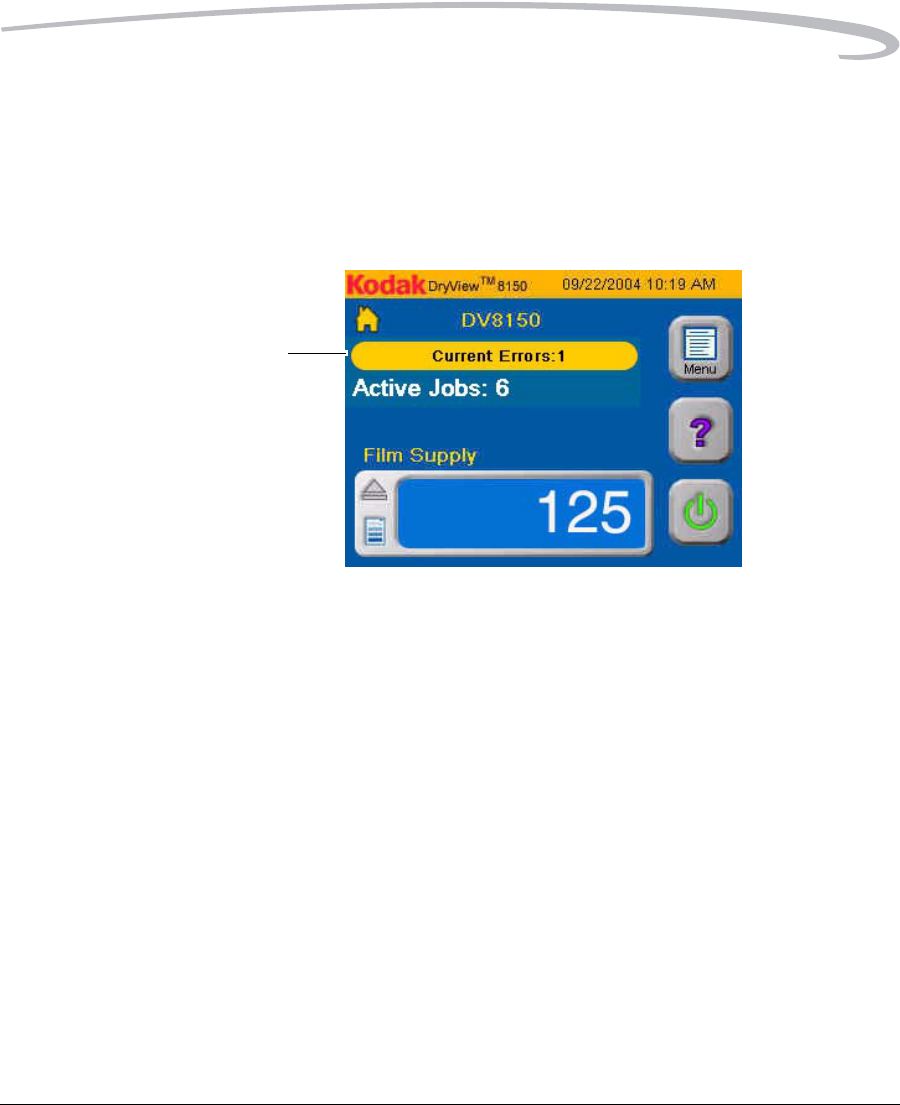
Current Errors Notice on the
Home Screen
When there are one or more uncorrected errors in the Imager, the Home
screen displays a Current Errors notice that shows the number of
uncorrected errors in the Imager.
To see a list of the current errors, you can display the Current Errors
screen. (See “Current Errors Screen” on page 3-4.)
Home Screen
Current Errors
Notice
3-6 7F3319 September 30, 2004
Troubleshooting
Calibration Failure
Periodically the Imager must be calibrated to ensure that internal settings
match the characteristics of the film in the Imager. Calibration is performed
by running a calibration print. The Imager runs a calibration print when:
• A film cartridge containing film with new sensitometric characteristics
(speed, contrast) is loaded.
• The Imager has not printed film for 7 days.
• The Dpatch (density patch) printed on the film is out of range.
The operator can also request a calibration print from the Local Panel.
For more information on calibration, see “Running a Calibration Print” on
page 2-53.
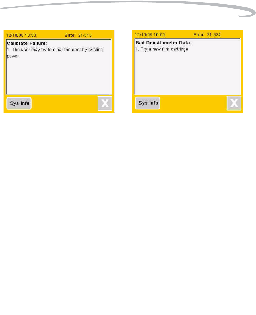
Occasionally, the Imager may fail calibration. When this occurs, the Local
Panel displays an error message screen. Depending on the cause of the
calibration failure, the Imager may or may not be able to continue
operating.
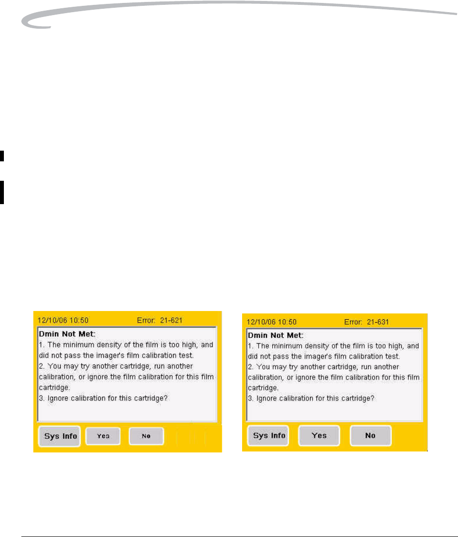
There are four conditions that cause calibration failure. The four error
message screens, below and on the next page, describe these error
conditions and show recommended operator actions.
These two errors indicate possible film aging. You can elect to continue
operation with the current film by touching Yes on the error screen.
Troubleshooting
September 30, 2004 7F3319 3-7
These two calibration errors indicate a major machine or film fault. The
Imager cannot continue to operate with the current film.
If you cannot restore normal operation by following the recommended
action on the error message screen, call for service. (See “Calling for
Support” on page 3-17.)
3-8 7F3319 September 30, 2004
Troubleshooting
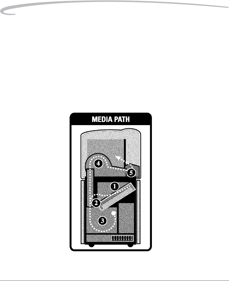
Film Transport Problems
The illustration below shows the path that film travels through the Imager
after the operator requests a print. The numbers in the illustration identify
key areas on the path through the five major areas in the Imager:
Area 1 – Film pickup from the cartridge
Area 2 – Film feed into the exposure area
Area 3 – Film feed out of the exposure area
Area 4 – Film feed into the processor
Area 5 – Film feed out of the processor and into the film tray
Film Drive Path
H188_1063GC
Troubleshooting
September 30, 2004 7F3319 3-9
Films may occasionally jam at various points along the film path. When a
film jam or film feed error occurs, an error message appears. The error
message identifies the area where a jam has occurred and recommends a
corrective action. The following information supplements the advice given
in the error messages for film feed problems.
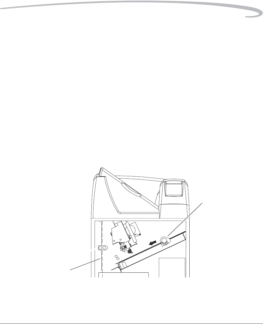
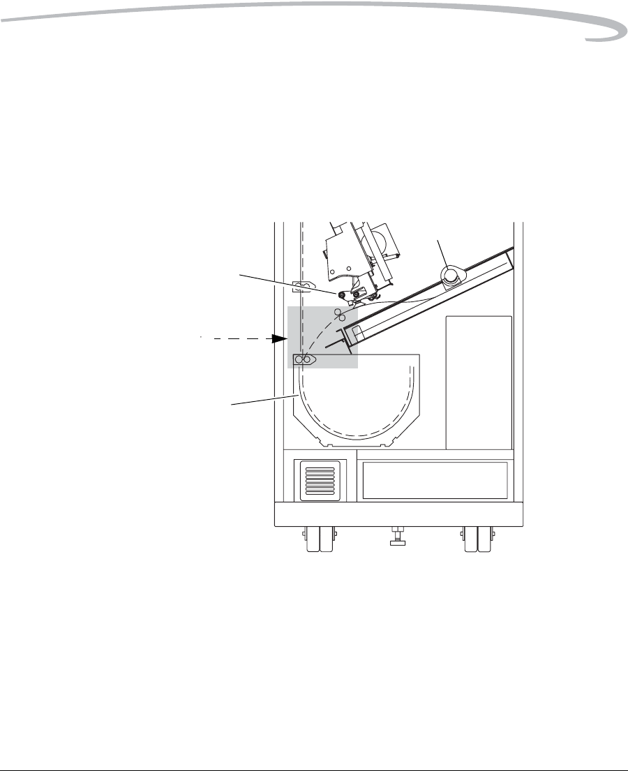
Manually Closing the Film Cartridge
When clearing film jams you may have to close the film cartridge manually.
Normally the Imager automatically closes the film cartridge when you press
the Open Front Door button. When a film jam occurs, the Imager may be
unable to close the cartridge. The front door then will not open.
When the film cartridge fails to close, an error message appears. Press the
Door Open button on the Error Message screen to unlock the front
door.
NOTE: If you open the front door when the film cartridge is open, the top
sheets of film in the cartridge are exposed. Before opening the
door, make the room as dark as possible to minimize exposure.
Manually Closing the Film Cartridge
1. Darken the room.
2. Open the front door.
H200_0004da
Film Path
(dashed line)
Rollback
Knob
3-10 7F3319 September 30, 2004
Troubleshooting
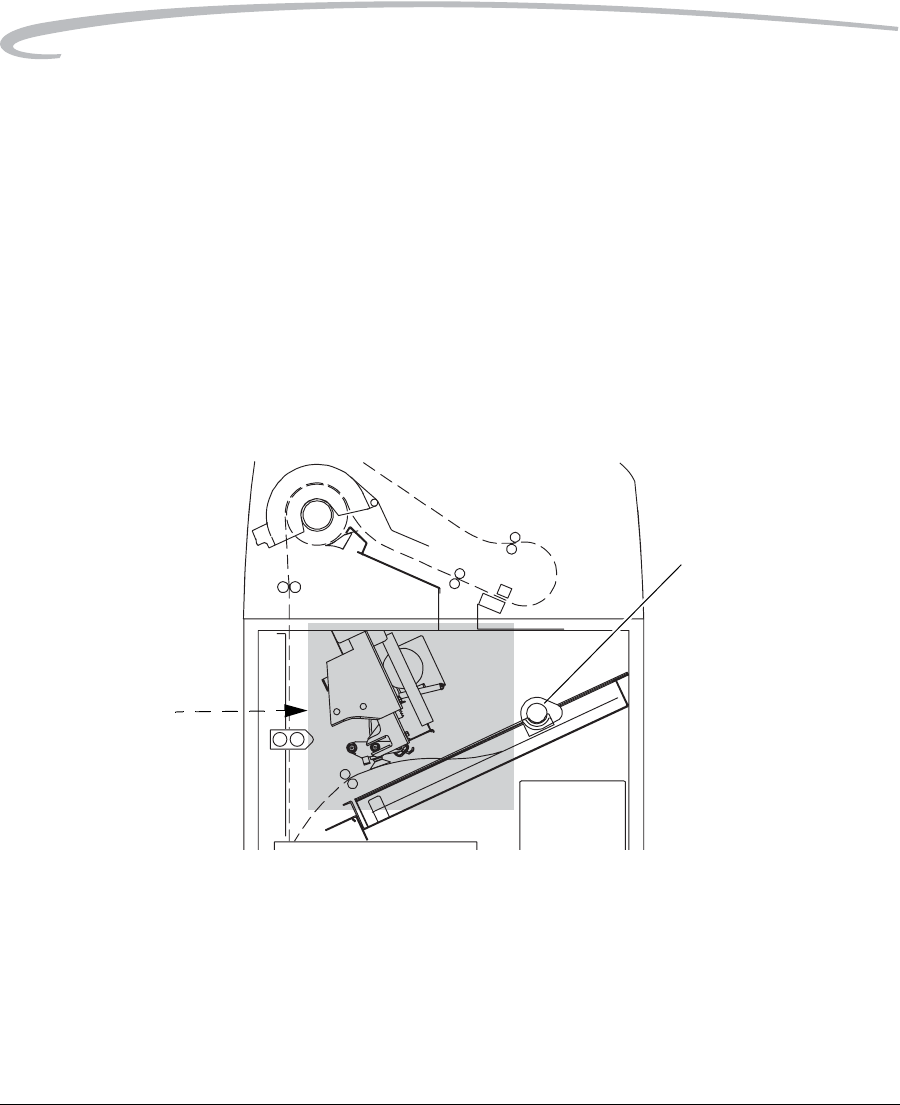
3. Clear any films that may be jammed in the film cartridge area.
4. Turn the rollback knob counterclockwise to close the cartridge.
Film Pickup Problems in Area 1
Area 1 is the location where film is removed from the film cartridge and
positioned to be sent by drive rollers toward the exposure area. If the
Imager cannot properly pick up a sheet of film and position it for drive,
error 21-116 (Pickup Fail) is declared. Error 21-177 (Cartridge Failed to
Close) also relates to Area 1.
NOTE: When problems occur in Area 1, the film cartridge is left open.
When you open the front door, the top sheets of film in the
cartridge will be exposed. Before opening the door, make the
room as dark as possible to minimize exposure.
Film Area 1
1. Press Door Open on the Error Message screen.
2. Remove any film outside the cartridge.
3. Turn the rollback knob counterclockwise to manually close the
cartridge lid.
4. Close the front door.
5. If you cannot resolve the problem, call for service. (See page 3-17.)
H200 0005d
Rollback
Area 1
Knob
Troubleshooting
September 30, 2004 7F3319 3-11
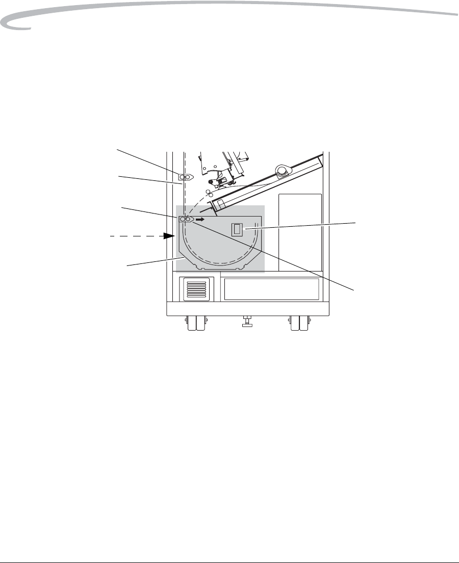
Removing Film Jams from Area 2
Area 2 in the Imager includes the path between the film pickup assembly
and the exposure platen.
NOTE: When jams occur in Area 2, the film cartridge is left open. When
you open the front door, the top sheets of film in the cartridge will
be exposed. Before opening the door, make the room as dark as
possible to minimize exposure.
Jam Area 2
1. Press Door Open on the Error Message screen.
2. Remove the jammed film.
3. Turn the rollback knob counterclockwise to manually close the
cartridge lid.
4. Close the front door.
H200_0006da
Rollback Knob
Film Pickup
Assembly
Exposure
Platen
Area 2
3-12 7F3319 September 30, 2004
Troubleshooting
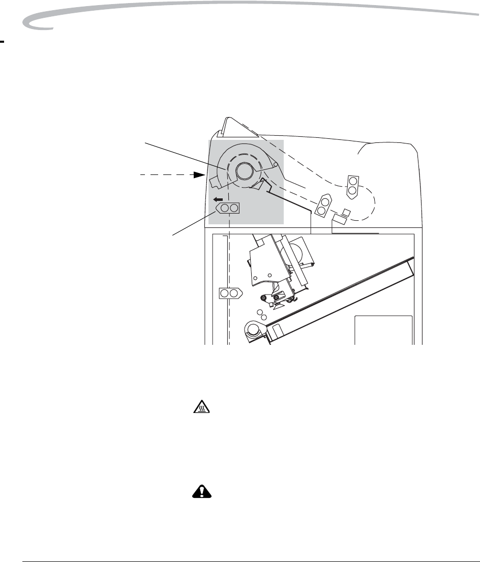
Removing Film Jams from Area 3
Area 3 includes the exposure platen. Jams in this area occur as film is
entering the platen before exposure, or as film is leaving the platen after
exposure. In rare cases, film may stall in the transport area above the
platen.
Jam Area 3
1. Open the front door.
NOTE: When film jams in this area, the cartridge may not close. If it does
not close, the front door will not unlock normally. You may have to
open the door manually (see “Opening the Front Door Manually”
on page 2-49). When the front door opens, the top sheets of film
in the cartridge will be exposed. Before opening the door, make
the room as dark as possible to minimize exposure.
2. If the film cartridge is open, turn the rollback knob counterclockwise
to manually close the cartridge lid.
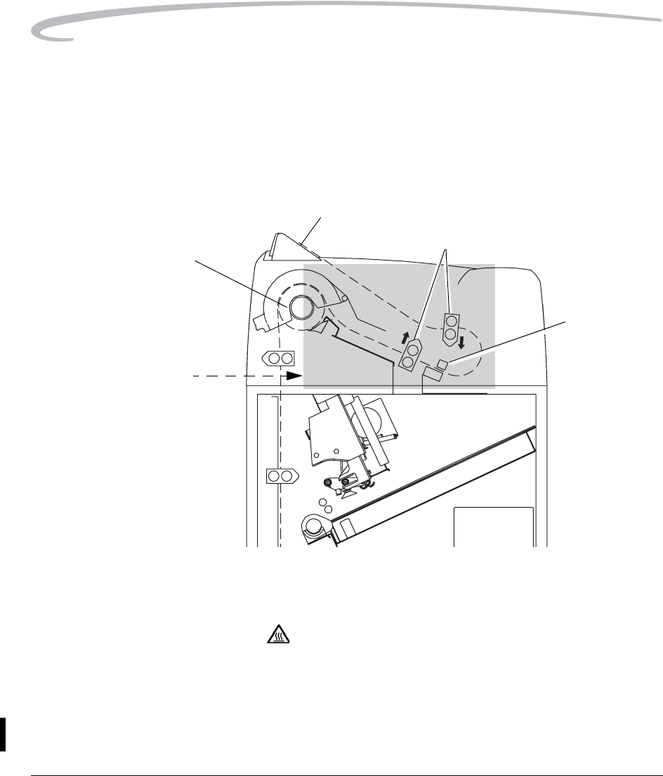
3. Clear the jammed film, if it is accessible.
4. If the film is not accessible:
a. Open the platen door by sliding the door latch to the left and pulling
out the platen door.
H200_0007da
Platen Door
Latch
Plastic Thumb
Tab 1
Plastic Thumb
Tab 2
Vertical
Transport
Platen Feed
Rollers
Area 3
Exposure
Platen
Troubleshooting
September 30, 2004 7F3319 3-13
b. Push the optics module toward the rear of the imager slowly and
smoothly.
c.Clear the film from inside the platen. If film is caught in the platen
feed rollers, pull Plastic Thumb Tab 1 (inside the platen door) to the
right. This opens the rollers and frees the film.
d. After clearing the jam, close the platen door.
5. If film is stalled in the vertical transport area, pull Plastic Thumb Tab 2
in this area to the right to open the rollers and free the film.
6. Close the front door.
Optics
Module
10 cm (4 in.)
3-14 7F3319 September 30, 2004
Troubleshooting
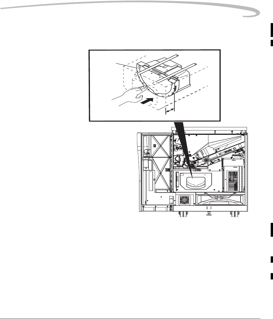
Removing Film Jams from Area 4
Area 4 includes the film processor.
When a jam occurs in this area all films in the Imager must be removed.
Jam Area 4
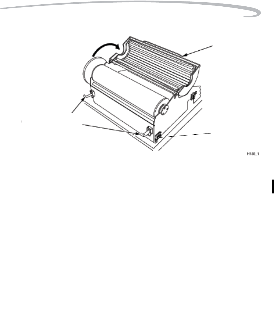
1. Open the hood.
CAUTION:
Drum and rollers inside the processor are hot. Exercise
caution when removing jammed film from the processor.
2. Release the two clamps at the left of the processor and open the drum
cover. (See the following figure).
CAUTION:
To prevent damage to the surface of the processor drum, do
not use any type of tool to remove jammed film.
H200_0008da
Processor
Drum
Area 4
Plastic Thumb
Tab
Troubleshooting
September 30, 2004 7F3319 3-15
Opening the Drum Cover
3. Clear the jammed film from the processor area (there may be more
than one sheet). If film is jammed in the drive rollers, pull the Plastic
Thumb Tab to the left to open the rollers and free the film.
4. Close the drum cover and secure it with the two clamps.
5. Remove any films in Area 5. (See page 3-16.)
6. Open the front door.
7. Remove all films in the lower part of the Imager.
8. Close the front door.
9. Close the hood.
The processor will have to warm to operating temperature before the
imager can resume printing.
Open
Clamps
Plastic Thumb
Tab
Open Drum
Cover
3-16 7F3319 September 30, 2004
Troubleshooting
Removing Film jams from Area 5
Area 5 consists of the components between the processor drum and the film
exit tray. Jams can occur in this area between the drum and the
densitometer, or in the densitometer. See the figure below.
When a jam occurs in this area all films in the imager must be removed.
Jam Area 5
1. Open the hood.
CAUTION:
Drum and rollers inside the processor are hot. Exercise
caution when working in the drum area.
2. Clear the jammed film from the processor area (there may be more
than one sheet). If film is jammed in the drive rollers, pull the Plastic
Thumb Tab to open the rollers and free the film.
H200_0009da
Densitometer
Plastic Thumb Tabs
Exit Tray
Processor
Drum
Area 5

Troubleshooting
September 30, 2004 7F3319 3-17
3. Remove any films in the processor. (See page 3-14.)
4. Close the hood.
5. Open the front door.
6. Remove all films in the lower part of the Imager.
7. Close the front door.
The processor will have to warm to operating temperature before the
imager can resume printing.
Calling for Support
If you cannot correct a malfunction and need help, call for support (see the
following table). Before you call, have the following information ready:
• Model number: 8150
• K-number: Displayed on the Local Panel System Information Screen
• Error code and error message if they are displayed on the Local Panel
Service Phone Numbers
Country Phone Number
Argentina 54-3327-458-195
54-3327-458-163
Austrailia 1 800 034 487
1 800 805 290
Austria 43.800291332
Azerbaijan 00 99412 410856
Belgium 32.27194116
Bolivia 54-3327-458-195
54-3327-458-163
Brazil 0800 15003
Canada 1-800-268-1567
Peoples Republic of China 800 820 5800
Cyprus 00 352 497777

3-18 7F3319 September 30, 2004
Troubleshooting
Czech Republic 420 236 100 307
420 62 335 426
Denmark 45 70206129
Finland 35.88001214
France 01 4001 4705
Germany 49.0180.3000.307
India 1600 118989
Iran 00 98 216 950821
00 98 216 402105
00 98 21 256 9741
00 98 21 256 9097
Ireland 44.01442 845775
Israel 00 972 3 9254040
Italy 39.02.66028000
Japan
0120-45-1881
Jordan 00 962 6 4545845
00 962 6 4543354
Netherlands 31.347.363900
Norway 47.66 81 80 80
Pakistan 00 92 21 2638881
Palistinian Territory 00 970 92387421
Paraguay 54-3327-458-195
54-3327-458-163
Portugal 351 21 414 7642
Qatar 00 974 4469 830
00 974 4360 820
Service Phone Numbers
Country Phone Number

Troubleshooting
September 30, 2004 7F3319 3-19
Romania 00 40 1210 3854
Saudi Arabia 00 966 2 682 8219
00 966 1 464 5064
Spain 902 19 03 99
Sweden 46.200.119.494
Switzerland 41.0800.804807
Syria 00 963 112128600
Tajikistan 00 90 216 578 2600
Turkey 90 216 572 54 33
Turkmenistan 00 90 216 578 2600
United Arab Emirates 00 971 6 746 6751
00 971 6 746 6285
United Kingdom 44 0442 84 6855
United States 800-328-2910
Service Phone Numbers
Country Phone Number
Blank Page

September 30, 2004 7F3319 4-1
4
Adding a Modality
After the Imager has been placed into service, you can later configure the
Imager to print images from additional modalities. The Imager is capable of
receiving images from twelve DICOM-compatible modalities concurrently.
Adding a modality involves adjusting some of the image quality settings in
the Imager to match the new modality. The following procedure explains
how to add one new modality.
NOTE: You must have the Service Passcode to perform this
procedure.
Preparing to Add a Modality
• Before you begin, make sure that the new modality has been set up to
print to the Imager. The Imager must be available as a print destination
in the modality print command.
• You will need the following information about the modality:
– The modality manufacturer
– The modality type (CT, MR, etc.)
– The modality model designation
– The type and size of film to be used
– Is the modality GSDF-compliant?
– If GSDF-compliant, does the modality use PLUTs for all images it
sends or only for some images?
• You should also decide on a screen name for the modality. This name
will be used only on the Imager Local Panel to identify the modality

4-2 7F3319 September 30, 2004
Adding a Modality
Modality-Related Parameters
The Imager must be configured to print from each connected modality. In
the Imager a set of modality-specific parameters must be created for each
modality that will print to the Imager.
For many modalities, the required parameters can be taken from the
"Modality Preferences Database" (MPDB). This internal database, within
the Imager, contains tested parameter sets for many commonly used
modalities.
Modality configuration is accomplished in three ways:
•First Print - When a modality prints to the Imager for the first time, the
Imager automatically attempts to identify the type of modality from
information included in the print job. If the Imager identifies the
modality, it searches for a parameter set in the MPDB. If an appropriate
parameter set is not found, the Imager assigns a universal set of
parameters to the modality. If the parameter set does not produce
acceptable prints, the installer can go on to the
"Manufacturer/Model/Type" procedure.
•Manufacturer/Model/Type - If the automatic search in the MPDB is
not successful, the installer can enter the Manufacturer, Model and Type
of the modality on the Local Panel. The Imager uses this information to
search the MPDB again for a set of parameters. A universal parameter
set is applied if an approprialte parameter set is not found. If the
parameter set is not acceptable, the Installer must use the Manual Entry
method.
•Manual Entry - The installer can enter or adjust individual modality
parameter values on several modality configuration screens.
For each of the above methods, the user must print a clinical image and
check image quality to determine if the parameter set is acceptable.
The user can use a combination of manual entry and one of the other two
methods. For example, the user may accept the "First Print" parameter set
but adjust one or two of the parameters manually to suit local preferences.
The parameter set selected using the above methods is placed in a
"Connection Database" in the Imager and used to print all images from the
modality. The Connection Database contains a separate parameter set for
each modality associated with the Imager.
Adding a Modality
September 30, 2004 7F3319 4-3
Configuration Procedure
The modality setup procedure is performed on the Imager Local Panel.
1. Be sure that the proper film size and type required for the modality is
loaded in the Imager.
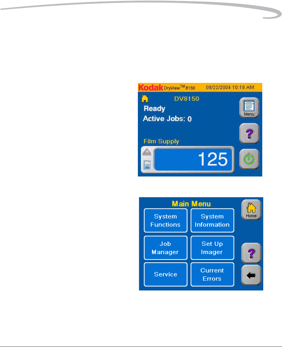
2. Start from the Home screen.
3. Press Menu.
4. Touch Setup Imager.
4-4 7F3319 September 30, 2004
Adding a Modality
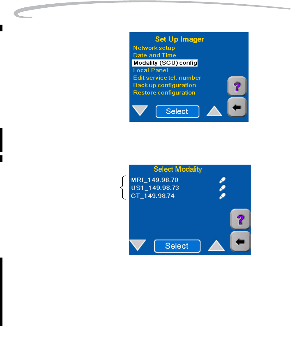
5. Select Modality (SCU) config.
6. Enter the Service User ID (99) and the Service Passcode on the
keypads that appear.
NOTE: If the new modality has previously printed to the Imager but has
not been configured, it will appear on the above list but without a
footprint symbol.
7. Send an Image from the new modality to the Imager.
• If this is the first time the new modality has printed to the Imager,
continue with step 8.
• If the modality has previously printed to the Imager, go to step 10
on page 4-6.
Previously Configured Modalities
Adding a Modality
September 30, 2004 7F3319 4-5
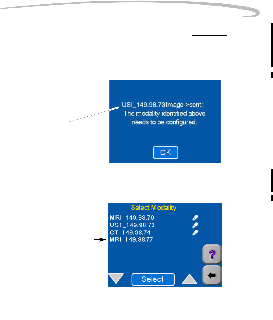
8. Wait for the following message screen to appear - about 1 minute.
(When a modality prints to the Imager for the first time, this message
will appear.)
NOTE: If this message does not appear, the modality may not be properly
set up to print to the Imager. Check the modality setup and re-send
the image.
9. Touch OK.
The modality that sent the image should now appear at the bottom of
the list of modalities.
IP Address of the
modality that has
printed to the Imager
New Modality - that just printed
4-6 7F3319 September 30, 2004
Adding a Modality
10. Wait for the Imager to print the image sent from the modality.
• The imager will attempt to find an appropriate set of parameters for
the modality in its internal database of modality parameters.
• If no parameter set is found for the modality, the Imager uses a
universal set of parameters to print the test image.
11. Examine the quality of the print. Determine if it is acceptable.
12. On the Select Modality screen (page 4-4), select the modality that
printed the image.
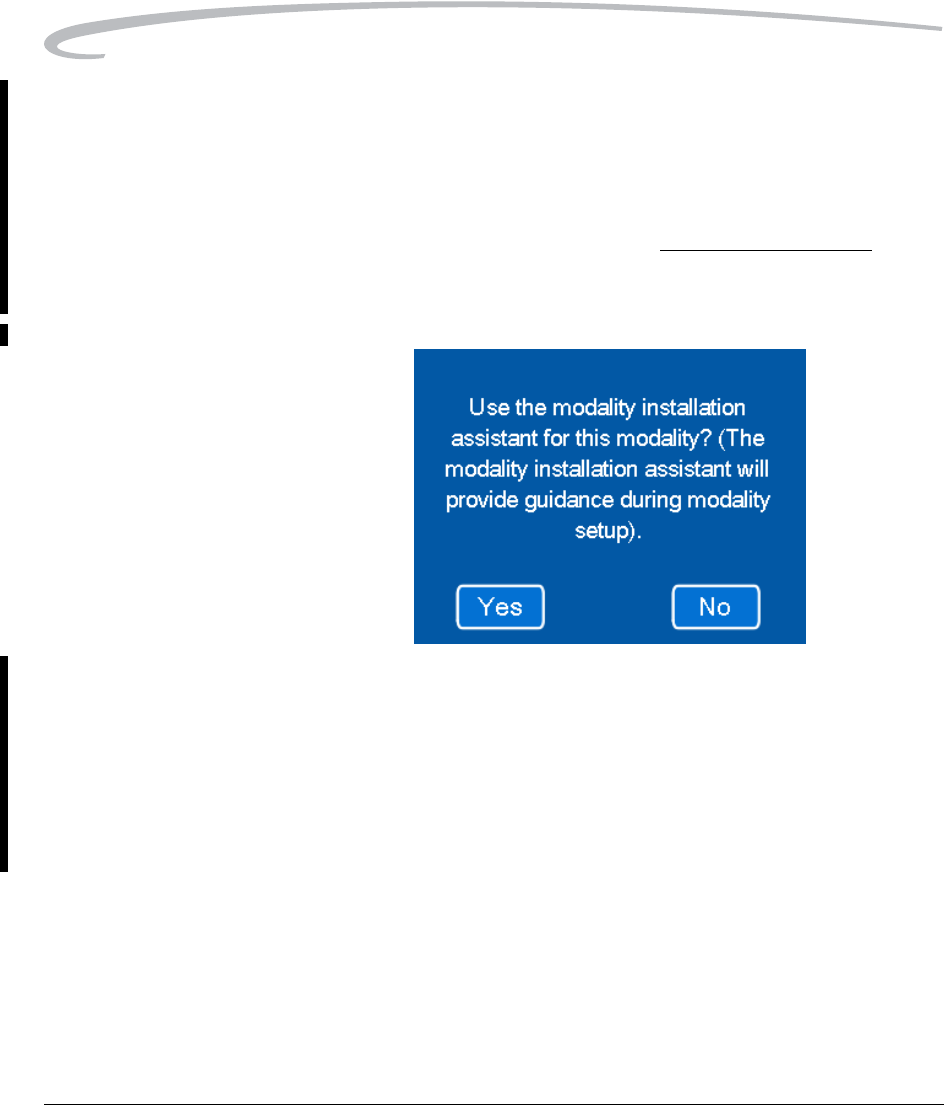
13. Is the quality of the print acceptable?
• If acceptable, touch No (do not use the modality installation
assistant). Go to “Changing the Modality ID” on page 4-10.
• If not acceptable, touch Yes (use the modality installation
assistant).
You will now see a series of screens that will allow you to enter the
Manufacturer, Type and Model of the modality. The Imager will use
this information for a second search of its parameter database.
Adding a Modality
September 30, 2004 7F3319 4-7
14. Touch Yes.
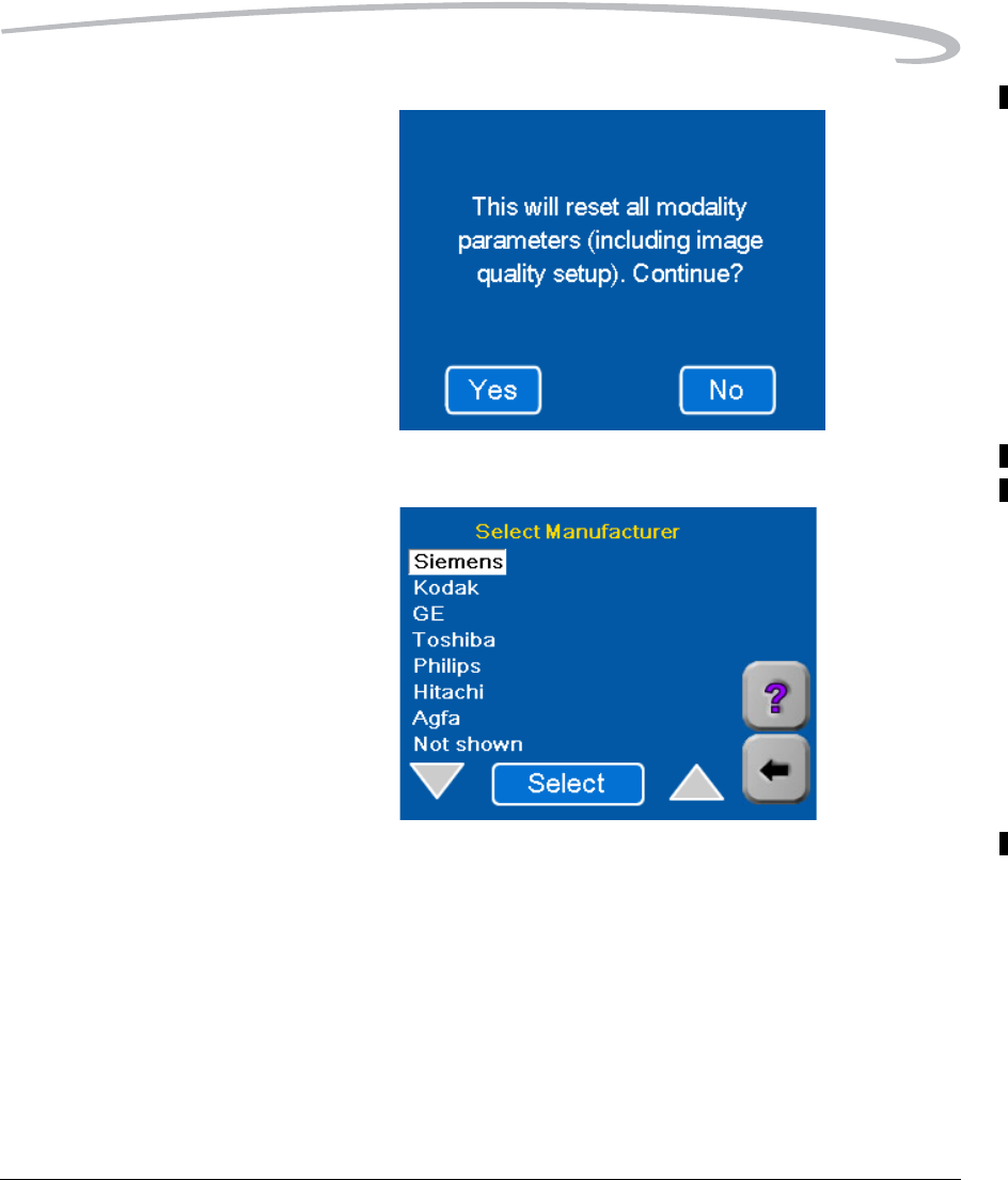
15. Select the name of the modality manufacturer.
4-8 7F3319 September 30, 2004
Adding a Modality
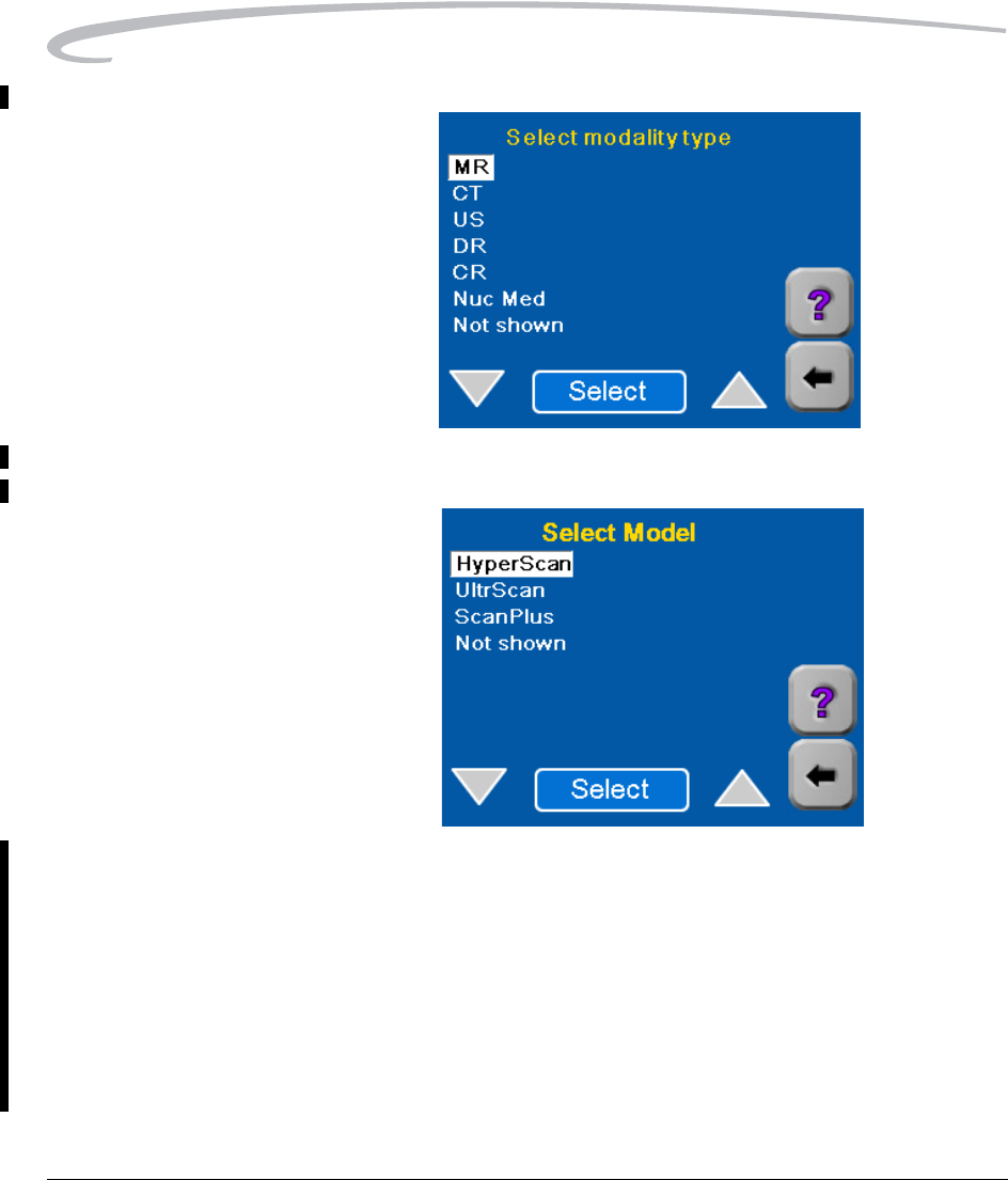
16. Select the modality type.
17. Select Model.
• The Imager searches the parameter database:
– If an appropriate set of parameters is found, these parameters
will be applied to all images printed from this modality.
– If no parameter set is found for the modality, a universal set of
image quality parameters is assigned to the modality. You will
probably have to modify some of these parameters to achieve
satisfactory image quality.
• The Modality defaults screen appears.
Adding a Modality
September 30, 2004 7F3319 4-9
18. Send another clinical image from the modality to the Imager.
19. Wait for the Imager to print.
20. Examine the quality of the print.
21. Is the quality of the test print acceptable?
•Yes - Go to “Changing the Modality ID” on page 4-10.
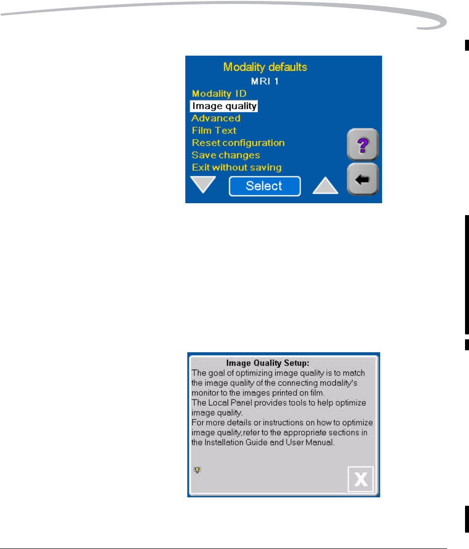
•No - You can change image quality by adjusting individual image
quality parameters:
a. Select Image quality on the Modality defaults screen.
b. If the above information screen appears, Touch [X].
The Image Quality screen appears.
4-10 7F3319 September 30, 2004
Adding a Modality
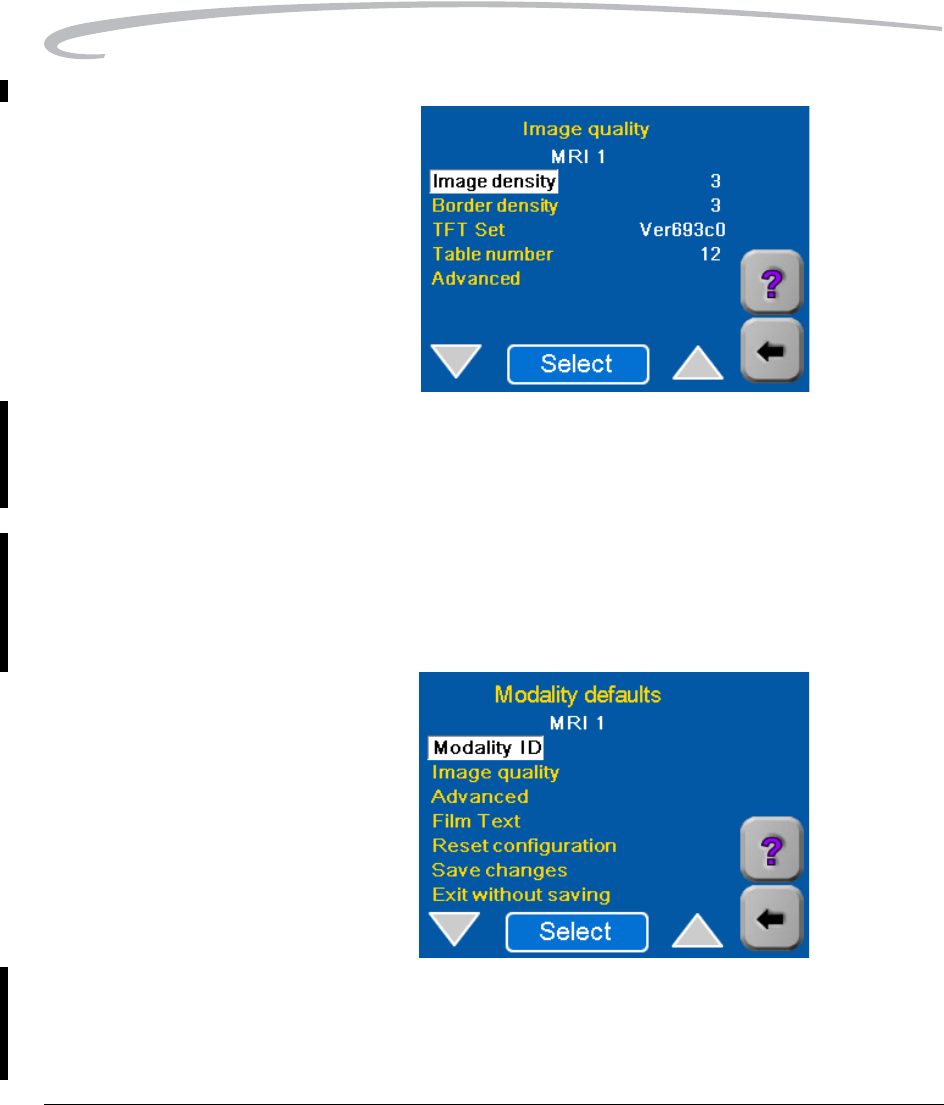
c. Go to Section 5 of this manual to adjust the parameters shown on
the Image Quality screen.
d. After completing the procedure in Section 5, continue with
“Changing the Modality ID”.
Changing the Modality ID
The Modality ID sent down from the modality is a combination of modality
type and IP Address. If you wish, you can change this "name" to a more
user- friendly name for use on the Local Panel Screens as follows:
1. With Modality ID highlighted, touch Select. A keypad appears on the
Local Panel.
2. Use the keypad to enter a new name for the modality.
3. Touch OK to return to the Modality defaults screen.
Adding a Modality
September 30, 2004 7F3319 4-11
Setting the Advanced Parameters
NOTE: The Imager automatically sets the Advanced default parameters for
a modality when you begin the modality setup process. In most
cases these settings are satisfactory. Do not change these
parameters unless you are certain that your application of the
modality requires different settings.
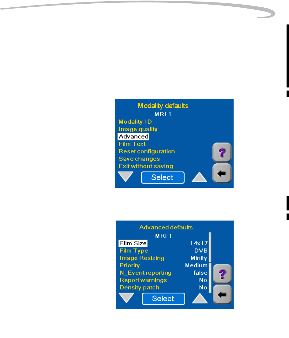
1. Return to the Modality defaults screen.
2. Select Advanced. A list of "Advanced" parameters with their currently
selected default values appears.
4-12 7F3319 September 30, 2004
Adding a Modality
Selecting Film Size The film sizes accepted by the Imager are 14 by 17 in., 11 by 14 in., and 14
by 14 in. If the default size shown on the screen is not the desired size,
change it.
1. On the Advanced defaults screen, highlight Film Size.
2. Use the Select button to choose the film size appropriate for this
modality. Each time you touch Select, the film size will change.
3. For most installations Override modality should be left at false.
NOTE: If you select True for Override modality, the Film Size set in
step 2 will take precedence over any film size requested by the
modality.
4. Touch the Back arrow to return to the Advanced defaults screen.
Adding a Modality
September 30, 2004 7F3319 4-13
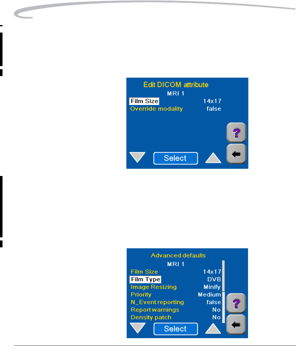
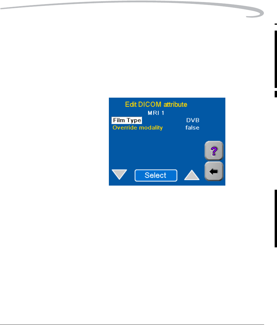
Selecting Film Type The Film Type choices are DVB (DryView Blue) and DVC (DryView Clear).
There is more than one type of Kodak DryView DVB film. The DVB choice
applies to all DVB and DVB+ film types.
If the default shown is not correct for this modality, change the value as
follows
1. On the Advanced defaults screen, highlight Film Type.
2. Touch Select. The Edit DICOM attribute screen appears.
3. Use the Select button to choose the type of film appropriate for this
modality.
4. For most installations Override modality should be left at false.
NOTE: If you select True for Override modality, the Film Type set in
step 3 will take precedence over any film type requested by the
modality.
5. Touch the Back arrow to return to the Advanced defaults screen.
4-14 7F3319 September 30, 2004
Adding a Modality
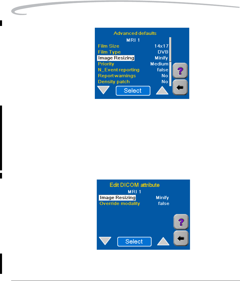
Selecting the Type of
Image Resizing
If the image sent down from the modality is too large for the size of film
installed in the Imager, the Imager can resize the image to fit on the film by
either of two methods:
•Minify - To reduce the image to fit on the selected film size.
•Crop - To remove the edges of the image to allow it to fit on the
selected page size.
For more information on these two methods, refer to “Image Resizing” on
page 2-45.
1. On the Advanced defaults screen, highlight Image Resizing.
2. Touch Select to display the Edit DICOM attribute screen.
3. Use the Select button to choose the desired resizing option (Minify
or Crop).
Adding a Modality
September 30, 2004 7F3319 4-15
4. For most installations Override modality should be left at false.
NOTE: If you select True for Override modality, the Image Resizing
mode set in step 3 will take precedence over any type of sizing
requested by the modality.
5. Touch the Back arrow to return to the Advanced defaults screen.
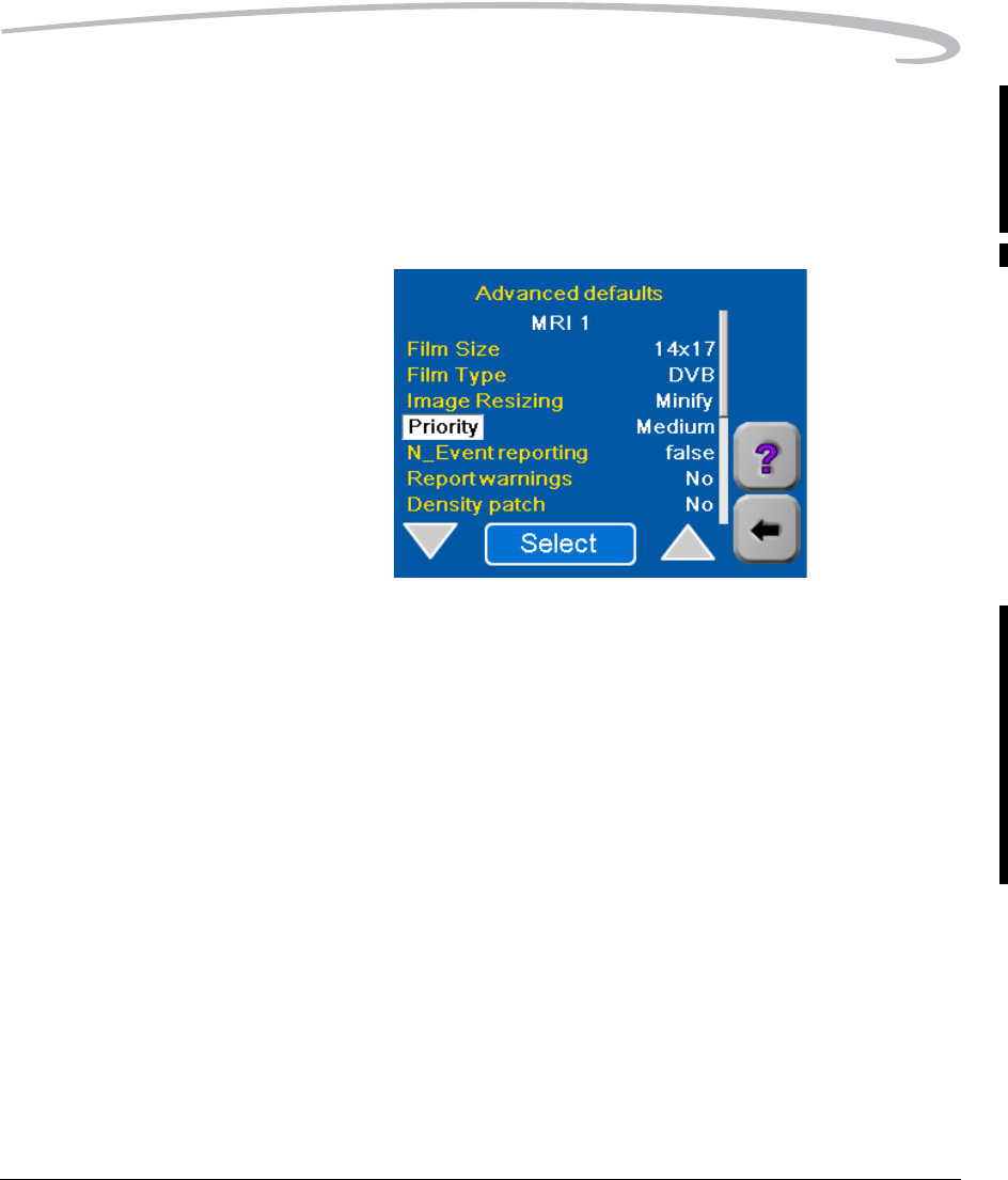
Selecting Print Priority The Priority for prints determines the order in which the Imager will
process prints if a number of modalities are requesting prints at the same
time. You can select one of three priority levels.
• High - Prints from this modality will take precedence over prints from
modalities with lower priority.
• Low - Prints from modalities with higher priorities will take precedence.
• Medium - Prints from this modality have "medium" priority.
1. On the Advanced defaults screen, highlight Priority.
2. Touch Select to display the Edit DICOM attribute screen.
4-16 7F3319 September 30, 2004
Adding a Modality
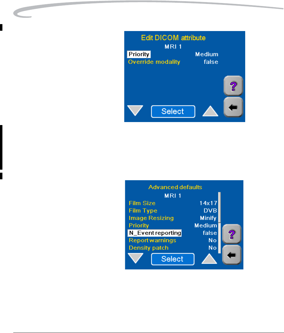
3. Use the Select button to choose the desired priority for printing.
4. For most installations Override modality should be left at false.
NOTE: If you select True for Override modality, the priority set in step
3 will take precedence over any priority requested by the modality.
5. Touch the Back arrow to return to the Advanced defaults screen.
Adding a Modality
September 30, 2004 7F3319 4-17
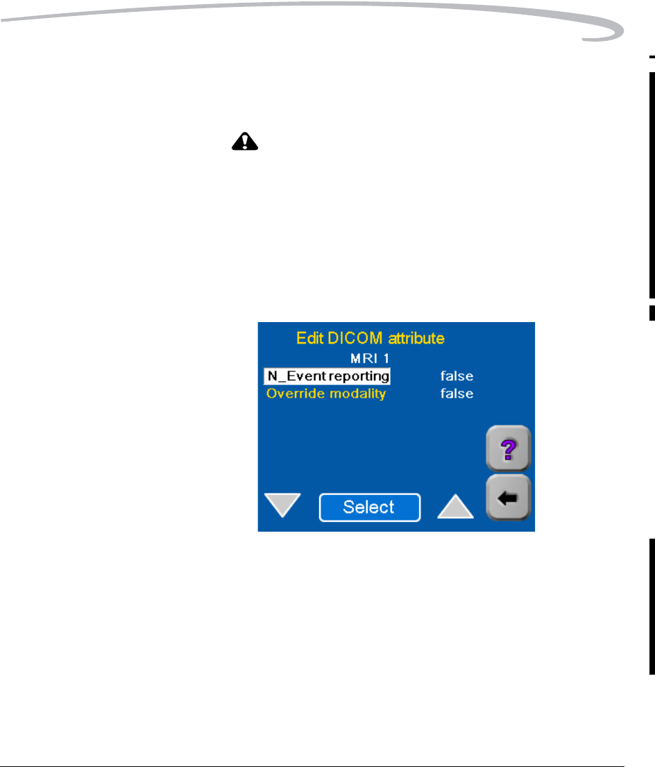
Selecting N_Event
Reporting "N_Events" are status changes at the Imager, such as changes from "ready"
to "busy." The Imager can be configured to report these status changes to
the modality as they changes occur.
CAUTION:
This feature can cause a serious malfunction in the modality
if it is not designed or configured to accept N_Event
messages. Leave the N_Event reporting attribute set to false
unless you are certain the modality can accept N_Event
messages.
1. On the Advanced defaults screen, highlight N_Event reporting.
2. Touch Select to display the Edit DICOM attribute screen.
3. Use the Select button to choose true or false. Selecting true enables
the Imager to send N_Event messages to the modality.
4. For most installations Override modality should be left at false.
NOTE: If you select true for Override modality, the "N_Event
Reporting" value set in step 3 will take precedence over any
request from the modality.
5. Touch the Back arrow to return to the Advanced defaults screen.
4-18 7F3319 September 30, 2004
Adding a Modality
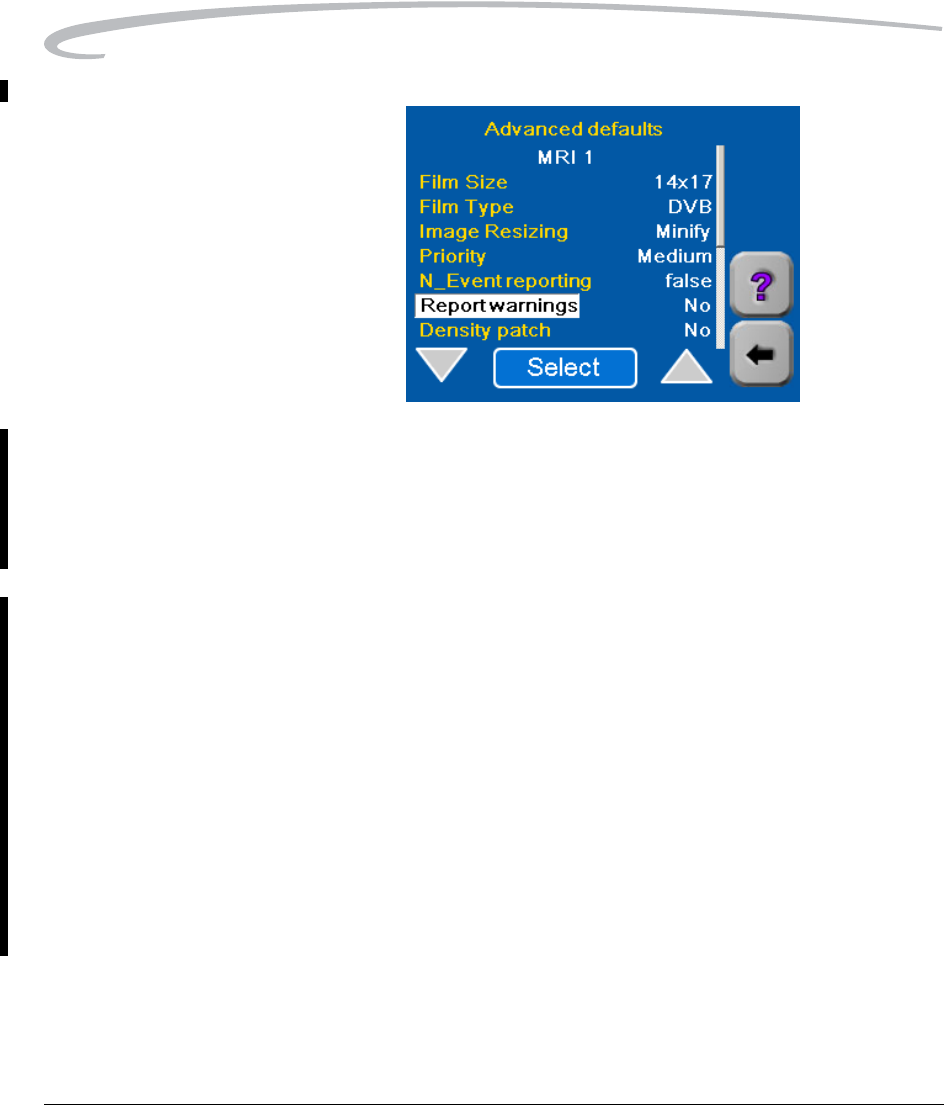
Selecting Report
Warnings "Warnings" are messages from the Imager indicating a non-fatal problem in
the Imager. Like "N_Events," these can be sent to the modality if desired,
but they should not be if they can cause problems at the modality.
1. On the Advanced Defaults screen, highlight Report Warnings.
2. Use the Select button to choose Yes or No.
Selecting Use of a Density
Patch on the Film
A "Density Patch" (also called "dPatch") is a small area of specified density
on the edge of the film that can be used by the Imager software to monitor
and control changes in density from print to print. The Density Patch is used
only on 14 x17 in. film. If the modality requires a different size film, leave
this parameter set to No.
1. On the Advanced Defaults screen, highlight Density patch.
2. Use the Select button to choose Yes or No.
If you select Yes, the Imager will print a Density Patch on the edge of
every print. If you select No, it will not.
When Density Patch is selected, the Automatic Image Quality Control (AIQC)
system in the Imager is enabled. This system monitors image quality
automatically and makes adjustments to minimize sheet-to-sheet density
variation.
Adding a Modality
September 30, 2004 7F3319 4-19
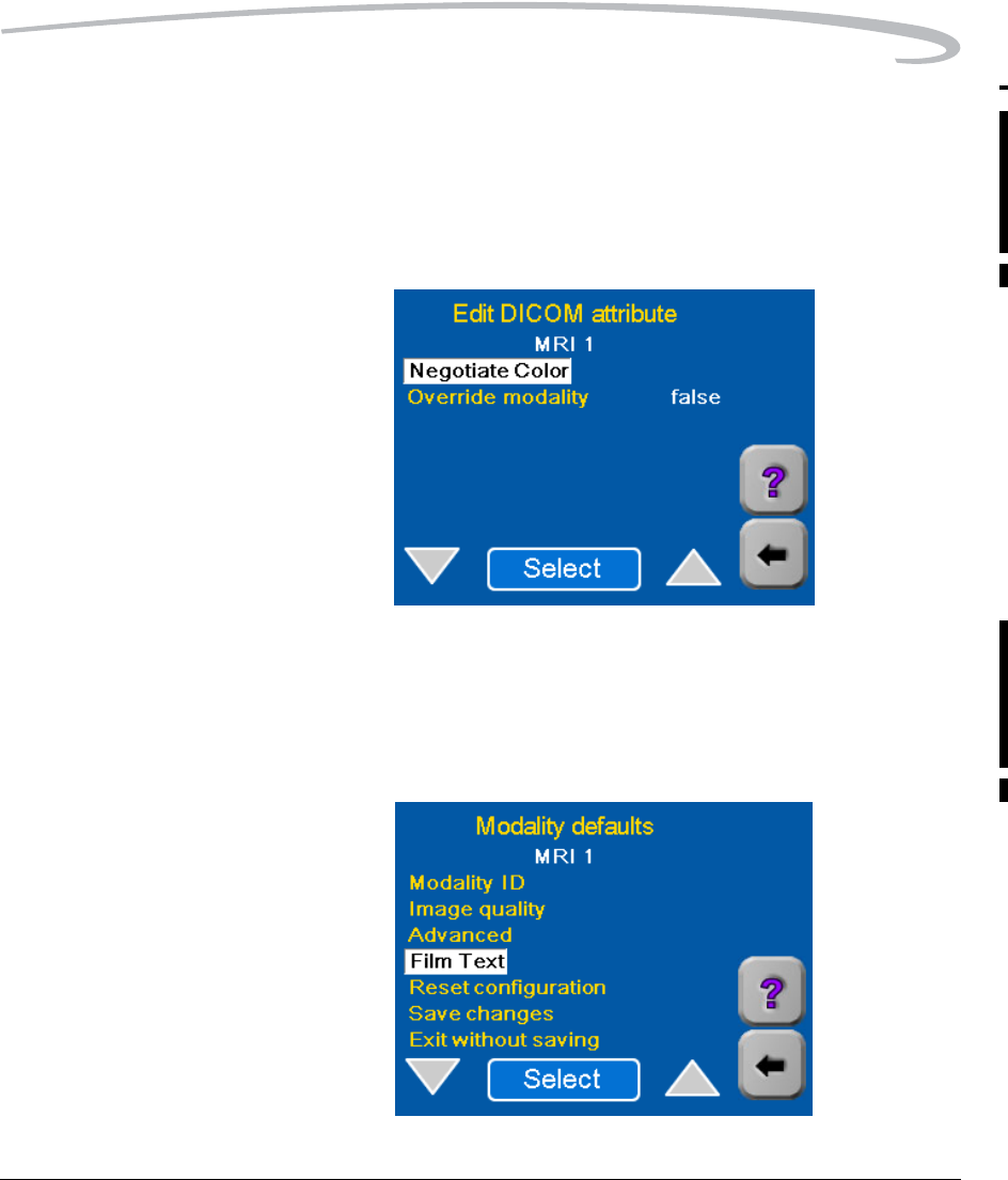
Selecting Color
Negotiation The Imager prints only grayscale images. If a modality has color capability
and a request to print a color image is sent to the Imager, the Imager
software can print a grayscale version of the color image.
1. Touch the Down arrow to proceed to the second Advanced defaults
screen.
2. Use the Select button to choose No.
NOTE: If you select No, the Imager will not accept color prints from the
modality. If you select Yes, it will print a gray scale version of the
color print.
3. Touch the Back arrow to return to the Modality defaults screen.
4-20 7F3319 September 30, 2004
Adding a Modality
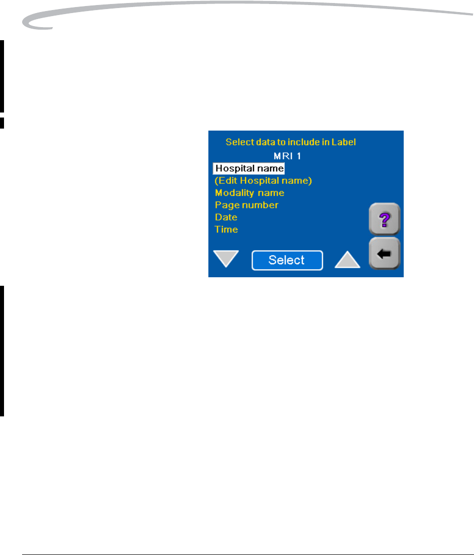
Setting up the Text
(Annotation) Box
This parameter allows you to select items to be printed in a "text box" on
the bottom of each sheet of film.
1. Select Film Text to display the items you can select.
2. Select Hospital name if you wish to include the name of your
hospital in the annotation box. A check will display adjacent to the
field.
a.Select (Edit Hospital name) and touch OK.
b.Use the keypad to enter the name.
c.Touch OK.
3. Select any or all of the other items on the screen. A check will display
adjacent to each item you select.
4. Touch the Back arrow to return to the Modality Defaults screen.
Adding a Modality
September 30, 2004 7F3319 4-21
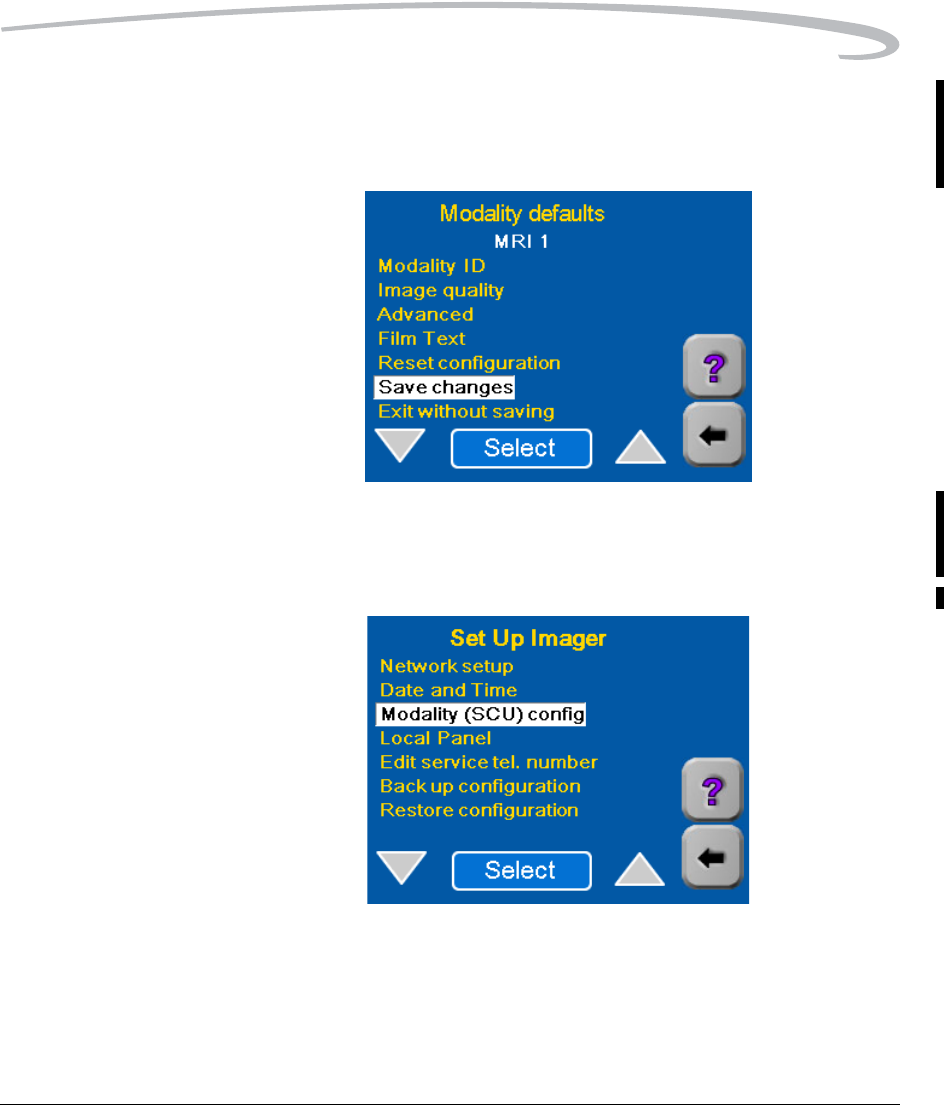
Saving the Modality (SCU)
Parameters
1. Select Save Changes to save the parameter changes you have made.
2. Touch OK.
3. Touch the Back arrow twice to return to the Setup Imager screen.
4-22 7F3319 September 30, 2004
Adding a Modality
Backing up the Configuration
The configuration parameters must be backed up (recorded) on a floppy
diskette so they can be restored if the Imager software is updated.
You will need a blank 3.5-inch floppy diskette, 1.44 mb, IBM format.
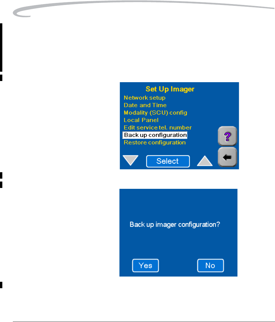
1. Start from the Setup Imager screen.
2. Select Backup Configuration.
3. Touch Yes.
Adding a Modality
September 30, 2004 7F3319 4-23
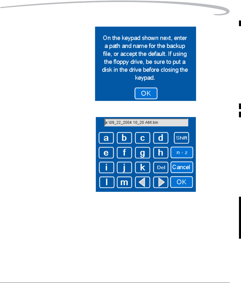
4. Touch OK.
5. Choose an easy-to-remember file name for the backup file. For
example,
a:\09_15_04.bin or a:\backup1.bin. The prefix a:\ and suffix .bin
are required.
6. Write down the filename.
7. Enter the filename on the keypad and touch OK on the keypad.
4-24 7F3319 September 30, 2004
Adding a Modality
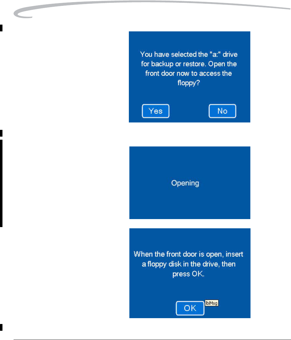
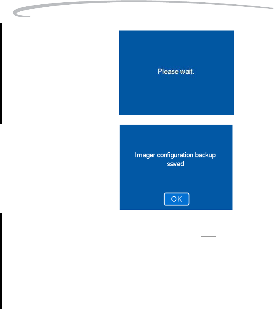
8. Touch Yes.
9. Wait for the front door to open.
Adding a Modality
September 30, 2004 7F3319 4-25
The Imager first closes the film cartridge and then unlatches the door.
This takes about 30 seconds.
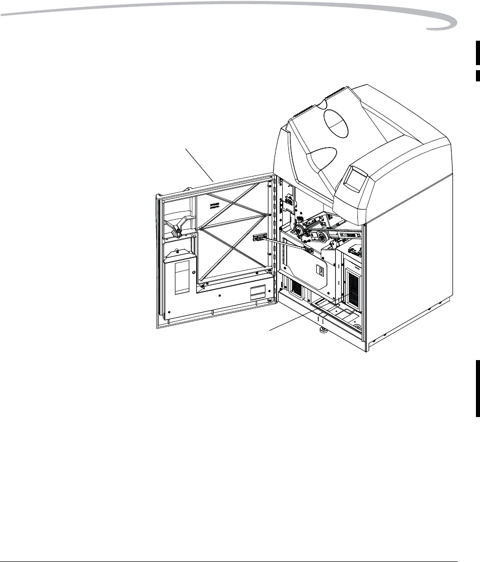
10. Open the computer access door.
11. Insert a blank diskette into the floppy disk drive.
The Imager records a backup file of the configuration parameters on
the diskette.
H200_0034DAA
Front Door
Computer
Access Door
4-26 7F3319 September 30, 2004
Adding a Modality
12. Touch OK.
13. Remove the floppy disk from the computer.
14. On the disk label, write the filename exactly as you entered in step 7.
Include the date of the backup.
15. Store the floppy disk in a safe place. It may be required if the Imager is
serviced.
16. Close the computer access door and the Imager front door.
17. Log out of the Service Passcode:
a.Touch the Back arrow to return to the Main Menu.
b.Touch System Functions.
c.Touch Log off and then Touch OK.

Adding a Modality
September 30, 2004 7F3319 4-27
18. Press the Back arrow.
The Home screen should appear. Configuration of the new
modality is now complete.

Blank Page
September 30, 2004 7F3319 5-1
5
Optimizing Image Quality
Image Quality Parameters
If the quality of an image printed by the Imager is not acceptable, you will
have to enter new values for the parameters shown on the "Image quality"
screen. This section provides basic information that will help you select and
enter values for these parameters that are appropriate to the type of
modality that sent the image.
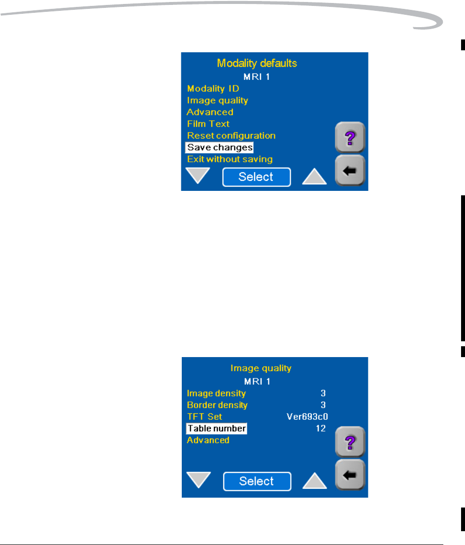
The "Image quality" parameters include:
•Image Density - A setting that determines the maximum density
(Dmax) that will be used in printing.
•Border density - The density of the border of the film.
•TFT Set - A group of 15 Transfer Function Tables (TFTs) used in Kodak
Imagers. Each TFT in the set is a grayscale curve that relates each digital
input (pixel) value to a target value of perceived brightness and a
corresponding target value of printed optical density.
•Table number - A number (1- 15) which specifies a particular TFT
(contrast curve) in the TFT Set selected for printing.
The Advanced Parameters
are "Polarity" and "Smoothing
Type."

5-2 7F3319 September 30, 2004
Optimizing Image Quality
•Advanced - Includes two parameters:
–Polarity - In general, indicates whether an image is black on a
white background or the reverse. In this case, specifies whether the
Imager will print images with the same polarity as the images sent
from the modality (Positive), or the reverse (Negative).
–Smoothing Type - A value (1 - 15) that specifies a level of
smoothness/sharpness in transition between density differences.
Selecting the Image Quality Parameter Values
Use Table 1 (on page 5-4) and Table 2(on page Page 5-8) to select the
image quality parameters. The parameter selections are based on modality
type. They also depend on whether the modality is GSDF-compliant. (GSDF
stands for Grayscale Standard Display Function.)
To select the parameters:
• If the modality is not GSDF-compliant, go to “Non-GSDF Modalities”
below.
• If the modality is GSDF-compliant and does not use PLUTs or uses PLUTs
for only some images, go to “GSDF-Compliant Modalities” on page 5-9.
(PLUT stands for Presentation Look-Up Table.)
• If the modality is GSDF-compliant and uses PLUTs for all images, it is not
necessary to change the image quality values in the Imager. Continue
with “Setting the Advanced Parameters” on page 4-11.
Non-GSDF Modalities Use this procedure to select parameters for modalities that are not GSDF-
Compliant.
Write down the parameter values you select.
1. Refer to Table 1 and find the Modality Type for which the Imager is
being configured.
2. Choose the TFT Set recommended in the table for this type of
modality. If more than one TFT Set is listed, read the Notes in the table
for guidance in selecting the appropriate set.
3. Choose the Table No. (contrast setting) recommended for the chosen
TFT Set. If a number is in boldface type, choose this number first. (You
may have to try more than one Table Number.)

Optimizing Image Quality
September 30, 2004 7F3319 5-3
4. Choose the Image Density associated with the Table No. you chose.
If there is a range of density values:
• Choose the density value indicated in bold if there is one.
• If there is no bold value, choose the middle value. For example, if
the range is 2.7 to 3.1, choose 2.9.
• If there are only 2 density values, choose either one.
5. Choose the Smoothing Type from Table 1.
6. For Border Density on the film, choose a low density for a clear
border and a high density for a black border. Typically this density is
matched to the Image Density. (This parameter is not included in
Table 1.)
7. For Polarity of the film, choose either Positive or Negative. Positive is
used for most applications. Negative is used by Nuclear Medicine
modalities. (This parameter is not included in Table 1.)
8. Continue with “Entering the Image Quality Parameters” on page 5-10.

5-4 7F3319 September 30, 2004
Optimizing Image Quality
Table 1. Selection of Parameters by Modality Type
Modality Type TFT Set Table No.
(Contrast
Setting)*
Image
Density
(Dmax)*
Smooth-
ing Type
Note
Kodak and other CR
(Computed Radiography)
and DR (Digital
Radiography) Systems.
Also Workstations and
imaging devices that output
data to a linear-in- density
contrast curve.
WRKSTN2A.w87 1
2
3
4
3.1
3.0
2.9
2.8
5Select Table number
(contrast) and Dmax in
the pairs shown.
Do not use with Fuji
CR.(See Fuji CR below.)
Fuji CR FCR302C4.w87 10
11
12
13
14
15
2.6
2.7
2.8
2.9
3.0
3.1
5Table number
(contrast) and Dmax
must be chosen in the
pairs shown. The
contrast curves are
approximately linear in
density for most of the
pixel value range, but
become relatively flat at
high (bright) pixel
values. Designed for use
with Fuji CR only.
CT (Computed
Tomography) or MRI
(Magnetic Resonance)
VER693C0.w87 5, 7, 8 3.0, 3.1 15 Table 7 provides good
grayscale range in all CT
and MRI studies. Table 5
has less mid-tone
contrast. Table 8 has
more mid-tone contrast.

Optimizing Image Quality
September 30, 2004 7F3319 5-5
DSA (Digital Subtraction
Radiography), including
C-Arm and Digital Fluoro
VER713C0.w87
(Alternative 1)
6, 7, 9 2.9 - 3.1 15 VER713C0 provides
brighter image
background than
VER693C0. Lower Table
numbers have less
mid-tone contrast.
Higher have more.
VER693C0.w87
(Alternative 2)
6, 7, 9 2.9 - 3.1 15 VER693C0 provides
darker image
background than
VER713C0. Lower Table
numbers have less
mid-tone contrast.
Higher have more.
Phillips Medical Systems
(PMS) -
EasyVision and other PMS
modalities.
PMSV3K.w87 9 3.0, 3.1 15 Check with the PMS
service engineer. On
some PMS modalities,
image quality
calibration must be run
from the PMS control
console.
Table 1. Selection of Parameters by Modality Type
Modality Type TFT Set Table No.
(Contrast
Setting)*
Image
Density
(Dmax)*
Smooth-
ing Type
Note

5-6 7F3319 September 30, 2004
Optimizing Image Quality
Nuclear Medicine VER713C0.w87
(Alternative 1)
5 - 7 - 10 2.2, 2.3 12 Table 7 is popular.
Table 5 has less
mid-tone contrast and
shows more isotope
takeup. Table 10 has
more mid-tone contrast
and reduces takeup
visibility on film.
PMSV3K.w87
(Alternative 2)
10 - 14 2.2, 2.3 12 Start with Table 10.
Higher tables have
increased brightness
and reduce isotope
takeup visibility on film.
Lower tables show more
takeup.
Siemens Host Control or
Workstation
WRKSTN2A.w87 42.815
Typically the density is
set to 2.8 by the Siemens
host control software.
Table 4 must be chosen
for linear grayscale
translation.
Table 1. Selection of Parameters by Modality Type
Modality Type TFT Set Table No.
(Contrast
Setting)*
Image
Density
(Dmax)*
Smooth-
ing Type
Note

Optimizing Image Quality
September 30, 2004 7F3319 5-7
Ultrasound VER693C0.w87
(Alternative 1)
5 - 8 - 12 2.4 - 2.8 15 Table number choices
vary with manufacturer
and radiologist. Lower
table numbers have less
mid-tone contrast.
Higher numbers have
more.
PMSV3K.w87
(Alternative 2)
7 - 10 - 13 2.4 - 2.8 15 Table number choices
vary with manufacturer
and radiologist. Higher
table numbers have
increased brightness.
Notes: * The number in bold should be the first choice when you are selecting parameter values.
Table 1. Selection of Parameters by Modality Type
Modality Type TFT Set Table No.
(Contrast
Setting)*
Image
Density
(Dmax)*
Smooth-
ing Type
Note

5-8 7F3319 September 30, 2004
Optimizing Image Quality
NOTE: Some DICOM GSDF-modalities may direct the use of DICOM
Presentation Look Up Tables (PLUTs) for some or all images. If the
PLUT capability in the 8150 Imager is enabled, a PLUT sent from
the modality overrides the GSDF0 TFT set (used for GSDF
modalities) and associated parameter settings. The DICOM PLUT
capability in the Imager is normally enabled but can be disabled by
your Service Provider.
Table 2. GSDF0 Dmax Setting versus
Table Number (Contrast Setting)
Density (Dmax) Table Number
(Contrast)
1.7 1
1.8 2
1.9 3
2.0 4
2.1 5
2.2 6
2.3 7
2.4 8
2.5 9
2.6 10
2.7 11
2.8 12
2.9 13
3.0 14
3.1 15
Density and Table Number must be chosen in the pairs
shown.

Optimizing Image Quality
September 30, 2004 7F3319 5-9
GSDF-Compliant
Modalities Use this procedure to select image quality parameters for GSDF-Compliant
modalities that do not use PLUTs or use PLUTs for only some images.
Write down the parameter values you select.
a. Choose TFT Set GSDF0.w87 (used for all GSDF modalities).
b. Refer to Table 1 (on page 5-4) and find the Modality Type for which
the Imager is being configured.
c. Choose Image Density. Choose the recommended density value in the
Image Density column. If there is more than one density value:
• Choose the bold value if there is one.
• If there is a range of values (but no bold value), choose the middle
value.
• If there are only 2 values, choose either value.
d. Refer to Table 2 (on page 5-8). Choose the Table Number that
corresponds to the Image Density value you selected.
e. Choose the Smoothing Type for the modality type from Table 1.
f. For Border Density on the film, choose a low density for a clear border
and a high density for a black border. Typically this density is matched to
the Image Density. (This parameter is not included in Table 1.)
g. For Polarity of the film, choose either Positive or Negative. Positive is
used for most applications. Negative is used by Nuclear Medicine
modalities. (This parameter is not included in Table 1.)
h. Continue with “Entering the Image Quality Parameters” on page 5-10.
5-10 7F3319 September 30, 2004
Optimizing Image Quality
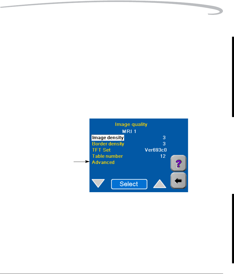
Entering the Image Quality Parameters
1. After choosing the parameter values for the modality, enter them from
the Image quality screen.
• Each choice on this screen calls up an entry screen for one of the
parameters.
• On some parameter entry screens an Override Modality option
appears. The choices are True or False. For most installations you
should select False.
If you select False, the parameter value you enter will be used only
if the modality does not send this parameter with a print job.
NOTE: Select Advanced to enter Smoothing Type and Polarity.
2. Touch the Back arrow (2 or 3 times) to return to the Modality
defaults screen.
Optimizing Image Quality
September 30, 2004 7F3319 5-11
3. Select Save changes to save the changes you have made, and touch
OK.
4. Send another image from the modality and check print quality.
NOTE: For DICOM GSDF-compliant modalities, the printed images should
approximately match images on DICOM GSDF-compliant displays.
5. Is the quality of the print acceptable?
• Yes: Continue with“Setting the Advanced Parameters” on
page 4-11.
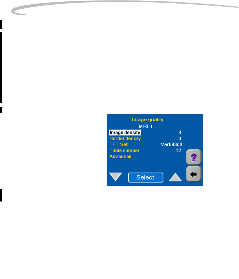
• No: Select Image Quality.
6. If an "Image Quality Help" screen appears, touch X.
7. Refer again to Table 1 (Table 2 for GSDF-compliant modalities) and
choose the Table No. (for the same modality type) that is just below or

5-12 7F3319 September 30, 2004
Optimizing Image Quality
above the one you previously entered.
8. Enter and save the new Table number (steps 1 - 3).
9. Send another image from the modality and check print quality again.
NOTE: You may have to try other Table numbers (and Densities) to
achieve high quality prints.
10. When print quality is acceptable, return to “Changing the Modality ID”
on page 4-10.
11. If you are unable to achieve satisfactory quality, call service for help.
Refer to “Calling for Support” on page 3-17.

September 30, 2004 7F3319 6-1
6
Specifications
Dimensions
Electrical
Height: 117 cm (46 in.) - Top cover closed
158 cm (62.3 in.) - Top cover open
Width: 63.5 cm (25 in.)
Depth: 66 cm (26 in.) - Front door closed
124.5 cm (49 in.) - Front door open
Weight: 204 kg (450 lb)
Voltage: 100 V ±10%, 50/60 Hz ±3 Hz
120 V ±10%, 50/60 Hz ±3 Hz
230 V ±10%, 50/60 Hz ±3 Hz
Current Draw: 100 V: 12 Amps max.
120 V: 10 Amps max.
230 V: 5.3 Amps max.
Power Consumption: 1200 W (maximum)

6-2 7F3319 September 30, 2004
Specifications
Laser Specifications
Operating Environment
Storage Environment
Environmental Effects
Wavelength: 805 - 815 nm
Power: 50 mW
Type Diode
Diode Radiation Class: 3B
Imager Radiation Class Class 1 product
Temperature: 15° to 35° C (59° to 95° F)
Humidity: 15% to 85% RH, non condensing
Magnetic Field: < 50 Gauss
Altitude 3048 - 12,192 m (100 - 40, 000 feet)
Temperature: -35° C to 60° C (-31° F to 140° F)
Humidity: 10% to 90% RH, non condensing
Altitude Up to 3048 m (10,000 feet)
Heat Dissipation: 3000 BTU/hour (average)
Acoustical Noise: Less than 55 dB at one meter (70 dB
momentary)
Less than 80 dB, non-repetitive tasks
such as door open/close

Specifications
September 30, 2004 7F3319 6-3
Film Sizes
The 8150 Laser Imager processes the following film sizes:
•28 x 35 cm DryView Film (11 x 14 in. landscape)
•35 x 35 cm DryView Film (14 x 14 in.)
•35 x 43 cm DryView Film (14 x 17 in.)
Film Types
The 8150 Laser Imager processes the following film types:
•Kodak DryView DVB Laser Imaging Film
•Kodak DryView DVC Laser Imaging Film
•Kodak DryView DVB+ Laser Imaging Film
•Kodak DryView DVB+ Premium Laser Imaging Film
NOTE: Not all of these film types are available in every country.
Film Throughput
Prints 70 films per hour.
Agency Compliance
See the Kodak DryView 8150 Laser Imager Safety Manual, document
number 7F3779.
Blank Page

September 30, 2004 7F3319 7-1
7
Film Technical Information
General Description
This section describes the characteristics of Kodak DryView Laser Imaging
Film, not the operation of the Kodak DryView 8150 Laser Imager. DryView
Laser Imaging Film is a high-resolution, infrared-sensitive,
photothermographic film designed specifically for the family of Kodak
DryView Laser Imagers. DryView Laser Imaging Film is packaged in
daylight load packages, available in blue or clear, 7-mil polyester base.
The 8150 Laser Imager accepts three film sizes:
• (28 x 35 cm) 11 x 14 in.
• (35 x 35 cm) 14 x 14 in.
• (35 x 43 cm) 14 x 17 in.
Spectral Sensitivity DryView Laser Imaging Film is infrared sensitive and has been sensitized to
the infrared laser diode of DryView Laser Imagers. When handled
according to instructions on the daylight-load film package, safelights are
not needed. If you remove undeveloped film from the daylight load
package, you will need a darkroom setting and a green safelight.
7-2 7F3319 September 30, 2004
Film Technical Information
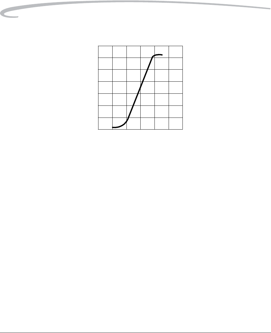
Relative Log Exposure (Example)
Image Quality DryView Laser Imaging Film delivers diagnostic-quality, continuous-tone
images along with sharp alphanumerics and optimum contrast. This
high-quality, silver-based film provides radiologists with the same diagnostic
information they are accustomed to viewing - including the spatial
resolution, contrast and grey levels. Because it is a totally dry imaging
process, there is no image quality variability due to “wet” chemistry.
Automatic Image Quality
Control DryView Laser Imaging Film is system-matched for the Kodak patented
Automatic Image Quality Control (AIQC) technology. This fully automated
system, which is a standard feature of DryView Laser Imagers, is designed
to ensure that image quality parameters meet preset user preferences,
film-to-film, lot-to-lot.
Environmental Impact Tests show that DryView Laser Imaging Film is not considered hazardous to
the environment. As a result, you can develop, recycle, and dispose of film
with less impact on the environment than if you were using wet-developed
silver halide films.
Sensitometric Characteristics
RELATIVE LOG EXPOSURE
0 0.5 1 1.5 2 2.5 3
0
0.5
1
1.5
2
2.5
3
3.5
DENSITY
H188_1072AC

Film Technical Information
September 30, 2004 7F3319 7-3
Recycling Film According to the Environmental Protection Agency (EPA) standards,
DryView Laser Imaging Film is not considered hazardous and requires no
special disposal procedures. However, the film does contain silver and
polyester that may be recovered by using one of several recycling processes.
Call your local Kodak sales representative or go to the Kodak web site
www.kodak.com/go/KES
Refer to Publication J700 and see “End of Life Management' section.
Storing and Handling
Undeveloped Film
To achieve consistent results up to the expiration date indicated on the film
package, DryView Laser Imaging Film must be stored in a cool, dry place
(41° F/5° C to 77° F/25° C) and protected from radiation and chemistry
fumes.
The film can withstand short-term temperature spikes (up to 95° F/35° C)
for several hours during transit without any significant effect on film quality
or performance. Transit temperatures above 95° F/35° C will gradually
diminish shelf life. If the AIQC encounters film that has been damaged by
improper handling, the AIQC will automatically alert system operators.
DryView Laser Imaging Film - US Environmental Regulations Comparison
Wet Silver Halide DryView
Developer Fixer Wash Film Film
Product Regulations
OSHA MSDS Required Required Not required Not required Provided
DOT Hazardous Hazardous No limits No limits No limits
Use permits Local Local None None None
Disposal* Regulations
EPA Hazardous Hazardous No No No
DOT Hazardous Hazardous No No No
Note: There is no SUPERFUND liability with DryView Laser Imaging Film.
* State and local laws vary. Consult appropriate regulations or authorities prior to disposal.

7-4 7F3319 September 30, 2004
Film Technical Information
Handling Developed Film Handling DryView Laser Imaging Film requires reasonable care.
Prolonged exposure to intense light or excessive heat (130° F/54.4° C) for
more than 3 hours may cause some gradual darkening of images. Leaving
films in vehicles in hot climates for extended periods of time is not
recommended.
Spills, humidity and other forms of water typically have no significant effect
on image quality or film integrity. If necessary, film can be cleaned with a
clean, damp cloth.
For best results, store film in sleeves when not being reviewed. DryView
Laser Imaging Film can be left on a light box for more than 24 hours. In
extreme cases in which light boxes are exceptionally hot (120° F/49° C),
Kodak recommends removing them prior to 8 hours of continuous
exposure.
Take care when using spotlight viewing for more than 30 seconds because
temperatures near the light source may exceed 180° F/82.2° C. Use in slide
projectors is not recommended due to the high temperatures generally
found in these devices.
With DryView technology, a small amount of final development occurs
when the film exits the Laser Imager and is initially exposed to ambient or
view-box lighting. This is virtually undetectable and has no effect on image
quality (i.e., typically 0.02 change in density). This small density increase is
uniform and permanent upon full exposure of the film under normal
handling conditions (i.e., room light or view box).
Archiving Developed Film DryView Laser Imaging Film has been tested and can be archived for more
than 100 years when stored at American National Standards Institute (ANSI)
recommended storage conditions (77° F/25° C). Developed films may be
stored at higher temperatures; however, that may reduce the number of
years the film can be stored. For example, storing films at a constant
elevated temperature of 90° F/32.2° C may reduce archive capability to 30
years.
Dissipating Odor DryView technology eliminates virtually all unpleasant odors. While some
low-level odors are produced during the development process, they pose
no known adverse health risks. Processing odor levels are further reduced
by a non-hazardous, recyclable filter in the Laser Imager. This filter traps
most low-level odors and prevents them from dissipating into the work

Film Technical Information
September 30, 2004 7F3319 7-5
environment. To help maintain optimum performance, the filter requires
periodic replacement. DryView Laser Imagers require no special venting.
Dissipating Heat DryView Laser Imagers use controlled heat to develop DryView Laser
Imaging Film. The heat has virtually no effect on the air temperature of the
work area. The amount of heat dissipated into an area during a day is
typically less than the heat generated by four 100-watt light bulbs.
Blank Page

September 30, 2004 7F3319 Glossary-1
Glossary
AIQC Automatic Image Quality Control.
CR Computed Radiography, the process of creating digital radiographic images.
CT Computed Tomography, the process of creating digital tomographic images.
DICOM Digital Imaging and Communications in Medicine. A TCP/IP-based protocol
for transmitting and receiving medical imaging and related data over a
network.
Dmax Maximum density. The density of an area on the film which has received
maximum exposure.
Dmin Minimum density. The density of an unexposed area on the film.
Dpatch Density patch. A small patch of specified density on the trailing edge of each
film that AIQC uses to monitor density change on film.
DR Digital radiography, the process of creating digital radiographic images.
DVB DryView Blue Laser Imaging Film.
DVC DryView Clear Laser Imaging Film.
GSDF Grayscale Standard Display Function
Key operator The person(s) designated by the department manager to receive
applications training and allowed access to password-protected areas to
make system changes.
Modality Medical equipment that actually generates medical images (for example, an
MRI).
MR Magnetic Resonance.
N/A Not available or not applicable.
K number The K number (Kodak number) is located on the Local Panel System
Information Screen.
Platen The metal surface on which the film rests as it is exposed.
Shutdown The process of exiting current tasks and applications and turning the power
off.
SMPTE test pattern A Society of Motion Picture and Television Engineering monitor test pattern
that is used for analyzing image-quality problems.

Glossary-2 7F3319 September 30, 2004
Test type The type of test film that will be printed. Two film test types are available: a
density test film (SMPTE pattern) and a calibration film.
TFT Transfer Function Tables.
Unprintable queue The queue of jobs that cannot be printed because of errors in the print jobs.

Eastman Kodak Company
343 State Street
Rochester, NY 14650
Kodak and DryView are trademarks of Eastman Kodak Company.
© Eastman Kodak Company, 2004