Eaton HHB1WSOC Monitoring Device User Manual Manual
Eaton Corporation Monitoring Device Manual
Eaton >
Manual

Water Shut-off
Controller
User’s Guide

2

3
Contents
Introduction ........................................................ 4
1. Water Shut-Off Controller Uses ...... ... ... ... ... ... ... 4
Water Shut-Off Controller Components ........................ 5
Getting Started ..................................................... 6
Installing the Water Shut-Off Controller ....................... 7
1. Prepare ..................................................... 8
2. Place ....................................................... 9
3. Set Up .....................................................11
4. Test ........................................................ 17
5. Choose Sensor Controllers .. ... ... ... ... ... ... ... ... .. 19
6. Use ......................................................... 22
Compliance Information .........................................27

4
Introduction
The Home Heartbeat Water Shut-Off Controller is designed
to help you manage the flow of water into your home.
You can use any Home Heartbeat sensor as a “controller”
in combination with the Water Shut-Off Controller. For
example, when used with Water Sensors, the system can
be set to automatically shut off the water to your home in
the event of a burst pipe or appliance leak. Or, you can add
an Attention Sensor to shut off your main line with the press
of a button. Your Home Key can be used to open and close
the valve, or you can choose to operate the unit manually.
This Guide will introduce you to Water Shut-Off Controller
and assist you with setup and use.
Water Shut-Off
Controller Uses
To shut off water in response
to leaks from home appliances
and products connected to main
water lines, such as:
• Washing machines
• Toilets
• Refrigerator automatic
ice-makers
• Kitchen, bath or laundry
room sinks
Great for use in:
• Family Home
• Vacation Home
• Rental Properties
5
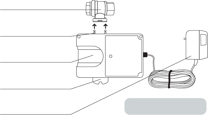
Water Shut-Off Controller Components
Home Heartbeat
Brass Ball Valve
(not included)
Pegs & Clip
Use the clip to attach the ball valve
to the pegs on the unit.
Slide Channel
Slide the Home Key here to add the
unit to the system
Valve Handle
Use the handle to open and close the
ball valve when unit is unplugged.
Power Adapter
Plug the adapter into a wall outlet—
do not use an extension cord.
WARNING: Do not remove the ferrite
on the power supply cable.

6
Getting Started
Before installing the Water Shut-Off Controller,
please note the following:
The product is for:
• Indoor use only.
• Use with cold water lines only.
The use of this product requires the installation of:
• The HomeHeartbeat Starter Pack.
• At least one Home Heartbeat Sensor, which acts as a
controller to trigger an alert and close the Water Shut-Off
Controller (Eaton recommends Water Sensors and Attention
Sensors).
• A Home Heartbeat Brass Ball Valve (not included), through
which the Water Shut-Off Controller is connected to the main
water line. The ball valve must be pre-installed at least 18”
downstream from a water meter and within 8 feet of a power
outlet.
WARNING: Do not put fingers
inside the ball valve, as it
can close with a force strong
enough to sever them.

7
Installing the Water Shut-Off
Controller
Follow these steps to install the Water Shut-Off Controller:
1. Place the Water Shut-Off Controller by joining it to the
brass ball valve that was installed on your main water
line.
2. Set up the Water Shut-Off Controller using the Home
Key.
3. Test that the system is working.
4. Choose sensor controllers that, on alert, will
communicate with the Water Shut-Off Controller to
shut off the water to your home.
5. Use the product—get alerts, and open and
shut the valve.
8
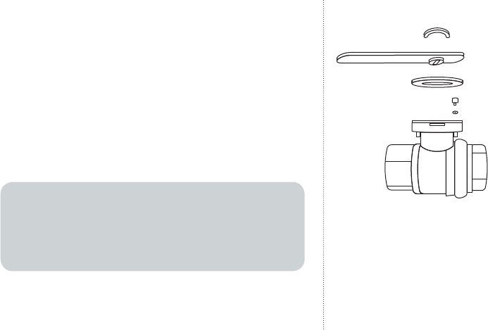
1. Prepare
Prepare the ball valve by following the following four
steps:
• REMOVE retaining ring
• REMOVE valve handle
• REMOVE plastic washer
• REMOVE screw and nut
NOTE
Valve handle may be difficult to slide off.
TIP: try sliding a flat head screwdriver between the handle and
the valve to help pry it loose.
9
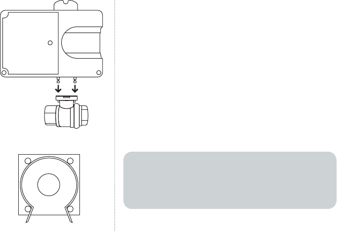
2. Place
JOIN the Water Shut-Off Controller to the ball valve by lining
up the pegs on the Water Shut-Off Controller to the holes on
the brass ball valve.
Make sure the Slide Channel is facing you. The long side
of the Water Shut-Off Controller should be parallel to the
water pipe.
ATTACH the horseshoe clip to hold the Water Shut-off
Controller in place. When doing so, make sure that the clip
rests on the inside of the pegs as shown in the bottom left
hand corner of this page.
WARNING
To reduce risk of electrical shock, fire or damage to property
or device:
• DO NOT use extension cord.

10
CAUTION
To reduce the risk of pinching your fingers, keep your hands
away from the water shut-off controller when you connect
the power.
PLUG IN the Water Shut-Off Controller to a nearby outlet.
DO NOT use an extension cord. You will hear the Water
Shut-Off Controller rotate the ball valve 180 degrees. The
green LED light will blink while the unit checks its position.*
Wait for it to stop blinking before moving to Step 2.
*Each time the Water Shut-Off Controller is first turned on (for example,
during installation or after a power outage), it rotates the ball valve 180
degrees to check its position.
11
3. Set up
CARRY the Water Shut-Off Controller, your Home Key, a
spare water sensor and a small glass of tap water to where
the brass ball valve is installed in your home. (If all of your
water sensors are in place, use a nearby water sensor.)
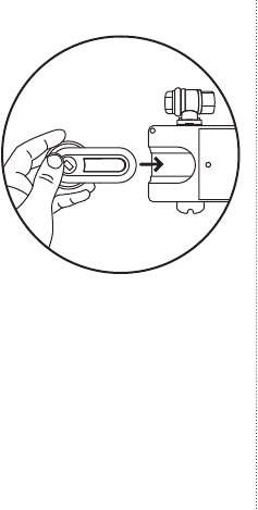
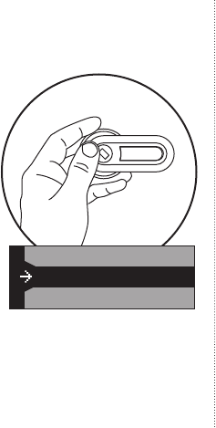
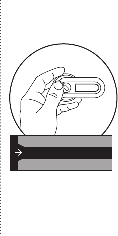
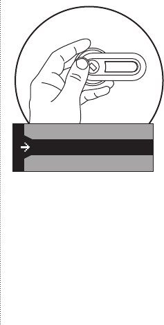
CLICK the Home Key thumbwheel to wake the screen, and
SLIDE the Home Key into the Slide Channel.
The Home Key should say:
Please wait…
Device found
OK to remove key
Slide the Home Key
into the Slide Channel
12
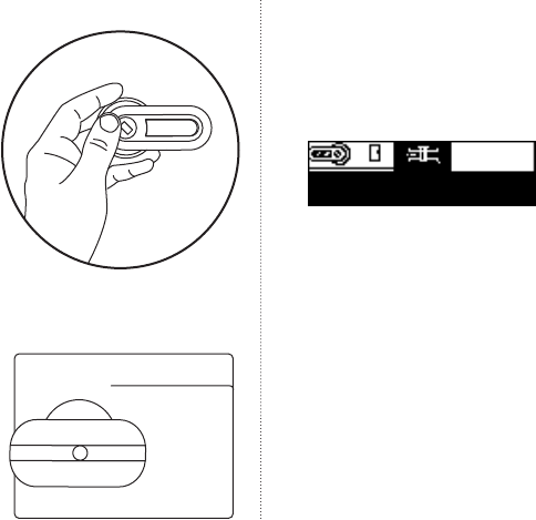
If you slide the Home Key into the Slide Channel and the
Home Key screen shows either of the following messages,
the Home Key or Water Shut-Off Controller may be outside
the range of the Base Station.
If you see either of these messages, you should add a Home
Heartbeat Range Extender between the Base Station and
Water Shut-Off Controller. This addition will expand the
transmission zone of the Base Station to the Controller.
Then, you can repeat Step 2.
J]egn]C]q&&&
Hd]Yk]ljqY_Yaf
K]fkgjgmlg^jYf_]7
J]egn]C]q&&&
;Yflk]lmhfgo
C]qgmlg^jYf_]
13
The Home Key will now bring you through a setup wizard
to name it, choose sensor controllers, and set In-Home
Awareness and “CallMe” Awareness:
1. First, you will NAME the Water Shut-Off Controller.
CLICK Choose Name and roll the thumbwheel to
highlight your selection. CLICK once to set the name.
2. Change Valve State? is the next step in
the wizard. CLICK once to see the following choices:
Closed, Open, and Don’t Change. The current
state will be highlighted. Though you do not need to
make a choice at this time, try choosing the opposite
state (open or closed) to see how it works. You should
hear the unit changing the position of the ball valve. So
that you can test the system later, set it to Open before
moving to the next step in the wizard. You can always
change it afterward.
Open
Closed
Don’t Change
14
3. CLICK on Pick Controllers. Highlight and
CLICK on the name for the spare water sensor you
brought with you or the nearby water sensor you are
using for testing. The box next to the sensor name will
show a check. You can pick multiple sensors to act as
Controllers. To complete this step, highlight and CLICK
Done, Go back.
If you cannot see the sensor controller you want in the
list on Home Key, please see the Note below. *
4. Set In-Home Awareness to choose if you’d like
to get alerts on the Home Key when you are at home and
in range of the Base Station. So that you can test the
system later, CLICK on Alarm on Closed. You can
always change it afterward.
In-Home Awareness
Pick Controllers
“Call Me” Awareness

15
5. Set “CallMe” Awareness to choose if you’d
like to receive alerts about the Water Shut-Off Controller
through your cell phone or email.** CLICK to select one
of the following options: ”Don’t call me”, “Call me on
Closed”, “Call me on Open”, or “Call me on Changing”.
6. After all of these options are set, the screen will
automatically highlight “Done, go back?” CLICK once to
finish setting up the Water Shut-Off Controller.
* Note: If you cannot see the sensor controller you want
on your Home Key, it means that the sensor is not set for
in-home alerts or “CallMe” Awareness. You can
check the setting for that sensor after moving through the
setup wizard. For now, choose one and allow the Home
Key to bring you through the next options, In-Home
Awareness and “CallMe” Awareness. After
you’ve completed setup, use your Home Key, highlight the
icon you’d like to use as a controller, and DOUBLE-CLICK.
Make sure that:

16
1. The controller is in range of the Base Station.
2. It is set to “Alarm on ___” under the In-Home
Awareness setting, and/or is set to “Call me on ___”
under the “CallMe” Awareness setting.
If you choose a sensor as a controller and later
change its In-Home Awareness setting to “Don’t alert”
and/or its “CallMe” Awareness setting to “Don’t call
me”, it will be automatically removed as a sensor
controller under the Water Shut-Off Controller menu
called “Pick controllers?”
** In addition to setting sensor and Global
“CallMe” options on the Home Key, you must register
with Home Heartbeat Support (1-800-813-2199 or
www.homeheartbeat.com) to get remote alerts.
17
4. Test
To test general operation:
1. Using the Home Key, ROLLOVER and highlight the Water
Shut-Off Controller icon.
2. DOUBLE CLICK the thumbwheel, highlight and CLICK
Change Valve State, and highlight and CLICK
Closed. If it was open, you should hear the motor
close the ball valve and see the Valve Handle rotate 90
degrees.
3. Once again, ROLLOVER and highlight the Water Shut-Off
Controller icon On the Home Key. DOUBLE CLICK the
thumbwheel, highlight and CLICK Change Valve
State, and highlight and CLICK Open. The ball valve
will open.
Water Shut-Off Controller
OPEN
Rotate to Close
18
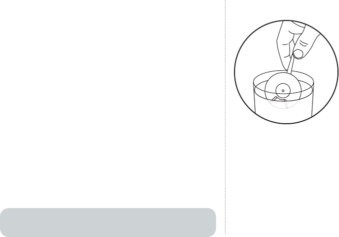
To test the automatic shutoff feature:
1. Dip the Controller’s water disc into the tap water. You
should hear the valve close and see the Valve Handle
rotate 90 degrees to shut off the water.* Check the Home
Key screen for feedback.
3. Once again, ROLLOVER and highlight the Water Shut-Off
Controller icon On the Home Key. DOUBLE CLICK the
thumbwheel, highlight and CLICK Change Valve
State, and highlight and CLICK Open. The ball valve
will open.
3. ROLL OVER and highlight the Water Shutoff Valve
Controller icon on the Home Key.
4. DOUBLE CLICK the thumbwheel, highlight and CLICK
Change Valve State, and highlight and CLICK
Open.
* Water that is free of minerals or sediment, such as bottled
or distilled water, will not activate the water sensor.

19
5. Choose sensor controllers
Now that you’ve installed and tested the Water Shut-Off
Controller, you can consider the types of situations when
you’d want it to close its valve and shut off the water to
your home. During this step, you can choose one or several
Home Heartbeat Sensors to use as controllers.
The Water Sensor works well as a controller because it
can sense the presence of water and, when set to “Alarm
on Wet”, will communicate back to the Water Shut-Off
Controller to shut its valve. It can be placed below washing
machine, toilet, or sink hookups to help reduce damage if
they burst from aged or faulty pipes or seals.
In addition to your Home Key, the Attention Sensor can be
used as a controller to shut the Water Shut-Off Controller
valve from a convenient location, such as your kitchen.
For example, you may want to shut off the main water to
your vacation home before leaving. If you set the Attention
sensor to alarm in the In-Home Awareness setting and
press the front of it, it will shut the valve. The LED on the

20
front of the Attention Sensor will light up when the alert is
sent, and will continue to blink to remind you that you shut
off the valve. To open the valve again, please see “Opening
and closing the ball valve” in Part 5, Use.
Once you have decided on the sensors you want to use as
controllers, follow these steps to set them up:
1. REVIEW each sensor that you want to be a controller.
Make sure they are all set to alarm. Sensors that are
not set to alarm will not appear on your Home Key and
cannot be used.
2. ROLL OVER the Water Shut-Off Controller icon on your
Home Key.
3. DOUBLE CLICK the thumbwheel, highlight and CLICK on
Pick Controllers.
If you cannot see a controller in the list, scroll to
Done, Go back and CLICK once to exit from the
Water Shut-Off Controller menu. Now, highlight and

21
DOUBLE-CLICK on the icon you would like to use as a
controller. Make sure that:
a. The controller is in range of the Base Station.
b. It is set to Alarm on ___ under the In-Home
Awareness setting, and/or is set to Call me on
___ under the “CallMe” Awareness setting
4. Highlight the name and CLICK the thumb wheel to select
each device you want to use as a controller. When you
have finished, highlight and CLICK on Done, go
back?
Note: If you choose a sensor as a controller and later
change its In-Home Awareness setting to Don’t alert
and/or its “CallMe” Awareness setting to Don’t
call me, it will be automatically removed as a sensor
controller under the Water Shut-Off Controller menu called
Pick controllers?

22
6. Use
Getting alerts
After correct setup, the Water Shut-Off Controller will
shut off the main water to your home if any or all of the
controllers send an alert. If a controller alerts, you will
see a full-screen alert flashing red on the Home Key or
receive an alert on your cell phone or through email,
depending on how you’ve set up the system.
If the system fails to send an alert
There are two cases when the Home Heartbeat system
might fail to send an alert to your Home Key, cell phone,
or email. In these cases, the Water Shut-Off Controller
ball valve will not close, and you should check it as soon
as possible.
When an alert is triggered by a sensor controller but
does not reach the Base Station

23
The ball valve will not close. The sensor will keep trying
to send the message to the Base Station. If the message
does not reach the Base Station after an hour, the icon
for the sensor controller on the Home Key will display a
question mark and amber background.
When an alert triggered by a sensor controller reaches
the Base Station, but the Base Station fails to send it to
the Water Shut-Off Controller
The ball valve will not close. The Home Key will notify
you and the Base Station will keep trying to send
notice of the alert to the valve. If you have “CallMe”
Awareness set, the system will send you a text
message about the issue to your cell phone or email.
After addressing the cause of the alert
After the issue that caused the alert has been
addressed, you can re-open the Water Shut-Off
Controller ball valve either using the Home Key or
manually by following the steps in the next section,
Opening and closing the ball valve.
24
Opening and closing the ball valve
Using the Home Key when sensor controllers are not in an
alarm state
ROLL OVER and highlight the Water Shutoff icon on the
Home Key.
DOUBLE CLICK the thumbwheel and then select
Change Valve State. Select Open.
Using the Home Key when sensor controllers are alarming
ROLL OVER and highlight the Water Shutoff icon on the
Home Key.
DOUBLE CLICK the thumbwheel, and highlight and CLICK
Change Valve State. CLICK Open.
The Home Key will ask if you want to override alerts. High-
light and CLICK Yes, Override Alert.
Open
Closed
Don’t Change
25
Note: When you override a controller, it cannot shut off the
water again until it is first dry, then wet again. It will not shut
off the water while it is alarming. After it stops alarming, it
will shut off the water again if a new alarm is triggered.
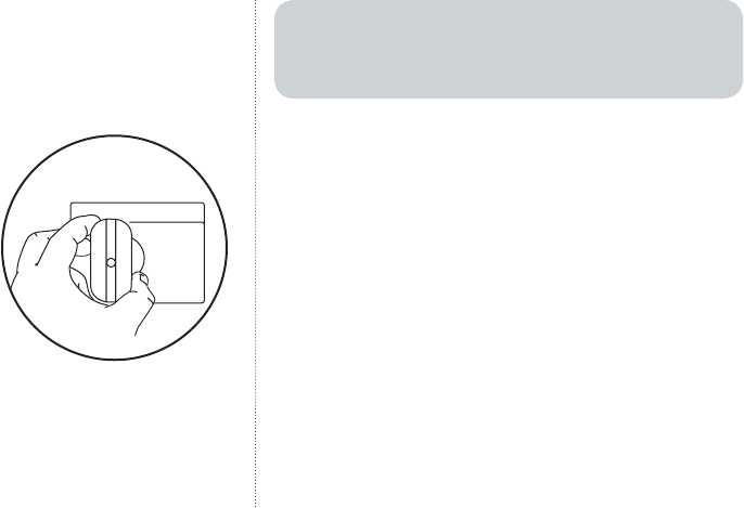
Manually operating the valve
CAUTION To reduce the risk of pinching your fingers: Power
must be disconnected before manually operating the valve.
The motor will resist manual operation while the power is on.
UNPLUG the unit.
ROTATE the Water Shut-Off Controller manually by turning
the Valve Handle to the correct position.
Note: Once power is restored, the Water Shut-Off Controller
will return to the position it was in when power was removed
CLOSED
Rotate to Open

26
Compliance Information
(Compliance Statement, Part 15.19): This device complies with Part 15 of
the FCC
Rules. Operation is subject to the following two conditions: (1) this device
may not cause harmful interference, and (2) this device must accept any
interference received, including interference that may cause undesired
operation.
WARNING (Part 15.21): Changes or modifications not expressly approved
by the party responsible for compliance could void the user’s authority to
operate this equipment.
To comply with FCC’s RF exposure limits for general population/
uncontrolled exposure, the antenna(s) used for this transmitter must
be installed to provide a separation distance of at least 20 cm from all
persons and must not be co-located or operating in conjunction with any
other antenna or transmitter.
Industry Canada Statement
The term “IC” before the certification/registration number only signifies
that the Industry Canada technical specifications were met.
Interference
This equipment has been tested and found to comply with the limits
for a Class B digital device, pursuant to Part 15 of the FCC rules. These
limits are designed to provide reasonable protection against harmful
interference in a residential installation. This equipment generates, uses,
and can radiate radio frequency energy and, if not installed and used in

27
accordance with the instructions, may cause harmful interference to radio
communications. However, there is no guarantee that interference will
not occur in a particular installation. If this equipment does cause harmful
interference to radio or television reception, which can be determined
by turning the equipment off and on, then the user is encouraged to try to
correct the interference by one or more of the following measures:
• Reorient or relocate the receiving antenna
• Increase the separation between the equipment and the receiver
• Connect the equipment into a power source on different circuit than
the receiver.
Sensor Maintenance
No serviceable parts. Clean with a soft, dry cloth.

28
Specifications
n Max. Working Pressure . . . . . . . . . . . . . . . . . . 125 PSIG
n Ambient Temperature . . . . . . . . . . . . . . . . . . . . 35º to 105º F
n Enclosure .............................. Polycarbonate
n Valve .................................. Full-Port, Brass, NPT
n Valve Seals ............................. RTFE
Flow Data
Valve Size CV = Gpm flow @ 1 PSI pressure drop
n Model: 70D5030G01, (CAT #: HHBVALVE50) . . . . . . 1/2” NPT . . . . . 19
n Model: 70D5030G02, (CAT #: HHBVALVE75) . . . . . . 3/4” NPT . . . . . 34
n Model: 70D5030G03, (CAT #: HHBVALVE100) . . . . . 1” NPT . . . . . . 52
n For cold water applications only
29
Notes:
30
Notes:
31
Notes:

Eaton Electrical Inc.
1000 Cherrington Parkway
Moon Township, PA 15108
www.homeheartbeat.com
© 2006 Eaton Corporation
All Rights Reserved
IM00416010E Rev. 1
Part No.: 67A5017H01
Need help?
Call Home Heartbeat Support
(1-800-813-2199 or www.homeheart-
beat.com) to get information
and instructions for service.