Echo Ppt 280 Owner S Manual
2014-07-05
: Echo Echo-Ppt-280-Owner-S-Manual echo-ppt-280-owner-s-manual echo pdf
Open the PDF directly: View PDF ![]() .
.
Page Count: 40
- Introduction
- Table of Contents
- Safety
- Emission Control (exhaust & evaporative)
- Description
- Contents
- Assembly
- handle shaft / drive shaft
- handle shaft / power head
- throttle linkage and ignition leads
- cutting attachment to drive shaft installation
- saw chain tension adjustment
- Operation
- fuel
- lubricating the guide bar and saw chain
- adjusting automatic oiler
- starting cold engine
- starting warm engine
- stopping engine
- pruning techniques
- Maintenance
- air filter
- fuel filter
- spark plug
- cooling system
- exhaust system
- carburetor adjustment
- guide bar and saw chain replacement
- filing saw chain
- Troubleshooting
- Storage
- Specifications
- Warranty Statements
- Servicing Information
Power PrunerTM
oPeraTor's Manual 1
Power PrunerTM
Operator's Manual
MODEL PPT-280
WARNING
Users of this equipment risk injury to themselves and others if the unit is used improp-
erly and/or safety precautions are not followed. ECHO provides an operator’s manual
and a safety manual. Both must be read and understood for proper and safe operation.
Failure to do so could result in serious injury.
X770001278
03/13
X7702091008

2
Copyright© 2013 By Echo, Incorporated
All Rights Reserved.
Table of ConTenTs
Introduction ................................................................2
- The Operator's Manual ........................................2
- The Safety Manual ..............................................2
Safety .........................................................................3
- Manual Safety Symbols and Important
Information .........................................................3
- International Symbols ......................................... 3
- Personal Condition and Safety Equipment ......... 4
- Kickback ............................................................. 6
- Equipment ...........................................................7
Emission Control .......................................................8
Description ................................................................. 8
Contents ................................................................... 11
Assembly.................................................................. 11
- Handle Shaft/Drive Shaft .................................. 11
- Handle Shaft/Power Head .................................12
- Throttle Linkage and Ignition Leads ................13
- Cutting Attachment to Drive Shaft Installation 14
- Saw Chain Tension Adjustment ........................ 15
Operation ..................................................................16
- Fuel ...................................................................17
- Lubricating the Guide Bar and Saw Chain ....... 18
- Adjusting Automatic Oiler ................................18
- Starting Cold Engine .........................................19
- Starting Warm Engine .......................................20
- Stopping Engine ................................................20
- Pruning Techniques ...........................................21
Maintenance ............................................................. 22
- Skill Levels .......................................................22
- Maintenance Intervals .......................................22
- Air Filter ...........................................................23
- Fuel Filter ..........................................................23
- Spark Plug .........................................................24
- Cooling System Cleaning .................................24
- Exhaust System .................................................25
- Carburetor Adjustment ......................................27
- High Altitude Operation .................................27
- Lubrication ........................................................28
- Guide Bar and Saw Chain Replacement ...........29
- Filing Saw Chain ..............................................30
Troubleshooting ....................................................... 33
Storage .....................................................................34
Specications ...........................................................35
Warranty Statements ................................................36
Servicing Information ..............................................40
- Parts ..................................................................40
- Service ..............................................................40
- ECHO Consumer Product Support ................... 40
- Warranty Card ...................................................40
- Additional or Replacement Manuals ................40
Specications, descriptions and illustrative material
in this literature are as accurate as known at the time
of publication, but are subject to change without
notice. Illustrations may include optional equipment
and accessories, and may not include all standard
equipment.
InTroduCTIon
Welcome to the ECHO family. This ECHO product was designed and manufactured to provide long life and on-the-job-
dependability. Read and understand this manual and the SAFETY MANUAL. You will nd both easy to use and full of
helpful operations tips and SAFETY messages.
The operaTor's manual
Keep it in a safe place for future reference. Contains specications and
information for safety, operation, maintenance, storage, and assembly
specic to this product.
The safeTy manual
Keep it in a safe place for future reference. Explains possible hazards
and the measures you should take to insure safe operation.
Power PrunerTM
oPeraTor's Manual 3
safeTy
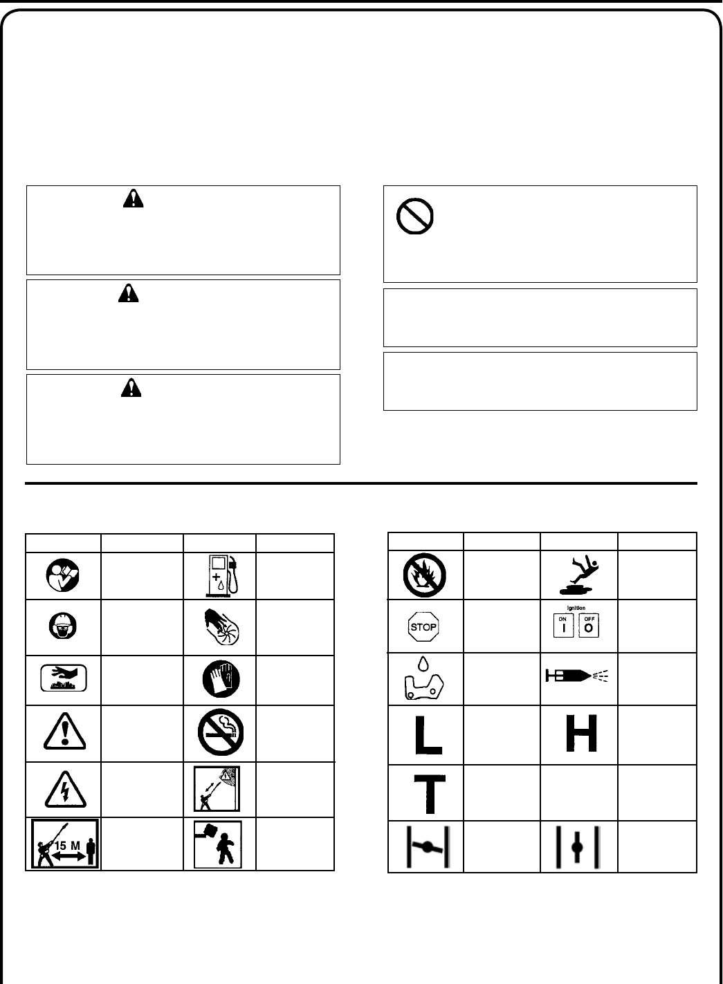
manual safeTy symbols and ImporTanT InformaTIon
Hot
Surface
Symbol
description/application Symbol form/shape Symbol
description/application
Symbol form/shape
Read and understand
Operator's Manual.
Wear eyes, ears and
head protection
Fuel and oil mixture
Finger Severing
Safety/Alert
Avoid all power lines.
This unit is not insu-
lated against electri-
cal current.
Do not operate closer
than 15 M (50 ft.) from
electrical hazards.
Keep bystanders
at least 15 meters
(50 feet) away.
Plan retreat
path from falling
objects.
Wear hand
protection. Use
two handed.
DO NOT smoke
near fuel.
InTernaTIonal symbols
Symbol
description/application Symbol form/shape Symbol
description/application
Symbol form/shape
Carburetor adjustment
- Idle speed
Carburetor adjustment
- High speed mixture
Emergency stop
Carburetor adjustment
- Low speed mixture
DO NOT allow
ames or sparks
near fuel.
Wear slip resistant
foot wear.
Ignition
ON/OFF
Chain lubrication Primer bulb
Choke Control
"Cold Start"
Position
(Choke Closed)
Choke Control
"Run"
Position
(Choke Open)
WARNING
The safety alert symbol accompanied by the word
“WARNING” calls attention to an act or condi-
tion which CAN lead to serious personal injury or
death if not avoided.
CIRCLE AND SLASH SYMBOL
This symbol means the specic action
shown is prohibited. Ignoring these prohi-
bitions can result in serious or fatal injury.
CAUTION
The safety alert symbol accompanied by the word
“CAUTION” calls attention to an act or condition
which may lead to minor or moderate personal
injury if not avoided.
NOTE
This enclosed message provides tips for use, care and
maintenance of the unit.
IMPORTANT
The enclosed message provides information neces-
sary for the protection of the unit.
DANGER
The safety alert symbol accompanied by the word
“DANGER” calls attention to an act or condition
which WILL lead to serious personal injury or
death if not avoided.
Throughout this manual and on the product itself, you will nd safety alerts and helpful, informational messages pre-
ceded by symbols or key words. The following is an explanation of those symbols and key words and what they mean to
you.
4
Vibration and Cold
It is believed that a condition called Raynaud’s Phenomenon, which affects the ngers of certain individuals may be
brought about by exposure to vibration and cold. Exposure to vibration and cold may cause tingling and burning sen-
sations followed by loss of color and numbness in the ngers. The following precautions are strongly recommended
because the minimum exposure which might trigger the ailment is unknown.
• Keep your body warm, especially the head, neck, feet, ankles, hands
and wrists.
• Maintain good blood circulation by performing vigorous arm
exercises during frequent work breaks and also by not smoking.
• Limit the hours of operation. Try to ll each day with jobs where
operating the unit or other hand-held power equipment is not
required.
• If you experience discomfort, redness, and swelling of the ngers
followed by whitening and loss of feeling, consult your physician
before further exposing yourself to cold and vibration.
personal CondITIon and safeTy equIpmenT
WARNING
Users of this product risk injury to themselves and others if the unit is used improperly and/or safety precautions
are not followed. Proper clothing and safety gear must be worn when operating unit.
Physical Condition
Your judgment and physical dexterity may not be good:
• if you are tired or sick,
• if you are taking medication,
• if you have taken alcohol or drugs.
Operate unit only if you are physically and mentally well.
Eye Protection
Wear eye protection that meets ANSI Z87.1 or CE re-
quirements whenever you operate the unit
Face and Head Protection
When trimming overhead, always wear head protection
meeting ANSI Z89.1 or CE requirements with a full face
shield. Head protection with full face shield will help
protect you from falling branches and debris.
Hand Protection
Wear no-slip, heavy duty work gloves to improve your
grip on the unit handles. Gloves also reduce the transmis-
sion of machine vibration to your hands.
Proper Clothing
Wear snug tting, durable clothing;
• Pants should have long legs, shirts with long sleeves.
• DO NOT WEAR SHORTS,
• DO NOT WEAR TIES, SCARVES, JEWELRY,
or clothing with loose or hanging items that could
become entangled in moving parts or surrounding
growth.
Wear sturdy work shoes with nonskid soles;
• DO NOT WEAR OPEN TOED SHOES,
• DO NOT OPERATE UNIT BAREFOOTED.
Wear no-slip, heavy duty work gloves.
Keep long hair away from engine and air intake. Retain
hair with cap or net.
Hot Humid Weather
Heavy protective clothing can increase operator fatigue
which may lead to heat stroke. Schedule heavy work for
early morning or late afternoon hours when temperatures
are cooler.
WARNING
The ignition components of this machine generate an electromagnetic eld during operation which may interfere
with some pacemakers. To reduce the risk of serious or fatal injury, persons with pacemakers should consult with
their physician and the pacemaker manufacturer before operating this machine. In the absence of such informa-
tion, ECHO does not recommend the use of ECHO products by anyone who has a pacemaker.
Hearing Protection
ECHO recommends wearing hearing protection whenever
unit is used.
Power PrunerTM
oPeraTor's Manual 5
DANGER
All over head electrical conductors and communications wires can
have electricity ow with high voltages. This unit is not insulated
against electrical current. Never touch wires directly or indirectly
when pruning, otherwise serious injury or death may result.
WARNING
Do not operate this product indoors or in inadequately ventilated
areas. Engine exhaust contains poisonous emissions and can cause
serious injury or death.
Read the Manuals
• Provide all users of this equipment with the Operator’s Manual and
Safety Manual for instructions on Safe Operation.
Clear the Work Area
• Spectators and fellow workers must be warned, and children and
animals prevented from coming nearer than 15 m (50 ft.) while the
unit is in use.
Use Proper Clothing & Equipment
• Always wear head protection with full face shield to help protect
against falling branches and debris.
Keep A Firm Grip
• Grip Power PrunerTM with both hands with thumbs and ngers encir-
cling the handle, and shaft tube.
Repetitive Stress Injuries
It is believed that overusing the muscles and tendons of the ngers, hands, arms and shoulders may cause soreness,
swelling, numbness, weakness and extreme pain in those areas. Certain repetitive hand activities may put you at a high
risk for developing a Repetitive Stress Injury (RSI). An extreme RSI condition is Carpal Tunnel Syndrome (CTS), which
could occur when your wrist swells and squeezes a vital nerve that runs through the area. Some believe that prolonged
exposure to vibration may contribute to CTS. CTS can cause severe pain for months or even years.
To reduce the risk of RSI/CTS, do the following:
• Avoid using your wrist in a bent, extended or twisted position. In-
stead try to maintain a straight wrist position. Also, when grasping,
use your whole hand, not just the thumb and index nger.
• Take periodic breaks to minimize repetition and rest your hands.
• Reduce the speed and force with which you do the repetitive move-
ment.
• Do exercises to strengthen the hand and arm muscles.
• Immediately stop using all power equipment and consult a doctor if
you feel tingling, numbness or pain in the ngers, hands, wrists or
arms. The sooner RSI/CTS is diagnosed, the more likely permanent
nerve and muscle damage can be prevented.
6
WARNING
Kickback can lead to dangerous loss of control of the Power PrunerTM and result in serious injury to the operator or
any one standing close by. Hold the Power PrunerTM rmly with both hands with thumbs and ngers encircling the
front and rear handles. Be aware of the down and outward path the pruner will take after the cut is made.
kICkbaCk
Kickback may occur when the moving saw chain at the nose or tip of
the guide bar touches an object, or when the wood closes in and pinches
the saw chain in the cut. In some cases this may cause a lightning-fast
reverse action, kicking the guide bar and saw chain up and back or
down and back towards the operator. Either of these reactions may
cause the operator to lose control of the Power PrunerTM which could
result in serious personal injury.
With a basic understanding of kickback, you can reduce or eliminate
the element of surprise which contributes to accidents.
Avoid contact of the guide bar tip with any object while the saw chain
is moving.
Cut only wood. Avoid striking concrete, metal, wire, or other obstruc-
tions which could cause kickback or damage to the saw chain.
If the saw chain does strike a foreign object, immediately stop the en-
gine, inspect and repair the Power PrunerTM if necessary.
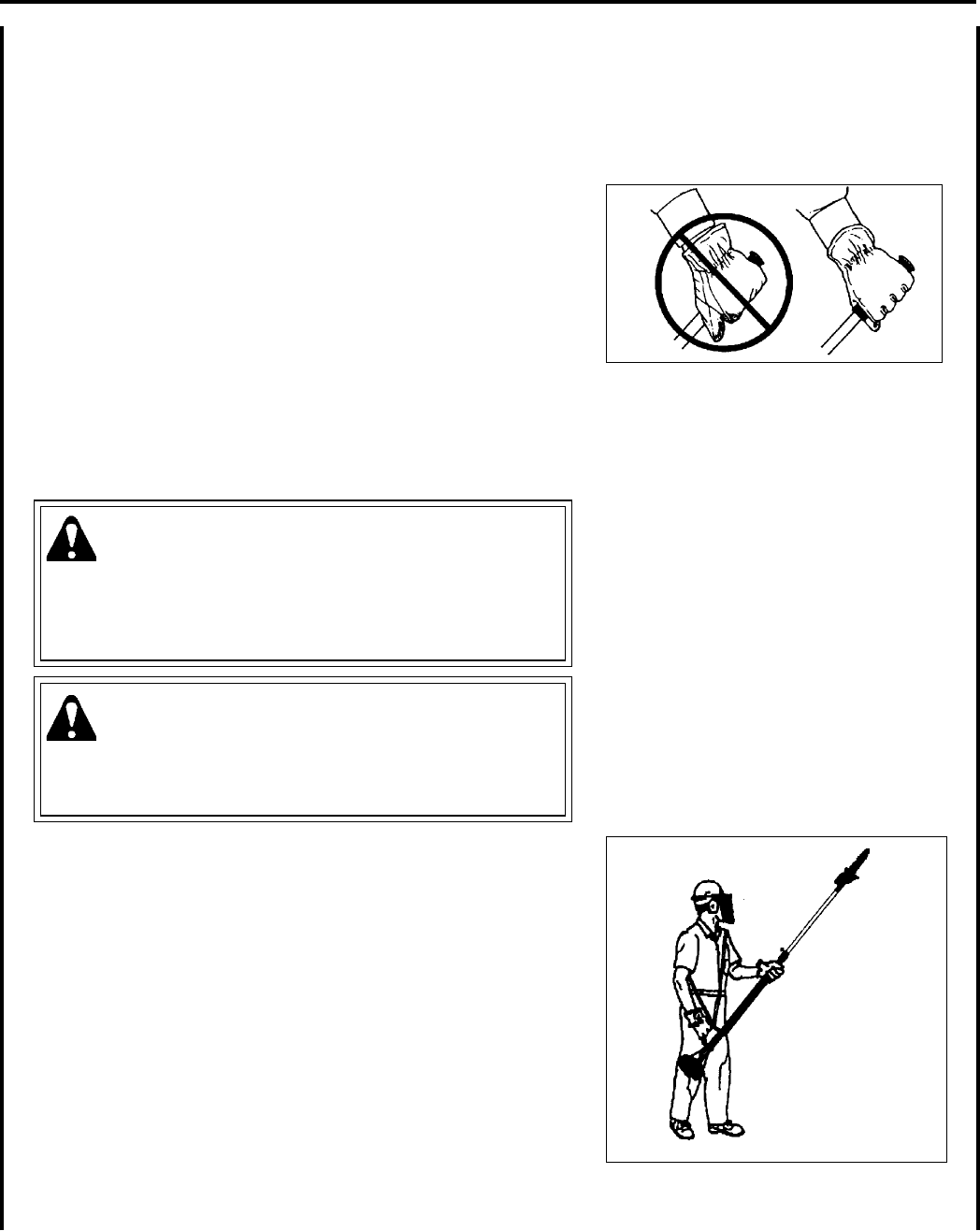
Keep A Solid Stance
• Maintain footing and balance at all times. Do not stand on slippery,
uneven or unstable surfaces. Do not work in odd positions or on
ladders. Do not overreach.
• Operate the Power PrunerTM only from the ground or out of an ap-
proved bucket lift.
• Always evaluate the branches to be pruned for hazards such as loose
dead branches which may fall and strike the operator or helpers.
Remove hazards before pruning.
• Plan retreat path from falling objects.
• Cut branches bounce when striking ground.
• Check that shoulder harness is adjusted for safe, comfortable opera-
tion. See picture at right for proper adjustment.
• Turn the Power PrunerTM off when moving from tree to tree.
• Avoid any contact with saw chain.
Avoid Hot Surfaces
• Keep exhaust area clear of ammable debris. Avoid contact during
and immediately after operation.
Transporting Unit
• When transporting the unit, empty the fuel tank, put the unit in an
upright position, and secure it rmly. Failure to do so could result in
damage or injury.

Power PrunerTM
oPeraTor's Manual 7
equIpmenT
WARNING
Serious injury may result from the use of non-approved guide bar and saw chain combinations. ECHO, INC. will not
be responsible for the failure of cutting devices or accessories which have not been tested and approved by ECHO
for use with this unit. Read and comply with all safety instructions listed in this manual.
• Check unit for loose/missing nuts, bolts, and screws. Tighten and/or replace as needed.
Guide Bar and Saw Chain
• Check that the cutting attachment, guide bar, and saw chain is rmly attached and in safe operating condition.
• Use only one Echo-approved extension on the pruner.
• Do not hit rocks, stones, tree stumps, and other foreign objects with the saw chain.
• Do not cut into the ground with the saw chain.
• If cutting attachment end strikes an obstruction, stop engine immediately and inspect saw chain for damage.
• Do not operate with a dull, fractured, or discolored saw chain.
• Remove all foreign objects from work area.
• Always cover the guide bar and saw chain with guide bar cover during transportation and for storage.
WARNING
Moving parts can amputate ngers or cause severe injuries. Keep hands, clothing and loose objects away from all
openings.
• ALWAYS stop engine, disconnect spark plug, and make sure all moving parts have come to a complete stop
before removing obstructions, clearing debris, or servicing unit.
• DO NOT start or operate unit unless all guards and protective covers are properly assembled to unit.
• NEVER reach into any opening while the engine is running. Moving parts may not be visible through openings.
WARNING
Check fuel system for leaks due to fuel tank damage, especially if the unit is dropped. If damage or leaks are found,
do not use unit, otherwise serious personal injury or property damage may occur. Have unit repaired by an autho-
rized servicing dealer before using.
8
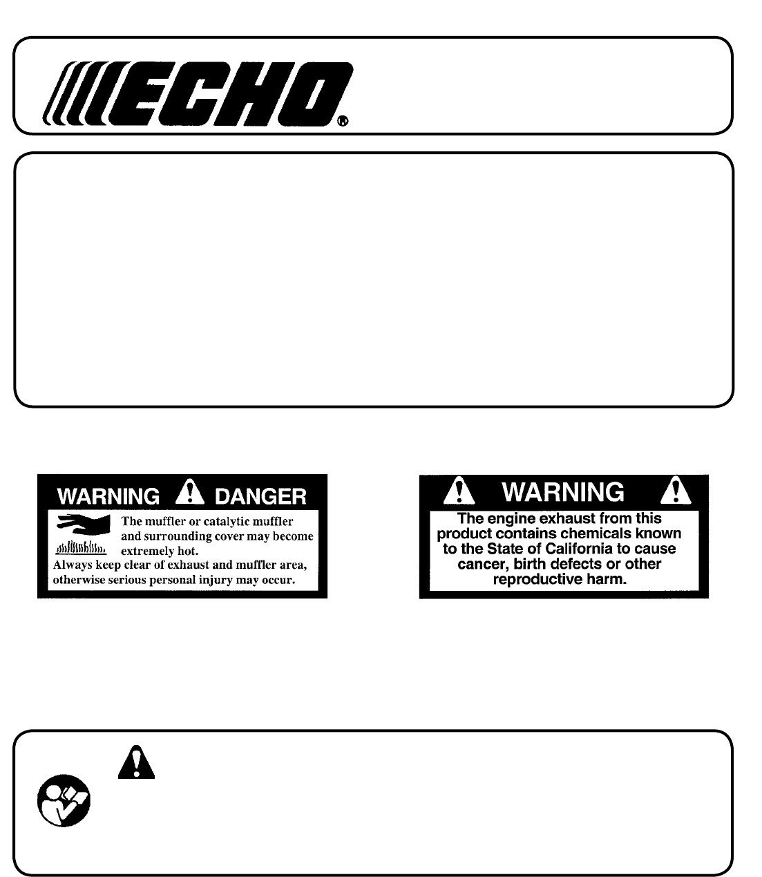
Hot Decal (near mufer)
desCrIpTIon
Locate these safety decals on your unit. Make sure the decals are legible and that you understand and follow the instruc-
tions on them. If a decal cannot be read, a new one can be ordered from your ECHO dealer. See PARTS ORDERING
instructions for specic information.
14
13
15
16
17
18
20
19
21
An Emission Control Label is located on the engine.
(This is an EXAMPLE ONLY, information on label varies
by engine FAMILY).
emIssIon ConTrol (eXhausT & evaporaTIve)
EPA 2010 and Later and/or C.A.R.B. TIER III
PRODUCT EMISSION DURABILITY (EMISSION COMPLIANCE PERIOD)
The 50 or 300 hour emission compliance period is the time span selected by the manufacturer certifying the engine
emissions output meets applicable emissions regulations, provided that approved maintenance procedures are fol-
lowed as listed in the Maintenance Section of this manual.
The emission control system for the engine is EM (engine
modication) and, if the second to last character of the
Engine Family on the Emission Control Information label
(sample below) is “C”, “K”, or “T”, the emission control
system is EM and TWC (3-way catalyst). The fuel tank/fuel
line emission control system is EVAP (evaporative emis-
sions). Evaporative emissions for California models are only
applicable to fuel tanks.
Power PrunerTM
oPeraTor's Manual 9
1
12
11
10
2
9
8
7
6
5
4
22
3

10
1. POWER HEAD - Includes the Engine, Clutch, Fuel System, Ignition System and Starter.
2. THROTTLE TRIGGER - Spring loaded to return to idle when released. During acceleration press trigger gradu-
ally for best operating technique.
3. SHOULDER HARNESS - An adjustable strap that suspends the unit from the operator.
4. CUTTING ATTACHMENT - Sealed, gear ratio is 1.5:1 reduction.
5. CUTTING SHOE - Used to capture and stabilize branch while cutting. Place cutting shoe against branch, acceler-
ate and lower saw chain into branch.
6. GUIDE BAR - 305 mm (12 in.) guide bar.
7. SAW CHAIN - Chain, serving as a cutting tool.
8. AUTOMATIC OILER ASSEMBLY - Self oiling. Use high quality, low viscosity, non detergent bar and chain oil.
9. LOWER SHAFT TUBE - Durable berglass mesh housing.
10. STOP SWITCH - Mounted on top of handle assembly. Move switch forward to run, back to stop.
11. THROTTLE TRIGGER LOCKOUT - This lever must be depressed before throttle trigger can be operated.
12. THROTTLE HANDLE ASSEMBLY - Sturdy handle for right hand placement. Includes stop switch and throttle
trigger.
13. TOP GUARD - Protects arm from hot engine.
14. RECOIL STARTER - Pull recoil handle slowly until starter engages, then quickly and rmly. When engine starts
return handle slowly. DO NOT let handle snap back or damage will occur.
15. SPARK ARRESTOR MUFFLER OR SPARK ARRESTOR MUFFLER WITH CATALYST - The mufer or
catalytic mufer controls exhaust noise and emission. The spark arrestor screen prevents hot, glowing particles of
carbon from leaving the mufer. Keep exhaust area clear of ammable debris.
16. FUEL TANK - Contains fuel and fuel lter.
17. FUEL TANK CAP - Covers and seals fuel tank opening.
18. PURGE BULB - Pumping purge bulb before starting engine draws fresh fuel from the fuel tank, purging air from
the carburetor. Pump purge bulb until fuel is visible and ows freely in the clear fuel tank return line. Pump purge
bulb an additional 4 or 5 times.
19. CHOKE - Located above air cleaner housing. Move lever to starting position ( ) (close choke) and back to run
position ( ) (open choke).
20. AIR CLEANER ASSEMBLY - Contains replaceable air lter element.
21. SPARK PLUG - Provides spark to ignite fuel mixture.
22. GUIDE BAR COVER - Used to cover guide bar and saw chain during transport and storage. Remove guide bar
cover before using unit.
Power PrunerTM
oPeraTor's Manual 11
assembly
Parts Required: Power Head, Handle Shaft Assembly, Drive Shaft
Assembly, Cutting Attachment
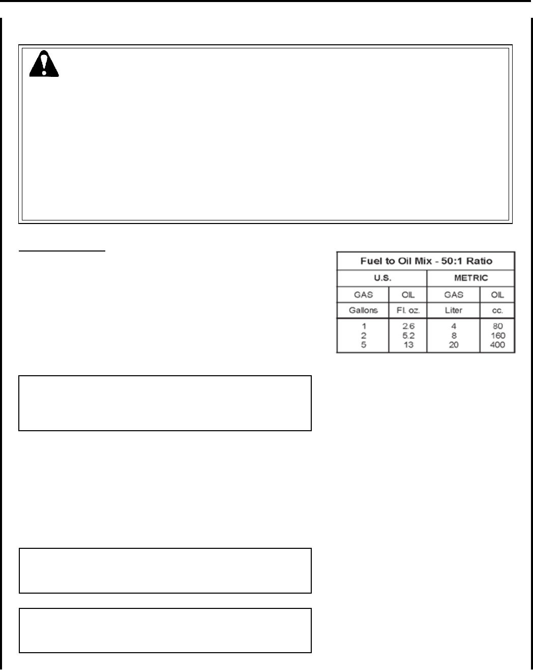
handle shafT / drIve shafT
1. Remove protective caps from handle shaft assembly.
2. Loosen clamping bolts (A) on drive shaft.
3. Pull exible drive shaft coupler (B) 2 -3 inches out of handle shaft.
A
B
ConTenTs
Due to packaging restriction the ECHO product you have purchased requires some assembly.
After opening the carton, check for damage. Immediately notify your retailer or ECHO Dealer of damaged or missing
parts. Use the contents list to check for missing parts.
___ Power Head
___ Handle Shaft Assembly
___ Drive Shaft Assembly
___ Cutting Attachment W/ Guide Bar and Saw Chain
___ Operator's Manual
___ Emission Control Warranty Statement
___ Safety Manual
___ Warranty Registration Cardt
___ Assembly Tool (s)
___ Safety Glasses
___ Shoulder Harness
___ Guide Bar Cover
DECLARACIÓN DE GARANTÍA DE CONTROL DE EMISIONES DE ECHO INCORPORATED
PARA LAS MARCAS ECHO Y SHINDAIWA
La Agencia de Protección Medioambiental (EPA) y la Junta de Recursos de Aire de California (C.A.R.B.) y ECHO Incorporated (ECHO Inc.) tienen el
placer de explicar la garantía del sistema de control de emisiones en su equipo o motor pequeño que no sea para desplazamiento por carretera (SORE)
de 2010 o posteriores. Los nuevos equipos/SORE deben diseñarse, fabricarse y equiparse de modo que cumplan con las estrictas normas anticontami-
nación de EPA y CARB. ECHO Inc debe garantizar el sistema de control de emisiones en su equpo/SORE para los períodos citados a continuación,
siempre que no haya habido ningún abuso, negligencia o mantenimiento indebido de su equipo/SORE. El sistema de control de emisiones puede incluir
piezas tales como: carburador, sistema de inyección de combustible, sistema de encendido, convertidor catalítico/silenciador, depósito de combustible,
líneas de alimentación de combustible, conjunto de tapa de combustible, bujías, ltros de aire y otros componentes relacionados. Donde exista una
condición cubierta por la garantía, ECHO Inc reparará su equipo/SORE de forma gratuita, incluido el diagnóstico, las piezas y la mano de obra. La
garantía del sistema de control de emisiones se extiende al propietario original incluidos todos los propietarios subsiguientes.
COBERTURA DE GARANTÍA DEL FABRICANTE:
El sistema de control de emisiones está garantizado durante 2 años o mientras dure la garantía de ECHO Inc, lo que sea más largo. Si cualquier pieza
relacionada con las emisiones de su equipo es defectuosa, la pieza será reparada o reemplazada por ECHO Inc. o su representante de servicio autor-
izado.
RESPONSABILIDADES DEL PROPIETARIO RELACIONADAS CON LA GARANTÍA:
Como propietario del equipo/SORE, usted es responsable de llevar a cabo el mantenimiento requerido indicado en el manual del operador. ECHO Inc.
recomienda que guarde todos los recibos de mantenimiento de su equipo/SORE, no obstante ECHO Inc. no puede negar la garantía solamente por
falta de recibos o por no asegurarse de llevar a cabo todo el mantenimiento programado. Como propietario del equipo/SORE debe ser consciente de
que ECHO Inc. puede rechazar su cobertura de garantía si su equipo/SORE o una pieza ha fallado debido abuso, negligencia, mantenimiento indebido
o modicaciones no aprobadas.
Usted es responsable de llevar a su equipo/SORE a un representante de servicio autorizado por ECHO Inc. tan pronto como surja un problema. Las
reparaciones de garantía deben completarse en un período razonable, que no debe sobrepasar los 30 días. Si existe una condición cubierta por la
garantía y no hay un distribuidor autorizado en un radio de 100 millas, ECHO Inc. pagará el envío de la unidad al distribuidor autorizado más cercano.
Si tiene dudas sobre la cobertura de la garantía, debe ponerse en contacto con ECHO Inc. llamando al 1-800-673-1558, sitio web WWW.ECHO-USA.
COM o ponerse en contacto con Shindaiwa al 1-877-986-7783, visitando el sitio web WWW.SHINDAIWA.COM.
¿QUE CUBRE ESTA GARANTÍA?
ECHO Inc. garantiza que su equipo/SORE fue diseñado, fabricado y equipado para cumplir con las normas de emisiones de EPA y CARB correspon-
dientes y que su equipo/SORE no tiene defectos ni de material ni de elaboración que haga que no cumpla con los requisitos correspondientes durante
2 años o mientras dure la garantía de ECHO Inc., lo que sea más largo. El periodo de garantía empieza en la fecha en que el usuario nal compre el
producto.
¿CÓMO SE CORREGIRÁ UNA PIEZA CUBIERTA?
Si hay un defecto en una pieza cubierta por esta garantía, cualquier Distribuidor de servicio autorizado de ECHO Inc. corregirá el defecto. No tendrá
que pagar nada para ajustar, reparar o reemplazar la pieza. Esto incluye cualquier mano de obra y diagnóstico para reparaciones garantizadas por el
distribuidor. Además estarán garantizadas las piezas de motor que no estén expresamente cubiertas por esta garantía pero cuya falla sea consecuencia
de la falla de una pieza cubierta.
¿QUÉ PIEZAS ESTÁN CUBIERTAS?
Cualquier pieza correspondiente relacionada con emisiones que no esté programada para el “mantenimiento requerido” será reparada o reemplazada
en el período de garantía. La pieza reparada o reemplazada estará garantizada durante el resto del período de garantía de ECHO Inc.
Cualquier pieza garantizada que esté programada solamente para su inspección regular en las instrucciones escritas proporcionadas está garantizada
durante el período de garantía indicado arriba. Cualquier pieza reparada o reemplazada estará garantizada durante el resto del período de garantía de
ECHO Inc.
Cualquier pieza relacionada con emisiones programada para sustituirse durante el “mantenimiento requerido” estará garantizada durante el período
antes del primer punto de sustitución programada para esa pieza. Cualquier pieza reparada o reemplazada cubierta por la garantía debe garantizarse
durante el resto del período antes del primer punto de reemplazo programado para esa pieza.
Cualquier pieza de repuesto aprobada por el fabricante puede usarse para llevar a cabo cualquier mantenimiento o reparaciones cubiertos por la ga-
rantía en las piezas relacionadas con las emisiones, y deben proveerse de forma gratuita si la pieza sigue cubierta por la garantía.
Se puede usar cualquier pieza de repuesto que sea equivalente en rendimiento y durabilidad en el mantenimiento o reparaciones no cubiertos por la
garantía y no debe reducir las obligaciones de la garantía del fabricante.
Durante el peróodo de garantía del equipo/SORE, ECHO Inc. mantendrá un inventario de piezas garantizadas suciente para cumplir con la demanda
esperada de las mismas.
PIEZAS GARANTIZADAS RELACIONADAS CON EMISIONES ESPECÍFICAS:
• Sistema de encendido electrónico • Bujía
• Conjunto de convertidor catalítico/silenciador • Carburador (conjunto completo o componentes de repuesto)
• Estrangulado • Conjunto de inyección de combustible (o componentes de repuesto)
• Depósito de combustible • Conjunto de tapa de combustible
• Filtro de aire • Línea de alimentación de combustible (y abrazaderas/conectores relacionados
correspondientes)
¿QUÉ NO ESTÁ CUBIERTO?
Cualquier falla ocasionada por abuso, negligencia, mantenimiento indebido, modicaciones no aprobadas, uso de piezas agregadas no aprobadas/
piezas modicadas o accesorios no aprobados.
Esta garantía de control de emisiones es válida solamente en EE.UU., sus territorios y Canadá. 99922201033
01/2010

12
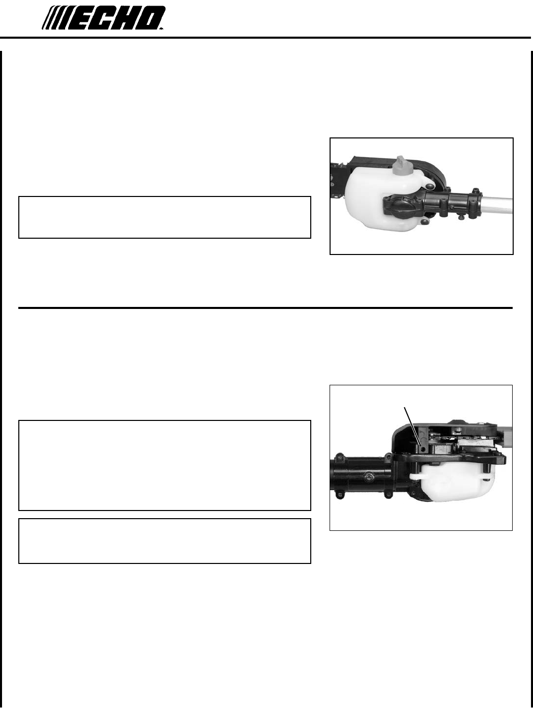
handle shafT / power head
1. Loosen two (2) clamping screws (A) and remove locating screw
(B).
2. Pull exible drive shaft coupler (C) 2-3 in. out of handle shaft as-
sembly.
3. Align exible drive shaft coupler with engine socket and slide
together until locating hole in shaft is visible through locating hole
in engine housing.
4. Install locating screw (B) and tighten clamping bolts (A).
4. Align exible drive shaft coupler with drive shaft socket and slide
together until handle shaft is fully seated into drive shaft.
5. Tighten clamping bolts (A).
A
B
AA
B
A
A
C
Power PrunerTM
oPeraTor's Manual 13
A
BC
D
ThroTTle lInkage and IgnITIon leads
1. Close choke and remove air lter cover.
2. Place inner throttle cable in large hole of carburetor swivel (A).
3. Loosen nuts (B) and place threaded end of throttle linkage in
bracket slot. Finger tighten nuts (B).
4. Check throttle for freedom of movement and that wide open
throttle / low idle extremes are adjusted properly. If adjustment
cannot be achieved with adjusting nuts (B), consult with your Echo
Dealer for correct adjustment procedure. Tighten nuts (B).
5. Connect 2 ignition stop leads (C,D) from throttle cable tubing to 2
ignition leads (C,D) on engine.
6. Gather ignition wires and position behind air lter case.
7. Install air lter and cover.
A
B
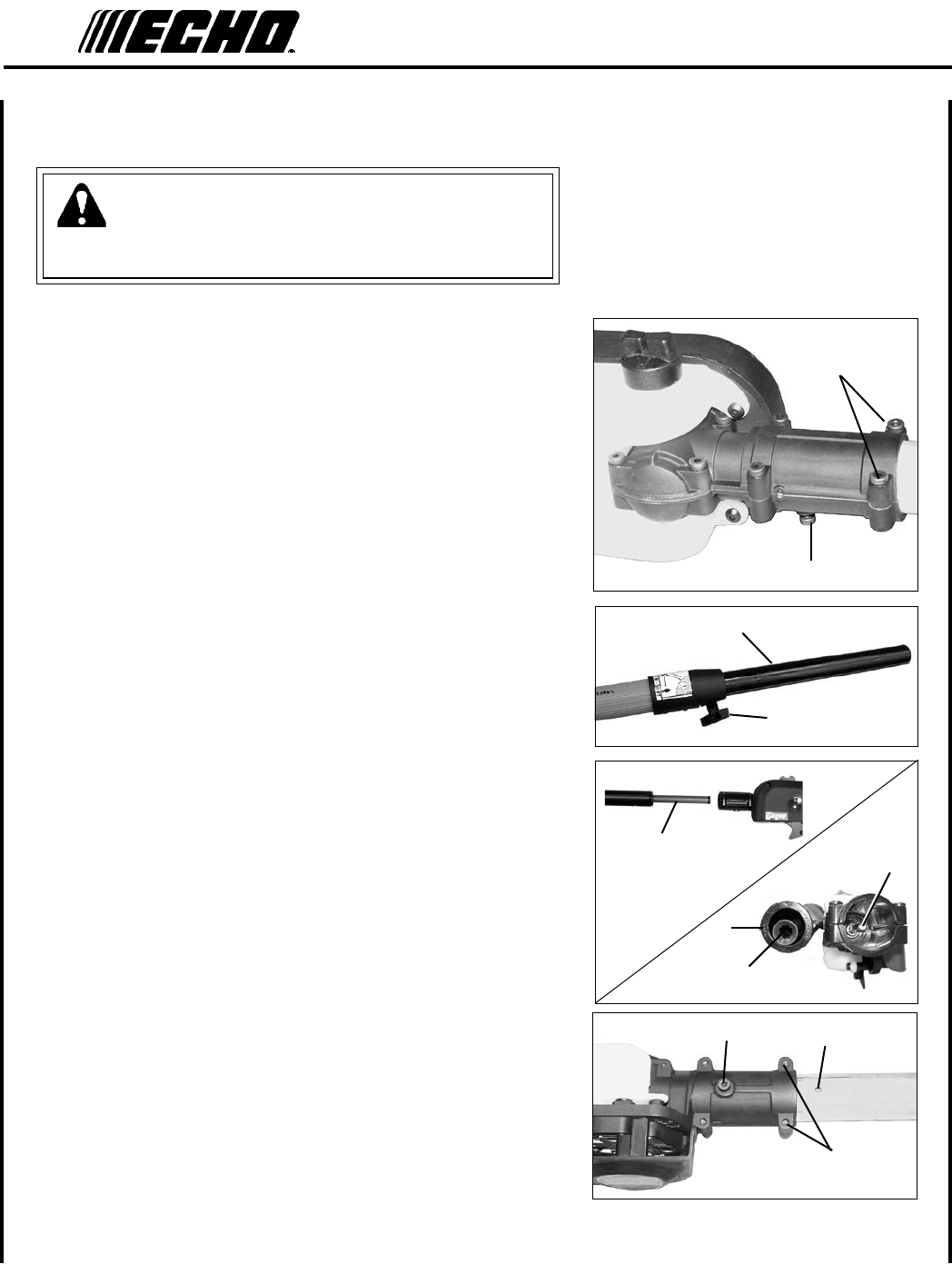
14
WARNING
Saw Chain is sharp! Always wear gloves when handling assembly,
otherwise serious personal injury may result.
1. Loosen the two (2) screws (C) and remove locator screw (D) on
cutting attachment.
2. Loosen clamp knob (E) turning counter clockwise.
3. Pull upper tube (F) out of berglass lower tube 127-152 mm (5-6
in.), then slide (F) back into berglass lower tube exposing inner
drive shaft (G). Align and join star shaped drive end of inner drive
shaft (G) with cutting attachment shaft (H).
4. Align ridges (J) on upper tube with seams in cutting attachment.
5. Slide together, aligning locator hole (D) in cutting attachment with
locating hole (I) in upper tube.
6. Install and tighten locator screw (D). Tighten two (2) cutting at-
tachment screws (C).
7. Extend upper tube to desired length. Tighten clamp knob (E) turn-
ing clockwise.
d
C
CuTTIng aTTaChmenT To drIve shafT InsTallaTIon
C
I
GH
G
E
F
J
d
Power PrunerTM
oPeraTor's Manual 15
A
B
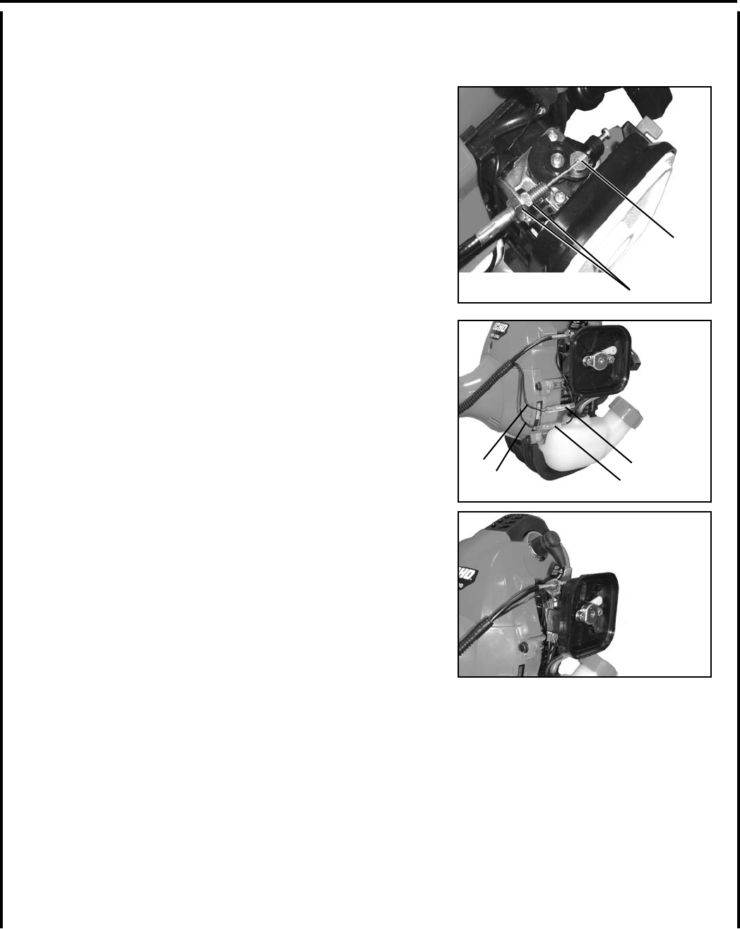
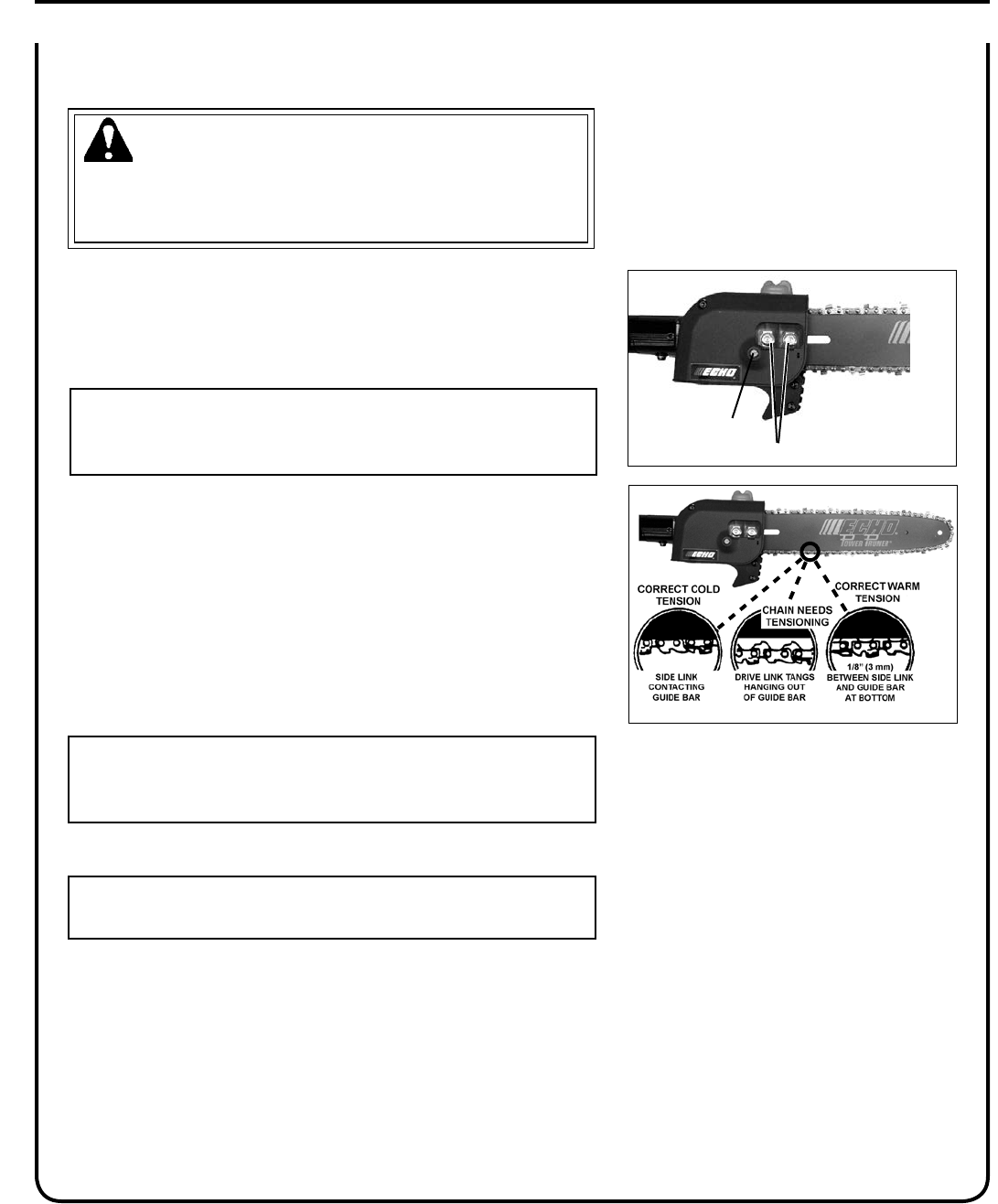
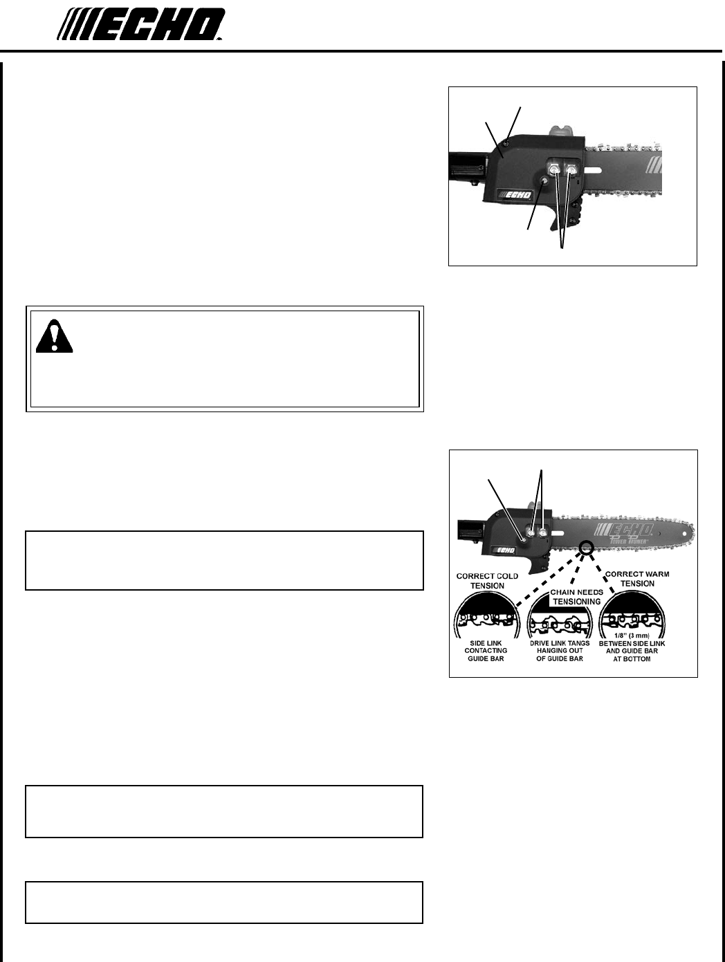
saw ChaIn TensIon adjusTmenT
WARNING
Always disconnect spark plug wire before servicing cutting attach-
ment. Wear gloves when handling saw chain, otherwise serious
personal injury may result.
To Adjust Saw Chain Tension
1. Move stop switch to STOP position.
2. Disconnect spark plug lead.
3. Loosen two guide bar nuts (A) until nger tight.
IMPORTANT
Always loosen guide bar nuts before turning the chain tension ad-
juster, otherwise the clutch cover and tensioner will be damaged.
4. Hold the bar nose up, and turn the adjuster screw (B) clockwise un-
til the chain ts snugly against the underside of the bar, as shown.
Cold Chain Only - turn adjuster screw CW an additional 1/8 - 1/4
turn.
5. Tighten both guide bar nuts with nose held up. Tighten rear nut
rst.
6. Pull the chain around the guide bar by hand. Reduce the chain ten-
sion if you feel tight spots.
7. When chain is properly tensioned, tighten guide bar nuts securely.
IMPORTANT
Tighten guide bar nuts to 8 - 9 N•m (71 - 80 in. lbs.) DO NOT
over-tighten nuts. Damage may result.
8. Keep chain properly tensioned at all times.
NOTE
All chains require frequent adjustment.
9. Connect spark plug lead.
16
NOTICE: Use of unmixed, improperly mixed, or fuel older than 90 days, (stale fuel), may cause hard starting, poor
performance, or severe engine damage and void the product warranty. Read and follow instructions in the Storage
section of this manual.
WARNING
Alternative fuels, such as E-15 (15% ethanol), E-85 (85% ethanol) or any fuels not meeting ECHO requirements are
NOT approved for use in ECHO 2-stroke gasoline engines. Use of alternative fuels may cause performance prob-
lems, loss of power, overheating, fuel vapor lock, and unintended machine operation, including, but not limited to,
improper clutch engagement. Alternative fuels may also cause premature deterioration of fuel lines, gaskets, carbure-
tors and other engine components.
Fuel Requirements
Gasoline - Use 89 Octane [R+M/2] (mid grade or higher) gasoline known to be good quality. Gasoline may contain up to
10% Ethanol (grain alcohol) or 15% MTBE (methyl tertiary-butyl ether). Gasoline containing methanol (wood alcohol)
is NOT approved.
Two Stroke Oil - A two-stroke engine oil meeting ISO-L-EGD (ISO/CD 13738) and J.A.S.O. FD Standards must be
used. Echo brand premium Power Blend X TM Universal 2-Stroke Oil meets these standards. Engine problems due to
inadequate lubrication caused by failure to use an (ISO/CD 13738) and J.A.S.O. FD certied oil, such as Echo premium
Power Blend X TM, will void the two-stroke engine warranty.
IMPORTANT
Echo premium Power Blend X TM Universal 2-Stroke Oil may be mixed at 50:1 ratio for application in all Echo en-
gines sold in the past regardless of ratio specied in those manuals.
operaTIon
WARNING
Moving parts can amputate ngers or cause severe injuries. Keep hands, clothing, and loose objects away from
all openings. Always stop engine, disconnect spark plug, and make sure all moving parts have come to a complete
stop before removing obstructions, clearing debris, or servicing unit.
fuel
WARNING
Operation of this equipment may create sparks that can start res. This unit is equipped with a spark arrestor to
prevent discharge of hot particles from the engine. Metal blade use also can create sparks if the blade strikes rocks,
metal, or other hard objects. Contact local re authorities for laws or regulations regarding re prevention require-
ments.
Power PrunerTM
oPeraTor's Manual 17
Mixing Instructions
1. Fill an approved fuel container with half of the required amount of
gasoline.
2. Add the proper amount of 2-stroke oil to gasoline.
3. Close container and shake to mix oil with gasoline.
4. Add remaining gasoline, close fuel container, and remix.
IMPORTANT
Spilled fuel is a leading cause of hydrocarbon emissions. Some
states may require the use of automatic fuel shut-off containers
to reduce fuel spillage.
After use
• DO NOT store a unit with fuel in its tank. Leaks can occur. Return
unused fuel to an approved fuel storage container.
Storage - Fuel storage laws vary by locality. Contact your local gov-
ernment for the laws affecting your area. As a precaution, store fuel in
an approved, airtight container. Store in a well-ventilated, unoccupied
building, away from sparks and ames.
IMPORTANT
Stored fuel ages. Do not mix more fuel than you expect to use in
thirty (30) days, ninety (90) days when a fuel stabilizer is added.
IMPORTANT
Stored two-stroke fuel may separate. ALWAYS shake fuel con-
tainer thoroughly before each use.
Handling Fuel
DANGER
Fuel is VERY ammable. Use extreme care when mixing, storing or handling or serious personal injury may result.
• Use an approved fuel container.
• DO NOT smoke near fuel.
• DO NOT allow ames or sparks near fuel.
• Fuel tanks/cans may be under pressure. Always loosen fuel caps slowly allowing pressure to equalize.
• NEVER refuel a unit when the engine is HOT or RUNNING!
• DO NOT ll fuel tanks indoors. ALWAYS ll fuel tanks outdoors over bare ground.
• DO NOT overll fuel tank. Wipe up spills immediately.
• Securely tighten fuel tank cap and close fuel container after refueling.
• Inspect for fuel leakage. If fuel leakage is found, do not start or operate unit until leakage is repaired.
• Move at least 3m (10 ft.) from refueling location before starting the engine.
18
1. Wipe debris from around oil ll cap.
2. Remove oil ll cap and ll reservoir with a quality, low viscosity
guide bar and saw chain oil.
IMPORTANT
To prevent plastic deterioration, do not use synthetic or silicone
based oil.
adjusTIng auTomaTIC oIler
1. From bottom of gear case, turn adjustment screw (A) clockwise to
decrease oil volume - counter clockwise to increase oil volume.
NOTE
The automatic oiler is preset to deliver a sufcient oil discharge
volume during normal operating conditions. During heavy or dry
cutting conditions, the oil discharge volume may be increased to as-
sure adequate lubrication. If oil is leaking from the bar cover area,
reduce the oil discharge volume. Rell the oil reservoir with each
tank of fuel.
NOTE
Very little visible oil on the saw chain will provide sufcient lubri-
cation.
lubrICaTIng The guIde bar and saw ChaIn
Automatic Oiling System
A
Power PrunerTM
oPeraTor's Manual 19
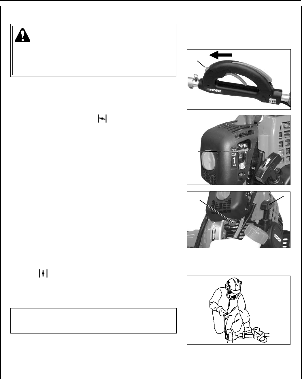
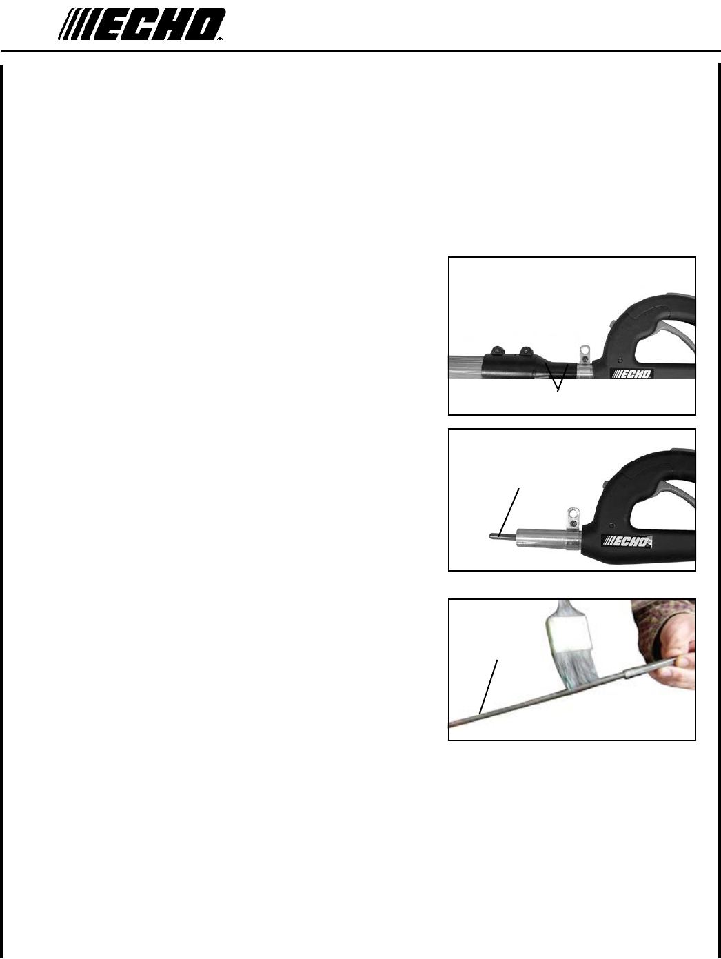
sTarTIng Cold engIne
WARNING
The attachment will operate immediately when the engine starts,
and could result in possible serious injury. Keep movable parts of
the attachment away from objects that could become entangled or
thrown, and surfaces that could cause loss of control.
1. Stop Switch
Move stop switch button (A) forward away from the STOP
position.
2. Choke
Move choke (B) to “Cold Start” ( ) Position.
3. Purge Bulb
Pump purge bulb (C) until fuel is visible and ows freely in the
clear fuel tank return line. Pump bulb an additional 4 or 5 times.
4. Recoil Starter
Lay the unit on a at, clear area, and keep movable attachment
parts clear of all obstacles. Firmly grasp throttle handle and throttle
trigger lockout with left hand and fully depress throttle trigger to
wide open position. Rapidly pull recoil starter handle/rope (D)
until engine res (or maximum ve [5] pulls).
5. Choke
After engine res (or ve [5] pulls), move choke lever back to
“Run” ( ) position. Hold throttle trigger and throttle trigger
lockout fully depressed and pull recoil starter handle/rope until en-
gine starts and runs. Release throttle trigger and allow unit to warm
up at idle for several minutes.
NOTE
If engine does not start with choke in “Run” position after 5 pulls,
repeat instructions 2 - 5.
6. After engine warms up, gradually depress throttle trigger to in-
crease engine RPM to operating speed.
A
CD
B
20
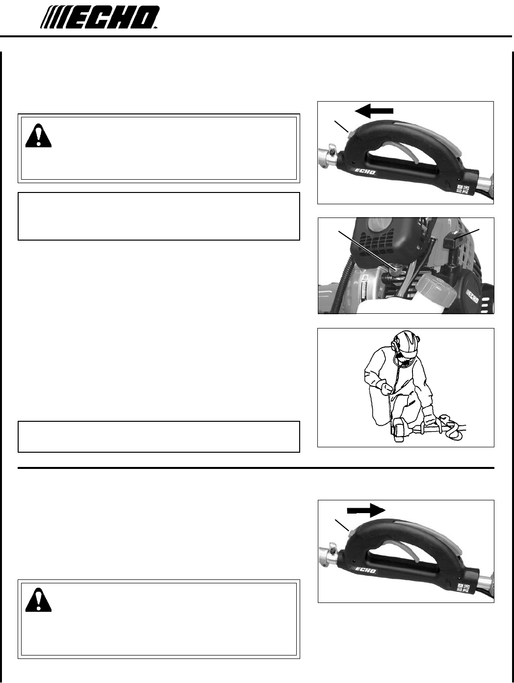
sTarTIng warm engIne
The starting procedure is the same as Cold Start except DO NOT close
the choke, and do not depress throttle trigger to wide open position.
WARNING
The attachment should not move at idle, otherwise serious personal
injury may result.
NOTE
If attachment moves, readjust carburetor according to “Carburetor
Adjustment” instructions in this manual or see your ECHO Dealer.
1. Stop Switch.
Move Stop Switch button (A) forward away from the STOP posi-
tion.
2. Purge Bulb
Pump purge bulb (C) until fuel is visible and ows freely in the
clear fuel tank return line. Pump bulb an additional 4 or 5 times.
3. Recoil Starter.
Lay the unit on a at, clear area, and rmly grasp right hand grip
with left hand. Do not depress throttle trigger. Pull the recoil
starter handle (D) until the engine res.
NOTE
If engine does not start after 5 pulls, use Cold Start Procedure.
sToppIng engIne
1. Throttle.
Release throttle trigger, and allow engine to return to idle before
stopping engine.
2. Stop Switch.
Move stop switch button (A) backward to STOP position.
WARNING
If engine does not stop when stop switch is moved to STOP posi-
tion, close choke - COLD START position - to stall engine. Have
your ECHO dealer repair stop switch before using pruner again.
A
CD
A
Power PrunerTM
oPeraTor's Manual 21
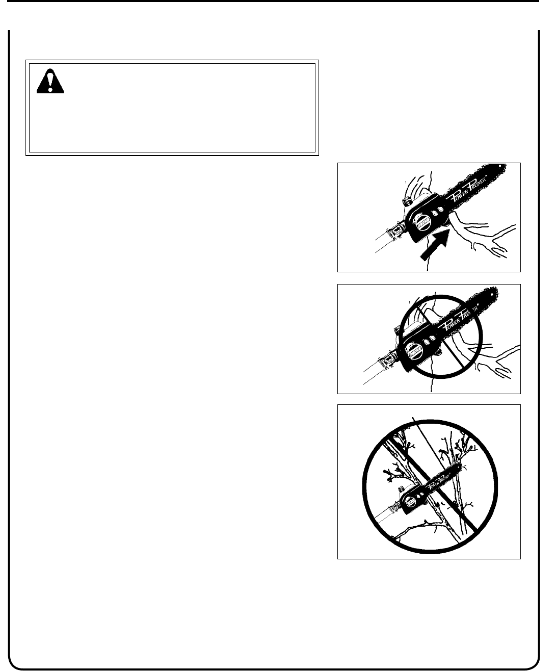
prunIng TeChnIques
WARNING
Engine exhaust IS HOT, and contains Carbon Monoxide (CO), a
poison gas. Breathing CO can cause unconsciousness, serious in-
jury, or death. Exhaust can cause serious burns. ALWAYS position
unit so that exhaust is directed away from your face and body.
The Power PrunerTM is designed for light to medium trimming of limbs
and branches up to 203 mm (8 in.) in diameter. Follow these tips for
successful operation.
• Plan cut carefully. Check direction branch will fall.
• Plan retreat path from falling branch. Cut branches bounce when
striking ground.
• Long branches should be removed in several pieces.
• Do not stand directly beneath branch being cut.
• When ready to cut:
Hold "cutting shoe" against branch. This will prevent whipping of the
branch. DO NOT use back and forth sawing action.
• Look out for branch immediately behind the branch being cut. If saw
chain hits rear branch damage to saw chain may occur.
• Accelerate to full throttle.
• Apply cutting pressure.
• Ease cutting pressure when nearing end of cut to maintain control.
• When pruning a limb 102 mm (4 in.) diameter or larger, cut as fol-
lows:
1. Under cut 1/4 limb diameter near tree trunk.
2. Finish top cut slightly farther out on limb.
3. Flush cut stub at trunk.
• DO NOT use for felling or bucking.
CorreCT
guIde agaInsT
branCh
blade hITs rear branCh
noT
CorreCT
noT
CorreCT

22
Your ECHO Power PrunerTM is designed to provide many hours of trouble free service. Regular scheduled maintenance
will help your pruner achieve that goal. If you are unsure or are not equipped with the necessary tools, you may want to
take your unit to an ECHO Service Dealer for maintenance. To help you decide whether you want to DO-IT-YOUR-
SELF or have the ECHO Dealer do it, each maintenance task has been graded. If the task is not listed see your ECHO
Dealer for repairs.
skIll level
Level 1 = Easy to do. Common tools may be required.
Level 2 = Moderate difculty. Some specialized tools may be required.
ECHO offers REPOWERTM Maintenance Kits and Parts to make your maintenance job easier.
maInTenanCe InTervals
WARNING
Moving parts can amputate ngers or cause severe injuries. Keep hands, clothing and loose objects away from all
openings. Always stop engine, disconnect spark plug, and make sure all moving parts have come to a complete
stop before removing obstructions, clearing debris, or servicing unit. Allow unit to cool before performing service.
Wear gloves to protect hands from sharp edges and hot surfaces.
maInTenanCe
COMPONENT / SYSTEM MAINTENANCE
PROCEDURE
REQ'D
SKILL
LEVEL
DAILY OR
BEFORE
USE
EVERY
REFUEL 3 MONTHS YEARLY
Air Filter Inspect/Clean 1I / C * R *
Choke Shutter Inspect/Clean 1I / C
Fuel Filter Inspect/Replace 1I * I / R *
Fuel Cap Gasket Inspect/Replace 1I * R *
Fuel System Inspect/Replace 1I (2) * I (2) *
Spark Plug Inspect/Clean/Replace 1I/C/R *
Cooling System Inspect/Clean 2I / C
Muffler Spark Arrestor Inspect/Clean/Replace 2I/C/R *
Cylinder Exhaust Port Inspect/Clean/Decarbon 2I / C
Drive Shaft (Flex Cable
Models)
Inspect/Grease 2I (1)
Guide Bar / Sprocket Nose Inspect/Clean/Lubricate 2I / C * I
Saw Chain Inspect/Sharpen/
Replace/Tension 2I * I *
Recoil Starter Rope Inspect/Clean 1I / C *
Screws/Nuts/Bolts Inspect/Tighten/Replace 1I *
(2) Low evaporative fuel tanks DO NOT require regular maintenance to maintain emission integrity.
* All recommendations to replace are based on the finding of damage or wear during inspection.
MAINTENANCE PROCEDURE LETTER CODES: I = INSPECT, R = REPLACE, C = CLEAN
IMPORTANT NOTE - Time intervals shown are maximum. Actual use and your experience will determine the
frequency of required maintenance.
MAINTENANCE PROCEDURE NOTES:
(1) Apply grease every 25 hours of use.
Power PrunerTM
oPeraTor's Manual 23
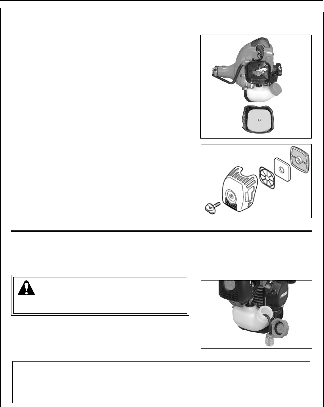
aIr fIlTer
Level 1.
Parts required: REPOWERTM AIR & FUEL FILTER KIT.
1. Close choke (cold start position). This prevents dirt from entering
the carburetor throat when the air lter is removed. Brush accumu-
lated dirt from air cleaner area.
2. Remove air lter cover and air lter retainer from inside cover.
Brush dirt from inside cover.
3. Replace lter if it is damaged, very dirty, or the rubber sealing
edges are deformed.
4. Remove foam pre-lter and air lter and clean as indicated below:
Foam Pre-lter
• Clean foam lter in water/detergent solution and rinse with clean
water.
• Wrap the lter in a clean, dry cloth and squeeze (do not wring) dry.
Allow to dry completely before reuse. Do not oil.
Dual Layer Air Filter
• Lightly brush debris from lter.
• Soak heavily soiled lters in water/detergent solution to loosen dirt,
then brush lightly.
• Rinse with clean water and allow to dry completely before reuse.
5. Place foam pre-lter over raised center and inside outer lip of air
lter. Install air lter in air lter case.
6. Install air lter retainer on post in air lter cover, at side up.
7. Install air lter cover and tighten cover knob securely.
fuel fIlTer
Level 1.
Parts required: REPOWERTM AIR & FUEL FILTER KIT.
DANGER
Fuel is VERY ammable. Use extreme care when mixing, storing
or handling, or serious personal injury may result.
1. Use a clean rag to remove loose dirt from around fuel cap and
empty fuel tank.
2. Use the “fuel line hook” to pull the fuel line and lter from the
tank.
3. Remove the lter from the line and install the new lter.
NOTE
Federal EPA regulations require all model year 2012 and later gasoline powered engines produced for sale in the
United States to be equipped with a special low permeation fuel supply hose between the carburetor and fuel tank.
When servicing model year 2012 and later equipment, only fuel supply hoses certied by EPA can be used to replace
the original equipment supply hose. Fines up to $37,500 may be enforced for using an un-certied replacement part.
24
0.65 mm
(0.026 in.)
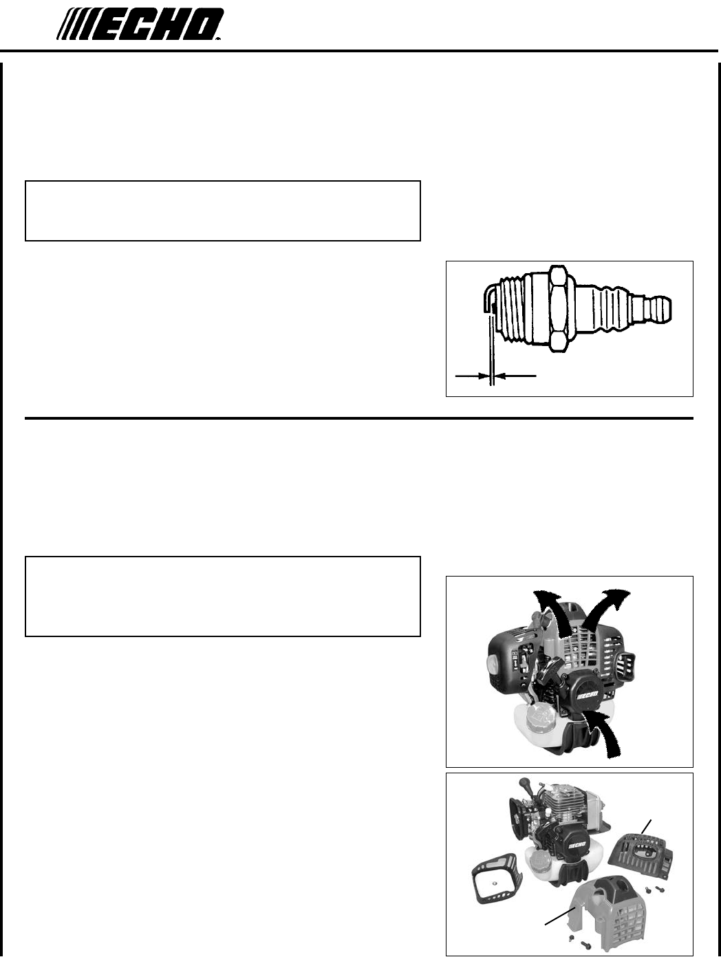
spark plug
Level 2.
Parts Required: REPOWERTM Tune-Up Kit
IMPORTANT
Use only NGK BPM-8Y spark plug (BPMR-8Y in Canada)
otherwise severe engine damage may occur.
1. Remove spark plug and check for fouling, worn and rounded
center electrode.
2. Clean the plug or replace with a new one. DO NOT sand blast to
clean. Remaining sand will damage engine.
3. Adjust spark plug gap by bending outer electrode.
4. Tighten spark plug to 150-170 kgf • cm (130-150 in • lbf).
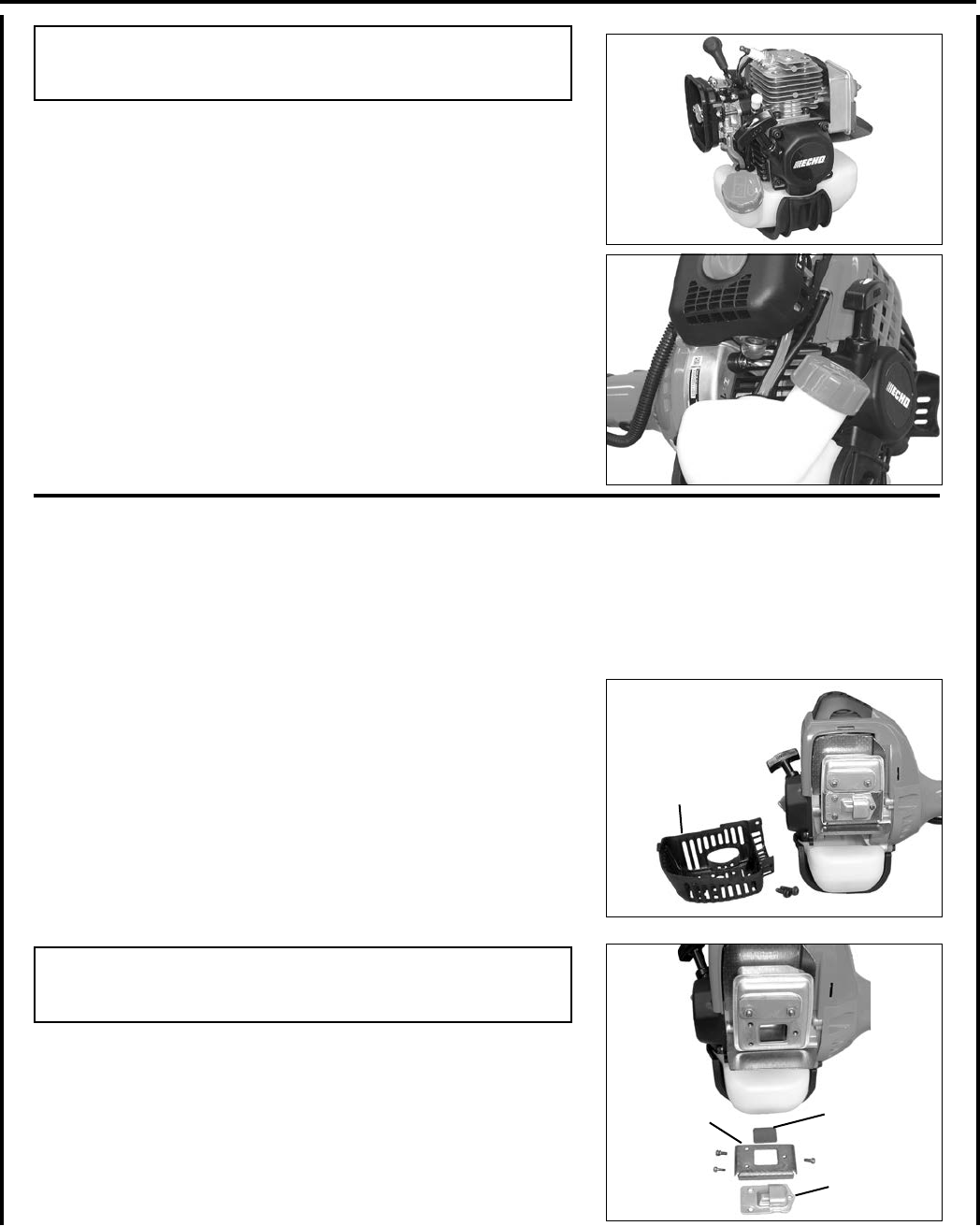
CoolIng sysTem
Level 2.
Parts Required: None if you are careful.
IMPORTANT
To maintain proper engine operating temperatures, cooling air
must pass freely through the cylinder n area. This ow of air
carries combustion heat away from the engine.
Overheating and engine seizure can occur when:
• Air intakes are blocked, preventing cooling air from reaching the
cylinder.
• Dust and grass build up on the outside of the cylinder. This build up
insulates the engine and prevents the heat from leaving.
Removal of cooling passage blockages or cleaning of cooling ns is
considered “Normal Maintenance.” Any failure attributed to lack of
maintenance is not warranted.
1. Remove spark plug lead.
2. Remove air cleaner cover.
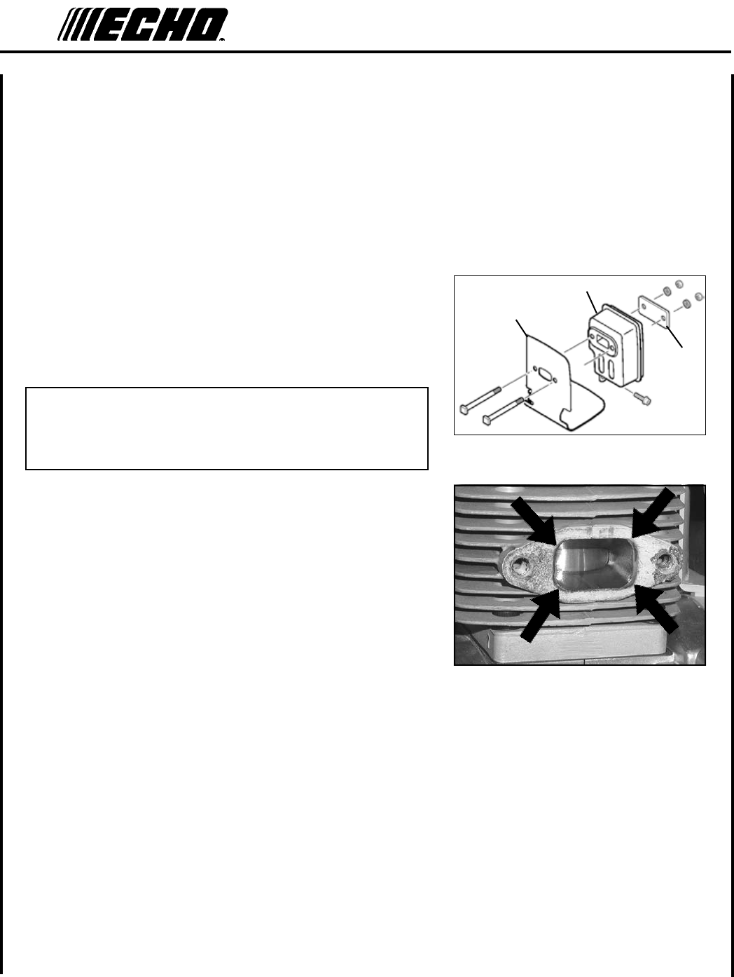
3. Remove mufer cover (A).
4. Remove engine cover (B).
A
B
Power PrunerTM
oPeraTor's Manual 25
eXhausT sysTem
Spark Arrestor Screen
Level 2.
Parts Required: Spark Arrestor Screen, Gasket
1. Remove mufer cover (A).
2. Place piston at Top Dead Center (TDC) to prevent carbon/dirt from
entering cylinder.
3. Remove spark arrestor screen (B), gasket (C), and exhaust guide
(D) from mufer body.
4. Clean carbon deposits from mufer components.
NOTE
When cleaning carbon deposit, be careful not to damage the cata-
lytic element inside mufer.
5. Replace screen if it is cracked, plugged or has holes burned
through.
6. Assemble components in reverse order.
IMPORTANT
DO NOT use a metal scraper to remove dirt from the cylinder ns.
5. Use brush to remove dirt from the cylinder ns.
6. Remove grass and leaves from the grid between the recoil starter
and fuel tank.
7. Assemble components in reverse order.
A
B
CD
26
Exhaust Port Cleaning
Level 2.
Parts Required: As needed: Heat Shield
1. Remove spark plug lead from spark plug, and remove mufer
cover.
2. Place piston at top dead center. Remove mufer (A), heat shield
(B), and eyeplate (C).
3. Use a wood or plastic scraping tool to clean deposits from cylinder
exhaust port.
IMPORTANT
Never use a metal tool to scrape carbon from the exhaust port.
Do not scratch the cylinder or piston when cleaning the exhaust
port. Do not allow carbon particles to enter the cylinder.
4. Inspect heat shield, and replace if damaged.
5. Install heat shield, mufer, and eyeplate.
6. Tighten mufer mounting bolts (or nuts) to 53-70 in•lbf
(60-80 kgf•cm).
7. Install mufer cover and attach spark plug lead.
8. Start engine, and warm to operating temperature.
9. Stop engine, and re-tighten mounting bolts (or nuts) to specica-
tions.
B
A
C
Power PrunerTM
oPeraTor's Manual 27
CarbureTor adjusTmenT
Engine Break-In
New engines must be operated a minimum duration of two tanks of fuel
break-in before carburetor adjustments can be made. During the break-
in period your engine performance will increase and exhaust emissions
will stabilize. Idle speed can be adjusted as required.
High Altitude Operation
This engine has been factory adjusted to maintain satisfactory starting,
emission, and durability performance up to 1,100 feet above sea level
(ASL) (96.0 kPa). To maintain proper engine operation and emission
compliance above 1,100 feet ASL the carburetor may need to be ad-
justed by an authorized ECHO service dealer.
IMPORTANT
If the engine is adjusted for operation above 1,100 feet ASL, the
carburetor must be re-adjusted when operating the engine below
1,100 feet ASL, otherwise severe engine damage may result.
Level 2.
Parts required: None
NOTE
Every unit is run at the factory and the carburetor is set in compli-
ance with emission regulations. Carburetor adjustments, other than
idle speed, must be performed by an authorized ECHO dealer.
1. Check idle speed and reset if necessary. If a tachometer is avail-
able, idle speed screw (A) should be set to the specications found
on "Specications" page of this manual. Turn idle screw (A)
clockwise to increase idle speed; counter clockwise to decrease
idle speed.
WARNING
When carburetor adjustment is completed, the cutting attachment
should not turn at idle, otherwise serious personal injury may
result.
A
28
lubrICaTIon
Flexible Drive Shaft
Level 1.
Parts required: POWER BLENDXTM 14 oz. or Lithium Based
Grease.
1. Loosen clamping screws (A) on driveshaft coupling.
2. Remove handle and exible drive shaft.
3. Remove exible drive shaft (B).
4. Wipe ex shaft clean and apply a thin coating of grease.
5. Slide ex shaft into handle. Leave 2 - 3 inches of ex shaft ex-
posed. DO NOT get dirt on ex shaft.
6. Align exible drive shaft with drive shaft socket, and slide together
until handle is fully seated into drive shaft coupling.
7. Tighten clamping screws (A).
A
B
B
Power PrunerTM
oPeraTor's Manual 29
E
A
C
DB
guIde bar and saw ChaIn replaCemenT
WARNING
Never try to replace or adjust guide bar and saw chain with engine running. Always disconnect spark plug wire
before servicing guide bar and saw chain. This saw chain is VERY sharp, wear heavy gloves to protect your hands
when handling it. Wear eye protection meeting CE or ANSI specication Z87.1.
Guide Bar Replacement / Installation
Level 2
1. Remove two (2) guide bar nuts (A), and unscrew sprocket cover
screw (B).
2. Remove sprocket cover (D).
3. Remove guide bar and saw chain from gear case and sprocket.
4. Remove chain from guide bar and check guide bar for damage and
excessive or uneven wear. Replace guide bar if necessary.
5. Install chain on guide bar with cutters on top of bar facing toward
bar tip.
6. Install guide bar and chain on gear case, engaging chain with drive
sprocket (E).
7. Turn tension adjustment screw (C) to ensure chain tension adjuster
pin ts into the guide bar adjuster hole.
8. Install sprocket cover (D), tighten guide bar nuts (A) nger tight,
and fasten sprocket cover screw (B).
9. Adjust chain tension.
30
a
C
A
C
DB
Sprocket Cover Cleaning
1. Remove two (2) guide bar nuts (A), and unscrew sprocket cover
screw (B).
2. Remove sprocket cover (D).
3. Gently brush debris from inside sprocket cover and from around
sprocket.
4. Turn tension adjustment screw (C) to ensure chain tension adjuster
pin ts into the guide bar adjuster hole.
5. Install sprocket cover (D), tighten guide bar nuts (A) nger tight,
and fasten sprocket cover screw (B).
6. Adjust chain tension.
5. Tighten both guide bar nuts with nose held up. Tighten rear nut
rst.
6. Pull the chain around the guide bar by hand. Reduce the chain
tension if you feel tight spots.
7. When chain is properly tensioned, tighten guide bar nuts securely.
IMPORTANT
Tighten guide bar nuts to 8 - 9 N•m (71 - 80 in. lbs.) DO NOT
over-tighten nuts. Damage may result.
8. Keep chain properly tensioned at all times.
NOTE
All chains require frequent adjustment.
9. Connect spark plug lead.
To Adjust Saw Chain Tension
WARNING
Always disconnect spark plug wire before servicing cutting attach-
ment. Wear gloves when handling saw chain, otherwise serious
personal injury may result.
To Adjust Saw Chain Tension
1. Move stop switch to STOP position.
2. Disconnect spark plug lead.
3. Loosen two guide bar nuts (A) until nger tight.
IMPORTANT
Always loosen guide bar nuts before turning the chain tension ad-
juster, otherwise the clutch cover and tensioner will be damaged.
4. Hold the bar nose up, and turn the adjuster screw (B) clockwise un-
til the chain ts snugly against the underside of the bar, as shown.
Cold Chain Only - turn adjuster screw CW an additional 1/8 - 1/4
turn.

Power PrunerTM
oPeraTor's Manual 31
IMPORTANT
Check bar Part Number on your Power Pruner. Chain and guide bar gauge size must be identical. Use Bar/Chain
combinations shown in table above.
Power Pruner B&C Combinations
Bar P/N Chain P/N Chain Type Links Pitch Gauge
Narrow Kerf
10" narrow bar P/N
10A4CD3739 90S39CQ 90 39 3/8" 0.043
12" narrow bar P/N
12A4CD3744 90S44CQ 90 44 3/8" 0.043
Regular
10" regular bar P/N
10A0CD3739 91VXL39CQ 91 39 3/8" 0.050
12" regular bar P/N
12A0CD3744 91VXL44CQ 91 44 3/8" 0.050
32
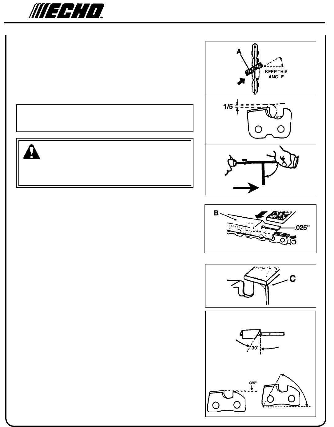
fIlIng saw ChaIn
Level 2.
IMPORTANT
Dull or damaged cutters will result in poor cutting performance,
increased vibration, and premature saw chain failure.
WARNING
Always stop engine and disconnect spark plug wire before servic-
ing guide bar and saw chain. Always wear gloves when ling saw
chain, otherwise serious personal injury may result.
1. Set round le (A) in cutter at 30° angle. One fth (1/5) of the le
should be exposed above top cutter edge.
2. Keep le horizontal in cutter and le in one direction.
3. File until cutter top and side bevel edges are sharp without nicks.
4. Place depth gauge tool (B) rmly on top of cutter with .025 in. slot
end against front cutter raker. File cutter raker with at le until
ush with top of depth gauge.
5. Finish cutter sharpening by rounding front raker edge (C) with at
le.
6. Properly led cutter is as shown.
7. Apply clean oil and rotate saw chain slowly to wash away lings.
8. If saw chain is coated or clogged with resin, clean in kerosene,
then soak in oil.
1
2
3
4
5
30°
90°
(TOP PLATE ANGLE)
(DEPTH GAUGE)
(TOP PLATE CUTTING ANGLE)
6
55°

Power PrunerTM
oPeraTor's Manual 33
TroubleshooTIng
DANGER
Fuel vapors are extremely ammable and may cause re and/or explosion. Never test for ignition spark by ground-
ing spark plug near cylinder plug hole, otherwise serious personal injury may result.
TRAHCGNITOOHSELBUORTMELBORPENIGNE
melborPkcehCsutatSesua
Cy
demeR
enignE
-sknarc
/drahstrats
t'nseod
trats
roterubractaleuFroterubractaleufoNdeggolcreniartsleuF
deggolcenilleuF
roterubraC
ecalperronaelC
ecalperronaelC
relaedohcEruoyeeS
rednilyctaleuFrednilyctaleufoNroterubra
Cr
elaedohcEruoyeeS
leufhtiwtewrelffuMhcirooterutxiMleu
Fe
kohcnepO
retlifriaecalper/naelC
roterubractsujdA
relaedohcEruoyeeS
dnetakrapS
eriwgulpfo
krapsoNffohctiwspotS
melborplacirtcelE
hctiwskcolretnI
NOothctiwsnruT
relaedohcEruoyeeS
relaedohcEruoyeeS
gulptakrapSkrapsoNtcerrocnipagkrapS
nobrachtiwderevoC
leufhtiwdeluoF
evitcefedgulP
).ni620.0(mm56.ottsujdA
ecalperronaelC
ecalperronaelC
gulpecalpeR
,snurenignE
roseidtub
tonseod
etarelecca
ylreporp
retlifriAytridretlifriAraewlamro
Ne
calperronaelC
retlifleuFytridretlifleu
Fs
eudiser/stnanimatnoCni
leuf
ecalpeR
tnevleuFdeggulptnevleu
Fn
iseudiser/stnanimatnoC
leuf
ecalperronaelC
gulPkrapSnrow/ytridgulPraewlamro
Ne
calperrotsujdadnanaelC
roterubraCtnemtsujdareporpmInoitarbi
Vt
sujdA
metsySgnilooCmetsysgnilooC
deggulp/ytrid
ninoitarepodednetxE
snoitacolytsud/ytrid
naelC
rotserrAkrapS
neercS
rotserrakrapS
deggulpneercs
raewlamro
Ne
calpeR
seodenignE
knarcton
A/NA/Nmelborpenignelanretn
Ir
elaedohcEruoyeeS
34
2. Place the stop switch in the "OFF" position.
3. Remove accumulation of grease, oil, dirt and debris
from exterior of unit.
IMPORTANT
Some tree sap and resins are corrosive. Thoroughly
wash the guide bar and sprocket areas after each use,
then coat metal parts with light oil.
4. Perform all periodic lubrication and services that are
required.
5. Tighten all the screws and nuts.
6. Drain fuel tank completely. Press purge bulb 6 -7
times to remove remaining fuel from carburetor then
drain the tank again. Close choke, start and run the
engine until it stops due to lack of fuel.
sTorage
WARNING
During operation the mufer or catalytic mufer and surrounding cover become hot. Always keep exhaust area clear
of ammable debris during transportation or when storing, otherwise serious property damage or personal injury
may result.
Long Term Storage (over 30 days)
Do not store your unit for a prolonged period of time (30 days or longer) without performing protective storage mainte-
nance which includes the following:
1. Store unit in a dry, dust free place, out of the reach of children.
DANGER
Do not store in enclosure where fuel fumes may accumulate or reach an open ame or spark or serious personal
injury may result.
7. A. Allow engine to cool then remove the spark
plug and pour 7 cc (1/4 oz.) of fresh, clean, two
stroke engine oil into the cylinder through the
spark plug hole.
B. Pull the recoil starter handle 2-3 times to
distribute the oil inside the engine.
C. Observe the piston location through the spark
plug hole. Pull the recoil starter handle slowly
until the piston reaches the top of its travel and
leave it there.
8. Install the spark plug (do not connect spark plug
cable).
9. Install the guide bar cover on the guide bar and saw
chain during storage.

Power PrunerTM
oPeraTor's Manual 35
speCIfICaTIons
MODEL ---------------------------------------------------- PPT-280
Length (Standard) ------------------------------------------ 2.86 m (9 ft. 5 in.)
Length (Extended) ----------------------------------------- 4.01 m (13 ft. 2 in.)
Length w/extension ---------------------------------------- 5.23 m (17 ft. 2 in.)
Width -------------------------------------------------------- .25 m (9.69 in.)
Height ------------------------------------------------------- .25 m (9.69 in.)
Weight (dry) ------------------------------------------------ 8.7 kg (19.25 lb.)
Engine Type ------------------------------------------------ Air cooled, two-stroke, single cylinder gasoline engine
Bore ---------------------------------------------------------- 34.0 mm (1.34 in.)
Stroke -------------------------------------------------------- 31.0 mm (1.22 in.)
Displacement ----------------------------------------------- 28.1 cc (1.71 cu. in.)
Exhaust System -------------------------------------------- Spark arrestor mufer or spark arrestor mufer with catalyst
Carburetor--------------------------------------------------- Diaphragm model
Spark Plug -------------------------------------------------- NGK BPM-8Y Gap 0.65 mm (0.026 in.)
Fuel ---------------------------------------------------------- Mixed (Gasoline and Two-stroke Oil)
Fuel/Oil Ratio ---------------------------------------------- 50 : 1 Power Blend X™ ISO-L-EGD (ISO/CD 13738) and
J.A.S.O. M345- FD, two-stroke, air-cooled engine oil.
Gasoline ----------------------------------------------------- Use 89 Octane unleaded. Do not use fuel containing methyl
alcohol, more than 10% ethyl alcohol or 15% MTBE. Do not use
alternative fuels such as E-15 or E-85.
Oil ------------------------------------------------------------ Power Blend X TM Premium Universal 2-Stroke Oil
Fuel Tank Capacity ---------------------------------------- 0.62 lit. (21.1 US . oz.)
Starter System ---------------------------------------------- Automatic Recoil Starter
Clutch-------------------------------------------------------- Centrifugal Type
Sprocket Type ---------------------------------------------- 6 tooth spur, 9.53 mm (3/8 in.) pitch
Power Transmission Shaft Assembly ------------------- Aluminum Extrusion
Gear Case Ratio -------------------------------------------- 1.5:1
Oiling System ---------------------------------------------- Automatic
Saw Chain Oil Capacity ---------------------------------- 225 ml (7.6 oz.)
Handle ------------------------------------------------------- Right hand grip w/throttle trigger and lockout
Shoulder Harness ------------------------------------------ Standard
Idle Speed (RPM) ------------------------------------------ 2,800
Clutch Engagement Speed (RPM) ----------------------- 4,300
Wide Open Throttle Speed (RPM) ---------------------- 10,700
Guide Bar and Saw Chain (91) -------------------------- 305 mm (12 in.); 9.53 mm (3/8 in.) pitch, 0.050 gauge

36
warranTy sTaTemenTs
ECHO LIMITED WARRANTY STATEMENT FOR
PRODUCT SOLD IN USA AND CANADA BEGINNING 01/01/2010
ECHO'S RESPONSIBILITY
ECHO Incorporated’s Limited Warranty, provides to the original purchaser that this ECHO product is free from defects in material and workmanship.
Under normal use and maintenance from date of purchase, ECHO agrees to repair or replace at ECHO’s discretion, any defective product
free of charge at any authorized ECHO servicing dealer within listed below application time periods, limitations and exclusions. THIS LIMITED
WARRANTY IS ONLY APPLICABLE TO ECHO PRODUCTS SOLD BY AUTHORIZED ECHO DEALERS. IT IS EXTENDED TO THE ORIGINAL
PURCHASER ONLY, AND IS NOT TRANSFERABLE TO SUBSEQUENT OWNERS EXCEPT FOR EMISSION RELATED PARTS. Repair
parts and accessories replaced under this warranty are warranted only for the balance of the original unit or accessory warranty period. Any
damage caused by improper installation or improper maintenance is not covered by this warranty. All parts or products replaced under warranty
become the property of ECHO, Inc. This warranty is separate from the Emission control warranty statement supplied with your new product.
Please consult the Emission Control Warranty Statement for details regarding emission related parts. For a list of Authorized ECHO Dealers
refer to WWW.ECHO-USA.COM or call 1-800-432-ECHO.
OWNER’S RESPONSIBILITY
To ensure trouble free warranty coverage it is important that you register your ECHO equipment on-line at WWW.ECHO-USA.COM-
The owner shall demonstrate reasonable care and use, and follow preventative maintenance, storage, fuel and oil usage as prescribed in the
dealer for warranty repairs (within the applicable warranty period), and arrange for pick-up or return of your unit after the repairs have been
made. For your nearest authorized ECHO servicing dealer, call ECHO’s Dealer Referral Center, at 1-800-432-ECHO or you can locate an ECHO
servicing dealer at WWW.ECHO-USA.COM. Should you require assistance or have questions concerning ECHO’s Warranty Statement, you
can contact our Consumer Product Support Department at 1-800-673-1558 or contact us through the web at WWW.ECHO-USA.COM.
PRODUCT WARRANTY PERIOD
RESIDENTIAL APPLICATION
5 YEAR WARRANTY - All units for residential, or non-income producing use will be covered by this limited warranty for ve (5) years from
date of purchase.
EXCEPTIONS:
are warranted for the life* of the product on parts only.
producing use will be covered for failures due to defects in material or workmanship for a period of 60 days from original product
purchase date. Any misuse from contact with concrete, rocks, or other structures is not covered by this warranty.
manual for string head installation and maintenance instructions.
COMMERCIAL APPLICATION
1 YEAR WARRANTY - All Chain Saws, QuikVent Saws, and Cut-Off Saws for commercial, institutional, agricultural, industrial, or income
producing use will be covered by this limited warranty for one (1) year from the date of purchase.
2 YEAR WARRANTY - All other units for commercial, institutional, agricultural, industrial, or income producing use will be covered by this
limited warranty for two (2) years from the date of purchase.
EXCEPTIONS:
are warranted for the life* of the product on parts only.
agricultural, industrial, rental, or income producing will be covered for failures due to defects in material or workmanship for a period
of 30 days from original product purchase date. Any misuse from contact with concrete, rocks, or other structures is not covered by
this warranty.
manual for string head installation and maintenance instructions.
RENTAL APPLICATION - 90 DAYS WARRANTY
* section of
this warranty statement for “Life”

Power PrunerTM
oPeraTor's Manual 37
PURCHASED REPAIR PARTS, SHORT BLOCKS AND ACCESSORIES
ATTENTION TWO-STROKE ENGINE POWER PRODUCT OWNERS
This ECHO two-stroke engine power product is a quality-engineered unit which has been manufactured to exact tolerances to provide superior
performance. To help ensure the performance of the unit, it is required to use two-stroke oil which meets the ISO-L-EGD Standard per ISO/CD
13738 and JASO M345FD Standards. ECHO Power Blend™ Two-Stroke Oil
L-EGD (ISO/CD 13738) and JASO M345FD Standards. The use of two-stroke oils designed for other applications, such as for outboard motors
or lawnmowers can result in severe engine damage, and will void your two-stroke engine limited warranty.
THIS WARRANTY DOES NOT COVER DAMAGE CAUSED BY:
that do not meet the ISO-L-EGD (ISO/CD 13738) and JASO M345FD
Standards. Engine problems due to inadequate lubrication caused by failure to use an ISO-L-EGD compliant and JASO M345FD registered
oil, will void the two-stroke engine limited warranty. meets the ISO-L-EGD and JASO M345FD
Standard. Emission related parts are covered for 5 years residential use or 2 years commercial use regardless of two-stroke oil used, per
the statement listed in the EPA or California Emission Defect Warranty Explanation.
. Only use gasoline which
contains . Gasohol which contains a maximum
is also approved. The prescribed mixing ratio of gasoline to oil is listed on the ECHO oil label and covered in your operator’s manual.
engine speeds as listed in your operator’s manual.
of unauthorized attachments.
manual. Preventative maintenance as outlined in the operators manual is the customer’s responsibility.
warranty period.
parts and other items are not warranted, including but not limited to: lubricants, starter cords, and engine tune-ups.
Manuals.
screen.
with recommended grease or oil change intervals.
® beyond recommended capacity.
failure occur, the product should not be used, but delivered as is to an authorized ECHO servicing dealer.
It is a dealer’s and/or customer’s responsibility to complete and return the warranty registration card supplied with your ECHO product or by visiting
WWW.ECHO-USA.COM
ECHO servicing dealer for warranty service. Proof of purchase rests solely with the customer. Some states do not allow limitations on how long
an implied warranty lasts, so the above limitations may not apply to you. Some states do not allow the exclusion or limitation of incidental or
Incorporated, 400 Oakwood Rd., Lake Zurich, IL 60047.
DISCLAIMER OF IMPLIED WARRANTIES
OR USE and any implied warranty of MERCHANTABILITY
99922201032
11/18/2011

38
noTes

Power PrunerTM
oPeraTor's Manual 39
noTes

CONSUMER PRODUCT
SUPPORT
1-800-673-1558
8:30 - 4:30 Mon - Fri C.S.T.
ECHO, INCORPORATED
400 OakwOOd ROad
Lake ZuRich, iL 60047
www.echo-usa.com
DEALER?
Call
1-800-432-ECHO
1-800-432-3246
or
www.echo-usa.com
servICIng InformaTIon
parTs/serIal number
Genuine ECHO Parts and ECHO REPOWER™ Parts and Assemblies
for your ECHO products are available only from an Authorized ECHO
Dealer. When you do need to buy parts always have the Model Num-
ber, Type and Serial Number of the unit with you. You can nd these
numbers on the engine housing. For future reference, write them in the
space provided below.
Model No. _________________SN. ___________________
servICe
Service of this product during the warranty period must be performed
by an Authorized ECHO Service Dealer. For the name and address of
the Authorized ECHO Service Dealer nearest you, ask your retailer or
call: 1-800-432-ECHO (3246). Dealer information is also available on
our Web Site. When presenting your unit for Warranty service/repairs,
proof of purchase is required.
eCho Consumer produCT supporT
If you require assistance or have questions concerning the applica-
tion, operation or maintenance of this product you may call the ECHO
Consumer Product Support Department at 1-800-673-1558 from 8:30
am to 4:30 pm (Central Standard Time) Monday through Friday. Before
calling, please know the model and serial number of your unit.
warranTy regIsTraTIon
To ensure trouble free warranty coverage it is important that you regis-
ter your ECHO equipment on-line at www.echo-usa.com or by lling
out the warranty registration card supplied with your unit. Registering
your product conrms your warranty coverage and provides a direct
link between you and ECHO if we nd it necessary to contact you.
addITIonal or replaCemenT manuals
Replacement Operator, Safety Manuals, and Parts Catalogs are available from your ECHO dealer or at www.echo-
usa.com or by contacting ECHO Inc., 400 Oakwood Road, Lake Zurich, IL 60047 (800-673-1558). Always check the
ECHO Web Site for updated information.
Safety Videos are available from your Echo dealer. A $5.00 shipping charge will be required for each video.
E08011002238/E08011999999
E08612005942/E08612999999
