Echo SRM 2305 User Manual To The 4f048a9d 8ce4 B204 9991 Bdd72cade0c0
User Manual: Echo SRM-2305 to the manual
Open the PDF directly: View PDF ![]() .
.
Page Count: 26
WARNING DANGER
READ INSTRUCTIONS CAREFULLY AND FOLLOW RULES FOR
SAFE OPERATION.
FAILURE TO DO SO COULD RESULT IN SERIOUS INJURY.
© 2005
X771-000 54 2
X771 227-540 2
ENGLISH
GB
OPERATOR’S MANUAL
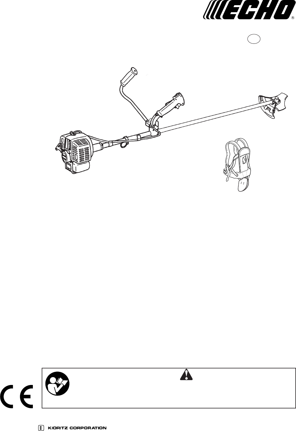
GRASS TRIMMER/
BRUSHCUTTER
SRM-2305
Printed in Japan 0512Bkf 1052 ES
2
SRM-2305
INTRODUCTION
ECHO Grass Trimmers/Brushcutters are lightweight,
high-performance, petrol engined units designed for
weed control, grass trimming and brush cutting in areas
difficult to control by any other means.
CONTENTS
Introduction ................................................................ 2
Decals and symbols................................................... 2
Rules for safe operation............................................. 3
Rules for safe operation (with metal blade) ............... 8
Rules for safe operation
(with nylon line cutting head) ................................... 10
Description ................................................................. 12
Assembling ................................................................ 13
Fuel ............................................................................ 17
Operation ................................................................... 17
Maintenance and care ............................................... 19
Trouble shooting ........................................................ 22
Storage ...................................................................... 23
Specifications ............................................................. 24
Declaration “CE” of conformity................................... 25
This Manual provides the information necessary for
assembly, operation and maintenance. You must read
this Manual to understand the safe and effective
operation of your ECHO product.
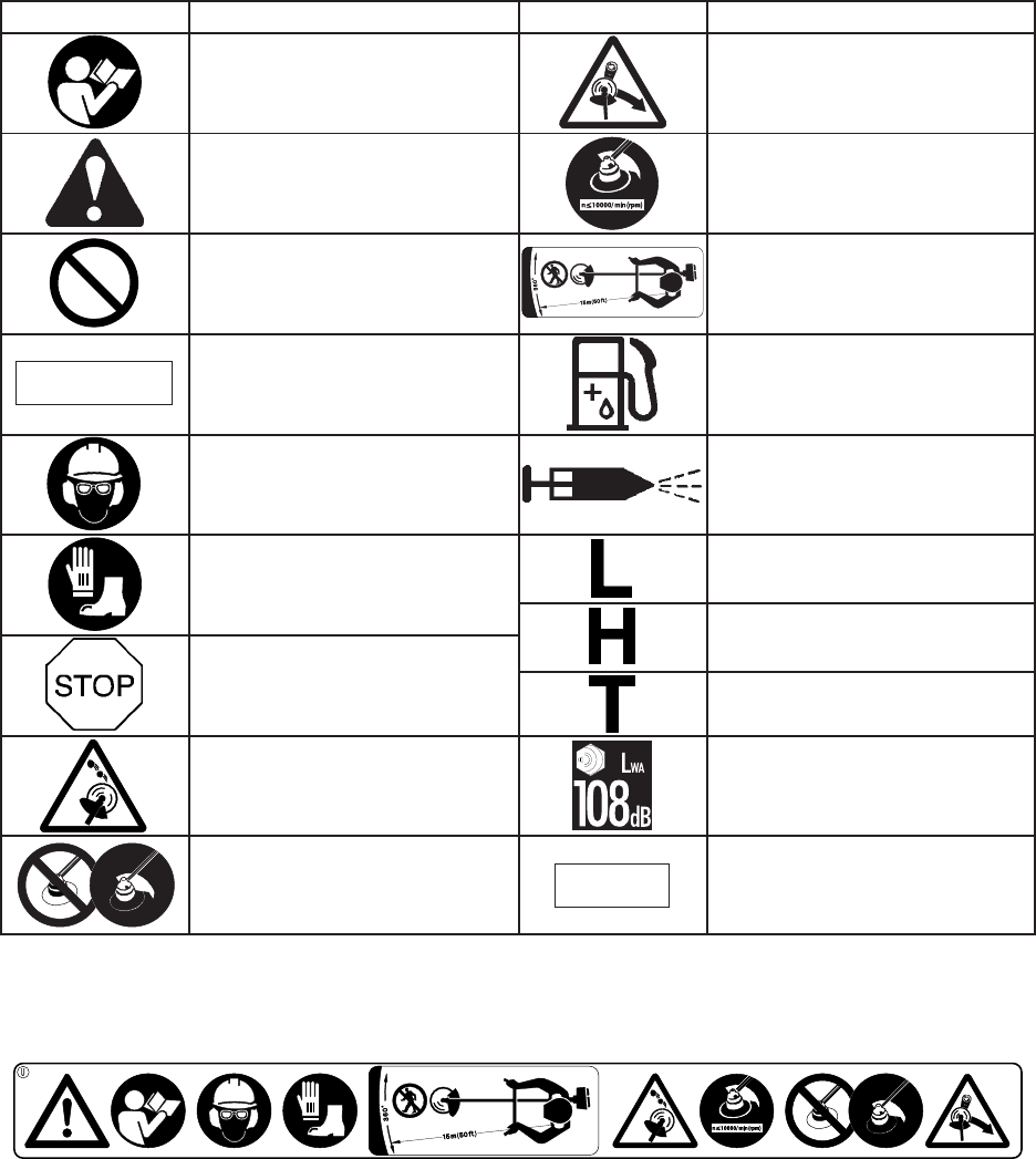
DECALS AND SYMBOLS
Carefully read the operator’s
manual
Wear eyes, ears and head
protection
Carburettor adjustment
- Low speed mixture
Purge bulb (Primer)
Petrol and oil mixture
Warning, side thrust
This symbol accompanied by the
words WARNING and DANGER
calls attentions to an act or a
condition which can lead to
serious personal injury or death.
The maximum speed of the
cutting attachment shaft in r/min
Carburettor adjustment
- High speed mixture
Symbol form/shape Symbol description/application Symbol form/shape Symbol description/application
CAUTION indicates a potentially
hazardous situation which, if not
avoided, may result in minor or
moderate injury.
Circle and slash symbol means
whatever is shown is prohibited.
Emergency stop
Keep bystanders away 15 m
Usage without shield not
permitted
Carburettor adjustment
- Idle speed
NOTE
Warning!
Thrown objects!
This enclosed message provides
tips for use, care and
maintenance of the unit.
Wear foot protection and gloves
CAUTION
Locate this safety decal on your unit. The complete unit
illustration found in the “DESCRIPTION” section will
help you locate them.
Part Number 890617-43130
Make sure the decal is legible and that you understand
and follow the instructions on it. If a decal cannot be
read, a new one can be ordered from your ECHO
dealer.
Guaranteed sound power level

3SRM-2305
RULES FOR SAFE OPERATION
TRAINING
WARNING DANGER
GRASS TRIMMERS AND BRUSHCUTTERS CAN
THROW SMALL GRAVEL, STONE, GLASS, METAL
OR PLASTIC OBJECTS AS WELL AS THE
MATERIAL BEING CUT. READ THESE “RULES
FOR SAFE OPERATION” WITH CARE. FOLLOW
INSTRUCTIONS IN THE OPERATOR’S MANUAL.
Operator’s manual
Read the Operator’s Manual carefully. Be thoroughly
familiar with the controls and proper use of the unit.
Know how to stop the unit and shut off the engine.
Know how to unhook a harnessed unit quickly.
Never allow anyone to use the unit without proper
instruction.
•If you have any questions or problems, please
contact your ECHO dealer.
Do not permit operation without proper
training and protective equipment.
EYE PROTECTION
The operator must wear eye protection not only against
objects thrown by the unit, but also because eye
infections can be caused by airborne dust, seeds and
pollen.
Prescription glasses may be worn under the safety
goggles.
Eye protection should also be worn by persons in the
risk zone which extends beyond the danger zone.
Wear eye protection
HEARING AND EAR PROTECTION
Prolonged exposure to loud noise can cause impairment
or loss of hearing.
Wear a suitable hearing protective device such as
earmuffs or earplugs to protect against objectionable or
uncomfortable loud noises.
Earmuffs Earplugs
PROTECTIVE CLOTHING
Choose trousers, shirts and jackets that fit trimly and
have no strings, frills or dangling straps which could
catch on the unit or the underbrush. Do not wear ties,
loose clothing or jewellery. Keep clothing buttoned or
zipped up and shirt tails tucked in. Secure hair so it is
above shoulder length.
The wearing of gloves offers some protection against
contact with skin irritants such as poison ivy. Soft
leather work gloves may also improve your grip.
ADDITIONAL PROTECTION
Hay fever (Rhinitis) sufferers may wear disposable
masks to help reduce the intake of allergenic particles.
Safety goggles
Hearing protectors Head and face protection
Shoulder harness
Trim-fitting clothes
Safety gloves
Sturdy shoes or boots
Long trousers
4
SRM-2305
a) Slide suspension point up and down the tube to find
the right balance. Rotate the clamp to level the
cutting attachment and shield. Lock in position. If the
suspension point is a free-spinning type, the unit may
tend to roll over sideways, however, you should still
level the attachment and shield on the front-to-rear
axis.
b) Balancing and levelling, as above, may require
relocation of the clamp and readjustment of the
harness straps. Also, each type of cutting attachment
and shield mounted on the unit may require
balancing.
NOTE
A person’s size can affect the balancing adjustment.
Also the balancing procedure may not work with
some ECHO units on some persons. If the procedure
does not work for you, please ask your ECHO
servicing dealer for assistance.
WARNING DANGER
ECHO TRIMMERS AND BRUSHCUTTERS ARE
DESIGNED TO FIT A WIDE VARIETY OF BODY
SIZES, BUT MAY NOT BE ADJUSTABLE FOR
EXTREMELY TALL PERSONS.
DO NOT USE THE UNIT IF YOUR FEET CAN
REACH THE CUTTING ATTACHMENT WHEN THE
UNIT IS ATTACHED TO THE HARNESS.
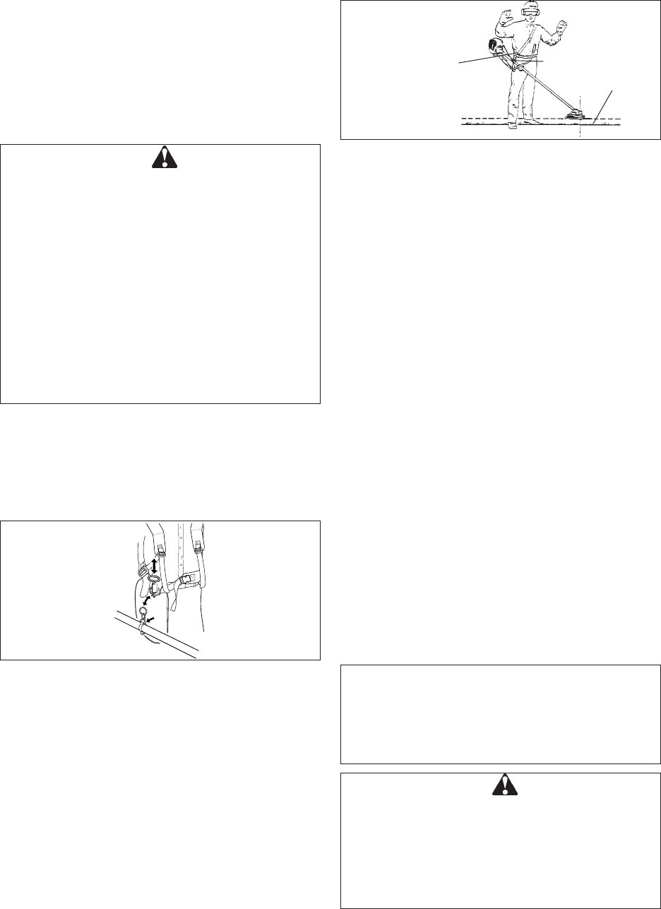
PREPARATION
Use a shoulder harness when provided or when recom-
mended in this manual. Adjust both harness and the
suspension point on the unit so the unit hangs with the
cutting attachment a few centimetres above ground
level. The cutting attachment and shield should be level
in all directions. Harness the unit on the right side as
shown.
WARNING DANGER
IN ADDITION TO HEAD, EYE AND EAR PROTEC-
TION WEAR PROTECTIVE CLOTHES, SAFETY
GLOVES AND SHOES TO PROTECT YOUR FEET
AND BODY FROM THROWN OBJECTS, AND
IMPROVE YOUR FOOTING ON SLIPPERY
SURFACES. DO NOT WEAR TIES, JEWELLY, OR
LOOSE, DANGLING CLOTHING WHICH COULD
BE CAUGHT IN THE UNIT. DO NOT WEAR OPEN-
TOED FOOTWEAR, OR GO BARE-FOOT OR
BARELEGGED. IN CERTAIN SITUATIONS, TOTAL
FACE AND HEAD PROTECTION MAY BE
REQUIRED. FOR HEAVY BRUSH CUTTING WITH
METAL BLADE, LOGGER’S TROUSERS OR LEG
CHAPS WITH PROTECTIVE INSERTS ARE ADDED
CONSIDERATIONS.
Harness quick-
release pin
Balance tool for
a level plane of
cutting head
rotation Suspension point
Ground level
5SRM-2305
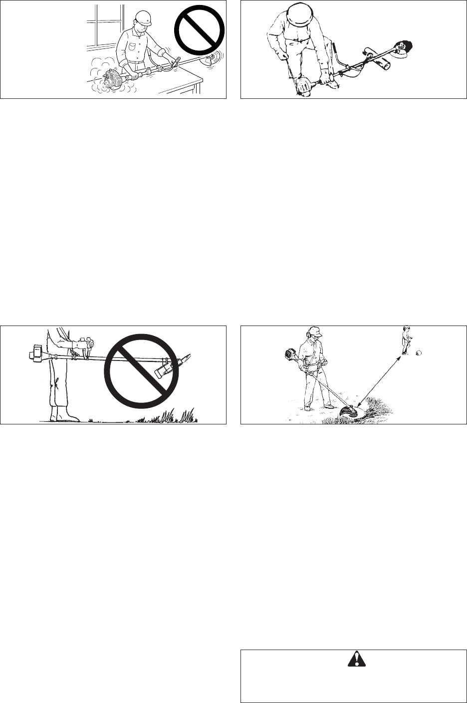
Do not start engine near fuelling spot
FUEL
It is highly flammable.
a) Use an appropriate type of fuel container.
b) Do not smoke or bring flame or sparks near to fuel
supplies.
c) The fuel tank may be under pressure. Always loosen
the fuel cap and wait for pressure to be equalized
before removing the cap.
d) Fill the fuel tank outdoors over bare ground and
install the fuel cap securely. Do not pour fuel indoors.
e) Wipe any spilled fuel off the unit. Then move at least
3 m from the fuelling spot before starting the engine.
f) Never refuel while the engine is still hot, or fuel a
running engine.
g) Do not store the unit with fuel in its tank, because a
fuel leak could start a fire.
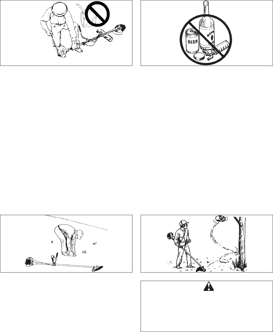
PHYSICAL CONDITION
You should be in good mental and physical health. Do
not operate if you are under the influence of alcohol or
any medication or substance which could affect your
vision, dexterity or judgement.
WARNING DANGER
••
••
•IMPROPER FIT WILL RESULT FLY OFF THE
CUTTING ATTACHMENT.
••
••
•NEVER START THE ENGINE IF THE POWER
TRANSMISSION SHAFT IS NOT IN PLACE TO
PREVENT THE ENGINE FROM OVER SPEEDING
OR THE CLUTCH FROM FLYING APART.
AREA AND EQUIPMENT INSPECTION
Inspect the area before using the unit. Remove objects
the unit could throw. Remember where there are
obstructions to be avoided.
Inspect the unit before using it. Perform only
maintenance or adjustments for which the operator’s
Manual gives instruction. Do not try to repair the unit
without proper instruction. The unit should be serviced
only by trained ECHO dealer servicemen with the proper
tools.
Be sure that:
a) Engine does not leak fuel.
b) Fasteners are tight, and none are missing.
c) Silencer is in good condition.
d) The unit has the proper equipment-shield, handles,
harness, etc.-for the cutting attachment to be used.
e) If used on the unit, the cutting attachment is properly
tightened.
6
SRM-2305
WARNING DANGER
EYE PROTECTION SHOULD BE CONSIDERED
FOR EVERYONE IN THE ZONE OF RISK. RISK OF
EYE INJURY DIMINISHES WITH DISTANCE.
Do not raise the cutting attachment above knee height.
If raised higher, the cutting attachment will be more
directly in line with your face. Thrown objects may hit
your face and eyes.
Wear the recommended protective gear.
Never operate the unit without the proper guards,
shoulder harness and other protective devices.
Never operate the unit without good visibility and light.
15 m
Do not allow anyone to enter the operating DANGER
ZONE with you. The danger zone is an area of 15 m in
radius.
Insist that persons in the RISK ZONE beyond the
danger zone wear eye protection to protect them from
thrown objects. If the unit must be used where there are
unprotected people, operate at a low throttle speed to
reduce the risk.
Ensure that there are no children, bystanders, and pets
in the work area. Keep all children, bystanders and
fellow workers outside 15 m radius for brushcutters/
grasstrimmers.
Stop the engine before leaving the machine, children
are not allowed to use the machine, stop the machine
between different working places.
If you are approached, stop the engine and cutting
attachment immediately. Keep your hands and body
away from silencer to prevent heat injury while the
engine is hot.
Lay the unit down on a clear area and set the controls
for starting. Be sure the cutting attachment cannot
contact the ground or any obstruction.
Hold the unit firmly down so you will not lose control
during starting. Do not start the unit in the air, or from
the harness. The unit could swing into your leg or an
obstruction if you lose control.
GENERAL OPERATION
Engine fumes contain deadly poisonous carbon
monoxide.
Do not operate with a worn or damaged cutting attach-
ment.
Do not run engine at full throttle without a load.
Do not hit rocks, stones, tree stumps, and other foreign
objects with the cutting attachment.
If cutting attachment strikes an obstruction, stop engine
immediately and inspect cutting attachment for damage.
Start on ground with cutting
attachment in the clear
Do not run the
engine indoors, or
where there is poor
ventilation.
7SRM-2305
When the unit is turned off, make sure the cutting
attachment stops before the unit is set down.
A cutting attachment can injure while it continues to spin
after the engine is shut off or throttle control is released.
If the cutting attachment rotates after throttle is returned
to idle, carburettor adjustment is required. Follow
instruction on this manual to make the adjustment
yourself, or have the carburettor adjusted by your ECHO
dealer.
All maintenance and adjustments given in this manual
should be performed by you or your ECHO servicing
dealer on a timely basis.
All required service or repair must be done only by
ECHO servicing dealer. Never attempt to use an
incomplete or one fitted with unauthorized modification.
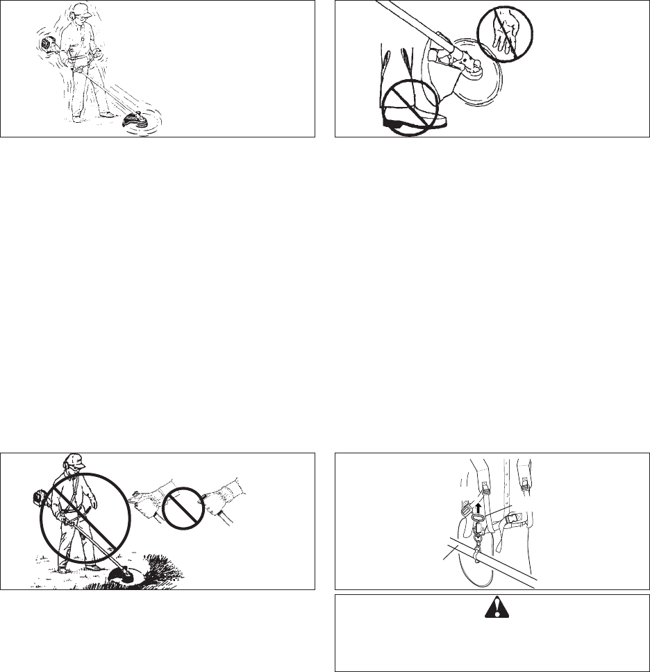
Keep feet and hands away
until rotation stops.
Sudden vibration?
Shut down immediately!
Shut down immediately if the unit starts to shake or
vibrate.
A sudden vibration is a sign there may be dangerous
trouble, such as a broken flywheel, clutch or cutting
attachment, or loose parts.
Do not use the unit until the problem has been properly
diagnosed and corrected.
Do not operate one-handed
Always use both hands on the handles. Do not operate
one-handed.
Always hold the unit with the fingers and thumbs
encircling the handles.
WARNING DANGER
IN CASE OF AN EMERGENCY, USE QUICK-
RELEASE PIN ON HARNESS TO FREE YOURSELF
FROM UNIT.
Shaft tube
Quick-release pin
Pull out
8
SRM-2305
VIBRATION AND COLD
It is believed that a condition called Raynaud’s Phenom-
enon which affects the fingers of certain individuals may
be brought about by exposure to vibration and cold.
Exposure to vibration and cold may cause tingling and
burning, followed by loss of colour and numbness in the
fingers.
The following precautions are strongly recommended
because the minimum exposure which might trigger the
ailment is unknown.
•Keep your body warm, especially the head and neck,
feet and ankles, and hands and wrists.
•Maintain good blood circulation by performing
vigorous arm exercises during frequent work breaks,
and also by not smoking.
•Limit the number of hours of operation.
Try to fill each day with jobs where operating the
trimmer or other hand-held power equipment is not
required.
•If you experience discomfort redness and swelling of
the fingers, followed by whitening and loss of feeling,
consult your physician before exposing yourself
further to cold and vibration.
Painful or numb fingers?
See your doctor immediatelty!
REPETITIVE STRESS INJURIES
It is believed that over-using the muscles and tendons of
the fingers, hands, arms and shoulders may cause
soreness, swelling, numbness, weakness and extreme
pain to the areas just mentioned. Certain repetitive hand
activities may put you at a high risk for developing a
repetitive stress injury (RSI).
To reduce the risk of RSI, do the following:
•Avoid using your wrist in a bent, extended or twisted
position.
•Take periodic breaks to minimize repetition and rest
your hands. Reduce the speed and force in which
you do the repetitive movement.
•Do exercises to strengthen hand and arm muscles.
•See a doctor if you feel tingling, numbness or pain in
your fingers, hands, wrists or arms. The sooner RSI
is diagnosed, the more likely permanent nerve and
muscle damage can be prevented.
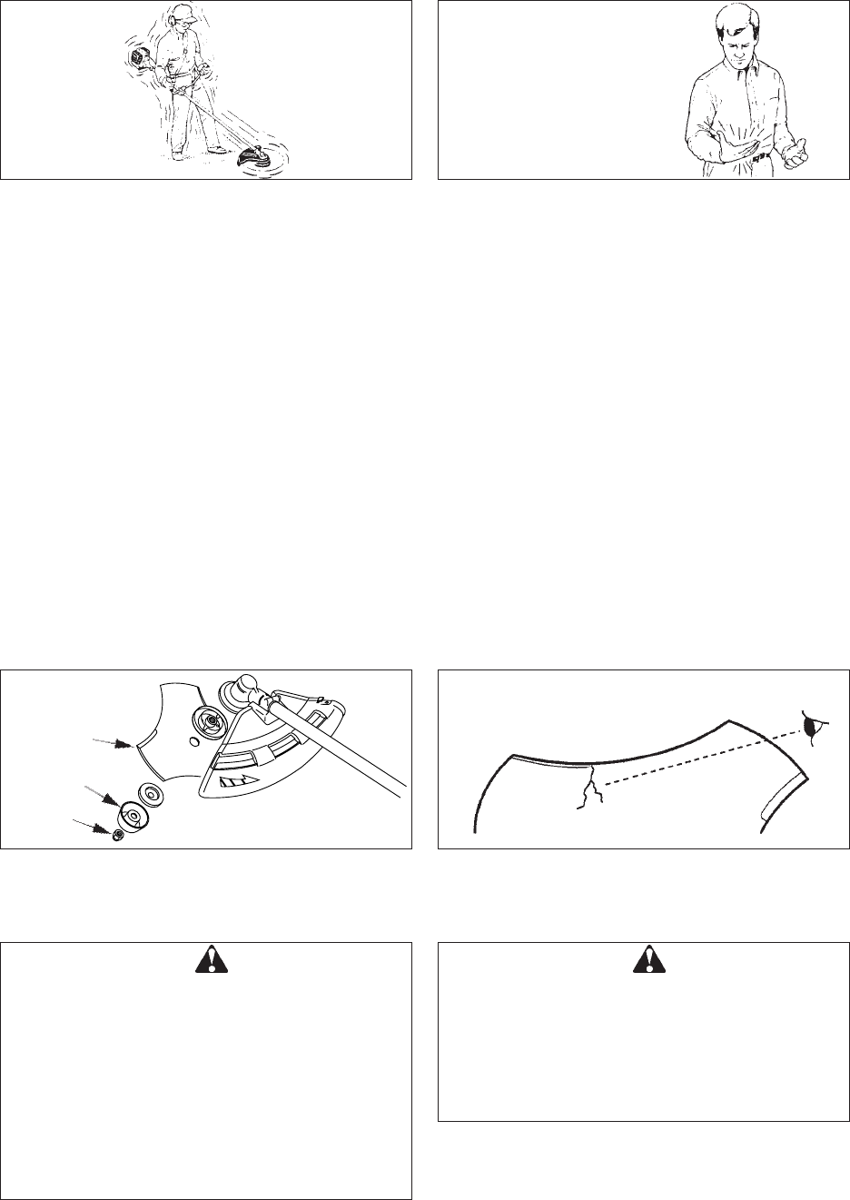
Blade
RULES FOR SAFE OPERATION
(WITH METAL BLADE)
WARNING DANGER
•SERIOUS INJURY MAY RESULT FROM THE
IMPROPER USE OF BLADES.
READ AND COMPLY WITH ALL SAFETY
INSTRUCTIONS LISTED IN THIS MANUAL.
•THE 3 CUTTER BLADE IS DESIGNED
ESPECIALLY TO CUT WEEDS AND GRASS. TO
AVOID INJURY DUE TO KICKBACK OR
BLADE FRACTURE, DO NOT USE THE 3
CUTTER BLADE TO CUT BRUSH OR TREES.
•USE ONLY CUTTING ATTACHMENTS
RECOMMENDED BY KIORITZ CORPORATION.
Cup
USE CORRECT BLADE
WARNING DANGER
PIECES FROM A CRACKED METAL BLADE CAN
FLY OFF DURING OPERATION. INSPECT METAL
BLADES FOR CRACKS BEFORE EACH USE.
DISCARD CRACKED BLADES NO MATTER HOW
SMALL THE CRACK. CRACKED BLADES CAN BE
THE RESULT OF MISUSE OR IMPROPER
SHARPENING.
Inspect blades before use
Nut
9SRM-2305
Wires can catch
and flap around
•Always use the blade suited for the job.
•Do not hit rocks, stones, tree stumps, and other
foreign objects with the blade.
•Do not cut into the ground with the blade.
•If blade strikes an obstruction, stop engine immedi-
ately and inspect blade for damage.
•Do not operate with a dull, bent, fractured or
discoloured blade and worn or damaged nut.
•Do not run engine at full throttle without a load.
•Remove all foreign objects from work area.
•Do not operate brushcutter without shoulder harness
and shield.
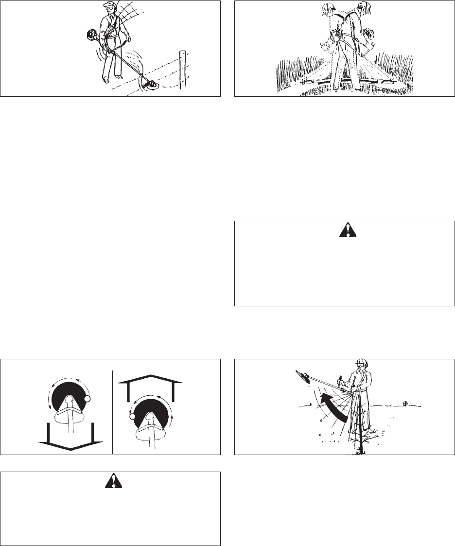
REACTION FORCES
Anticlockwise rotation
Push
PUSH. The operator may feel the unit push toward him
when he tries to cut the object on right. If he cannot hold
the blade in the cut, a kickback may occur when the
blade is pushed out to where the teeth at the outside
furthest point from the operator are cutting. The blade
will “kickback” sideways.
PULL. The opposite of push. When object on left, the
operator may feel the unit pull away. Although this pull
type of cutting may cause sawdust to be thrown back at
the operator, it is recommended for sawing off heavy
brush because the cutting is smoother and more stable
than when the unit pushes.
Pull
Kickback
WARNING DANGER
BE SURE YOU UNDERSTAND THE REACTION
FORCES OF PUSH AND PULL, AND KICKBACK
DESCRIBED IN THIS MANUAL, AND HOW THESE
FORCES MAY AFFECT YOUR BALANCE IN THE
OPERATION OF A UNIT.
KICKBACK. This may occur when the moving blade at
the front of the blade circle contacts strong brush or
trees. The force that occurs pushes the entire unit and
blade violently away in an arc. Kickback is a danger to a
bystander and also a jolting force to the operator.
WARNING DANGER
ALWAYS STOP THE ENGINE WHEN A CUTTING
ATTACHMENT JAM OCCURS. DO NOT ATTEMPT
TO REMOVE AN OBJECT CAUSING A JAM IF THE
ENGINE IS RUNNING. SEVERE INJURY CAN
OCCUR IF A JAM IS REMOVED AND THE
CUTTING ATTACHMENT SUDDENLY STARTS.
SCYTHING WEEDS. This is cutting by swinging the
cutting attachment in a level arc. It can quickly clear
areas of field grass and weeds. Scything should not be
used to cut large, tough weeds or woody growths.
If a sapling or shrub binds the cutting attachment, do not
use the cutting attachment as a lever to free the bind,
because this will cause cutting attachment failure.
Instead, shut off the engine and push the sapling or
shrub to free the blades.
Do not use a cracked or damaged blade.
10
SRM-2305
SCALPING AND EDGING: Both of these are done with
the line head or line disc tilted at a steep angle. Scalping
is removing top growth, leaving the earth bare. Edging is
trimming the grass back where it has spread over a
pavement or driveway. During both edging and scalping,
hold the unit at a steep angle in a position where the
debris, and any dislodged dirt and stone, will not come
back towards you even if it ricochets off the hard
surface.
Although the pictures show how to edge and scalp,
every operator must find for himself the angles which
suit his body size and cutting situation.
Debris
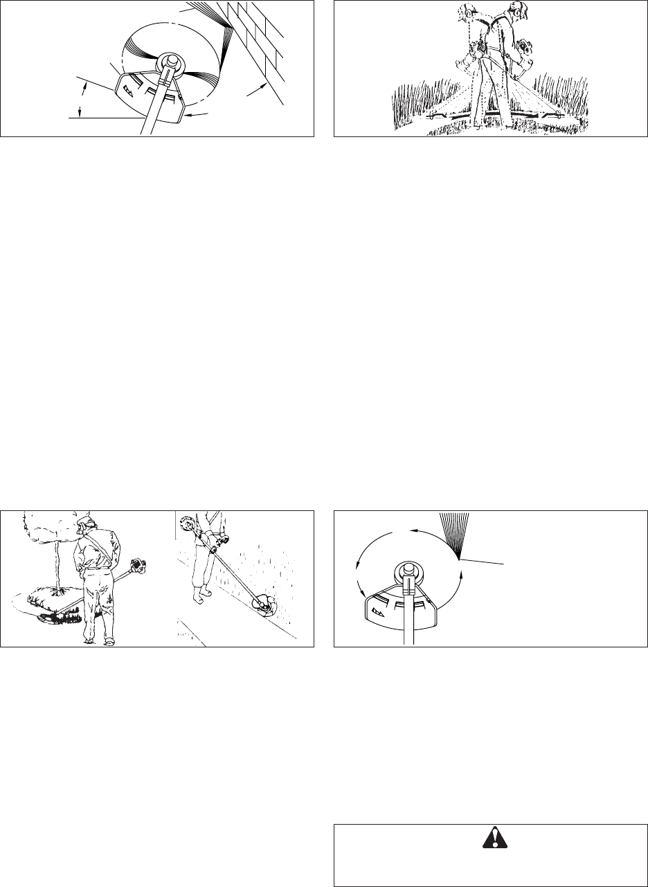
For nearly all cutting, it is good to tilt the nylon cutter so
that contact is made on the part of line circle where the
line is moving away from you and the shield (See
appropriate picture). This results in the debris being
thrown away from you.
Tilting the head to the wrong side will shoot the debris
toward you. If the nylon line cutter is held flat to the
ground so that cutting occurs on the whole line circle,
debris will be thrown at you, drag will slow the engine,
and you will use up a lot of line.
Nylon line head or disc
rotates anticlockwise.
The knife will be on the
left side of the shield.
Cut on this side
WARNING DANGER
USE ONLY FLEXIBLE, NON-METALLIC LINE
RECOMMENDED BY KIORITZ CORPORATION.
EdgingScalping
RULES FOR SAFE OPERATION
(WITH NYLON LINE CUTTING HEAD)
Angle to wall
The basic cutting actions pictured are:
Trimming, scything, scalping and lawn edging.
These actions are as follows:
TRIMMING: This is feeding the trimmer carefully into the
material you wish to cut. Tilt the head slightly to direct
the debris away from you. If cutting up to a barrier such
as a fence, wall or tree, approach from an angle where
any debris ricocheting off the barrier will fly away from
you. Move the line head or line disc slowly until the
grass is cut right up to the barrier, but do not jam
(overfeed) the line into the barrier. If trimming up to wire
mesh or chain link fencing, be careful to feed only up to
the wire. If you go too far, the line will snap off around
the wire.
Trimming can be done to cut through weed stems one at
a time. Place the nylon line cutter near the bottom of the
weed never high up, which could cause the weed to
chatter and catch the line. Rather than cut the weed
right through, just use the very end of the line to wear
through the stem slowly.
Debris
Knife side raised
Angle to ground
SCYTHING: This is the cutting or mowing of large
grassy areas by sweeping or swinging the trimmer in a
level arc. Use a smooth, easy motion. Do not try to hack
or chop down the grass. Tilt the line head or line disc to
direct the debris away from you on the scything stroke.
Then return without cutting grass for another stroke. If
you are well protected and do not care whether some
debris is thrown in your direction, you may scythe in
both directions.
11 SRM-2305
WARNING DANGER
USE EXTREME CAUTION WHEN OPERATING
OVER BARE SPOTS AND GRAVEL, BECAUSE
THE LINE CAN THROW SMALL ROCK PARTICLES
AT HIGH SPEEDS. THE SHIELD ON THE UNIT
CANNOT STOP OBJECTS WHICH BOUNCE OR
RICOCHET OFF HARD SURFACES.
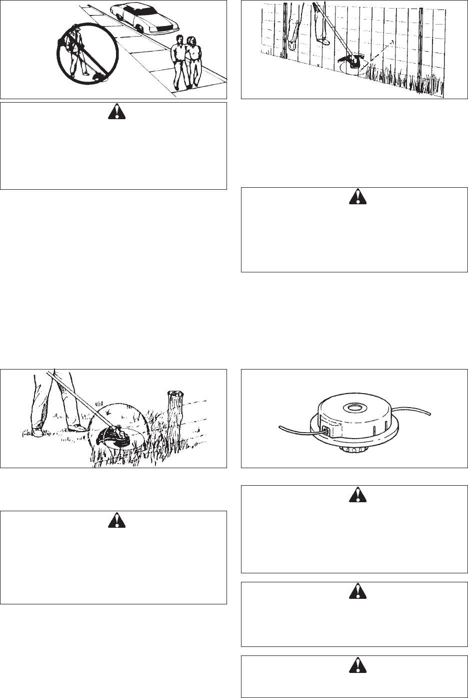
Do not trim near cars or pedestrians.
Always wear proper eye protection against thrown
objects. Objects can bounce up at you from the ground
under the shield, or ricochet off any nearby hard
surface.
Do not trim at high speed near roadways when there is
traffic, or in places where there are pedestrians. If you
must trim where people are in the zone of risk use a
much lower or reduced speed, by using a partial trigger
setting. Do not use full throttle.
Do not push the line into tough weeds, trees, or wire
fences. Pushing the line into chicken wire, chain link
fencing or thick brush can result in snapped-off line
ends being hurled back at the operator. The proper way
is to cut right up to a barrier, such as any of those
mentioned, but never run the line into or through the
obstruction. Do not cut closely to obstruction or barrier.
Line pushed into wire
fencing will snap off.
WARNING DANGER
ALWAYS STOP THE ENGINE WHEN A CUTTING
ATTACHMENT JAM OCCURS. DO NOT ATTEMPT
TO REMOVE AN OBJECT CAUSING A JAM IF THE
ENGINE IS RUNNING. INJURY CAN OCCUR IF A
JAM IS REMOVED AND THE CUTTING
ATTACHMENT SUDDENLY STARTS.
WARNING DANGER
•SERIOUS INJURY MAY RESULT FROM THE
IMPROPER USE OF CUTTING ATTACHMENT.
READ AND COMPLY WITH ALL SAFETY
INSTRUCTIONS LISTED IN THIS MANUAL.
•USE ONLY CUTTING ATTACHMENTS
RECOMMENDED BY KIORITZ CORPORATION.
WARNING DANGER
USE ONLY NYLON LINE. DO NOT USE ANY TYPE
OF METAL BLADE.
WARNING DANGER
EXCESSIVE NYLON LINE BEYOND CUT OFF
KNIFE COULD FLY OFF WHEN THE NYLON LINE
CUTTER STARTS ROTATING AFTER
ADJUSTMENT OF NYLON LINE LENGTH.
F-4/10
Avoid wire
Avoid nylon line contact with broken wire fencing. Pieces
of wire broken off by the trimmer can be hurled at high
speeds.
WARNING DANGER
DO NOT TRIM IN ANY AREA WHERE THERE ARE
BROKEN STRANDS OF FENCING WIRE. REMOVE
THE BROKEN PIECES OF WIRE, OR GIVE THE
AREA WIDE BERTH. WEAR PROPER SAFETY
PROTECTION. DO NOT CUT WHERE YOU
CANNOT SEE WHAT THE CUTTING DEVICE IS
CUTTING.
USE CORRECT CUTTING ATTACHMENT
12
SRM-2305
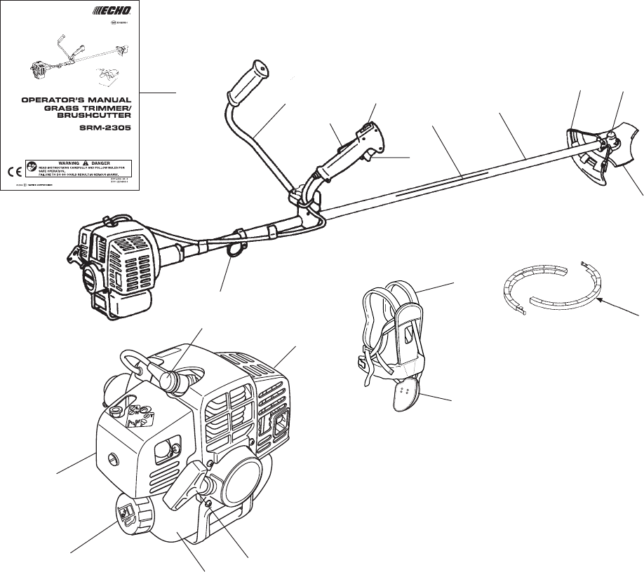
DESCRIPTION
1OPERATOR’S MANUAL Included with unit. Read
before operation and keep for future reference to
learn proper, safe operating techniques.
2ANGLE TRANSMISSION Having two gears to
change the angle of rotating axis.
33 CUTTER BLADE For cutting grass, garden debris
and weeds.
4SHIELD Device to protect the operator from accidental
contact with the cutting head and thrown objects.
5SHAFT TUBE Part of the unit that provides a casing
for power transmission shaft.
6U-HANDLE Having the configuration of a bicycle
handle bar.
7SUSPENSION POINT Device on which the harness
can be hooked.
8IGNITION SWITCH “Slide Switch” mounted on top
of the Throttle Trigger Housing, move switch upward
to RUN, downward to STOP position.
9THROTTLE TRIGGER Activated by the operator’s
finger for controlling the engine speed.
10 THROTTLE TRIGGER LOCKOUT Locks throttle
trigger in the idling position until you have a proper
grip with your right hand around the handle.
11 AIR CLEANER COVER Covers air filter.
12 FUEL TANK CAP For closing the fuel tank.
13 FUEL TANK Contains fuel and fuel filter.
14 STARTER HANDLE Pull handle to start the engine.
15 SILENCER COVER Cover the silencer not to make
operator touch to hot surface of silencer.
16 SPARK PLUG
17 SHOULDER HARNESS An adjustable strap to
suspend unit.
18 HIP PAD To protect hip/leg and clothing.
19 BLADE COVER When transporting the unit, use the
appropriate metal blade cover.
20 SAFETY DECAL Part Number 890617-43130
1
19
16
15
14
12
11
13
6
10
8
9
5
4
3
2
7
20
18
17
13 SRM-2305
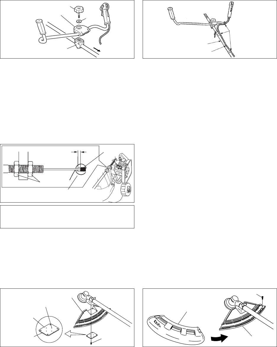
ASSEMBLING
Handle assembling bolt (8 mm)
Handle assembling
bracket (lower) To engine
Washer
Install handle assembling bracket (upper) in handle
assembling bracket (lower) and fix handle by tightening
handle assembling bolt (8 mm) lightly.
Adjust inclination of handle to adequate position (easy to
operate) and tighten firmly handle assembling bolt (8 mm).
To eliminate loosening of throttle wire fix it to shaft tube
(2 places) and to right hand U-handle (1 place) with wire
fixing clips.
Handle assembling
bracket (upper)
Wire fixing clip
Shaft tube
Throttle wire
Nuts
CAUTION
After assembly, adjust the play of wire end on
carburettor side to 1 mm - 2 mm.
1 - 2 mm
Carburettor
Wire end
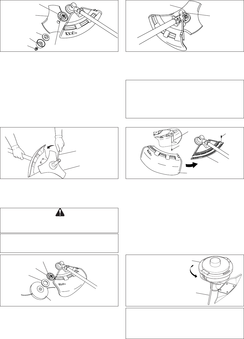
INSTALLATION OF BRACKET
Fit bracket to mounting portion of angle transmission and
fix the bracket by holding fitting plate pressed from beneath
and tightening 4 bolts (M5×25) lightly.
Get notches and convexes of fitting plate to face
corresponding convexes and concaves of bracket, and fix
bracket tightening 4 bolts (M5×25) securely.
Bracket
Bolt M5×25
Convex of fitting plate
Fitting plate
Notch of
fitting plate
There are two types of shields: namely one used exclusively
for Nylon line and another one used exclusively for steel
blade. When Nylon line is used, use the shield for Nylon
line. When steel blade is used, use the shield for steel
blade.
METHOD TO CHANGE SHIELD
(FOR STEEL BLADE)
Remove screw (M5×18) on the right side of the shield and
slide the shield to the left and remove it. Put shield of
another type into groove and slide it to the right until it stops
and be sure to fasten with the removed screw (M5×18).
When using Nylon line, use the shield for Nylon line
(see page 15). Fit cut off knife to the shield for Nylon line
using screw (5×12).
Bracket
Shield
Screw M5×18
14
SRM-2305
WARNING DANGER
IF WORN NUT AND CUP FOR BLADE ARE USED,
THERE IS A DANGER OF BLADE GETTING
LOOSE. REPLACE THEM WITH NEW ONES.
METHOD TO CHANGE SHIELD
(FOR NYLON LINE)
Remove screw (M5×18) on the right side of the shield
and slide the shield to the left and remove it. Put shield
of another type into groove and slide it to the right until it
stops and be sure to fasten with the removed screw
(M5×18).
Bracket
Shield
Screw
M5×18
Cut off knife
Screw
5×12
INSTALLING NYLON LINE CUTTING
ATTACHMENT
Insert locking tool into a hole located on the right side of
angle transmission while forcing retainer spring to the
left side. Insert locking tool further into blade retainer
fixing slot to fix output shaft.
Blade retainer fixing slot
Blade retainer
Washer
Nylon line cutting attachment
CAUTION
Fasten output shaft using locking tool securely in
order to avoid the possibility of output shaft
rotating when mounting nylon line cutting
attachment.
Thread cutting attachment onto shaft (anticlockwise)
until it is tight.
Remove locking tool.
INSTALLING BLADE
Inspect blades before installation. Check for sharpness.
Dull blades increase the risk of blade kickback reactions.
Small cracks can develop into fractures resulting in a piece
of blade flying off during operation.
Discard cracked blades no matter how small the crack.
Blade retainer, blade, lower blade retainer, cup and nut
finger tight.
Blade retainer fixing slot
Blade retainer
Blade
Lower blade retainer
Cup
Nut
CAUTION
Fasten output shaft using locking tool securely in
order to avoid the possibility of output shaft
rotating when mounting cutting blade which will
prevent the cutting blade fastening nut from
being tightened sufficiently.
Insert locking tool into a hole located on the right side of
angle transmission while forcing retainer spring to the left
side. Insert locking tool further into blade retainer fixing slot
to fix output shaft.
Blade
Locking tool
Locking tool
Nylon line cutting attachment
Socket wrench
CAUTION
Wear gloves to reduce the risk of injury caused
by unintentional contact with the blade.
Tighten the nut (turn anticlockwise) using a socket wrench.
Never fasten while applying your weight. Otherwise the
thread of nut could be broken.
Replace nut and cup with new ones no matter how small
the wear is.
Blade
15 SRM-2305
NYLON LINE CUTTING ATTACHMENT
Type: F-4/10
Thread: Left-hand thread M10 × 1.25 pitch
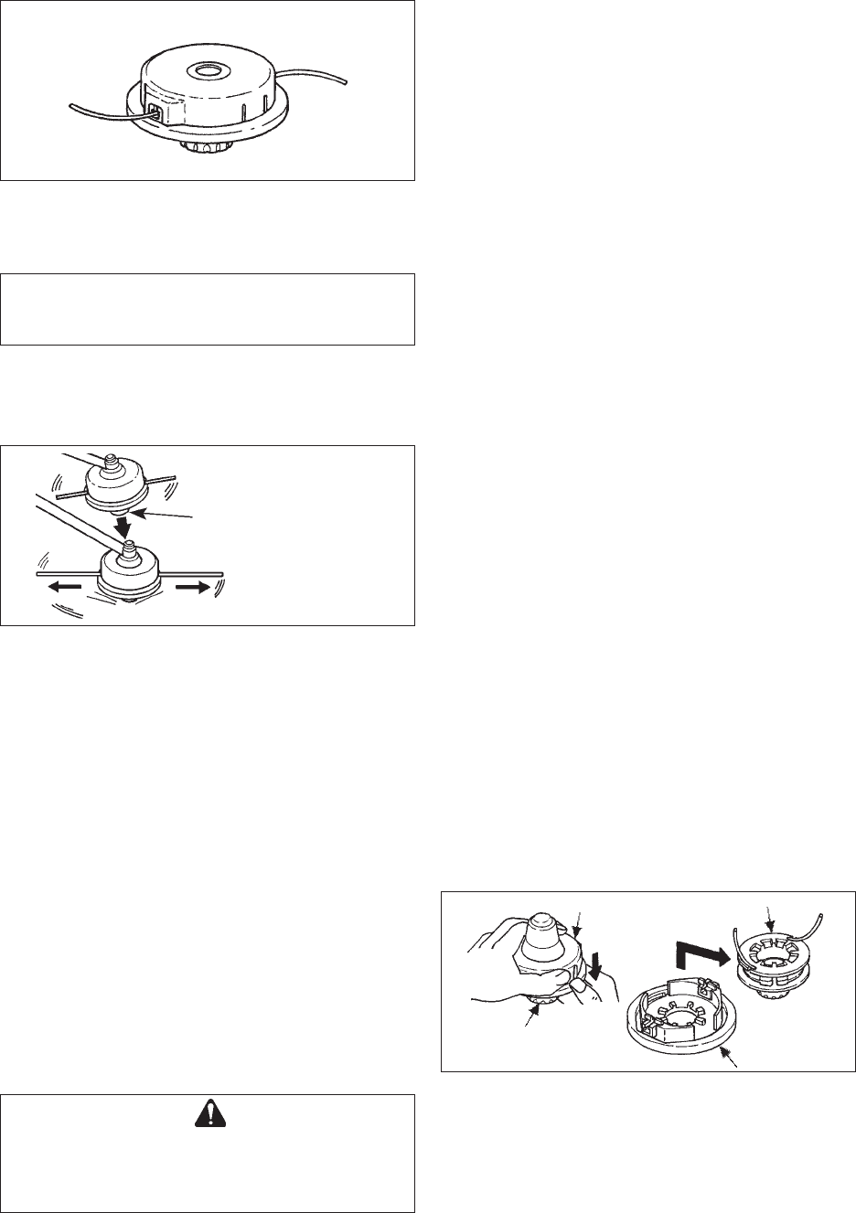
ADJUSTING NYLON LINE
• Make sure there is no bystander within 15 m radius
and pay enough attention to objects in the
surroundings before starting operation.
• Do not rotate the cutting head at more than 10,000
r/mim.
• Do not hit the cutting head against hard foreign
matters such as rocks, concrete, tree stub and bottle
etc.
Tap knob
Hit knob against the
ground surface lightly
Nylon line comes out
• When releasing Nylon line from spool hit tap knob of
spool against the ground surface lightly at rotation
speed lower than 4,500 r/min.
• Cut off knife on the guard adjusts cutting swath to 40
cm automatically by cutting nylon lines evenly when
attachment starts rotating.
• When operating with less than maximum cutting
swath (40 cm), cut two nylon lines in equal lengths.
CAUTION
Use only flexible, non-metallic line recommended
by KIORITZ CORPORATION.
Tap knob of spool
Housing Spool
Cover
REPLACING NYLON LINE
F-4/10
(1)
(2)
(3)
(1) Press “retaining pawls” (at two places) inward and
remove cover.
It is easier to remove one after another.
(2) Remove spool.
(3) When Nylon line on the spool is almost exhausted,
remove remaining line from spool and wind “new line”
according to the procedures (4) and beyond.
When the line on the spool is “melted and stuck”
remove the entire line while peeling off the “melted and
stuck” portion and wind the “removed line” anew
according to procedures (4) and beyond.
WARNING DANGER
SHUT DOWN TRIMMER ENGINE WITHOUT FAIL
AND MAKE SURE CUTTING HEAD HAS STOPPED
ROTATING BEFORE STARTING REPLACEMENT
PROCEDURE.
16
SRM-2305
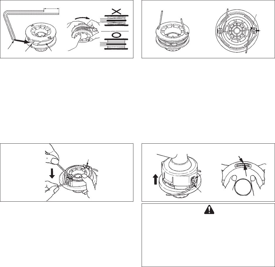
(8) Pull out the line from cover.
(A) Remove the line from “respective notch of spool”,
and (B) pass it through “groove of respective eyelet”.
(9) Fit cover and housing together.
(C) Align “eyelets” of cover with “recesses” of housing,
and (D) press pawls of housing into respective window
of cover until the pawls are firmly fitted into the
windows.
(6) (7)
(6) When the line is wound to the end hook both line ends
into respective notch of spool for retaining tentatively
the line while leaving line ends approximately 10 cm
beyond notch.
(7) Align notches of spool for the line with grooves of
eyelets and fit spool into cover.
(8)
WARNING DANGER
MAKE SURE EACH OUTER PERIPHERY OF
PAWLS OF HOUSING SPREADS ALMOST FULLY
UP TO THE OUTER PERIPHERY OF RESPECTIVE
WINDOW OF COVER.
IF THEY ARE LOOSELY FITTED AND THE
CUTTING HEAD IS TURNED, COVER OR INSIDE
COMPONENTS CAN FLY OFF WHICH IS
DANGEROUS.
(A)
(B) (C)
(D)
(9)
1. Intermediate separator
2. Bent portion
3. Notch Nylon line
4. Winding direction for the line
5. If wound unfirmly, the line loosens.
6. Wind firmly into respective groove.
(4) Bend the line at the point 12 cm away from the middle
of whole length and hook the bent portion into the
“notch” of the intermediate separator.
(5) Wind the line firmly into groove of the spool following
“winding direction for the line LH”.
12 cm
1
23
45
(4) (5)
6
17 SRM-2305
FUEL
• Fuel is a mixture of regular grade petrol and an air-
cooled 2-stroke engine oil of reputable brand name.
Minimum 89 Octane unleaded petrol is
recommended. Do not use fuel containing methyl
alcohol or more than 10 % of ethyl alcohol.
• Recommended mixture ratio; 50 : 1 (2 %) for ISO-L-
EGD Standard (ISO/CD 13738), JASO FC grade
and ECHO Premium 50 : 1.
- Do not mix directly in engine fuel tank.
- Avoid spilling petrol or oil. Spilled fuel should
always be wiped up.
- Handle petrol with care, it is highly inflammable.
- Always store fuel in approved container.
FUEL
NOTE
Stored fuel ages. Do not mix more fuel than you
expect to use in thirty (30) days. Do not mix directly in
fuel tank.
STARTING COLD ENGINE
WARNING DANGER
••
••
•WHEN ENGINE STARTS, THE CUTTING
ATTACHMENT MAY ROTATE, EVEN WITH
THROTTLE TRIGGER IN LOW-SPEED POSI-
TION.
••
••
•WHEN ENGINE IS STARTED, CONFIRM IF
THERE IS NOT ANY ABNORMAL VIBRATION
OR SOUND. IF THERE IS ABNORMAL
VIBRATION OR SOUND, ASK YOUR DEALER
TO REPAIR.
WARNING DANGER
WHEN STARTING ENGINE USING THROTTLE
LATCH, CUTTING ATTACHMENT ROTATES.
AFTER ENGINE STARTS, PULL THROTTLE
TRIGGER SLIGHTLY TO RELEASE THROTTLE
LATCH IMMEDIATELY. NEVER USE THROTTLE
LATCH FOR OPERATION.
OPERATION
Ignition switch
Throttle latch Throttle trigger
lockout
Throttle trigger
START
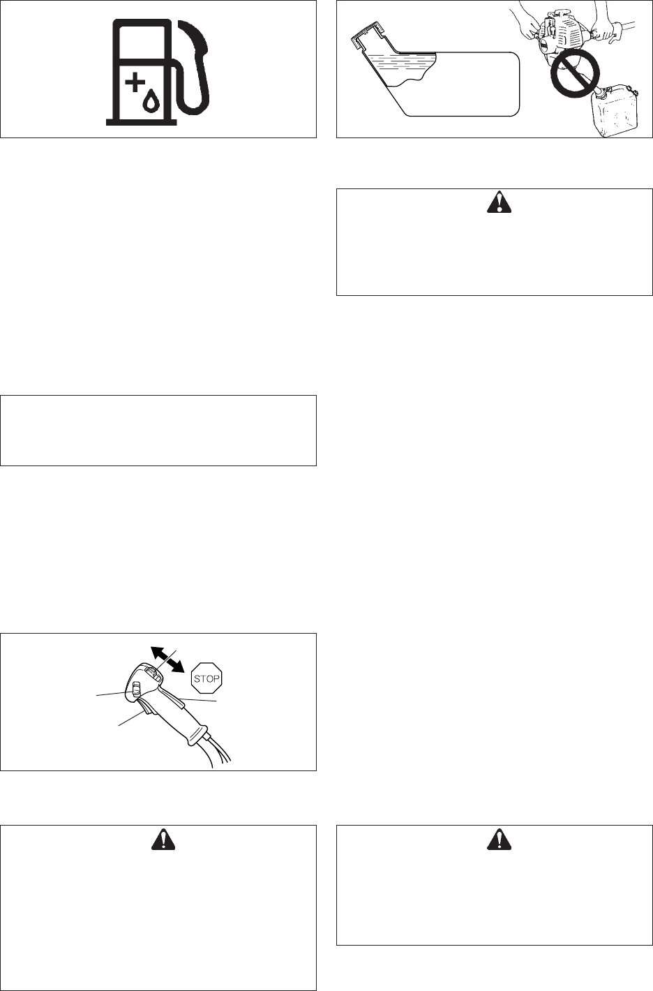
HANDLING FUEL
Shoulder level
Fuel tank
WARNING DANGER
AFTER REFUELLING, TIGHTEN FUEL CAP
FIRMLY AND CHECK FOR LEAKAGE. IN CASE OF
FUEL LEAKAGE, REPAIR BEFORE STARTING
OPERATION SINCE THERE IS A DANGER OF
FIRE.
• Never smoke or allow flame or sparks near fuel.
• Always fill the fuel tank outdoors. Never pour fuel
indoors.
• Always remove the fuel cap slowly to relieve any
pressure buildup in the tank.
• Never refuel the engine when it is hot or running.
• Always use an approved, safe fuel container.
• It is not permitted to fill fuel above the shoulder level of
fuel tank.
• After fuelling, always wipe away spilled fuel.
• Always move at least 3 m away from the fuelling spot
before starting the engine.
• Never store the unit with fuel in the tank a fuel leak
could start a fire.

18
SRM-2305
STOPPING ENGINE
• Release throttle trigger and allow engine to idle.
• Place ignition switch in “STOP” position.
WARNING DANGER
IF ENGINE DOES NOT STOP, CLOSE CHOKE TO
STALL ENGINE. HAVE YOUR ECHO DEALER
INSPECT AND REPAIR IGNITION SWITCH
BEFORE USING THE UNIT.
Always disconnect the spark plug wire from the spark plug
to ensure the engine cannot be started before you work on
the unit or leave it unattended.
NOTE
If engine does not start after 4 pulls, use Cold
Starting Procedure.
STARTING WARM ENGINE
• Place ignition switch in “START” position.
• Move choke knob to OPEN position.
• If tank is not empty, pull starter handle.
• If fuel tank is empty, after refilling, push the purge
bulb (until fuel is visible in clear fuel return line). Pull
starter handle.
Spark plug wire
Spark plug
USING SHOULDER HARNESS
Place shoulder harness over both shoulders and adjust
straps so the connecting point latch as shown.
Buckle waist belt. Belt should be snug.
Attach grasstrimmer/brushcutter to harness.
Check for correct adjustment by moving cutting attach-
ment along ground.
Re-adjust position of suspension point if necessary.
NOTE
• Check unit for loose nuts, bolts and screws before
starting.
• Always clear work area of debris before starting
operation.
• Always hold the unit firmly on the ground.
• When pulling starter handle, use short pulls, 1/2 to
2/3 of rope length.
• Do not allow the starter handle to snap back against
the housing.
Ignition switch
Throttle latch Throttle trigger
lockout
Throttle trigger
START
• Before starting engine make sure cutting attachment
is not in touch with ground or other objects.
• Place ignition switch in “START” position.
• Push purge bulb until fuel is visible in clear fuel return
line.
• Pull choke knob up to CLOSE position.
• Pull starter handle until first firing sound.
• Open choke.
• Restart engine and allow to warm up.
• When engine is hard to start, use throttle latch. (Pull
throttle trigger fully and lower throttle latch while
pressing throttle trigger lockout and release throttle
trigger to activate throttle latch. After engine starts,
pull throttle trigger slightly to release throttle latch
immediately.)
Purge bulb
Choke knob
Fuel return line
Starter handle
19 SRM-2305
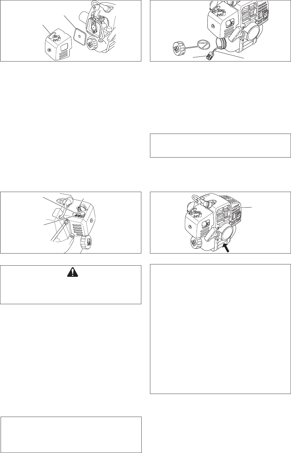
CLEANING AIR FILTER
• Close choke. Loosen screw and remove air cleaner
cover.
• Remove air filter (air filter is located inside air cleaner
cover).
• Brush dirt from filter or clean with compressed air.
• Reinstall filter.
• Reinstall cover and tighten screw.
Air filter
Air cleaner cover
• If you have any questions or problems, please contact
your ECHO dealer.
MAINTENANCE AND CARE
NOTE
If filter is excessive dirty or no longer fits properly,
replace it.
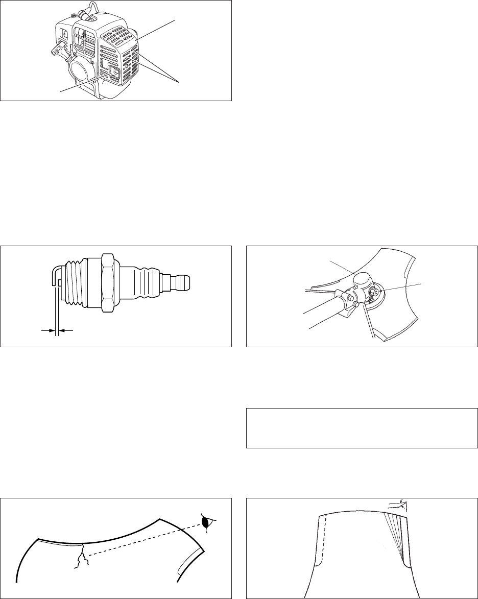
REPLACING FUEL FILTER
• Use a piece of steel wire or the like to pick up fuel filter
through fuel tank opening.
• Pull old filter from fuel line.
• Install new fuel filter.
Fuel filter
H: High speed
mixture adjuster
Fuel line
CARBURETTOR ADJUSTMENT
Every unit is test run at the factory and the carburettor is
fine tuned for maximum performance.
Before adjusting carburettor, clean or replace air filter, start
engine and run several minutes to bring it to operating
temperature.
WARNING DANGER
WHEN CARBURETTOR ADJUSTMENT IS
COMPLETED, CUTTING ATTACHMENT SHOULD
NOT MOVE AT IDLE, OTHERWISE SERIOUS
PERSONAL INJURY MAY RESULT.
To adjust the carburettor proceed as follow:
1. Trun the low speed mixture adjuster (L) and high
speed mixture adjuster (H) anticlockwise to stop.
2. Start engine and turn “idle” speed adjustment screw
(T) clockwise until the cutting attachment begins to
turn, then turn the screw (T) anticlockwise until the
cutting attachment stops turning. Turn screw (T)
anticlockwise an additional 1/4 turn.
3. Accelerate to full throttle for 2 to 3 seconds to clear
excess fuel from engine then return to idle. Accelerate
to full throttle to check for smooth transition from idle to
full throttle.
CAUTION
When starting, idle speed adjuster (T) should be
adjusted not to rotate the cutting attachment.
When there is some trouble with the carburettor,
contact your dealer.
COOLING SYSTEM MAINTENANCE
IMPORTANT
To maintain proper engine operating temperature,
cooling air must pass freely through the cylinder
fin area. This flow of air carries combustion heat
away from the engine.
Overheating and engine seizure can occur when:
• Air intakes are blocked, preventing cooling air
from reaching the cylinder,
or
• Dust and grass build up on the out side of the
cylinder. This build-up insulates the engine and
prevents the heat from leaving.
Removal of cooling passage blockages or
cleaning of cylinder fins is considered “Normal
Maintenance”. Any resultant failure attributed to
lack of maintenance is not warranted.
• Remove dust and dirt from between fins.
• Before each use, remove accumulated debris from
bottom engine intake grille located between the fuel
tank and starter.
Air intake
Cylinder fins
L: Low speed
mixture adjuster
T: Idle speed adjuster
20
SRM-2305
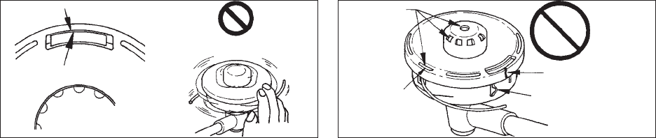
CLEANING SILENCER
•Clean deposits from silencer and tighten two bolts.
ANGLE TRANSMISSION
• Remove plug from angle transmission.
• Add grease, if necessary, using low pressure pump.
• Reinstall plug.
Angle transmission
CHECK SPARK PLUG
• Check plug gap. Correct gap is 0.6 to 0.7 mm.
• Inspect electrode for wear.
• Inspect insulator for oil or other deposits.
• Replace plug if needed and tighten to 15 - 17 N·m
(150 to 170 kgf·cm).
Plug (Bolt)
NOTE
Use good quality lithium multi grease. DO NOT
overfill housing.
30°
CHECKING THE BLADE
•Use only the blade designated for this model by the
manufacturer.
• When a crack is noticed on the blade, do not use it
but replace with a new one.
• Ensure that the blade is correctly fitted in accordance
with the instructions.
• When the cutting blade becomes dull due to wear
reverse it for further use.
• When chip or bend occurs on the blade, vibration will
increase.
Replace with a new one.
• When filing the blade file 3 cutting edges evenly
using a flat file as shown in the illustration.
Otherwise, the balance will be lost and vibration will
increase.
0.6 to 0.7 mm
Silencer
Silencer cover
Two bolts
CHECK FUEL SYSTEM
•Check before every use.
•After refuelling, make sure fuel does not leak or
exude from around fuel pipe, fuel grommet or fuel
tank cap.
•In case of fuel leakage or exudation there is a
danger of fire. Stop using the machine immediately
and request your dealer to inspect or replace.
21 SRM-2305
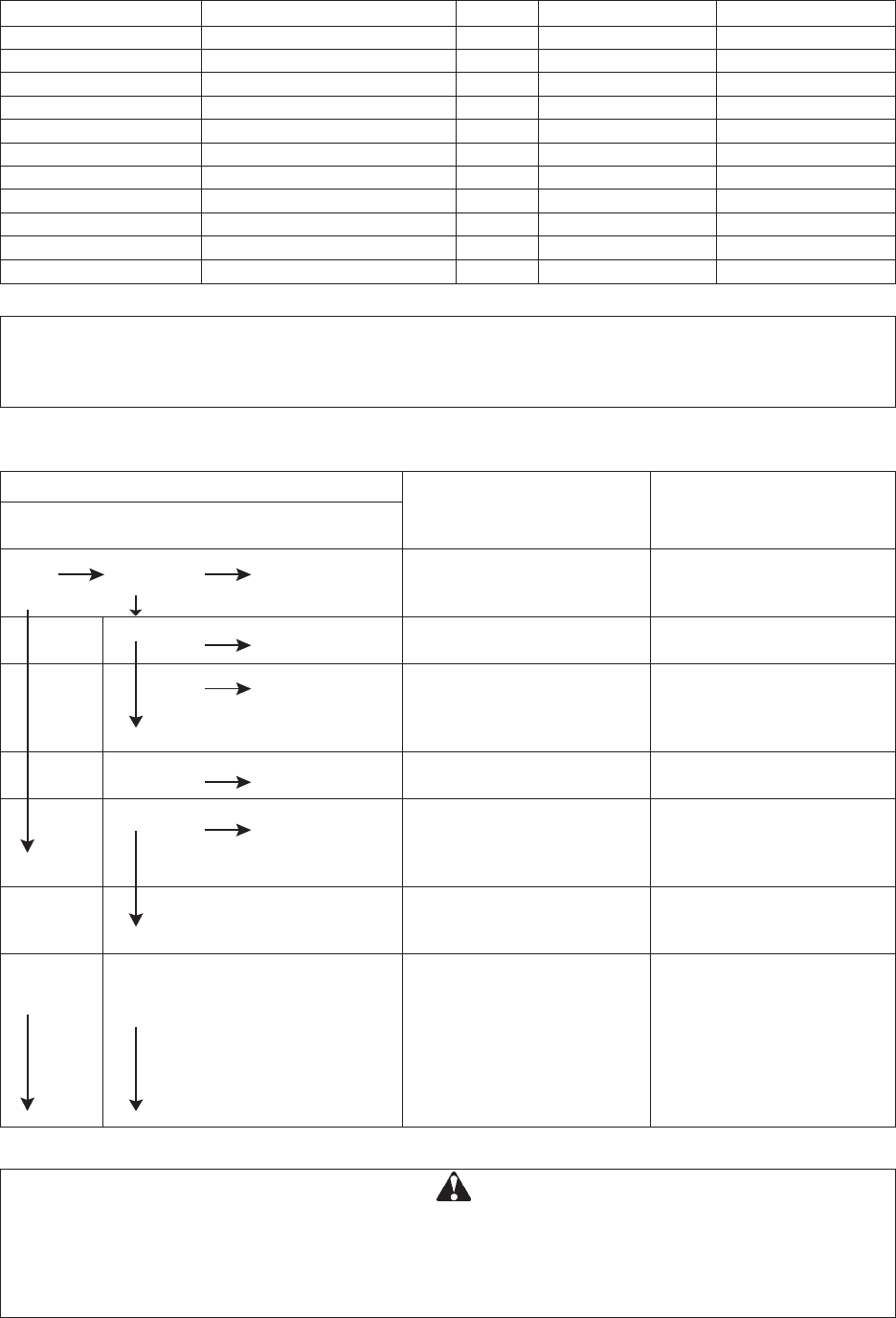
CHECKING THE NYLON LINE CUTTING
ATTACHMENT
(1) Make sure each periphery of the 2 retaining pawls of
housing spreads almost fully up to the outer periphery
of the respective cover window.
(2) Check mount of cutting head on trimmer and tighten if
it is loose.
(3) Check the cutter head for deflection or abnormal noise
rotating it by hand.
Deflection or abnormal noise can cause abnormal
vibration to occur or mount to trimmer to loosen during
rotation which is dangerous.
(4) Inspect cover and tap knob for wear.
When slot appears on bottom of the tap knob or when
slot appears on cover bottom close to outlet for Nylon
line, replace them with new parts without fail.
(5) Check the cutting head for crack or chip.
Replace parts that show any crack or chip with new
ones without fail.
(1) (3) (4)
(5)
22
SRM-2305
Cause
•Fuel filter clogged
•Fuel line clogged
•Carburettor
•Carburettor
•Fuel mixture is too rich
•Ignition switch off
•Electrical problem
•Spark gap incorrect
•Covered with carbon
•Fouled with fuel
•Spark plug defective
•Internal engine problem
•Air filter dirty
•Fuel filter dirty
•Fuel vent plugged
•Spark plug
•Carburettor
•Cooling system plugged
•Exhaust port/silencer
plugged
Trouble
- hard to start
- does not start
Fuel at
carburettor
Fuel at cylinder
Spark at end of
plug wire
Spark at plug
Dies or
accelerates
poorly
TROUBLE SHOOTING
Engine
Engine
cranks
Engine
does not
crank
Engine
runs
No fuel at
carburettor
No fuel at
cylinder
Silencer wet with
fuel
No spark at end
of plug wire
No spark at plug
Remedy
•Clean or replace
•Clean
•Ask your ECHO dealer
•Ask your ECHO dealer
•Open choke
•Clean/replace air filter
•Adjust carburettor
•Ask your ECHO dealer
•Turn switch on
•Ask your ECHO dealer
•Adjust 0.6 to 0.7 mm
•Clean or replace
•Clean or replace
•Replace plug
•Ask your ECHO dealer
•Clean or replace
•Clean or replace
•Clean
•Clean and adjust/replace
•Adjust
•Clean
•Clean
WARNING DANGER
• ALL TRIMMER SERVICE OPERATIONS, OTHER THAN ITEMS LISTED IN THE OPERATOR’S MANUAL,
SHOULD BE PERFORMED BY COMPETENT SERVICE PERSONNEL.
• FUEL VAPORS ARE EXTREMELY FLAMMABLE AND MAY CAUSE FIRE AND/OR EXPLOSION. NEVER
TEST FOR IGNITION SPARK BY GROUNDING SPARK PLUG NEAR CYLINDER PLUG HOLE,
OTHERWISE SERIOUS PERSONAL INJURY MAY RESULT.
SERVICING GUIDE
IMPORTANT
Time intervals are maximum. Actual use and your experience will determine the frequency of required
maintenance.
* Or 50 hours, whichever occurs first.
AREA MAINTENANCE PAGE BEFORE USE MONTHLY
Air Filter Clean/Replace 19 •
Fuel Filter Inspect/Clean/Replace 19 •
Spark Plug Inspect/Clean/Adjust/Replace 20 •
Carburettor Adjust/Replace and adjust 19 •
Cooling System Inspect/Clean 19 •
Silencer Inspect/Tighten/Clean 20 •
Angle Transmission Grease 20 •*
Starter Rope Inspect/Replace - •
Cut off Knife Inspect/Clean - •
Fuel System Inspect 20 •
Screws, Bolts and Nuts Inspect, Tighten/Replace - •

23 SRM-2305
NOTE
•For future reference, you should keep this
operator’s manual.
•If this operator’s manual has become illegible
through impairment or is lost, please purchase a
new one from your ECHO dealer.
•When renting or lending this machine to a person
who will operate it, always include this operator’s
manual, which provides explanation and
instructions.
•When transferring a product, please deliver it
attaching the operator’s manual.
LONG TERM STORAGE (Over 30 Days)
STORAGE
WARNING DANGER
DO NOT STORE IN AN ENCLOSURE WHERE
FUEL FUMES MAY ACCUMULATE OR REACH AN
OPEN FLAME OR SPARK.
Do not store your unit for a prolonged period of time (30
days or longer) without performing protective storage
maintenance which includes the following:
1. Store unit in a dry, dust free place, out of the reach of
children and other unauthorized persons.
2. Place ignition switch in “STOP” position.
3. Remove accumulation of grease, oil, dirt and debris
from exterior of unit.
Ignition switch
4. Perform all periodic lubrication and services that are
required.
5. Tighten all the screws, bolts and nuts.
6. Drain the fuel tank completely and pull the recoil
starter handle several times to remove fuel from the
carburettor.
7. Remove the spark plug and pour 1/2 tablespoon of
fresh, clean, two-stroke engine oil into the cylinder
through the spark plug hole.
A. Place a clean cloth over the spark plug hole.
B. Pull the recoil starter handle 2 or 3 times to
distribute the oil inside the engine.
C. Observe the piston location through the spark plug
hole. Pull the recoil starter handle slowly until the
piston reaches the top of its travel and leave it
there.
8. Install the spark plug (Do not connect ignition cable).

24
SRM-2305
SRM-2305
Mass :
unit without cutting attachment, empty tank kg 5.6
unit with specified cutting attachment, empty tank kg 6.0
unit with specified cutting attachment, full tank kg 6.3
Volume : fuel tank L 0.4
Cutting attachment :
specified blade diameter mm 230
specified blade thickness mm 2.0
number of cutting teeth 3
blade centre hole diameter mm 25.4
blade rotational speed at maximum allowable
engine speed r/min 10,000
Gear ratio : gear ratio and lubrication 1.36 reduction and good quality lithium grease
Rotational direction of output shaft seen from above : Anticlockwise
External dimensions :
length × width × height mm 1,760 × 690 × 455
Engine :
type Air cooled two stroke single cylinder
engine displacement mL(cm³) 21.2
maximum shaft brake power, measured in
accordance with ISO 8893 kW 0.57
engine speed at maximum engine power r/min 7,500
recommended maximum engine speed r/min 10,000
output shaft speed r/min -
recommended engine idling speed r/min 3,000
engine speed at beginning of clutch engagement r/min 3,700
carburettor Diaphragm type
ignition Flywheel magneto - CDI system
spark plug NGK BPMR7A
starter Recoil starter
clutch Automatic centrifugal clutch
Fuel : Regular grade petrol. Minimum 89 Octane
unleaded petrol is recommended. Do not use fuel
containing methyl alcohol or more than 10 % of
ethyl alcohol.
oil Two stroke, air-cooled engine oil. 50 : 1 for ISO-L-
EGD Standard (ISO/CD 13738), JASO FC grade and
ECHO Premium 50 : 1 oil.
ratio 50 : 1 (2 %)
fuel consumption at maximum engine power L/h 0.56
specific fuel consumption at maximum engine
power g/(kW·h) 737
Sound pressure level : (EN 27917) LpAav = dB(A) 92
Sound power level : (2000/14/EC) LWA = dB(A) 108
Vibration levels : (ISO 7916)
idling m/s² 4.0
racing m/s² 7.1
SPECIFICATIONS
Specifications, descriptions and illustrative material in
this literature are as accurate as known at the time of
publication, but are subject to change without notice.
Illustrations may include optional equipment and
accessories, and may not include all standard
equipment.

25 SRM-2305
DECLARATION “CE” OF CONFORMITY
The undersigned manufacturer:
KIORITZ CORPORATION
7-2 SUEHIROCHO 1-CHOME
OHME ; TOKYO 198-8711
JAPAN
declares that the hereunder specified new unit:
GRASS-TRIMMER/BRUSHCUTTER
Brand : ECHO
Type : SRM-2305
complies with:
*the requirements of Directive 98/37/EC (1998)
(use of harmonized standard ISO 11806 (EN 31806))
*the requirements of Directive 89/336/EEC
(use of harmonized standards EN 50081-1, EN 50082-1, EN 55014 & EN 55022)
*the requirements of Directive 2002/88/EC
*the requirements of Directive 2000/14/EC
Conformity assessment procedure followed ANNEX V
Measured sound power level :105 dB(A)
Guaranteed sound power level :108 dB(A)
Tokyo,
April, 1st 2004
GB

7-2 SUEHIROCHO 1-CHOME, OHME, TOKYO 198-8711, JAPAN
PHONE: 81-428-32-6118. FAX: 81-428-32-6145.
