Echometer WS Echometer Wireless Sensor User Manual WS User Guide
Echometer Company Echometer Wireless Sensor WS User Guide
User Manual
Wireless Sensor User Guide
Echometer Company
5001 Ditto Lane
Wichita Falls, TX 76302 24 Sep 2012
Scope:
This manual pertains to the products listed in Table 1 below. Associated FCC and IC
identification numbers are listed, as well as page number for the specific sensor’s installation
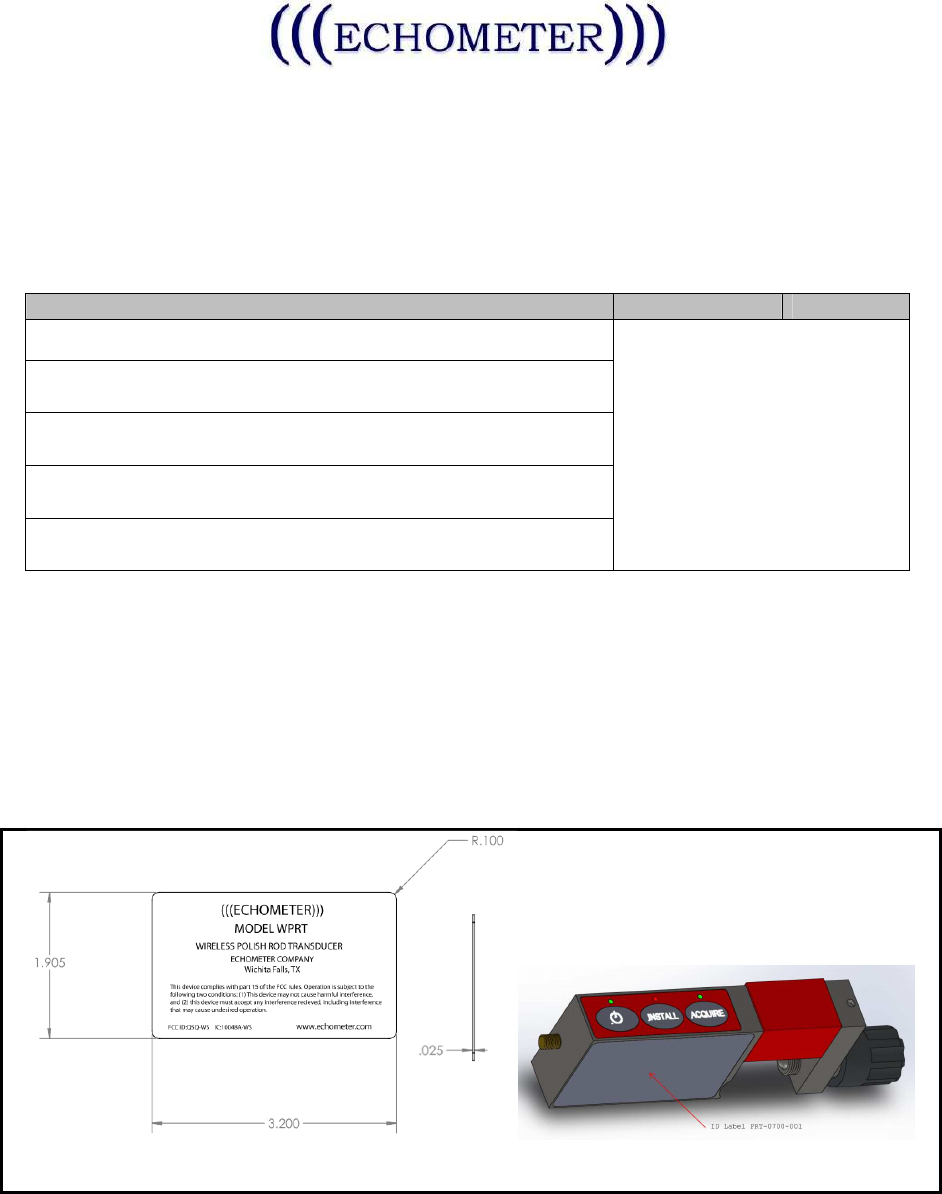
instructions. Table 2 includes the FCC Label design and intended installation location.
Sensor Model
# : Description
FCC
ID
IC ID
WPRT: Wireless Polished Rod Transducer
Q5Q-WS 10048A-WS
WHT: Wireless Horseshoe Transducer
WHT50K: Wireless Horseshoe Transducer - 50,000 pounds
WPT: Wireless Pressure Transducer
WGDA: Wireless General Data Acquisition
Table 1
All of the above utilize the same electronic PCB, Antenna, Battery, and run the same
Firmware. The PCB in each case is packaged in a fully enclosed stainless steel enclosure.
Each model includes a different transducer element wired to the PCB (such as a strain gauge,
or thermistor).
The instructions and pictures below depict the WPRT model. All other models will be similar
except for differences in the physical form factor.
Table 2
The Wireless Sensors are components of the Echometer Well Analyzer and designed to
be used with the Echometer WB100 Wireless Base, providing a wireless option for obtaining
data, (such as dynamometer, power and pressure/temperature). The data is analyzed by the

Wireless Sensor User Guide
Echometer Company
5001 Ditto Lane
Wichita Falls, TX 76302 24 Sep 2012
Echometer TAM software which runs on a PC/Notebook and utilized to provide analysis of well
performance. Please refer to the Echometer TAM Software User Manual for instructions
specific to software operation and to the Echometer WB100 Wireless Base User Manual for
instructions specific to that device.
• WARNING: Changes or modifications not expressly approved by the party responsible
for compliance could void the user’s authority to operate the equipment. This device
complies with part 15 of the FCC Rules. Operation is subject to the following two
conditions: (1) This device may not cause harmful interference, and (2) this device must
accept any interference received, including interference that may cause undesired
operation.
• NOTE: This equipment has been tested and found to comply with the limits for a Class A
digital device, pursuant to part 15 of the FCC Rules. These limits are designed to
provide reasonable protection against harmful interference when the equipment is
operated in a commercial environment. This equipment generates, uses, and can radiate
radio frequency energy and, if not installed and used in accordance with the instruction
manual, may cause harmful interference to radio communications. Operation of this
equipment in a residential area is likely to cause harmful interference in which case the
user will be required to correct the interference at the user’s expense.
• This equipment complies with the FCC RF radiation exposure limits set forth for an
uncontrolled environment. This equipment should be installed and operated with a
minimum distance of 20 centimeters between the antenna and your body.
• This Class A digital apparatus complies with Canadian ICES-003.
(Cet appareil numérique de la classe A est conforme à la norme NMB-003 du Canada)
• This device has been designed to operate with the antennas listed below. The specific
models listed or substitutes as specified below may be used.
o Pulse W1030
o Linx Tech ANT-2.4-CW-RAH-RPS: 2.4GHz
o Substitutes may be used, as long as they meet the 2.4GHz, 50Ω, <=2dBi gain,
RPSMA Male requirements.
Wireless Sensor User Guide
Echometer Company
5001 Ditto Lane
Wichita Falls, TX 76302 24 Sep 2012
WPRT Installation:
1. Clamp the Wireless Polished Rod Transducer (WPRT) to the polished rod on the oil
well below the carrier bar.
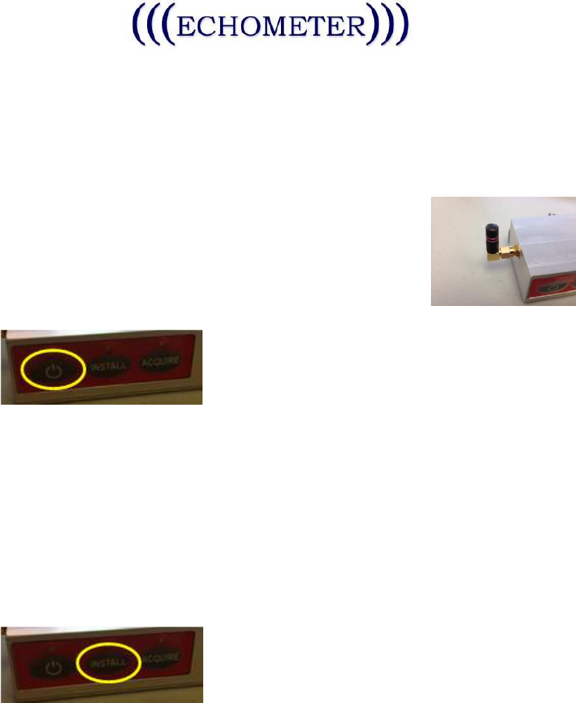
2. Install the antenna as shown. It is desirable that the antenna
be pointed upwards during operation.
3. Press the Power button on the WPRT as indicated below:
a. The LED above the Power button will proceed with the LED test, (illuminating
three green, and then three red LEDs).
b. Following the LED test, the Power button LED will flash a maximum of ten times
in rapid succession to indicate battery power. A fully charged battery will flash
ten times, with fewer flashes as the battery charge drops. Recharge the battery
when the flashes reduce to two.
c. Following the battery test, the Power LED will flash once per second to indicate
the WPRT is ready to proceed.
4. Press the Install button as shown below:
a. The Install LED will flash RED if the WPRT it too tight or flash GREEN if it is too
loose. Tighten or loosen the knob as needed until the LED illuminates solid
green.
Wireless Sensor User Guide
Echometer Company
5001 Ditto Lane
Wichita Falls, TX 76302 24 Sep 2012
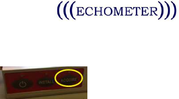
5. Press the Acquire button as shown below to initiate data acquisition. Use the TAM
software and instructions to complete the test.
Pressing ACQUIRE again will stop acquisition.
6. To turn off the WPRT, simply press the Power button for two seconds.