Ecolab FAS1521 PSS Door Monitor User Manual FCC Part 15
UltraClenz LLC. PSS Door Monitor FCC Part 15
Ecolab >
Contents
- 1. Manual 1 of 2
- 2. Manual 2 of 2
Manual 2 of 2

Certification Exhibit
FCC ID: Z9O-FAS1521
IC: 10060A-FAS1521
FCC Rule Part: 15.231
IC Radio Standards Specification: RSS-210
ACS Project: 14-2067
Manufacturer: UltraClenz, LLC
Models: FAS1521-01
User Manual
(Part 2 of 2)
3998 FAU Blvd. Suite 310 Boca Raton, FL 33431 Tel: 561-961-5585 Fax: 561-961-5587
DFU Document Title Here
4. Power-
On Self Test Sequence
When batteries are installed in the
PSS Doo
LED, single flash red LED, single flash green L
5. Entry-
Exit Functional Sequen
Door Entry (Compliant)
• Activate the hand s
anitizer dispense
• The PSS Door Monitor
will flash one
• Enter room
Door Exit (Compliant)
• Exit the room
• PSS Door Monitor red LED will flas
h
• Activate the hand sanitizer
• The green LED will flash once
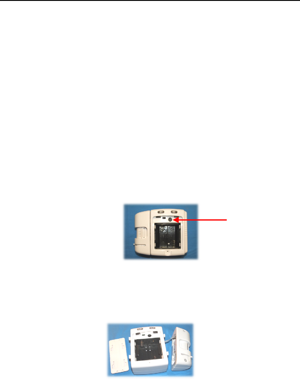
6. RS485 to Host Computer
The USB to RS485 Network
Interface Kit (pa
computer. (See Figures 3 and 5 for the locati
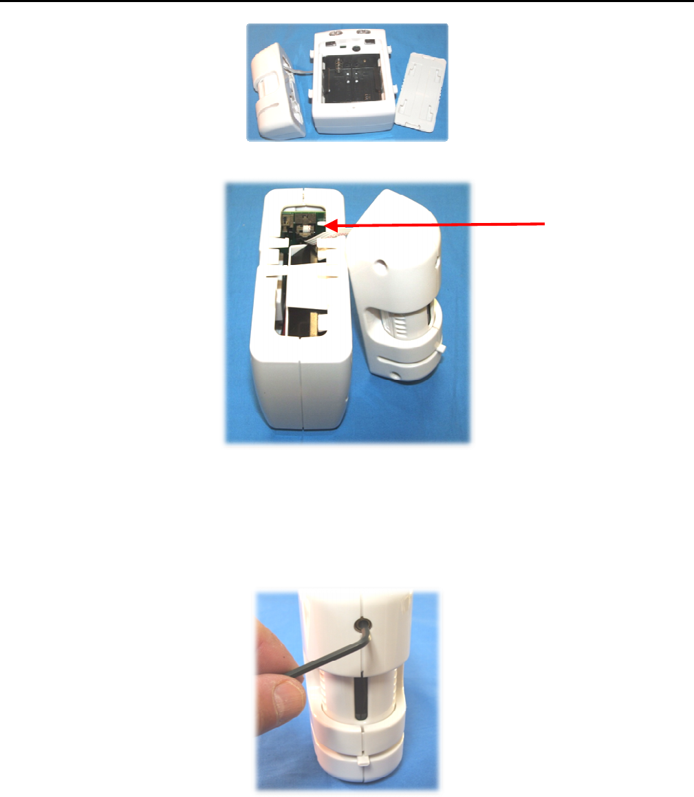
7.
Changing the PIR Sensor’s Po
The PIR Sensor can be swapped from the righ
(See Figures 6, 7and 8)
ence
Door Monitor
, a power on self test sequence initiates as fol
en LED, single flash red LED,
and three audible alarm beeps.
quences
enser
one green
LED
h
t (part number FAS1502
-00) is used to connect the
PSS Doo
cation of the
RS485 connector)
Figure 5. RS485 Din Connector
’s Position
right
side to the left
side depending on the door opening co
Figure 6. Right Side PIR
RS485
UltraClenz, LLC
Page 9
follows: single flash green
ps.
Door Monitor
to the Host
g configuration.
485 DIN Connector
DFU Document Title Here
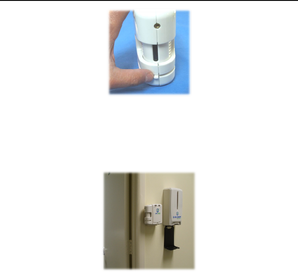
8. PIR Sensor Alignment
The sensor alignment
is adjusted by loosenin
adjustment tab at the bottom of the PIR sen
room’s door frame or entry path. (See Figure
Figure 7. Left Side PIR
Figure 8. PIR Connector
ening the 1/8” hex screw above the PIR window and by rota
sensor window
. It must be positioned
so that the PIR wind
gures 9 and 10)
Figure 9. Turret Locking Screw
PI
UltraClenz, LLC
Page 10
rotating
the turret with the
indow is aimed across the
PIR Sensor Connector
DFU Document Title Here
Figu
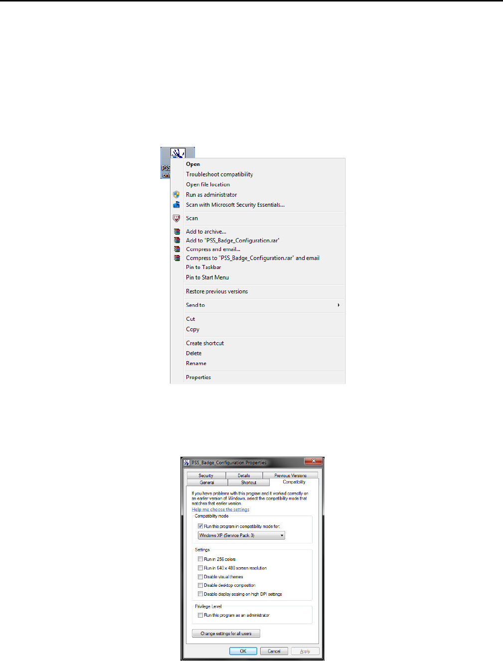
9. Door Mounting Location
The PSS Door Monitor
can be mounted on
opening. The mounting location of the
PSS
mounting height and horizontal mounting
button at the top and PIR sensor aiming ac
making sure the PRI sensor window is clear o
Figure 10.
PIR Sensor Alignment Tab
on the wall outside or inside
and
left or right side of th
PSS Door Monitor
can be at approximately
the same height
ing is
2 to 3 inches from entry path. Mount the
PSS Doo
g across
the door opening. The PSS Door Monitor
must be
ar of door molding and all o
ther obstructions (See Figure. 11
Figure 11. Mounting Example
UltraClenz, LLC
Page 11
f the
patient room’s door
ight as the hand dispenser
Door Monitor
with bypass
st be mounted off the wall
e. 11)
.

DFU Document Title Here
UltraClenz, LLC
Page 12
Appendix A - USB to RS485 Converter Installation
Introduction
The USB to RS485 Converter allows the connection of Windows PC based application software to an UltraClenz RS-485
enabled device. The USB to RS485 Converter connects directly to the host PC’s USB port via an A-B USB cable. Power for
this device is provided by the PC’s USB port so no external power source is required. The USB to RS485 Converter connects
to an RS-485 network via an RJ-11 connector or directly to an UltraClenz device’s data port via a 6-pin MiniDIN cable. Both
an RJ-11 and 6-pin MiniDIN connection are provided on the USB to RS485 Converter.
Host PC Requirements
• Windows XP, Windows 7 or Windows 8
• One Available USB High-Speed (2.0) or Full-Speed Port (3.0)
• 1MB of Available Hard Drive Space
• Minimum 128M of RAM
Installation
Follow the steps below to connect the USB to RS485 Converter to the host PC and load the USB driver. The following steps
are shown for Windows XP but Windows 7 and 8 are similar. It is possible that Windows 7 or Windows 8 may already have
the driver installed. If the Found New Hardware Wizard does not activate, then this is the case and the user may then skip
the installation section and go on to configuration section.
1. Locate an available USB port on the host PC
2. Attach the USB cable to the PC’s USB port
3. Attach the other end of the USB cable to the USB to RS485 Converter
4. Window’s “Found New Hardware” Wizard will activate automatically
5. In the Wizard, select “No, not this time” then click Next
6. Insert the USB driver CD into the CD drive
7. Select “Install software automatically (Recommended)” then click Next
8. Click Finish to complete the driver installation
After clicking finish, the “Found New Hardware” Wizard will activate again to install the COM port emulation driver. The
procedure is the same as that above for installing the USB driver.
The above steps need only be performed the first time the USB to RS485 Converter is attached to the host PC. Once the
drivers are installed, the host PC will always recognize the USB device.

DFU Document Title Here
UltraClenz, LLC
Page 13
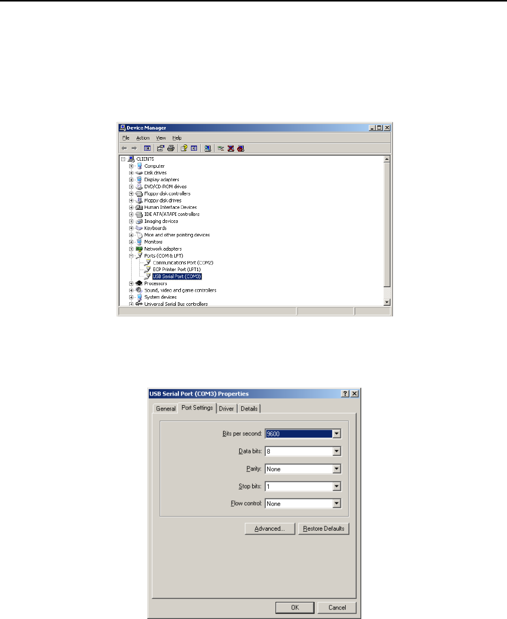
Configuration
The USB to RS485 Converter will emulate a serial (COM) port on the host PC. It will be necessary to determine which COM
port the USB driver has selected. To do this, follow the steps below.
1. Open the Control Panel
2. Click on Performance and Maintenance (only if Control Panel is setup for Category View)
3. Click on System
4. Click on the Hardware tab
5. Click the Device Manager button
6. Select View -> Devices by Type from the menu
7. Expand Ports in the tree view
The device appears as an additional COM port with the label “USB Serial Port” and the assigned COM port in parentheses.
Example: USB Serial Port (COM3)
Make a note of the assigned COM port and select it when running UltraClenz software.
If the assigned COM port is not desired, it can be changed to any other available port by following the steps below.
1. Double click on USB Serial Port in the Device Manager tree view
2. Click on Port Settings tab
3. Click the Advanced button
4. Select a different COM port from the COM Port Number drop down menu
5. Click the OK button
NOTE:
The driver will assign each USB port to a unique COM port. Please be aware that using different USB ports will require
changing the selected COM port in the PC application software.
DFU Document Title Here
UltraClenz, LLC
Page 14
Appendix B - Windows Compatibility Mode
UltraClenz PC application software is currently developed under Windows XP. For it to perform correctly under newer
versions of Windows, Windows Compatibility Mode must be enabled after the software has been installed. Once
compatibility mode has been enabled, nothing more is required. The software will automatically run in compatibility mode
each time it is launched.
Perform the following steps to put installed UltraClenz PC application software into Windows Compatibility mode.
Locate the folder/directory where the software executable (.exe) is installed and right click on the executable’s icon.
Choose “Properties” from the bottom of the context menu that appears.
After choosing “Properties” from the context menu, a window will appear displaying the different properties of the
application organized in tabs. Select the “Compatibility” tab, check the “Run this program in compatibility mode for:”
checkbox, then select Windows XP SPS 3 from the drop down menu and click the OK button.
DFU Document Title Here
UltraClenz, LLC
Page 15
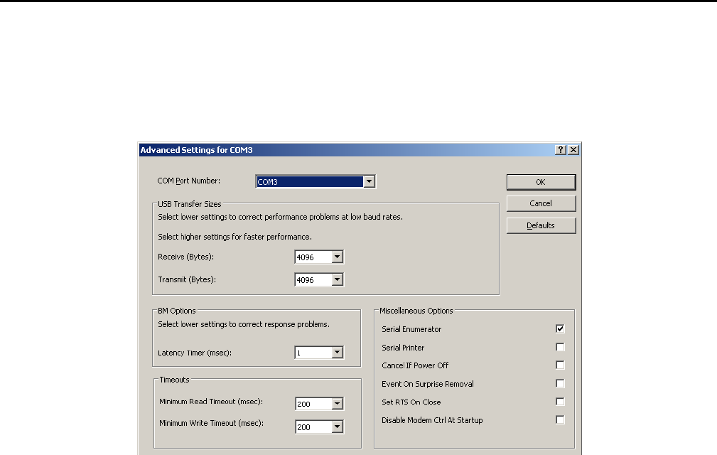
Appendix C - COM Port Performance
If communication performance issues are observed, it will be necessary to “tweak” the COM port’s properties. The
following steps will configure the COM port for reliable communications.
1. Connect the USB to RS485 Converter to an available USB port. Then, go to Device Manager, expand “Ports” and
double click “USB Serial Port”.
2. In USB Serial Port Properties, select the “Port Settings” tab and click the “Advanced” button.
DFU Document Title Here
UltraClenz, LLC
Page 16
3. In Advanced Settings, change “Latency Timer” to 1. Change both “Minimum Read Timeout” and “Minimum Write
Timeout” to 200. Then click the “OK” button.
4. For COM port changes to take effect, Windows 7 and 8 may require a reboot (Windows XP does not).

DFU Document Title Here
UltraClenz, LLC
Page 17
Appendix D - Certification and Safety Approvals
FCC Statement
NOTE: This equipment has been tested and found to comply with the limits for a Class B digital device, pursuant to Part 15 of the FCC
Rules. These limits are designed to provide reasonable protection against harmful interference in a residential installation. This
equipment generates, uses, and can radiate radio frequency energy and, if not installed and used in accordance with the instructions,
may cause harmful interference to radio communications. However, there is no guarantee that interference will not occur in a
particular installation. If this equipment causes harmful interference to radio or television reception, which can be determined by
turning the equipment off and on, the user is encouraged to try and correct the interference by one or more of the following
measures:
• Reorient or relocate the receiving antenna.
• Increase the separation between the equipment and receiver
• Connect the equipment into an outlet on a circuit different from that to which the receiver is connected.
• Consult the dealer or an experienced radio/TV technician for help.
WARNING: Changes or modifications not expressly approved by UltraClenz, LLC could void the user’s authority to operate the
equipment.
RF Exposure:
“This equipment complies with FCC radiation exposure limits set forth for an uncontrolled environment. This equipment should be
installed and operated with minimum distance 20cm between the radiator and your body. This transmitter must not be co-located or
operating in conjunction with any other antenna or transmitter.”
Industry Canada
Under Industry Canada regulations, this radio transmitter may only operate using an antenna of a type and maximum
(or lesser) gain approved for the transmitter by Industry Canada. To reduce potential radio interference to other users,
the antenna type and its gain should be so chosen that the equivalent isotropically radiated power (e.i.r.p.) is not more
than that necessary for successful communication.
Conformément à la réglementation d'Industrie Canada, le présent émetteur radio peut fonctionner avec une antenne
d'un type et d'un gain maximal (ou inférieur) approuvé pour l'émetteur par Industrie Canada. Dans le but de réduire les
risques de brouillage radioélectrique à l'intention des autres utilisateurs, il faut choisir le type d'antenne et son gain de
sorte que la puissance isotrope rayonnée équivalente (p.i.r.e.) ne dépasse pas l'intensité nécessaire à l'établissement
d'une communication satisfaisante.
This device complies with Industry Canada license-exempt RSS standard(s). Operation is subject to the following two
conditions: (1) this device may not cause interference, and (2) this device must accept any interference, including
interference that may cause undesired operation of the device.
Le présent appareil est conforme aux CNR d'Industrie Canada applicables aux appareils radio exempts de licence.
L'exploitation est autorisée aux deux conditions suivantes: (1) l'appareil ne doit pas produire de brouillage, et (2)
l'utilisateur de l'appareil doit accepter tout brouillage radioélectrique subi, même si le brouillage est susceptible d'en
compromettre le fonctionnement.

DFU Document Title Here
UltraClenz, LLC
Page 18
Appendix E - Warranty
This device is warranted against defective materials and workmanship for two years from the date of purchase.
Equipment covered by this warranty will be repaired or replaced in the United States and Canada, WITHOUT CHARGE,
except for shipping and handling, by our Factory Service Center.
When returning equipment for warranty service, you must first call your distributor’s Warranty Service Department for
your Return Merchandise Authorization Number (RMA). The RMA must be on your return label and the shipping charges
must be pre-paid and a copy of your receipt must be enclosed. Equipment should be returned to UltraClenz Customer
Service, 1201 Jupiter Park Drive, Jupiter, FL 33458.
This warranty covers all defects incurred from normal use of the equipment and does not apply in the following cases:
a. Loss or damage to the equipment due to abuse, mishandling, accident or failure to follow installation or use
instructions.
b. If the equipment is defective as a result of leaking batteries.
c. If the equipment has been serviced or modified by someone other than our authorized agents.
THE AFOREMENTIONED IS IN LIEU OF ALL WARRANTIES, EXPRESSED OR IMPLIED, INCLUDING BUT NOT LIMITED TO, ANY
WARRANTY OF MERCHANTABILITY OR OF FITNESS FOR ANY PARTICULAR PURPOSE. IN NO EVENT SHALL THE VENDOR BE
LIABLE FOR CONSEQUENTIAL, INCIDENTAL, INDIRECT OR SPECIAL DAMAGES OR LIABILITY, TRANSPORTATION,
INSTALLATION OR SUBSTITUTION COSTS, DELAYS, OR FOR ANY OTHER DAMAGES, COSTS, OR EXPENSES INCURRED,
IRRESPECTIVE OF HOW THEY OCCUR. THIS WARRANTY SHALL NOT EXTEND TO ANY OTHER PERSON OTHER THAN THE
ORIGINAL PUCHASER OF THIS EQUIPMENT OR THE PERSON FOR WHOM IT WAS PURCHASED AS A GIFT.
This warranty gives you specific legal rights, and you may also have other rights, which may vary from state to state. This
warranty is given with respect to equipment purchased in the United States.