Ecolab FAS1521 PSS Door Monitor User Manual FCC Part 15
UltraClenz LLC. PSS Door Monitor FCC Part 15
Ecolab >
Contents
- 1. Manual 1 of 2
- 2. Manual 2 of 2
Manual 1 of 2

Certification Exhibit
FCC ID: Z9O-FAS1521
IC: 10060A-FAS1521
FCC Rule Part: 15.231
IC Radio Standards Specification: RSS-210
ACS Project: 14-2067
Manufacturer: UltraClenz, LLC
Models: FAS1521-01
User Manual
(Part 1 of 2)
3998 FAU Blvd. Suite 310 Boca Raton, FL 33431 Tel: 561-961-5585 Fax: 561-961-5587
PSS Door Monitor
PSS Door Monitor
User Guide
(FAS1521)
DOC1059
Revision 2
UltraClenz, LLC

DFU Document Title Here
UltraClenz, LLC
Page 1
Table of Contents
`Abstract ...................................................................................................................................................................................... 3
Revision History ........................................................................................................................................................................... 3
Terms, Acronyms and Abbreviations ........................................................................................................................................... 3
1. PSS Door Monitor Features ..................................................................................................................................................... 4
1.1 Component Descriptions - Front View (See Figure 1) ........................................................................................................ 4
1.2 Component Descriptions - Back View (See Figure. 2) ........................................................................................................ 5
2. PSS Door Monitor Led Functionality ........................................................................................................................................ 5
2.1 Hand Hygiene Compliance Warning (Red LED) .................................................................................................................. 5
2.2 Hand Hygiene Compliant - Enter or Exit Area (Green LED) ................................................................................................ 5
2.3 Low Battery Indicator (Red LED) ........................................................................................................................................ 5
2.4 Dead battery Indicator (Red LED) ...................................................................................................................................... 5
3. PSS Door Monitor Configuration Software .............................................................................................................................. 6
3.1 PSS Door Monitor Configuration Software Menu (See Figure.4) ...................................................................................... 6
3.2 Configuration Options........................................................................................................................................................ 7
3.2.1 Operating Mode .......................................................................................................................................................... 7
3.2.2 Mounting Location ...................................................................................................................................................... 7
3.2.3 Interface Options ........................................................................................................................................................ 7
3.2.4 Bypass Mode ............................................................................................................................................................... 7
3.2.5 Alarm Timeout (Increment or Decrement) ................................................................................................................. 7
3.2.6 Pass-through Timeout (Increment or Decrement) ..................................................................................................... 7
3.2.7 Room Entry Counts (Uploaded from the PSS Door Monitor) ..................................................................................... 7
3.2.8 Room Exit Counts (Uploaded from the PSS Door Monitor) ........................................................................................ 8
3.3 Firmware Version (Uploaded from the PSS Door Monitor) ............................................................................................... 8
3.4 Device Address (Uploaded from the PSS Door Monitor) ................................................................................................... 8
3.5 Upload Configuration ......................................................................................................................................................... 8
3.6 Download Configuration .................................................................................................................................................... 8
4. Power-On Self Test Sequence .................................................................................................................................................. 9
5. Entry- Exit Functional Sequences ............................................................................................................................................. 9
6. RS485 to Host Computer ......................................................................................................................................................... 9
7. Changing the PIR Sensor’s Position .......................................................................................................................................... 9
8. PIR Sensor Alignment ............................................................................................................................................................. 10
9. Door Mounting Location ........................................................................................................................................................ 11
Appendix A - USB to RS485 Converter Installation .................................................................................................................... 12
Appendix B - Windows Compatibility Mode .............................................................................................................................. 14
Appendix C - COM Port Performance ........................................................................................................................................ 15
Appendix D - Certification and Safety Approvals ....................................................................................................................... 17
FCC Statement ....................................................................................................................................................................... 17

DFU Document Title Here
UltraClenz, LLC
Page 2
Industry Canada ..................................................................................................................................................................... 17
Appendix E - Warranty ............................................................................................................................................................... 18
Figures
Figure 1.
PSS Door Monitor Front View ................................................................................................................................ 4
Figure 2.
PSS Door Monitor Back View ................................................................................................................................. 4
Figure 3.
USB to RS485 Converter Cable Connection ........................................................................................................... 6
Figure 4.
Configuration Settings Screen ................................................................................................................................ 8
Figure 5.
RS485 Din Connector ............................................................................................................................................. 9
Figure 6.
Right Side PIR ......................................................................................................................................................... 9
Figure 7.
Left Side PIR ......................................................................................................................................................... 10
Figure 8.
PIR Connector ...................................................................................................................................................... 10
Figure 9.
Turret Locking Screw ............................................................................................................................................ 10
Figure 10.
PIR Sensor Alignment Tab .................................................................................................................................... 11
Figure 11.
Mounting Example ............................................................................................................................................... 11

DFU Document Title Here
UltraClenz, LLC
Page 3
Abstract
This document provides a description of the features of the PSS Door Monitor unit in order to familiarize the user with the
unit. Also, a brief description of the PSS Door Monitor functions are given, followed by instructions on how to install the
unit.
Revision History
Revision Date By Description
0 01/12/14 TRS Initial Release
1 05/14/14 AJS/JH/TRS Updated Pictures and Text to Reflect the New Trade Name, Changed to New Format
2 12/03/14 DLS Added Appendix A-C, updated configuration software, made corrections to text and format
Terms, Acronyms and Abbreviations
GUI Graphical User Interface
HCW Health Care Worker
PIR Passive Infrared
POST Power On Self-Test
DFU Document Title Here
1. PSS Door Monitor Features
The PSS Door Monitor
is designed to track healthcare worker
room, by recording
whether or not a soap or sanitizer dispenser was used during patient room
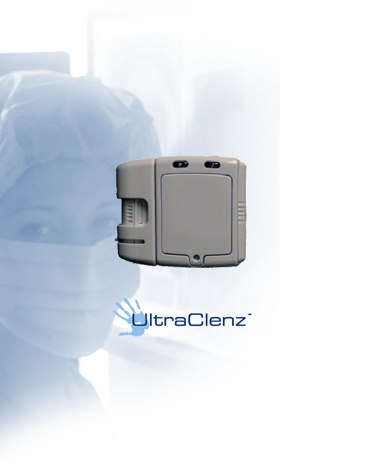
1.1 Component Descriptions -
Front View (See Figure 1)
Removable Side Cover
This allows the user to change the
PSS Door Monitor
item 1).
Battery Compartment
Remove front cover to allow access to the battery compartment.
battery polarity is s
hown in the battery box (See Figure.1 item 2).
RS485 Data Port
The RS485 Communications Port din connector is used to connect the
Communications port is used to configure
5) Audible Alert
3) RS485 Data Port
2) Battery Compartment
1) Removable Side Cover
4) Green & Red LEDs
is designed to track healthcare worker
hand
hygiene compliance with respect to a specific hospital
whether or not a soap or sanitizer dispenser was used during patient room
entries and exits.
Figure 1. PSS Door Monitor Front View
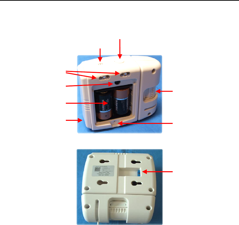
Figure 2. PSS Door Monitor Back View
Front View (See Figure 1)
PSS Door Monitor
configuration from right side to left
side room entry (See Figure 1
Remove front cover to allow access to the battery compartment.
Insert 2 quality D cell
alkaline
hown in the battery box (See Figure.1 item 2).
The RS485 Communications Port din connector is used to connect the
PSS Door Monitor
to a Host computer.
Communications port is used to configure
the PSS Door Monitor, Upload and Download
data (See Figure 1 item 3)
6) Bypass Button
5) Audible Alert
8) Removable Front
Cover
7) Adjustable Sensor
9) Dispenser Connector
UltraClenz, LLC
Page 4
hygiene compliance with respect to a specific hospital
entries and exits.
side room entry (See Figure 1
alkaline
batteries. Note the
to a Host computer.
The
data (See Figure 1 item 3)
.
8) Removable Front
Cover
7) Adjustable Sensor
9) Dispenser Connector

DFU Document Title Here
UltraClenz, LLC
Page 5
Green & Red LEDs
The green and red LEDs provide visual feedback to the healthcare worker (See Figure.1 item 4).
GREEN: The single green led flash indicates a door entry or exit with compliance.
RED: Indicates a wash compliance warning.
Audible Alert
The audible alert makes a beeping sound that is used to give feedback to the healthcare worker (See Figure.1 item 5).
Bypass Button
The bypass mode must be enabled in the PSS Door Monitor configuration software, see section 3.0 PSS Door Monitor
Configuration (Figure 4) for this function to work. The override button is used to stop the PSS Door Monitor from
sensing for a programmed time period (See Figure 1 item 6). The override mode can be used by housekeeping staff to
prevent multiple non-compliance events while performing routine room maintenance.
The Override Time can be set as follows:
Momentarily depress the override button once for a 30-second default countdown. The override button grace period
can be changed from the PSS Door Monitor configuration software (See Figure 4).
Adjustable Sensor
The Sensor can be adjusted to select the correct PIR angle. The sensor adjustment is done at the time of installation to
optimize door entry and exit sensing (See Figure 1 item 7).
Front Cover
Removable front cover and screw assembly (See Figure. 1 item 8).
1.2 Component Descriptions - Back View (See Figure. 2)
Dispenser Connector
The dispenser plugs into this connector of the PSS Door Monitor (See Figure. 2 item 9). The PSS Door Monitor is
attached to a dispenser via an interface connector and counts all patient room entries and exits with dispense
(compliant event), without dispense (non-compliant event) and total room entries and exits.
2. PSS Door Monitor Led Functionality
2.1 Hand Hygiene Compliance Warning (Red LED)
The hand hygiene compliance LED warning will flash and the audible alarm will beep to alert the HCW entering or
exiting the patient room. The alert will continue until the HCW has sanitized or the preset pass-through timer has timed
out (see PSS Door Monitor Configuration Software). If the pass-through timer reaches the set terminal count, the event
will be recorded and the red indicator LED will stop flashing.
2.2 Hand Hygiene Compliant - Enter or Exit Area (Green LED)
When a HCW activates the dispenser, the hand hygiene compliant LED will flash and the audible alarm will beep once.
The event will be counted only if the HCW enters or exits the patient room. The PSS Door Monitor will not record an
event if dispense activation occurs without a door entry, however the beeps will still occur.
2.3 Low Battery Indicator (Red LED)
The PSS Door Monitor will produce a single red LED flash every 3 seconds indicating a low battery condition.
2.4 Dead battery Indicator (Red LED)
The PSS Door Monitor will produce a double red LED flash every 3 seconds indicating a dead battery condition.

DFU Document Title Here
3. PSS Door Monitor
Configuration Software
The PSS Door Monitor
Configuration Software is a graphical user interface (
hardware and software parameters for
room layouts.
Before installing the
PSS Door Monitor
RS485 to USB serial
Interface driver. The RS485 to USB Network Interface kit (part number FAS1502
interface, driver CD, 2 communication cables and
computer’s USB port.
The second cable connects the
port DIN connector (
See Figure 3 for the Communication Port locations).
Figure 3.
3.1 PSS Door Monitor
Configuration Software
File
Exit - Closes the PSS Door Monitor
Configuration Software
Setup
Scan for COM Port -
Note, the PSS Door Monitor must be connected to the host PC
port until the PSS Door Monitor is found.
Tools
Reset Counts -
Reset all counts to zero
appear, to prevent inadvertent resets.
To
Configuration Software
Configuration Software is a graphical user interface (
GUI), which allows the installer to set
hardware and software parameters for
desired operation. The PSS Door Monitor
can be configured for a variety of
PSS Door Monitor
Configuration Software on the Host computer, the u
ser must first install the
Interface driver. The RS485 to USB Network Interface kit (part number FAS1502
interface, driver CD, 2 communication cables and
users guide. The first cable connects the
serial
The second cable connects the
serial Interface to the PSS Door Monitor
’s
See Figure 3 for the Communication Port locations).
Figure 3.
USB to RS485 Converter Cable Connection
Configuration Software
Menu (See Figure.4)
Configuration Software
Note, the PSS Door Monitor must be connected to the host PC
.
The software will scan each COM
port until the PSS Door Monitor is found.
Reset all counts to zero
. A confirmation message "Do you r
eally want to set the counts to zero" will
RS485 D
IN
Connector & Cable
To
Commputer’s USB Port
UltraClenz, LLC
Page 6
GUI), which allows the installer to set
-up the
can be configured for a variety of
ser must first install the
Interface driver. The RS485 to USB Network Interface kit (part number FAS1502
-00) includes the
serial
Interface to the host
’s
RS485 communications
The software will scan each COM
eally want to set the counts to zero" will

DFU Document Title Here
UltraClenz, LLC
Page 7
3.2 Configuration Options
The following configurations setting are set during the installation process only. These settings can only be configured
thru the RS485 to USB network Interface.
3.2.1 Operating Mode
• Normal PIR - Select when PSS Door Monitor is mounted near a patient room door.
• Counter Only - Select when PSS Door Monitor is mounted inside of a patient room but not near a door.
3.2.2 Mounting Location
• Outside of Room - Select when PSS Door Monitor is mounted on the outside of a patient room.
• Inside of Room - Select when PSS Door Monitor is mounted on the inside of a patient room.
NOTE: The User must select the correct mounting location of the PSS Door Monitor. The PSS Door Monitor will not
function properly if the "Mounting Location" is incorrect.
3.2.3 Interface Options
• Bypass Mode Enabled - Checked enables, unchecked disables the override button
• LED(s) Enabled - Checked enables the red and green LEDs, unchecked disables red and green LEDs
• Entry Alarm Enabled - Checked enables, unchecked disables only the audible alarm on entry.
• Exit Alarm Enabled - Checked enables, unchecked disables only the audible alarm.
3.2.4 Bypass Mode
This enables and disables the Override Button which allows room entry without setting and alarm activation. Press
the Bypass button once and the PSS Door Monitor will sound an audible alarm and the green LED will flash until the
selected Bypass time is complete. When the Bypass time is complete, the audible alarm will sound once and the Red
LED will flash once.
3.2.5 Alarm Timeout (Increment or Decrement)
The default is 5 seconds. The user may increment the alarm timeout as needed. The alarm timeout is the amount of
time between exit or entry detection and a dispense activation. If the dispense activation occurs within the alarm
timeout period, the event will be counted as a compliant event (entry or exit). If the dispense activation occurs after
the alarm timeout period or there is no dispense activation, the event will be counted as a non-compliant event
(entry or exit).
3.2.6 Pass-through Timeout (Increment or Decrement)
The default is 30 seconds. The user may increment the pass-through timeout as needed. The pass-through timeout
is the amount of time a HCW has between a dispense activation and a room Entry or Exit. After a HCW has entered
or exited a room, the timer will reset. If a HCW enters or exits after the pass-through timeout period, then the HCW
must activate the dispenser again or an alarm timeout will occur which will cause a non-compliant event to be
counted.
3.2.7 Room Entry Counts (Uploaded from the PSS Door Monitor)
• With Dispense
• Without Dispense
• Total Room Entries
NOTE: It is up to the user to keep track of the date and unit address when counts are uploaded from the PSS Door
Monitor, because the events are not time stamped. The counts will be uploaded and saved as a CSV file that may be
imported into spreadsheet software for data analysis.

DFU Document Title Here
UltraClenz, LLC
Page 8
3.2.8 Room Exit Counts (Uploaded from the PSS Door Monitor)
• With Dispense
• Without Dispense
• Total Room Exits
NOTE: It is the user’s responsibility to keep track of the date and unit address when counts are uploaded from the
PSS Door Monitor, because the events are not time stamped. The counts will be uploaded and saved as a CSV file
that may be imported into spreadsheet software for data analysis.
3.3 Firmware Version (Uploaded from the PSS Door Monitor)
When the PSS Door Monitor is connected, the firmware version will be displayed.
3.4 Device Address (Uploaded from the PSS Door Monitor)
When the PSS Door Monitor is connected, the device address will be displayed. The device address is unique for each
PSS Door Monitor.
3.5 Upload Configuration
This will upload all of the configuration selections to the PSS Door Monitor unit. Menu selections that are available for
reconfiguration are Interface Options, Mounting Location, Alarm Time, Room Entry/Exit Time and Bypass Timeout
(See Figure 4).
3.6 Download Configuration
This will download the room counts, configuration selections, firmware version and device address from the PSS Door
Monitor unit.
Figure 4. Configuration Settings Screen