Edgecore Networks SMC2891WAN 802.11a/b/g/n Outdoor Dual Band Wireless Access Point User Manual Quick Start Guide
Edgecore Networks Corporation 802.11a/b/g/n Outdoor Dual Band Wireless Access Point Quick Start Guide
Contents
- 1. User Manual - IG
- 2. User Manual - MG
- 3. User Manual - QSG
- 4. User Manual - Statements
User Manual - QSG
– 1 –
Quick Start Guide
802.11a/b/g/n Outdoor Dual-Band Wireless Access Point
SMC2890W-AN / SMC2891W-AN
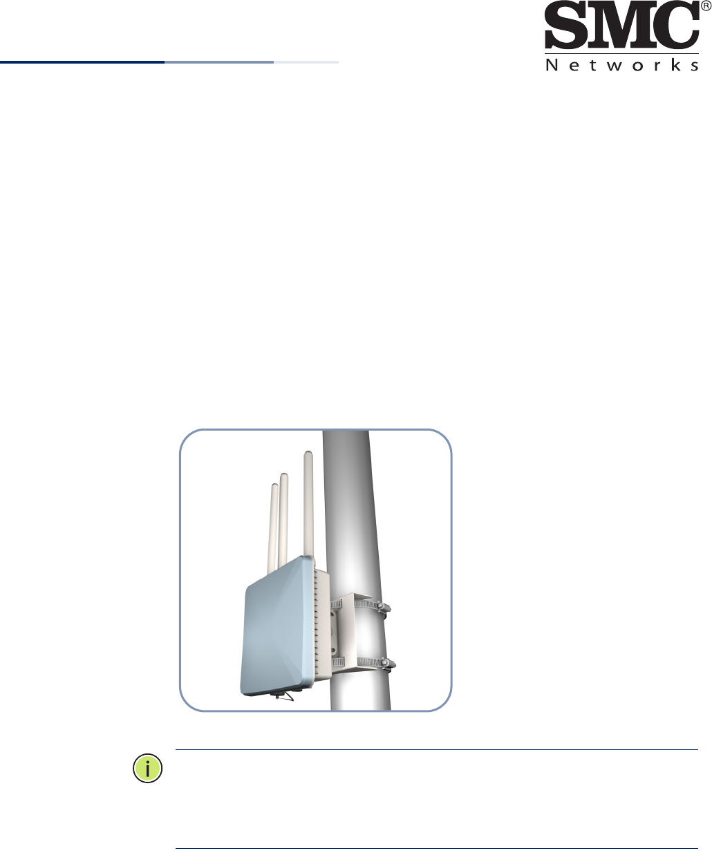
The SMC2890W-AN and SMC2891W-AN are dual-band IEEE 802.a/b/g/n access
points (APs) that are housed in a weatherproof enclosure for mounting outdoors.
The units include a mounting bracket for attaching to a 1.5 to 6-inch pole and can
be powered through their Ethernet cable connection from a power injector module
that is installed indoors.
◆SMC2890W-AN — Provides four external antenna connectors only.
◆SMC2891W-AN — Provides three external antenna connectors and one built-
in 5 GHz high-gain antenna.
Note:
For detailed AP installation information, refer to the Installation Guide,
which is on the Documentation CD included with the AP.
Note:
For Safety and Regulatory information, refer to the Safety and Regulatory
Information document included with the AP.
E012013-CS-R01
150200000599A
www.smc.com
Quick Start Guide
– 2 –
Follow the steps in this guide to install the AP in your network.
Caution:
The planning and installation of the AP requires professional personnel
that are trained in the installation of radio transmitting equipment. The user is
responsible for compliance with local regulations concerning items such as
antenna power, use of lightning arrestors, grounding, and radio mast or tower
construction. Therefore, it is recommended to consult a professional contractor
knowledgeable in local radio regulations prior to equipment installation.
1. Unpack the AP Unpack the AP and check the package contents.
◆SMC2890W-AN or SMC2891W-AN Outdoor Access Point
◆Bracket Mounting Kit for pole mounting
◆PoE power injector with power cord—either US, Continental Europe or UK
◆Console cable (RJ-45 to DB-9)
◆Waterproof RJ-45 port cover
◆Quick Start Guide
◆Regulatory and Safety Information
◆Documentation CD — includes Installation Guide and Management Guide
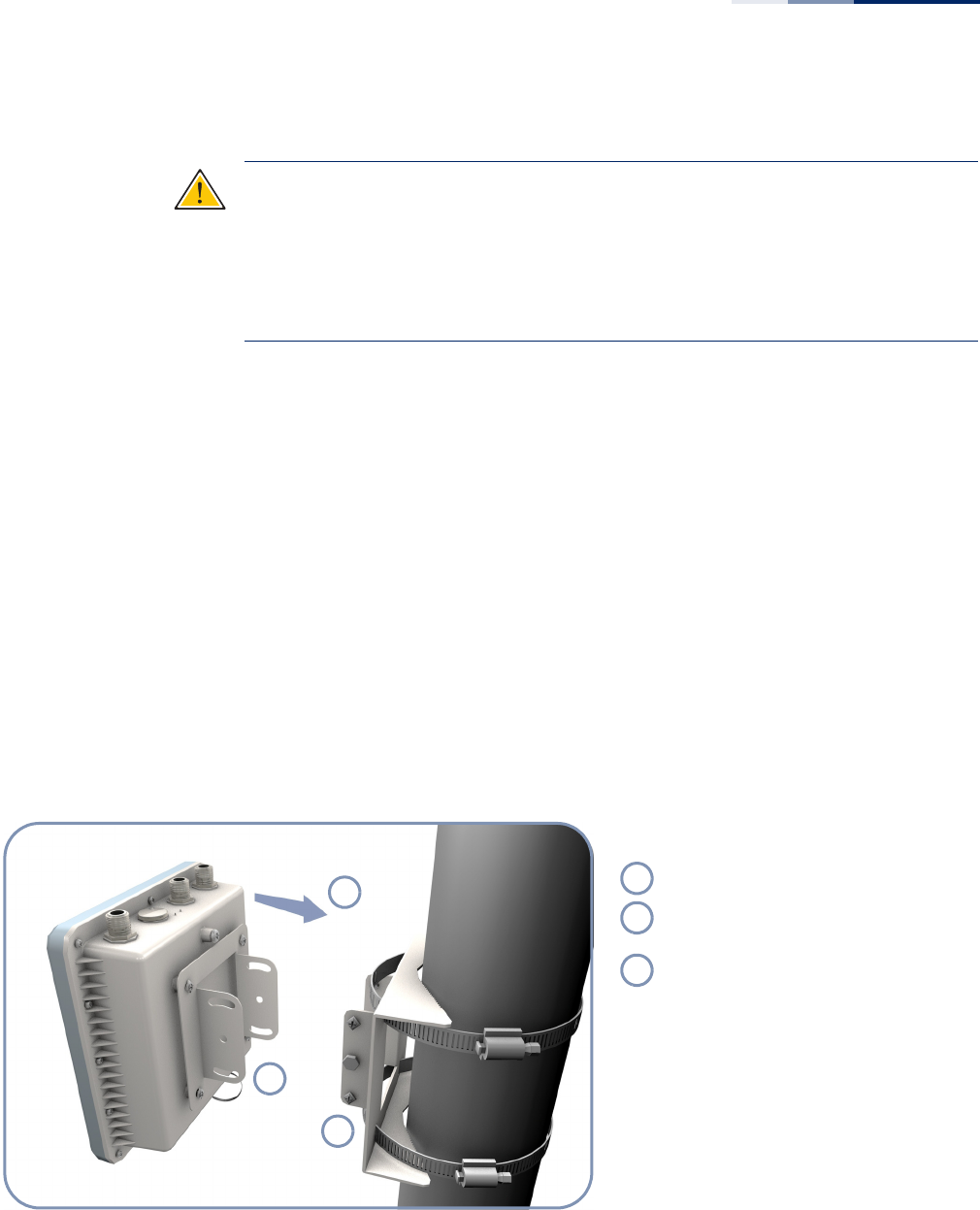
2. Mount the AP After planning your installation, mount the unit on a pole, mast, or tower using the
mounting bracket. Also install the external antennas required for your wireless
service.
.
Pole Mounting
Attach one part of the bracket to the AP.
Attach the other parts of the bracket to
the pole.
Link the two bracket parts together to
secure the AP to the pole.
1
2
3
1
2
3
Quick Start Guide
– 3 –
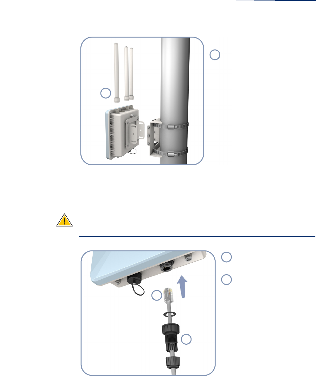
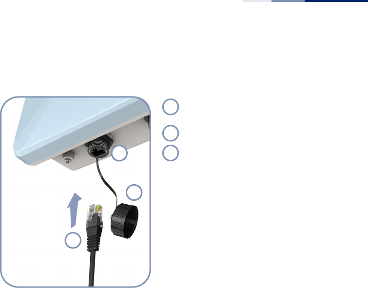
3. Connect Cables Connect outdoor-rated Ethernet cable to the RJ-45 port and a grounding wire to
the unit.
Caution
:
Be sure that grounding is available and that it meets local and national
electrical codes. Grounding the AP must be performed by a professional installer.
1
.
Attach External Antennas
Connect antennas either directly to
the AP’s N-type connectors, or use
RF coaxial cable provided in the
antenna package.
1
1
2
Connect outdoor-rated
Category 5e or better cable to
the RJ-45 port.
Be sure to use the waterproof
cover on the port.
1
2
Quick Start Guide
– 4 –
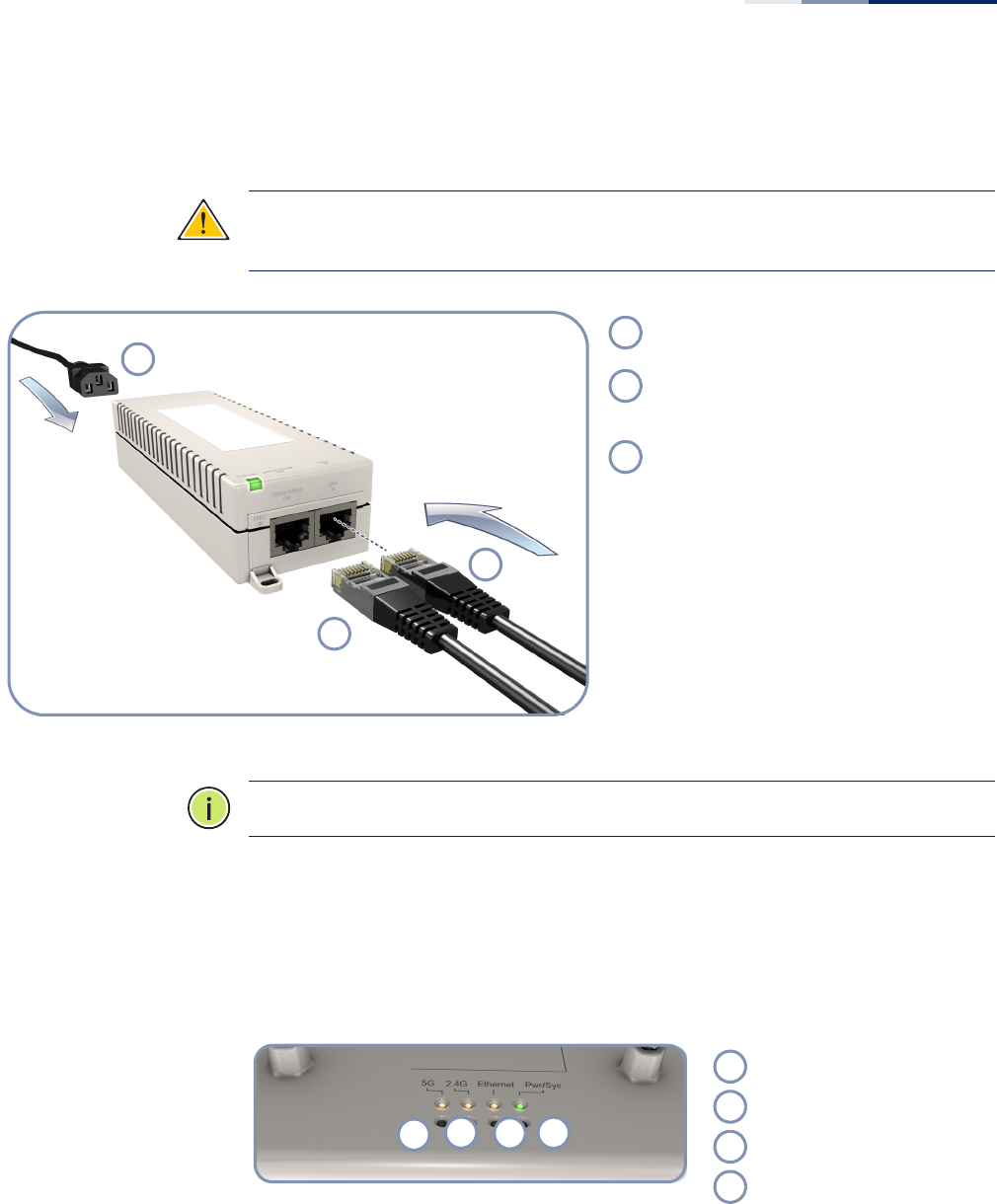
4. Connect Power Install the PoE power injector indoors. Connect the power injector to the Ethernet
cable, a local LAN switch, and an AC power source.
Caution:
The power injector module is designed for indoor use only. Never mount
the power injector outside with the AP unit.
Note
:
Connecting the Ethernet cable to the injector module powers on the unit.
5. Verify AP Operation Verify basic AP operation by checking the system LEDs.
The Pwr/Sys LED should be on green, the Ethernet LED on/blinking orange, and the
2.4G and 5G LEDs on/blinking orange.
1
2
3
Connect the power cord to a nearby AC
power source (100-240 VAC, 50/60 Hz).
Connect the Ethernet cable from the AP to
the “DATA & POWER OUT” port on the
power injector.
Connect Ethernet cable from the “DATA IN”
port on the power injector to a LAN switch.
1
2
3
1234
5 GHz link/activity LED.
2.4 GHz link/activity LED.
LAN link/activity LED.
Power/system LED.
1
2
3
4
Quick Start Guide
– 5 –
6. Connect to the
Console Port
To make initial configuration changes to the AP, connect a PC to the AP’s console
port using the included console cable.
From a PC running VT-100 terminal emulator software, use the following settings:
◆Baud rate — 115,200 bps
◆Character Size — 8 Characters
◆Parity — None
◆Stop bit — One
◆Data bits — 8
◆Flow control — none
Log in to the command-line interface (CLI) using default settings:
◆Login Name — admin
◆Password — null (there is no default password)
For information on AP configuration and CLI commands, refer to the Management
Guide, which is on the Documentation CD included with the AP.
Remove the waterproof cover from the
Console port.
Use the included RJ-45-to-DB-9 console cable.
Connect to the AP’s console port.
1
2
3
1
2
3

Quick Start Guide
– 6 –
Hardware Specifications
Item Specification
Chassis Specifications
Size W x D x H: 195 x 190 x 74 mm (7.68 x 7.48 x 2.91 inches)
Weight 1.7 kg (3.75 lbs), unit without bracket or external antennas
Temperature Operating: -10 °C to 60 °C (-14 °F to 140 °F)
Storage: -20 °C to 70 °C (-4 °F to 158 °F)
Humidity Operating: 10% to 95% (non-condensing)
Wind Velocity Operational: 100 MPH (Miles per hour) / 44 mps
Survival: 150 MPH / 66 mps
Network Interfaces
Ports One RJ-45 Port: 1000BASE-T, PoE (PD)
2.4 GHz Radio IEEE 802.11b/g/n
5 GHz Radio IEEE 802.11a/n
Radio Frequencies 2400 ~ 2483.5 MHz
2412 ~ 2472 MHz
5745 ~ 5825 MHz (China)
5180 ~ 5320 MHz (ETSI)
5500 ~ 5700 MHz (ETSI)
Power Supply Specifications
PoE Input Power 38~57 VDC
Power Consumption 25.5 W maximum for IEEE 802.3at
12.95 W maximum for IEEE 802.3af
Power Injector Module 100-240 VAC, 50-60 Hz, auto-sensing
Regulatory Compliances
Radio ETSI 300 328 (802.11b/g)
ETSI 301 893 (802.11a Full range)
ETSI 301 489 (DC power)
FCC Part 15C 15.247/15.207 (2.4-2.4835GHz, 5.725-5.850GHz)
FCC Part 15E 15.407 (5.150GHz-5.250GHz)
Emissions EN 55022:2007, Class A/B
IEC 61000-3-2/3
FCC Class B Part 15
Immunity EN 55024:2001 + A2:2003
IEC 61000-4-2/3/4/5/6/8/11
Safety UL/CUL (CSA/UL60950-1, CSA/UL60950-22)
CB (IEC60950-1, IEC60950-22)