Edgecore Networks SMC2891WAN 802.11a/b/g/n Outdoor Dual Band Wireless Access Point User Manual installation guide
Edgecore Networks Corporation 802.11a/b/g/n Outdoor Dual Band Wireless Access Point installation guide
Contents
- 1. User Manual - IG
- 2. User Manual - MG
- 3. User Manual - QSG
- 4. User Manual - Statements
User Manual - IG

802.11a/b/g/n Outdoor
Dual-Band Wireless Access Point
SMC2890W-AN, SMC2891W-AN
INSTALLATION
GUIDE
802.11a/b/g/n Outdoor Dual Band
Wireless Access Point

No. 1, Creation Road III,
Hsinchu Science Park,
30077, Taiwan, R.O.C.
Tel: +886 3 5638888
Fax: +886 3 6686111
Outdoor Access Point
Installation Guide
January 2013
Pub. # 149100000208A
E012013-CS-R01
Information furnished by SMC Networks, Inc. (SMC) is believed to be accurate and reliable. However, no
responsibility is assumed by SMC for its use, nor for any infringements of patents or other rights of third parties
which may result from its use. No license is granted by implication or otherwise under any patent or patent
rights of SMC. SMC reserves the right to change specifications at any time without notice.
Copyright © 2013 by
SMC Networks, Inc.
No. 1 Creation Road III,
Hsinchu Science Park,
30077, Taiwan, R.O.C.
All rights reserved
Trademarks:
SMC is a registered trademark; and Barricade, EZ Switch, TigerStack, TigerSwitch, and TigerAccess are
trademarks of SMC Networks, Inc. Other product and company names are trademarks or registered trademarks
of their respective holders.

– 4 –
Warranty and Product
Registration
To register SMC products and to review the detailed warranty statement, please
refer to the Support Section of the SMC Website at http://www.smc.com.

– 5 –
How to Use This Guide
This guide includes detailed information on the Access Point (AP) hardware,
including network ports, power, cabling requirements, as well as plug-in
transceivers. This guide also provides general installation guidelines and
recommended procedures. To deploy this AP effectively and ensure trouble-free
operation, you should first read the relevant sections in this guide so that you are
familiar with all its hardware components.
Who Should Read This
Guide?
This guide is for network administrators and support personnel that install, operate
and maintain network equipment. The guide assumes a basic working knowledge
of LANs (Local Area Networks) and can be read by those that are new to network
equipment, or those with more experience.
How This Guide is
Organized
This organization of this guide is based on the AP’s main hardware components.
Each chapter includes information about a specific component with relevant
specifications and installation procedures. An AP overview section is also provided.
For Users New to APs
— If you are new to APs, it is recommended that you first
read all chapters in this guide before installing the AP.
For Experienced Users
— If you are already familiar with installing and operating
network APs, Chapters 1 and 2 provide you with enough information to install the
AP. Other chapters can be left for reference, when needed.
The guide includes these chapters:
◆Chapter 1 - Access Point Overview — Includes an AP overview, key component
identification, and key technical specifications.
◆Chapter 2 - Installation Overview — Includes information on the package
contents, system configuration, and an outline of AP installation tasks.
◆Chapter 3 - AP Chassis — Includes AP installaion for pole or wall, and external
antenna connection.
◆Chapter 4 - Power and Grounding — Includes information on PoE power for the
unit, AP grounding, and powering on the AP.
◆Chapter 5 - Network Connections — Includes information on network
interfaces, installing optional transceivers, and cabling specifications.
How to Use This Guide
– 6 –
◆Chapter 6 - AP Management — Connecting to the AP for management and
information on the system status LEDs.
◆Appendix A - Troubleshooting — Information for troubleshooting AP
installation and operation.
Related
Documentation
This guide focuses on AP hardware and installation, it does not cover software
configuration of the AP. For specific information on how to operate and use the
management functions of the AP, see the following guide:
Management Guide
For all safety information and regulatory statements, see the following documents:
Quick Start Guide
Safety and Regulatory Information
Conventions The following conventions are used throughout this guide to show information:
Note:
Emphasizes important information or calls your attention to related features
or instructions.
Caution:
Alerts you to a potential hazard that could cause loss of data, or damage
the system or equipment.
Warning:
Alerts you to a potential hazard that could cause personal injury.
Revision History This section summarizes the changes in each revision of this guide.
January 2013 Revision
This is the first revision of this guide.

– 7 –
Contents
Warranty and Product Registration 4
How to Use This Guide 5
Contents 7
Figures 9
Tables 10
1 Access Point Overview 11
Hardware Description 11
Key Hardware Components 12
Key Technical Specifications 15
2 Installation Overview 16
Package Contents 16
System Configuration 17
AP Installation Tasks 18
3 AP Chassis 23
General Installation Guidelines 23
Antenna Position 23
Ethernet Cabling 24
Radio Interference 24
Weather Conditions 24
How to Mount the Unit 25
How to Pole Mount 25
How to Connect External Antennas 27
How to Align Antennas 28
4 Power and Grounding 29
Power Injector Module 29

Contents
– 8 –
How to Ground the Unit 31
How to Install the Power Injector 32
5 Network Connections 35
Understanding the Network Status LEDs 36
How to Connect to Radio Interfaces 36
How to Connect to the RJ-45 Port 37
Copper Cabling Guidelines 37
10/100BASE-TX Pin Assignments 37
1000BASE-T Pin Assignments 38
Connection Procedure 39
Grounding the Ethernet Cable 41
6 AP Management 43
Understanding the System Status LEDs 44
How to Connect to the Console Port 45
A Troubleshooting 47
Diagnosing LED Indicators 47
System Self-Diagnostic Test Failure 47
Power Problems 47
Installation 48
Wireless Connection Problems 48
In-Band Access 48
Out-of-Band Access 49
Reset the Access Point 49
Index 50

– 9 –
Figures
Figure 1: SMC2891W-AN Outdoor Access Point 11
Figure 2: Bottom Panel View 12
Figure 3: Top Panel View (SMC2891W-AN) 13
Figure 4: Power Injector Module 14
Figure 5: System Configuration 17
Figure 6: Installing the AP on a Pole 18
Figure 7: Making a Connection to the RJ-45 Port 19
Figure 8: Connecting AC Power 20
Figure 9: System LEDs 20
Figure 10: Console Port 21
Figure 11: Attach Bracket to Pole 25
Figure 12: Attach Bracket to AP 26
Figure 13: Mount the AP on the Pole 26
Figure 14: Connect External Antennas 27
Figure 15: PoE Power Injector 29
Figure 16: Ground Wire Connection 31
Figure 17: Connecting the Power Injector 32
Figure 18: Network Status LEDs 36
Figure 19: Network Status LEDs 36
Figure 20: RJ-45 Connector 37
Figure 21: Waterproof RJ-45 Port Cover 40
Figure 22: Making a Connection to the RJ-45 Port 41
Figure 23: Outdoor-Rated Ethernet Cable Drain Wire 42
Figure 24: System Status LEDs 44
Figure 25: System Status LEDs 44
Figure 26: Console Port Connection 46

– 10 –
Tables
Table 1: Key Technical Specifications 15
Table 2: Power Injector Module Specifications 30
Table 3: Power Injector Module Status LED 30
Table 4: 10/100BASE-TX MDI and MDI-X Port Pinouts 38
Table 5: 1000BASE-T MDI and MDI-X Port Pinouts 39
Table 6: Console Cable Wiring 45
Table 7: Troubleshooting Chart 47
– 11 –
1Access Point Overview
This chapter includes these sections:
◆“Hardware Description” on page 11
◆“Key Technical Specifications” on page 15
Hardware Description
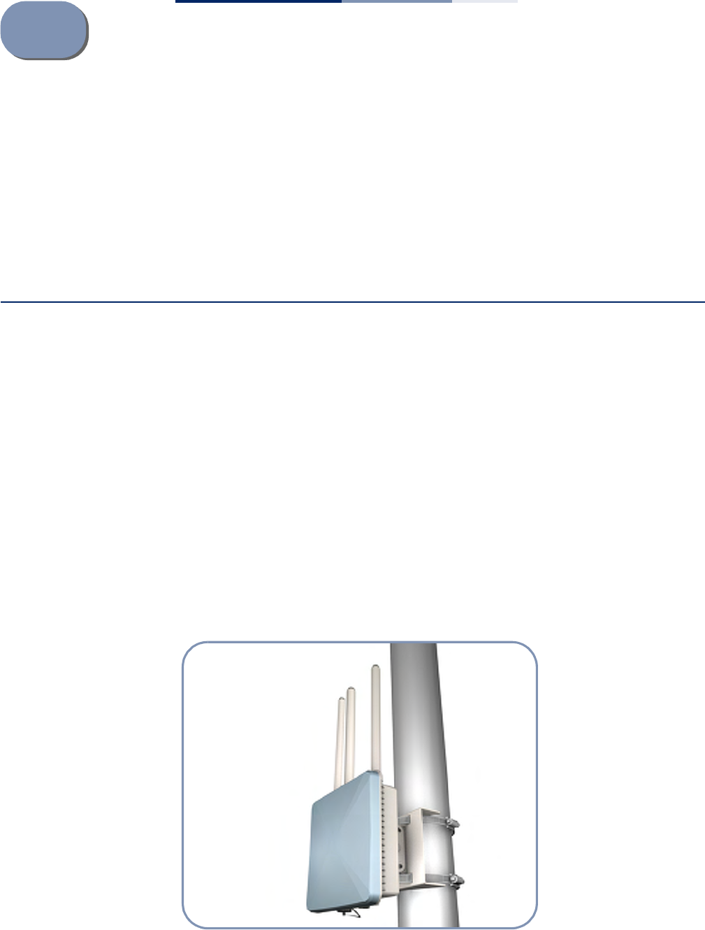
The SMC2890W-AN/SMC2891W-AN outdoor access point (AP) is built with leading-
edge technology to deliver reliable high-performance connectivity for your data
network.
The SMC2890W-AN/SMC2891W-AN is a dual-band IEEE 802.a/b/g/n AP that is
designed to deliver high-performance wireless services for clients or to provide
bridge links between remote LANs. Housed in a weatherproof enclosure for
mounting outdoors, the unit includes its own bracket for attaching to a pole, radio
mast, or tower structure. The unit is powered through its Ethernet cable connection
from a power injector module that is installed indoors.
In addition, the AP offers full network management capabilities through an easy-
to-use web interface, a command-line interface, and support for Simple Network
Management Protocol (SNMP) tools.
Figure 1: SMC2891W-AN Outdoor Access Point
Chapter 1
| Access Point Overview
Hardware Description
– 12 –
Key Hardware
Components
The SMC2890W-AN/SMC2891W-AN consists of serveral key harware components.
This manual describes each specific component, or related components, together
with their installation requirements and procedures in each chapter. To understand
each component in detail, refer to the relevant section.
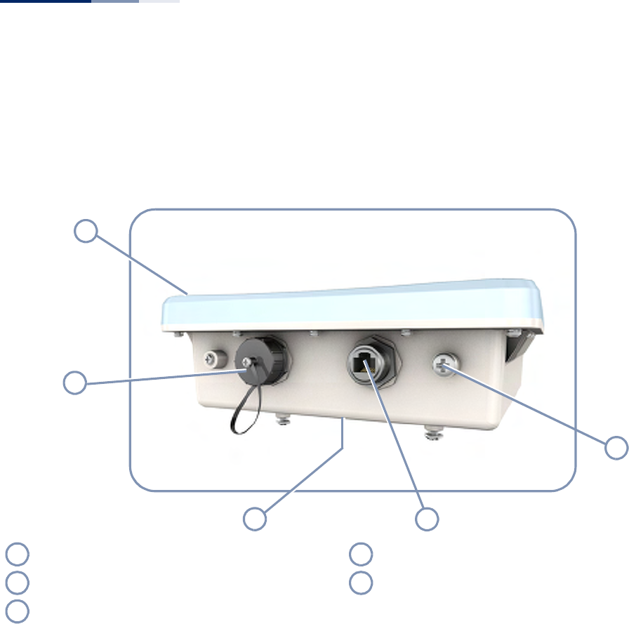
Figure 2: Bottom Panel View
Built-in 5 GHz Antenna
The SMC2891W-AN AP includes an integrated 5 GHz antenna. For more
information, see “How to Align Antennas” on page 28.
Console Port
The port labeled “Console” provides an out-of-band serial connection to a terminal
or a PC running terminal emulation software. The port can be used for performing
unit monitoring and configuration. For more information, see “How to Connect to
the Console Port” on page 45.
RJ-45 PoE Port
The RJ-45 port labeled “PoE” provides a 1000BASE-T data and Power-over-Ethernet
(PoE) power connection to the unit. For more information, see “How to Connect to
the RJ-45 Port” on page 37.
1
2
4
5
3
Built-in 5 GHz Antenna (SMC2891W-AN only) RJ-45 PoE Port
Console Port with Waterproof Cover Water-Tight Test Point (DO NOT REMOVE)
Back Panel System LEDs (Not Visible in Figure)
1
4
2
5
3
Chapter 1
| Access Point Overview
Hardware Description
– 13 –
System LEDs
For information on system status LED indicators, see “Understanding the System
Status LEDs” on page 44.
Water-Tight Test Point
Caution:
Do not remove or loosen this screw. Doing so could lead to damage of
the unit.
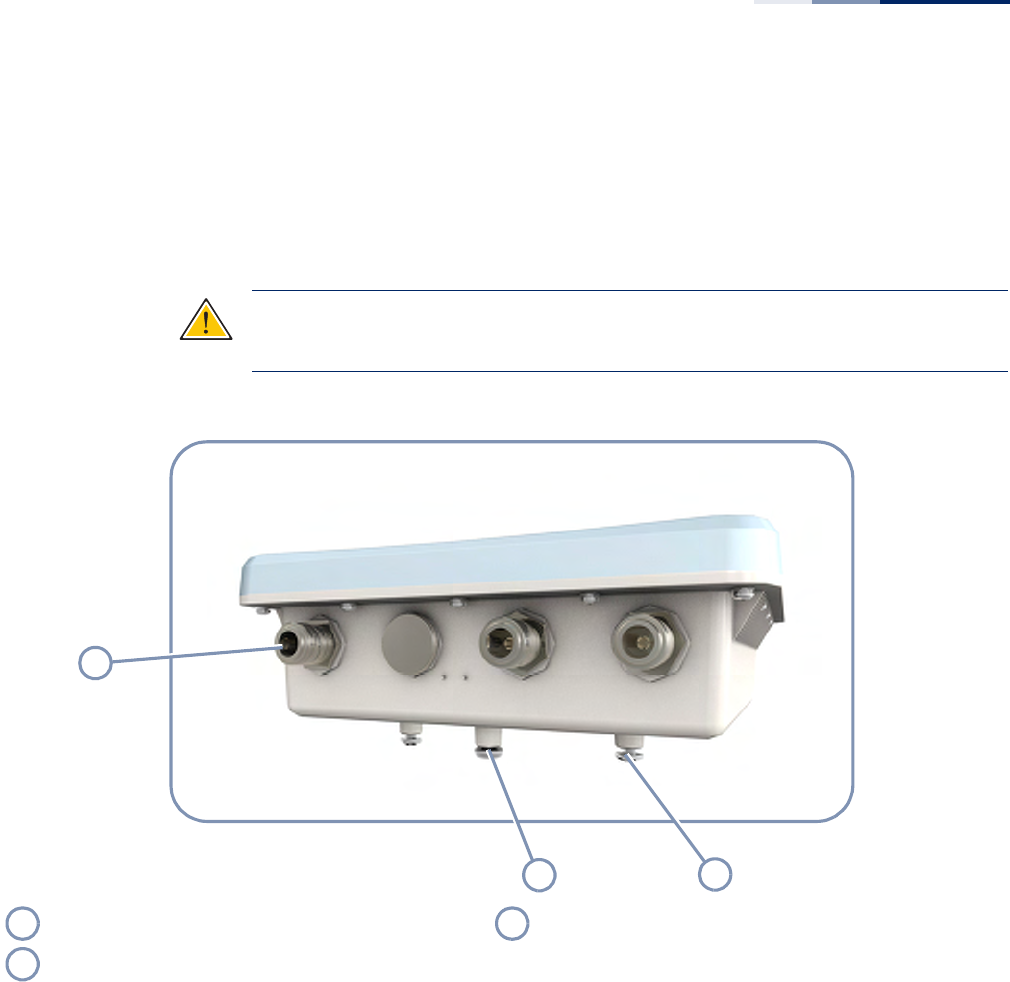
Figure 3: Top Panel View (SMC2891W-AN)
External Antenna Connectors
The SMC2890W-AN AP unit includes four external antenna connectors, two are for
the 2.4 GHz radio and two for the 5 GHz radio. The SMC2891W-AN AP unit includes
three external antenna connectors, two are for the 2.4 GHz radio and one for the
5 GHz radio (the unit also includes a built-in 5 GHz antenna). For more information,
see “How to Connect External Antennas” on page 27.
Ground Point
There is a ground point for grounding the AP chassis to earth. For more
information, see “How to Ground the Unit” on page 31.
1
23
External Antenna Connectors Pole/Wall Bracket Attachment Point
Ground Point
1
3
2
Chapter 1
| Access Point Overview
Hardware Description
– 14 –
Pole Mounting Bracket
The included Mounting Bracket Kit can be used to mount the unit on a 1.5 to 6 inch
diameter pole, or to part of a radio mast or tower structure. For more information,
see “How to Mount the Unit” on page 25.
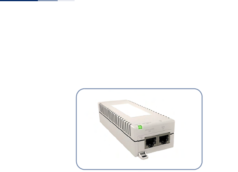
Figure 4: Power Injector Module
Power Injector Module
The AP receives power through a PoE connection to its RJ-45 port. The PoE power is
supplied from a power injector module that is installed indoors. For information,
see “Power Injector Module” on page 29.

Chapter 1
| Access Point Overview
Key Technical Specifications
– 15 –
Key Technical Specifications
The following table contains key system specifications for the AP.
Table 1: Key Technical Specifications
Item Specification
Ports One 10/100/1000 Mbps RJ-45 port
Network Interface RJ-45 Port: 1000BASE-T, PoE (PD) with waterproof cover
Console Port RS-232, RJ-45 waterproof connector
2.4GHz Radio IEEE 802.11b/g/n
5 GHz Radio IEEE 802.11a/n
External Antennas 4 N-Type female connecters (50 Ohms), 2x2 MIMO for 2.4 and 5 GHz
Integrated Antenna
(SMC2891W-AN only) 12 dBi @ 5 GHz, panel type, horizontal polarization
Radio Frequencies 2400 ~ 2483.5 MHz
2412 ~ 2472 MHz
5745 ~ 5825 MHz (China)
5180 ~ 5320 MHz (ETSI)
5500 ~ 5700 MHz (ETSI)
LEDs Power/System, Ethernet, 2.4GHz, 5GHz
PoE Input Power 38~57 VDC
Power Consumption 25.5 W maximum for IEEE 802.3at
12.95 W maximum for IEEE 802.3af
Weight 1.7 kg (3.75 lbs), unit without bracket or external antennas
Size W x D x H: 195 x 190 x 74 mm (7.68 x 7.48 x 2.91 inches)
Temperature Operating: -10 °C to 60 °C (-14 °F to 140 °F)
Storage: -20 °C to 70 °C (-4 °F to 158 °F)
Humidity Operating: 10% to 95% (non-condensing)
Wind Velocity Operational: 100 MPH (Miles per hour) / 44 mps
Survival: 150 MPH / 66 mps

– 16 –
2Installation Overview
This chapter includes these sections:
◆“Package Contents” on page 16
◆“System Configuration” on page 17
◆“AP Installation Tasks” on page 18
Package Contents
After unpacking the AP, check the contents to be sure you have received all the
components.
◆SMC2890W-AN or SMC2891W-AN Outdoor Access Point
◆Bracket Mounting Kit for pole mounting
◆PoE Power Injector with power cord—either US, Continental Europe or UK
◆Waterproof RJ-45 port cover
◆Console cable (RJ-45 to DB-9)
◆Quick Start Guide
◆Regulatory and Safety Information
◆Documentation CD — includes Installation Guide and Management Guide
Note that the following items are available options for the AP:
◆(Optional) Two external 2.4 GHz antennas
◆(Optional) One external 5 GHz antenna
◆(Optional) One mounting kit for 5 GHz external antenna
◆(Optional) 1.5 m low-loss 200 RF cable for 5 GHz external antenna
Chapter 2
| Installation Overview
System Configuration
– 17 –
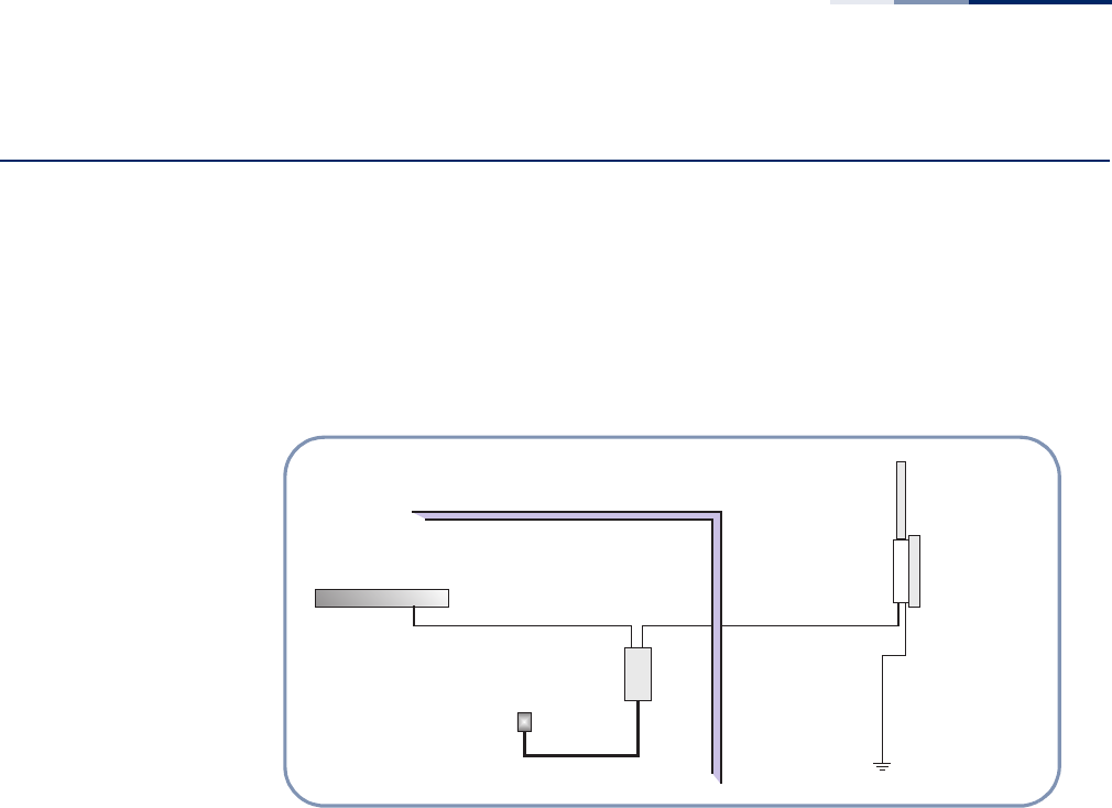
System Configuration
At each location where a unit is installed it must be connected to the local network,
either by using the power injector module, or by a direct connection to an
IEEE 802.3at-compliant LAN switch.
The following figure illustrates the system component connections.
Figure 5: System Configuration
Indoor Outdoor
LAN Switch
AC Power
Power
Injector
AP Unit
Ground Wire
Ethernet Cable Ethernet
Cable
External Antenna
Chapter 2
| Installation Overview
AP Installation Tasks
– 18 –
AP Installation Tasks
Follow these tasks to install the AP in your network. For full details on each task, go
to the relevant chapter or section by clicking on the link.
Unpack package and check contents
Unpack your AP and check the package contents to be sure you have received all
the items.
Before installing your AP, be sure to review all the safety statements and guidelines
in the Regulatory and Safety Information document.
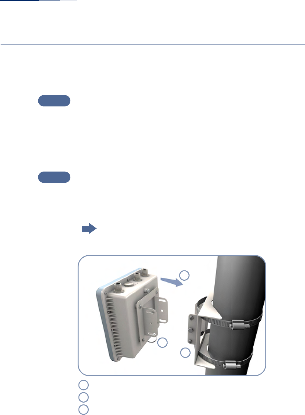
Mount the AP
After planning your installation, mount the unit on a pole, mast, or tower using the
mounting bracket. Also install the external antennas required for your wireless
service.
Go to the chapter “AP Chassis”
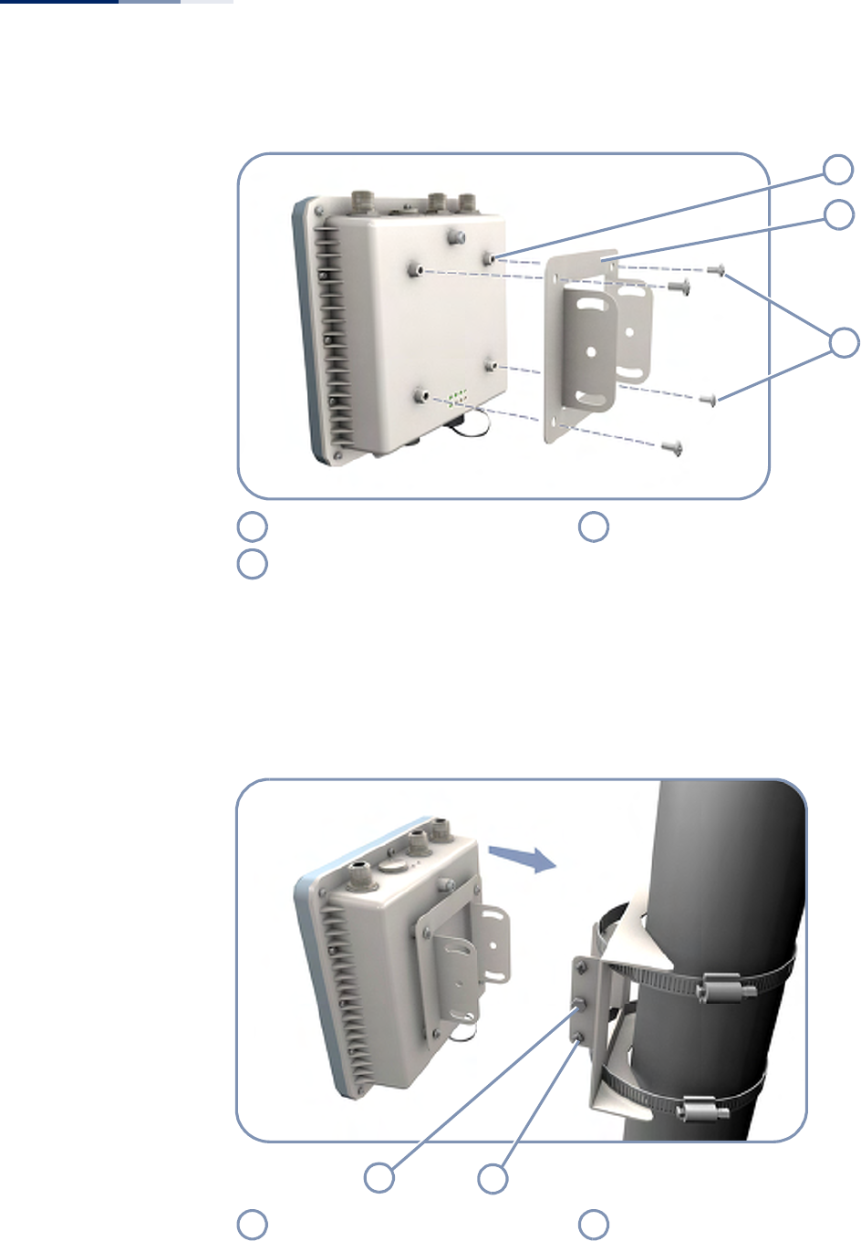
Figure 6: Installing the AP on a Pole
Task 1
Task 2
Attach one part of the bracket to the AP.
Attach the other parts of the bracket to the pole.
Link the two bracket parts together to secure the AP to the pole.
1
2
3
1
2
3
Chapter 2
| Installation Overview
AP Installation Tasks
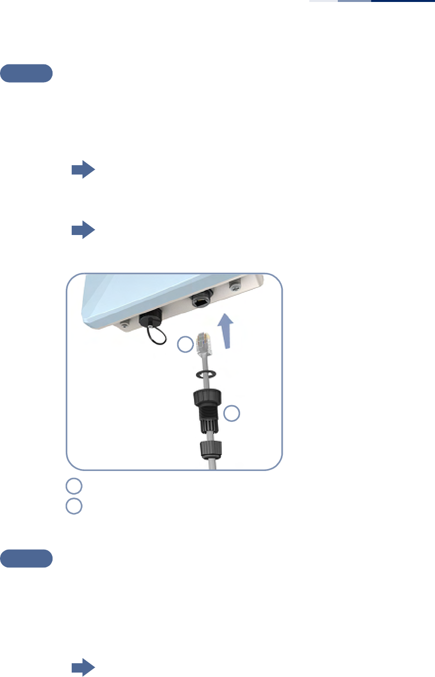
– 19 –
Connect Cables
Connect an Ethernet cable and a grounding wire to the unit.
Use outdoor-rated straight-through Ethernet cable to connect to the RJ-45 port for
your network connection.
Go to the chapter “Network Connections”
For details on connecting a ground wire:
Go to the section “How to Ground the Unit”
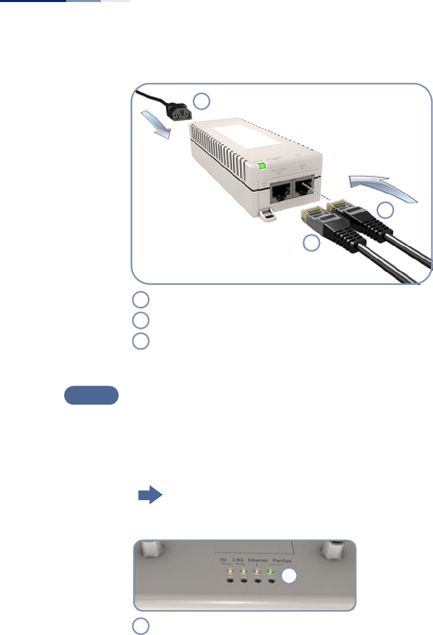
Figure 7: Making a Connection to the RJ-45 Port
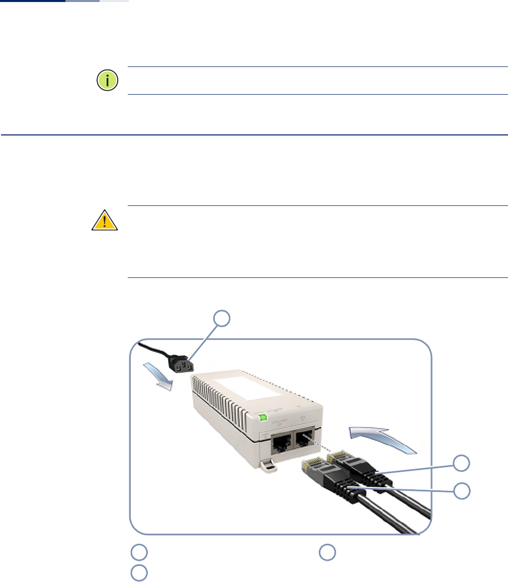
Install the PoE Power Injector and Power On
Install the PoE power injector indoors. Connect the power injector to the Ethernet
cable, a local LAN switch, and an AC power source.
Note that the AP can also be powered by connecting directly to a IEEE 802.3at PoE
switch.
Go to the chapter “Power and Grounding”
Task 3
Connect outdoor-rated Category 5e or better cable to the RJ-45 port.
Be sure to use the waterproof cover on the port.
1
2
1
2
Task 4
Chapter 2
| Installation Overview
AP Installation Tasks
– 20 –
Figure 8: Connecting AC Power
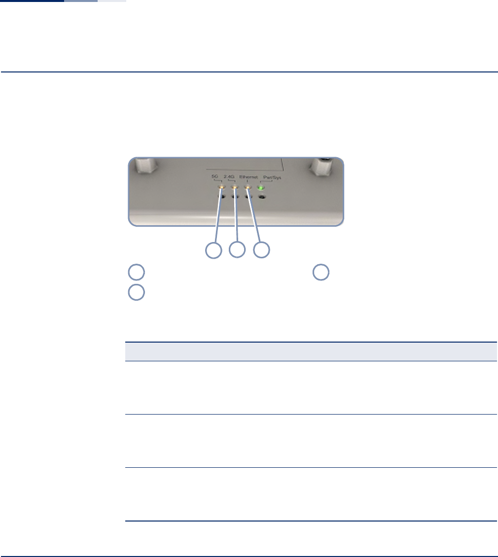
Verify AP Operation
Verify basic AP operation by checking the system LEDs.
When operating normally the Pwr/Sys LED should be on green, the Ethernet LED
on/blinking orange, and the wireless interface LEDs on/blinking orange.
Go to the section “Understanding the System Status LEDs”
Figure 9: System LEDs
Connect the AC power cord to a nearby AC power source.
Connect Ethernet cable from the “DATA IN” port to a LAN switch.
Connect straight-through Ethernet cable from the AP to the “DATA & POWER OUT” port.
1
2
3
1
2
3
Task 5
System Status LEDs.
1
1
Chapter 2
| Installation Overview
AP Installation Tasks
– 21 –
Make Initial Configuration Changes
At this point you may need to make a few basic configuration changes to the AP so
that it is compatible with your network. It is suggested to connect to the AP console
port to perform this task.
Go to “How to Connect to the Console Port”
Figure 10: Console Port
For information on AP configuration:
Refer to the Management Guide.
Task 6
Console Port.
1
1

Chapter 2
| Installation Overview
AP Installation Tasks
– 22 –
– 23 –
3AP Chassis
The AP includes its own bracket kit for mounting the unit to a 1.5 to 6 inch diameter
pole or part of a radio mast or tower structure.
Before continuing with AP installation, first review the general guidelines and
requirements in this chapter.
This chapter includes these sections:
◆“General Installation Guidelines” on page 23
◆“How to Mount the Unit” on page 25
◆“How to Connect External Antennas” on page 27
◆“How to Align Antennas” on page 28
General Installation Guidelines
Be sure to follow the guidelines below when choosing a location.
Caution:
The planning and installation of the AP requires professional personnel
that are trained in the installation of radio transmitting equipment. The user is
responsible for compliance with local regulations concerning items such as
antenna power, use of lightning arrestors, grounding, and radio mast or tower
construction. Therefore, it is recommended to consult a professional contractor
knowledgeable in local radio regulations prior to equipment installation.
Antenna Position When planning a location for the AP, consider these guidelines:
◆When installing for an access point service, be sure to place the unit and
external antennas in a location that can cover the intended service area.
◆Be sure there are no other radio antennas within 2 m (6 ft) of the AP.
◆Place the AP away from power and telephone lines.
◆Avoid placing the AP too close to any metallic surfaces, such as roof-installed
air-conditioning equipment, tinted windows, wire fences, or water pipes.

Chapter 3
| AP Chassis
General Installation Guidelines
– 24 –
Ethernet Cabling From the intended AP location, plan a cable route from the unit outdoors to the
power injector module indoors. Consider these guidelines:
◆The total Ethernet cable length should never be longer than 100 m (328 ft).
◆Determine a building entry point for the cable.
◆Determine if conduits, bracing, or other structures are required for safety or
protection of the cable.
◆For lightning protection at the power injector end of the cable, consider using a
lightning arrestor immediately before the cable enters the building.
Radio Interference The avoidance of radio interference is an important part of wireless network
planning. Interference is caused by other radio transmissions using the same or an
adjacent channel frequency. You should first scan your proposed site using a
spectrum analyzer to determine if there are any strong radio signals using the
802.11a/b/g/n channel frequencies. Always use a channel frequency that is furthest
away from another signal.
Weather Conditions When planning outdoor networks, you must take into account any extreme
weather conditions that are known to affect your location. Consider these factors:
◆Temperature — The AP is tested for normal operation in temperatures from
-10° C to 60° C. Operating in temperatures outside of this range may cause the
unit to fail.
◆Wind Velocity — The AP can operate in winds up to 44 m/s and survive higher
wind speeds up to 66 m/s. You must consider the known maximum wind
velocity and direction at the site and be sure that any supporting structure,
such as a pole, mast, or tower, is built to withstand this force.
◆Lightning — The AP includes its own built-in lightning protection. However,
you should make sure that the unit, any supporting structure, and cables are all
properly grounded. Additional protection using lightning rods, lightning
arrestors, or surge suppressors may also be employed.
◆Rain — The AP is weatherproofed against rain. Also, prolonged heavy rain has
no significant effect on the radio signal. However, it is recommended to apply
weatherproof sealing tape around all connectors for extra protection.
◆Snow and Ice — Falling snow, like rain, has no significant effect on the radio
signal. However, a build up of snow or ice on antennas may cause links to fail. In
this case, the snow or ice has to be cleared from the antennas to restore
operation of the unit.
Chapter 3
| AP Chassis
How to Mount the Unit
– 25 –
How to Mount the Unit
The AP can be mounted in the following ways using the included mounting
bracket:
◆To a 1.5 to 6 inch diameter pole
The AP’s mounting bracket has two main parts. One part that can be secured to a
pole using two steel-band clamps, and another part that attaches directly to the AP.
The two parts link together and allow the tilt angle of the unit to be adjusted for
antenna alignment.
How to Pole Mount Perform the following steps to mount the unit to a 1.5 to 6 inch diameter pole or
tube using the mounting bracket:
1. Using the two included steel-band clamps, thread them through the slats
provided in the pole-mount part of the bracket.
2. Place the pole-mount part of the bracket against the pole and tighten the steel-
band clamps until it is secure.
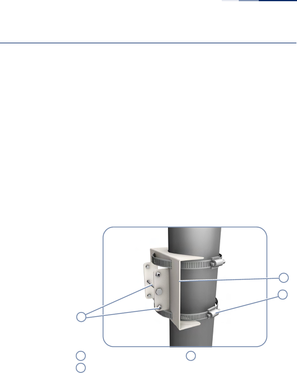
Figure 11: Attach Bracket to Pole
3. Attach the square mounting plate to the AP with the supplied screws.
Pole Mount Bracket Part Securing Screws, Nut and Bolt
Steel-Band Clamps
2
1
3
1
3
2
Chapter 3
| AP Chassis
How to Mount the Unit
– 26 –
Figure 12: Attach Bracket to AP
4. Attach the AP with its mounting plate to the bracket already fixed to the pole.
5. Use the included long bolt to secure the AP to the pole bracket. Note that the
AP tilt angle may need to be adjusted for antenna alignment.
Figure 13: Mount the AP on the Pole
Bracket Mount Points Supplied Bracket Mount Screws
Square Mounting Bracket Part
Long Steel Bolt Tilt Angle Securing Screws (Four)
1
2
3
1
3
2
12
1
2
Chapter 3
| AP Chassis
How to Connect External Antennas
– 27 –
6. Secure the AP at the required tilt angle using the two screws provided in the
mounting kit.
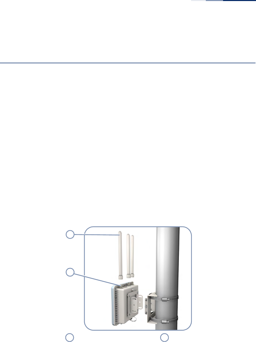
How to Connect External Antennas
When deploying an AP, you need to mount external antennas and connect them to
the unit. Two antennas are required for 2.4 GHz operation and two can be used for
5 GHz operation. These antennas are not included in the AP package.
The SMC2891W-AN unit includes an integrated high-gain antenna for 5 GHz
operation. External antennas are not required for 5 GHz operation only for 2.4 GHz
operation.
Some omnidirectional external antennas attach directly to the N-type connectors
on the unit. Other antennas may include their own mounting brackets and connect
to the unit using RF coaxial cables.
Perform these steps:
1. For external antennas with mounting brackets, mount the antennas to the
same supporting structure as the AP, within 3 m (10 ft) distance, using the
brackets supplied in the antenna package.
2. Connect the antennas either directly to the AP’s N-type connectors, or use RF
coaxial cable provided in the antenna package.
Figure 14: Connect External Antennas
Direct-Attach Omnidirectional External
Antennas N-Type External Antenna Connectors
1
2
1
2

Chapter 3
| AP Chassis
How to Align Antennas
– 28 –
3. Apply weatherproofing tape to the antenna connectors to help prevent water
entering the connectors.
Note
:
Be sure to take account of the antenna polarization direction; all antennas in
a link must be mounted with the same polarization.
How to Align Antennas
When using the SMC2891W-AN unit with its 5 GHz integrated high-gain antenna,
you will need to accurately align the antenna with another unit in the network to
ensure optimum performance. Proper antenna alignment is particularly important
for long-range point-to-point links.
◆Point-to-Point Configurations — In a point-to-point configuration the
alignment process requires two people at each end of the link. The use of cell
phones or two-way radio communication may help with coordination. To start,
you can just point the antennas at each other, using binoculars or a compass to
set the general direction. Then you can adjust the horizontal and vertical
position to find the position where the signal is strongest and secure the unit in
that position.
◆Point-to-Multipoint Configurations — In a point-to-multipoint configuration
all SMC2891W-AN units must be aligned with a central SMC2890W-AN unit that
may be using external omnidirectional or sector antennas. The alignment
process is the same as in point-to-point links, but only the SMC2891W-AN units
require the adjustment for proper alignment.
To start, you can just point the SMC2891W-AN antenna at the central
SMC2890W-AN unit, using binoculars or a compass to set the general direction.
Then you can adjust the horizontal and vertical position to find the position
where the signal is strongest and secure the unit in that position.
Note
:
The receive signal strength of the radio signal on the local and remote unit
can be viewed using the CLI or web management interfces. Refer the Management
Guide for further information.
– 29 –
4Power and Grounding
This chapter focuses on how to power-on the AP. The AP can be powered using the
included PoE Power Injector or by a direct connection to a PoE LAN switch.
Connecting the AP to ground is also covered.
This chapter includes these sections:
◆“Power Injector Module” on page 29
◆“How to Ground the Unit” on page 31
◆“How to Install the Power Injector” on page 32
Power Injector Module
The AP receives power through its network cable connection using power-over-
Ethernet technology. A power injector module is included in the AP package and
provides two RJ-45 Ethernet ports, one for connecting to the AP (DATA & POWER
OUT), and the other for connecting to a local LAN switch (DATA IN).
The DATA IN port uses an MDI (that is, internal straight-through) pin configuration.
You can therefore use straight-through twisted-pair cable to connect this port to
most network interconnection devices such as a switch or router that provide MDI-
X ports. However, when connecting the access point to a workstation or other
device that does not have MDI-X ports, you must use crossover twisted-pair cable.
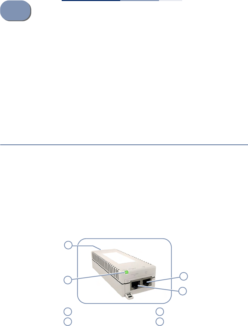
Figure 15: PoE Power Injector
Ethernet from Local Network LED Indicator
Ethernet and Power to AP AC Power Socket (Hidden)
4
31
2
1
3
2
4

Chapter 4
| Power and Grounding
Power Injector Module
– 30 –
The AP does not have a power switch. It is powered on when its Ethernet port is
connected to the power injector module, and the power injector module is
connected to an AC power source.
The power injector includes one LED indicator that turns on when AC power is
applied.
The power injector module automatically adjusts to any AC voltage between 100-
240 volts at 50 or 60 Hz. No voltage range settings are required.
Caution:
The power injector module is designed for indoor use only. Never mount
the power injector outside with the AP unit.
Table 2: Power Injector Module Specifications
Item Description
AC Input 100~240 VAC, 50/60 Hz, 0.5 A
DC Output 48 VDC, 0.35 A
Output Power 16.8 W maximum
DATA IN Port 10/100/1000BASE-T, RJ-45 socket
DATA & POWER OUT Port 10/100/1000BASE-T, RJ-45 socket
50 VDC on wire pairs 4, 5 (+) and 7, 8 (-)
Temperature Operating: 0 - 40 °C (32 - 104 °F)
Storage: -20 - 70 °C (-4 - 158 °F)
Humidity Operating: 10 - 90% non-condensing
Storage: 10 - 90% non-condensing
Size W x L x H: 50 x 140 x 35 mm (4.2 x 9.0 x 1.6 inches)
Table 3: Power Injector Module Status LED
LED Status Indication
On Yellow Module is receiving power.
On Green The module is connected to the AP and supplying power.
Blinking Green Module has detected an overload state or short-circuit condition.
Chapter 4
| Power and Grounding
How to Ground the Unit
– 31 –
How to Ground the Unit
When connecting a ground wire to the AP, use the grounding screw on the unit. Be
sure to use #14 AWG or larger copper core ground wire.
Caution
:
Be sure that grounding is available and that it meets local and national
electrical codes. Grounding the AP must be performed by a professional installer.
The ground wire can be connected to a point on the bracket, pole, metal grounding
plate, or directly to an earth termination. Make sure that there is a good electrical
connection between the ground wire and the grounding point (no paint or
isolating surface treatment).
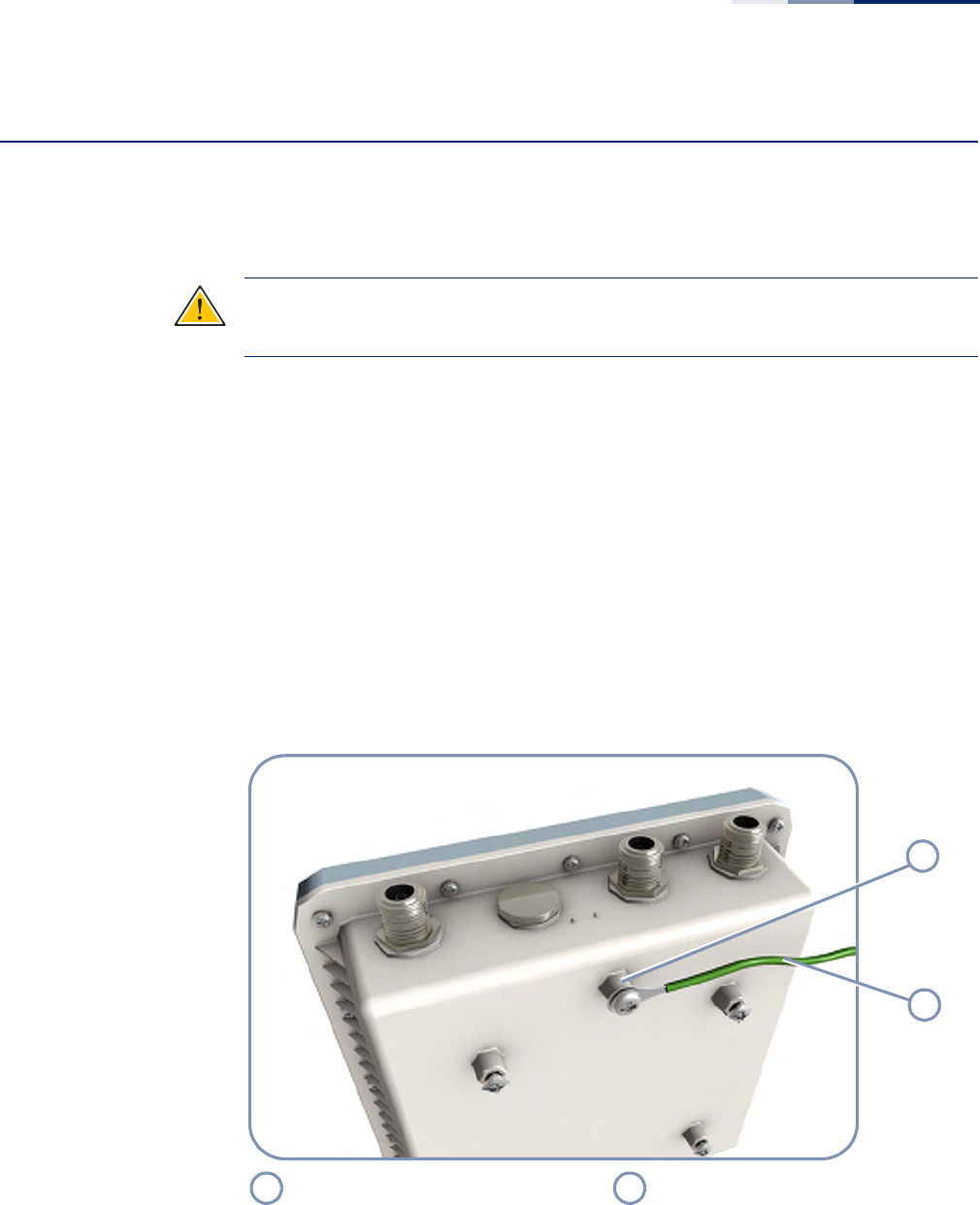
To connect a grounding wire to the AP, follow these steps:
1. Crimp a ring lug onto the end of the ground wire before connecting it to the
unit.
2. Place the ground wire lug on one of the grounding points and firmly tighten
the screw.
Figure 16: Ground Wire Connection
3. Connect the other end of the grounding wire to a good ground (earth)
connection.
AP Ground Point Grounding Wire
1
2
1
2
Chapter 4
| Power and Grounding
How to Install the Power Injector
– 32 –
Note
:
Use cable strips to secure all cables to the pole.
How to Install the Power Injector
The power injector can be installed indoors on any horizontal surface, such as a
desktop or shelf, or on a wall.
Caution
:
Do not install the power injector outdoors. The unit is for indoor
installation only.
Caution
:
Install lightning protection at the power injector end of the Ethernet
cable, use a lightning arrestor immediately before the cable enters the building.
Figure 17: Connecting the Power Injector
1. Connect outdoor-rated Ethernet cable from the AP to the RJ-45 port labeled
“DATA & POWER OUT” on the power injector.
2. Connect a straight-through unshielded twisted-pair (UTP) cable from a local
LAN switch to the RJ-45 port labeled “DATA IN” on the power injector. Use
Category 5e or better UTP cable for 10/100/1000BASE-T connections.
AC Power Cord DATA & POWER OUT Port
DATA IN Port
1
2
3
1
3
2

Chapter 4
| Power and Grounding
How to Install the Power Injector
– 33 –
3. Insert the power cable plug into the standard AC socket on the power injector
and the other end into a grounded, 3-pin socket, AC power source.
Note:
For International use, you may need to change the AC line cord. You must
use a line cord set that has been approved for the socket type in your country.
4. Check the LED on top of the power injector to be sure that power is being
supplied to the power injector.

Chapter 4
| Power and Grounding
How to Install the Power Injector
– 34 –

– 35 –
5Network Connections
This chapter focuses on making connections to the AP’s network interfaces and
details on network cable specifications.
The AP features one 1000BASE-T RJ-45 port as well as wireless interfaces. The
sections that follow describe the network interfaces.
This chapter includes these sections:
◆“Understanding the Network Status LEDs” on page 36
◆“How to Connect to Radio Interfaces” on page 36
◆“How to Connect to the RJ-45 Port” on page 37
Chapter 5
| Network Connections
Understanding the Network Status LEDs
– 36 –
Understanding the Network Status LEDs
The AP includes LED indicators to indicate network link status and activity. The
LEDs are shown below and are described in the following table.
Figure 18: Network Status LEDs
How to Connect to Radio Interfaces
The 802.11a standard operates in the 5 GHz Unlicensed National Information
Infrastructure (UNII) band, and the 802.11b/g standard in the 2.4 GHz band. The
802.11n standard operates in both the 2.4 GHz and 5 GHz bands.
Once the AP is installed and powered on, wireless clients can connect to the
802.11b/g/n radio interface using the 2.4 GHz band, or to the 802.11a/n radio using
the 5 GHz band. The radio and authentication settings for wireless clients can be
configured through management interfaces. For more information, refer to the
Management Guide.
5 GHz Link/Activity LED LAN Link/Activity LED
2.4 GHz Link/Activity LED
Figure 19: Network Status LEDs
LED Condition Status
Ethernet On Orange Port has a valid link.
Blinking Orange Indicates activity on the port.
Off The link is down.
2.4G On Orange The 802.11b/g/n 2.4 GHz radio is enabled.
Blinking Orange Indicates network activity.
Off The 2.4 GHz radio is disabled.
5G On Orange The 802.11a/n 5 GHz radio is enabled.
Blinking Orange Indicates network activity.
Off The 5 GHz radio is disabled.
123
1
3
2
Chapter 5
| Network Connections
How to Connect to the RJ-45 Port
– 37 –
How to Connect to the RJ-45 Port
The connection between the AP’s RJ-45 port and the PoE power injector requires
outdoor-rated Category 5E or better Ethernet cable with RJ-45 plugs on each end.
The length of the Ethernet cable should be less than 100 meters (328 ft).
Copper Cabling
Guidelines
Before connecting the Ethernet copper cable, first plan a cable route from the AP
outdoors to the PoE power injector indoors. Consider these guidelines:
◆Make sure the cable distance does not exceed 100 meters (328 ft).
◆Determine a building entry point for the cable.
◆Determine if conduits, bracing, or other structures are required for safety or
protection of the cable.
◆Be sure to ground the outdoor-rated Ethernet cable immediately before it
enters the building. See “Grounding the Ethernet Cable” on page 41.
◆For additional lightning protection, it is recommended to use a lightning
arrestor immediately before the Ethernet cable enters the building.
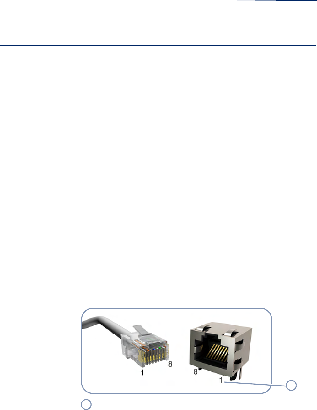
10/100BASE-TX Pin
Assignments
Most 100BASE-TX RJ-45 ports support automatic MDI/MDI-X operation, so you can
use straight-through or crossover cables for all network connections to PCs,
switches, or hubs. In straight-through cable, pins 1, 2, 3, and 6, at one end of the
cable, are connected straight through to pins 1, 2, 3, and 6 at the other end of the
cable.
Figure 20: RJ-45 Connector
RJ-45 Pin Numbers
1
1

Chapter 5
| Network Connections
How to Connect to the RJ-45 Port
– 38 –
1000BASE-T Pin
Assignments
All 1000BASE-T ports support automatic MDI/MDI-X operation, so you can use
straight-through cables for all network connections to PCs or servers, switches or
hubs.
The table below shows the 1000BASE-T MDI and MDI-X port pinouts. These ports
require that all four pairs of wires be connected. Note that for 1000BASE-T
operation, all four pairs of wires are used for both transmit and receive.
Table 4: 10/100BASE-TX MDI and MDI-X Port Pinouts
Pin MDI Signal Namea
a. The “+” and “-” signs represent the polarity of the wires that make up each wire pair.
MDI-X Signal Name
1 Transmit Data plus (TD+)
-52V power (Negative Vport)Receive Data plus (RD+)
GND (Positive Vport)
2 Transmit Data minus (TD-)
-52V power (Negative Vport)Receive Data minus (RD-)
GND (Positive Vport)
3 Receive Data plus (RD+)
GND (Positive Vport)Transmit Data plus (TD+)
-52V power (Negative Vport)
4 -52V power (Negative Vport) GND (Positive Vport)
5 -52V power (Negative Vport) GND (Positive Vport)
6Receive Data minus (RD-)
GND (Positive Vport)Transmit Data minus (TD-)
-52V power (Negative Vport)
7 GND (Positive Vport)-52V power (Negative V
port)
8 GND (Positive Vport)-52V power (Negative V
port)

Chapter 5
| Network Connections
How to Connect to the RJ-45 Port
– 39 –
1000BASE-T Cable Requirements
All Category 5 UTP cables that are used for 100BASE-TX connections should also
work for 1000BASE-T, providing that all four wire pairs are connected. However, it is
recommended that for all critical connections, or any new cable installations,
Category 5e (enhanced Category 5) or Category 6 cable should be used. The
Category 5e and 6 specifications include test parameters that are only
recommendations for Category 5. Therefore, the first step in preparing existing
Category 5 cabling for running 1000BASE-T is a simple test of the cable installation
to be sure that it complies with the IEEE 802.3-2008 standards.
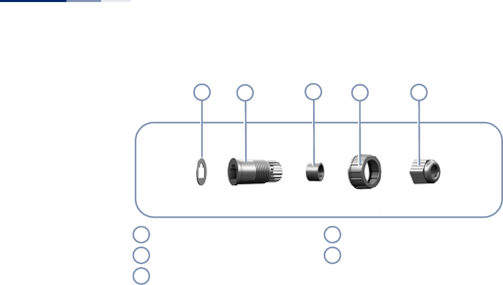
Connection Procedure Follow these steps to connect Ethernet copper cable to the AP’s RJ-45 twisted-pair
copper port:
Note
:
Connecting the Ethernet cable to the AP powers on the unit.
1. Disassemble the waterproof port cover into its five parts:; the outer screw-on
cover, the screw-on cable clamp, the inner plastic RJ-45 plug cover, the inner
rubber cable seal, and the rubber port seal.
Table 5: 1000BASE-T MDI and MDI-X Port Pinouts
Pin MDI Signal Name MDI-X Signal Name
1 Bi-directional Pair A Plus (BI_DA+)
-52V power (Negative Vport)Bi-directional Pair B Plus (BI_DB+)
GND (Positive Vport)
2 Bi-directional Pair A Minus (BI_DA-)
-52V power (Negative Vport)Bi-directional Pair B Minus (BI_DB-)
GND (Positive Vport)
3 Bi-directional Pair B Plus (BI_DB+)
GND (Positive Vport)Bi-directional Pair A Plus (BI_DA+)
-52V power (Negative Vport)
4 Bi-directional Pair C Plus (BI_DC+)
-52V power (Negative Vport)Bi-directional Pair D Plus (BI_DD+)
GND (Positive Vport)
5 Bi-directional Pair C Minus (BI_DC-)
-52V power (Negative Vport)Bi-directional Pair D Minus (BI_DD-)
GND (Positive Vport)
6 Bi-directional Pair B Minus (BI_DB-)
GND (Positive Vport)Bi-directional Pair A Minus (BI_DA-)
-52V power (Negative Vport)
7 Bi-directional Pair D Plus (BI_DD+)
GND (Positive Vport)Bi-directional Pair C Plus (BI_DC+)
-52V power (Negative Vport)
8 Bi-directional Pair D Minus (BI_DD-)
GND (Positive Vport)Bi-directional Pair C Minus (BI_DC-)
-52V power (Negative Vport)
Chapter 5
| Network Connections
How to Connect to the RJ-45 Port
– 40 –
Figure 21: Waterproof RJ-45 Port Cover
2. Peal-off the adhesive backing on the rubber RJ-45 port seal and stick it on the
end of the plastic RJ-45 plug cover.
3. Cut the Ethernet cable to the required length, and then feed the cable end
through the RJ-45 port waterproof cover parts in this order:
■Screw-on cable clamp
■Outer screw-on cover
■Inner rubber cable seal
■Inner plastic RJ-45 plug cover (with rubber seal attached)
4. Crimp a new RJ-45 connector (not supplied) on the end of the Ethernet cable.
5. Push the inner rubber cable seal into the clamp end of the plastic RJ-45 plug
cover.
6. Connect the RJ-45 plug to the AP’s RJ-45 port.
7. Push the inner plastic RJ-45 plug cover over the RJ-45 plug, and then secure it
to the AP using the outer screw-on cover. Tighten the outer screw-on cover to
ensure protection against moisture.
8. Screw the inner rubber cable seal onto the inner plastic RJ-45 plug cover.
Tighten the seal to ensure protection against moisture.
Rubber RJ-45 Port Seal Outer Screw-on Cover
Inner Plastic RJ-45 Plug Cover Screw-on Cable Clamp
Inner Rubber Cable Seal
12345
1
4
2
5
3
Chapter 5
| Network Connections
How to Connect to the RJ-45 Port
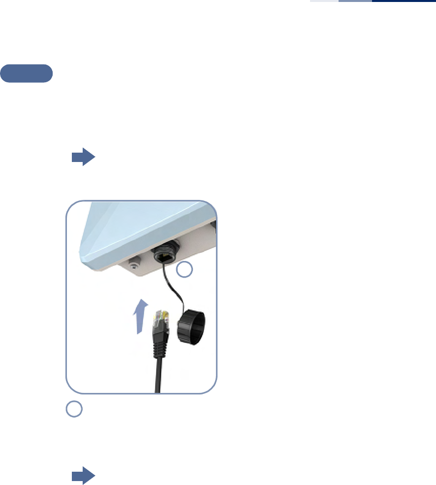
– 41 –
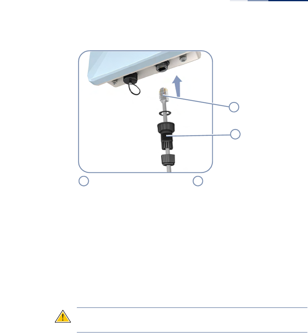
Figure 22: Making a Connection to the RJ-45 Port
9. Seal the PoE port connector using tar seal or weatherproof tape for extra
protection against rain and moisture.
10. Route the Ethernet cable from the AP to the power injector (or PoE LAN switch)
following your cable plan and connect it to the “DATA & POWER OUT” port. The
Power LED on the AP should turn on to indicate a valid link.
Grounding the
Ethernet Cable
To comply with safety regulations, the shield of the outdoor-rated Ethernet cable
must be connected to protective ground (earth). The grounding point can be either
inside the building, or immediately at the entry point to the building, depending
on where a protective ground is available.
Caution
:
Grounding the outdoor-rated Ethernet cable must be performed by a
professional installer in conformance with local safety regulations.
This document proposes one method for grounding the outdoor-rated Ethernet
cable through its drain wire. The actual connection method employed is left to the
professional installer.
To ground the outdoor-rated Ethernet cable, follow these steps:
1. Strip back about a one inch (2.4 cm) section of the Ethernet cable jacket to
expose the drain wire.
RJ-45 Plug on Ethernet Cable Waterproof RJ-45 Port Cover Assembly
1
2
1
2
Chapter 5
| Network Connections
How to Connect to the RJ-45 Port
– 42 –
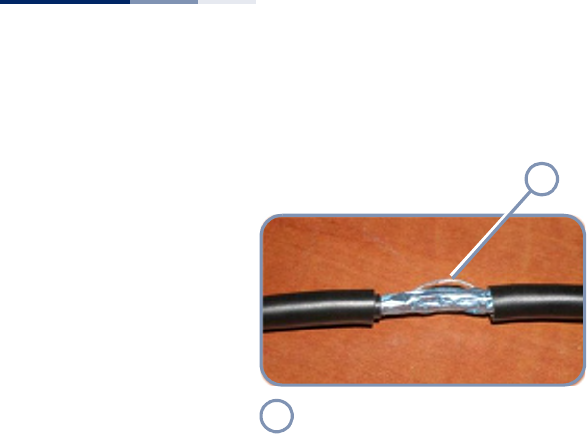
Figure 23: Outdoor-Rated Ethernet Cable Drain Wire
2. Attach a grounding cable to the drain wire and then connect it to protective
earth.
3. Use weatherproof tape to cover and seal the attachment area on the Ethernet
cable.
Drain Wire
1
1

– 43 –
6AP Management
The AP includes a management agent that allows you to configure or monitor the
AP using its embedded management software. To manage the AP, you can make a
direct connection to the console port (out-of-band), or you can manage it through
a network connection (in-band) using Telnet, Secure Shell (SSH), a web browser, or
SNMP-based network management software.
For a detailed description of the AP’s software features, refer to the Management
Guide.
This chapter includes these sections:
◆“Understanding the System Status LEDs” on page 44
◆“How to Connect to the Console Port” on page 45
Chapter 6
| AP Management
Understanding the System Status LEDs
– 44 –
Understanding the System Status LEDs
The AP includes LED indicators that indicate system and port status. The LEDs are
shown below and are described in the following table.
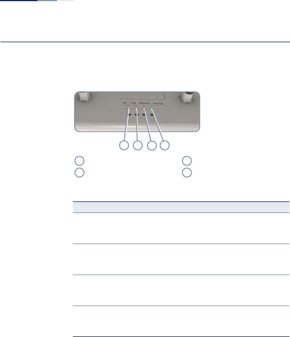
Figure 24: System Status LEDs
5 GHz Link/Activity LED LAN Link/Activity LED
2.4 GHz Link/Activity LED Power/System LED
Figure 25: System Status LEDs
LED Condition Status
Power On Green The system power is on.
Blinking Green The system is currently booting up.
Off System is off (no power).
LAN On Orange Port has a valid link.
Blinking Orange Indicates activity on the port.
Off The link is down.
2.4G On Orange The 802.11b/g/n 2.4 GHz radio is enabled.
Blinking Orange Indicates network activity.
Off The 2.4 GHz radio is disabled.
5G On Orange The 802.11a/n 5 GHz radio is enabled.
Blinking Orange Indicates network activity.
Off The 5 GHz radio is disabled.
1234
1
3
2
4

Chapter 6
| AP Management
How to Connect to the Console Port
– 45 –
How to Connect to the Console Port
The RJ-45 Console port on the AP is used to connect to the AP for out-of-band
console configuration. The console device can be a PC or workstation running a VT-
100 terminal emulator, or a VT-100 terminal. An RJ-45-to-DB-9 cable is supplied
with the AP for connecting to a PC’s RS-232 serial DB-9 DTE (COM) port.
Note:
To connect to notebooks or other PCs that do not have a DB-9 COM port, use
a USB to male DB-9 adapter cable (not included with the AP).
The following table describes the pin assignments used in the RJ-45-to-DB-9
console cable.
The serial port’s configuration requirements are as follows:
◆Default Baud rate—115,200 bps
◆Character Size—8 Characters
◆Parity—None
◆Stop bit—One
◆Data bits—8
◆Flow control—none
Table 6: Console Cable Wiring
AP’s 8-Pin
Console Port
Null Modem PC’s 9-Pin
DTE Port
1 RXD (receive data) <--------------------- 3 TXD (transmit data)
3 TXD (transmit data) ---------------------> 2 RXD (receive data)
4 SGND (signal ground) ----------------------- 5 SGND (signal ground)
No other pins are used.
Chapter 6
| AP Management
How to Connect to the Console Port
– 46 –
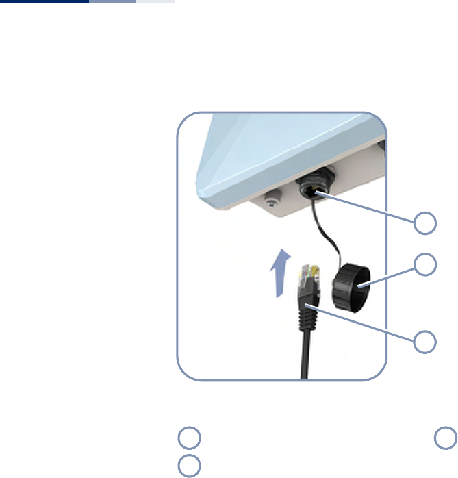
Figure 26: Console Port Connection
Follow these steps to connect to the Console port:
1. Unscrew the waterproof protective cap on the AP’s Console port.
2. Attach the DB-9 end of the included serial cable to a DB-9 COM port connector
on a management PC. Use a USB to male DB-9 adapter cable (not included) if
needed.
3. Attach the RJ-45 end of the serial cable to the Console port on the AP.
4. Configure the PC’s COM port required settings using VT-100 terminal emulator
software (such as HyperTerminal) running on the management PC.
5. Log in to the command-line interface (CLI) using default settings:
■User — admin
■Password — null (there is no default password)
6. When you have completed your console session, remove the console cable and
replace the waterproof cap on the connector.
For a detailed description of connecting to the console and using the AP’s
command line interface (CLI), refer to the Management Guide.
RJ-45 Console Port Console Cable
Waterproof Port Cover
1
2
3
1
3
2

– 47 –
ATroubleshooting
Diagnosing LED Indicators
System Self-Diagnostic Test Failure
If there is a failure of the system power-on-self-test (POST), you can use a console
connection to view the POST results. The POST results may indicate a failed
component or help troubleshoot the problem. For more information on
connecting to the console port and using the CLI, refer to the Management Guide.
Note a POST failure normally indicates a serious hardware fault that cannot be
rectified or worked around. If you encounter a POST failure, you should contact
your dealer for assistance.
Power Problems
If the power indicator does not turn on when the Ethernet cable is plugged in, you
may have a problem with the power outlet, power cord, or PoE power injector.
However, if the unit powers off after running for a while, check for loose power
connections, power losses or surges at the power outlet. If you still cannot isolate
the problem, the PoE power injector may be defective.
Table 7: Troubleshooting Chart
Symptom Action
Power LED is Off ◆Check connections between the PoE Power Injector, the power
cord and the wall outlet.
◆Contact your dealer for assistance.
LAN LED is Off ◆Verify that the AP and attached PoE Power Injector are powered
on.
◆Be sure the cable is plugged into both the AP and PoE Power
Injector.
◆Verify that the proper cable type is used and its length does not
exceed specified limits.
◆Check the cable connections for possible defects. Replace the
defective cable if necessary.

Chapter A
| Troubleshooting
Installation
– 48 –
Installation
Verify that all system components have been properly installed. If one or more
components appear to be malfunctioning (such as the power cord or network
cabling), test them in an alternate environment where you are sure that all the
other components are functioning properly.
Wireless Connection Problems
If wireless clients cannot access the network, check the following items before you
contact your local dealer for assistance:
◆Be sure the AP and wireless clients are configured with the same Service Set ID
(SSID).
◆Ensure that wireless clients are properly configured with the appropriate
authentication or encryption keys.
◆If authentication is being performed through a RADIUS server, ensure that the
clients are properly configured on the RADIUS server.
◆If authentication is being performed through IEEE 802.1X, be sure the wireless
users have installed and properly configured 802.1X client software.
In-Band Access
If the AP cannot be configured using Telnet, a web browser, or SNMP software:
◆Be sure to have configured the AP with a valid IP address, subnet mask and
default gateway.
◆Check that you have a valid network connection to the AP and that the
Ethernet port or the wireless interface that you are using has not been disabled.
◆If you are connecting to the AP through the wired Ethernet interface, check the
network cabling between the management station and the AP. If you are
connecting to the AP from a wireless client, ensure that you have a valid
connection to the AP.
◆If you cannot connect using Telnet, you may have exceeded the maximum
number of concurrent Telnet sessions permitted. Try connecting again at a later
time.

Chapter A
| Troubleshooting
Out-of-Band Access
– 49 –
Out-of-Band Access
If you cannot access the on-board configuration program via a serial port
connection:
◆Be sure you have set the terminal emulator program to VT100 compatible, 8
data bits, 1 stop bit, no parity and 115200 Baud Rate.
◆Check that the null-modem serial cable conforms to the pin-out connections
provided in “How to Connect to the Console Port” on page 45.
Reset the Access Point
If all other recovery measure fail, and the AP is still not functioning properly, take
any of these steps to reset the AP’s hardware:
◆Enter the “reload” command from the console interface.
◆Restart the AP from the web interface.
◆Perform a power reset.

– 50 –
Index
Numerics
10/100 pin assignments 37
1000BASE-T pin assignments 38
A
AC power connection 33
antenna position 23
antennas, external 13
B
basic installation tasks 18
baud rate, console 45
bracket kit 14
C
cable grounding 41
cabling guidelines 24
chassis grounding 12, 13
connection of system 17
console port 12
console port, pin assignments 45
contents of package 16
copper cable connection 37
cover, weatherproof 40
D
diagnosing LED indicators 47
diagnostic test failure 47
E
environmental specifications 15
equipment checklist 16
Ethernet RJ-45 port 12
external antennas 13
external antennas, mounting 27
G
ground points 12, 13
grounding Ethernet cable 41
grounding the AP 31
H
hardware errors 47
hardware overview 11
hardware specifications 15
humidity specifications 15
I
in-band access 48
indicators, LED 36, 44
injector module 14
installation tasks 18
installation troubleshooting 48
interference, radio 24
introduction 16
K
key components 12
L
LED indicators
port 36, 44
Power 44
link status LEDs 36
location guidelines 23
M
management
out-of-band 43
web-based 43
MDI, RJ-45 pin configuration 29
mounting the AP 25
O
operating temperature 15
outdoor planning 24
outdoor-rated cable grounding 41
out-of-band access 49
out-of-band management 43
overview of hardware 11

Index
– 51 –
P
package contents 16
pin assignments
console port 45
RJ-45 port 37
planning guidelines 23
PoE injector module 29
PoE port 12
pole mount bracket 14
pole mounting 25
port cover, weatherproof 40
port LEDs 36
position of AP 23
POST failure 47
power injector 14, 29
power LED 44
power problems 47
product overview 11
R
radio interfaces, connecting 36
radio interference 24
reset.AP 49
RJ-45 connection 37
RJ-45 port 12
routing cables 24
S
serial port 12
site selection 23
specifications, key 15
status LEDs 36, 44
system connections 17
system LEDs 13, 44
T
tasks, installation 18
technical specifications 15
temperature specifications 15
test point 13
troubleshooting LEDs 47
W
wall mount bracket 14
water-tight test point 13
weather conditions 24
weatherproof port cover 40
web-based management 43
wind velocity, operational 15
wireless problems 48

Index
– 52 –
Headquarters
No. 1, Creation Rd. III
Hsinchu Science Park
Taiwan 30077
Tel: +886 3 5638888
Fax: +886 3 6686111
(for Asia-Pacific): Technical Support information at www.smc-asia.com
www.smcnetworks.co.kr
www.smc.com
SMC2890W-AN, SMC2891W-AN