Edimax Technology Co 9530401309 Internet Camera User Manual
Edimax Technology Co Ltd Internet Camera
UserManual.wiki
>
Edimax Technology Co
>
9530401309 User Manual
user manual
Navigation menu
Upload a User Manual
Namespaces
Wiki Guide
HTML
PDF
Info
Views
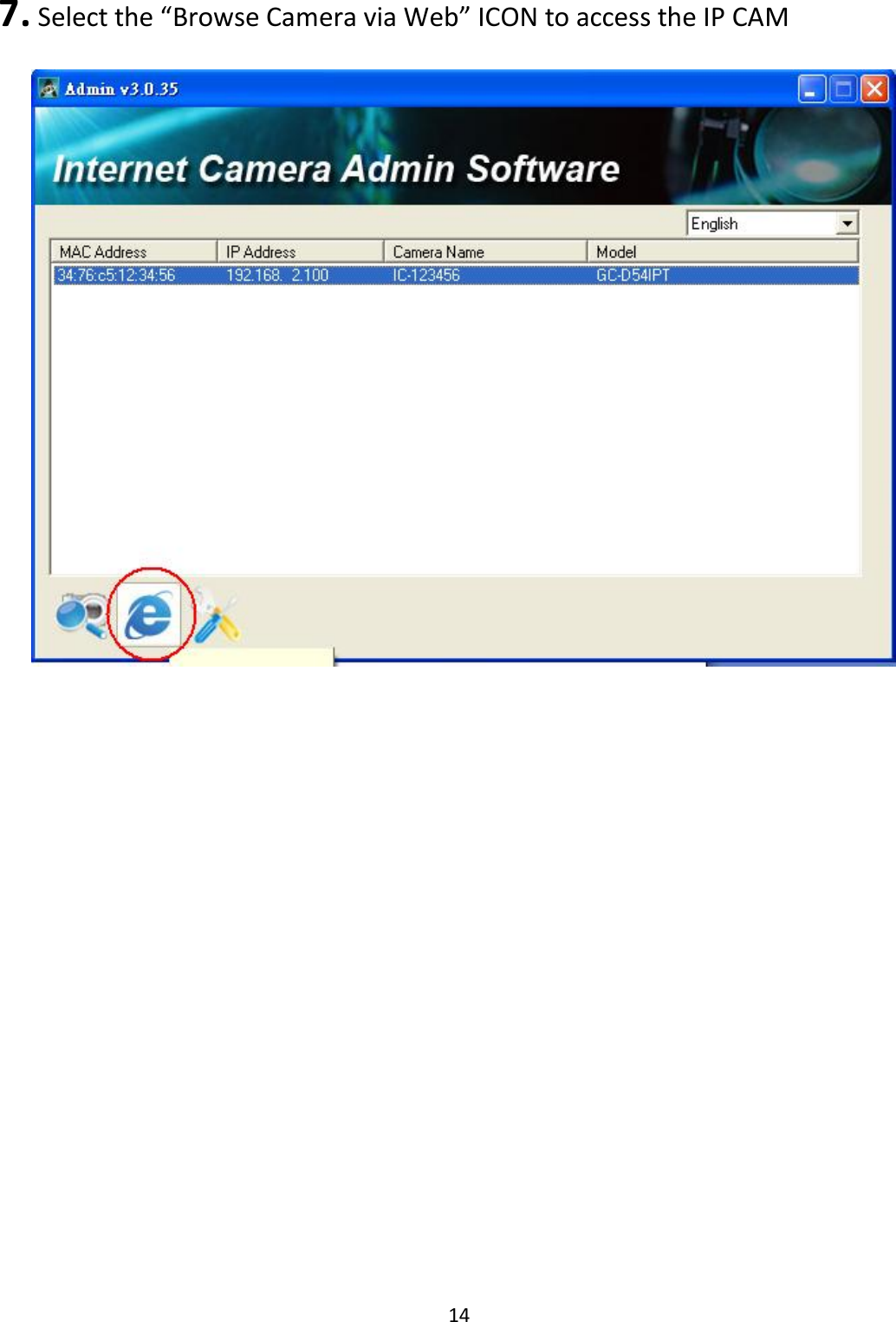
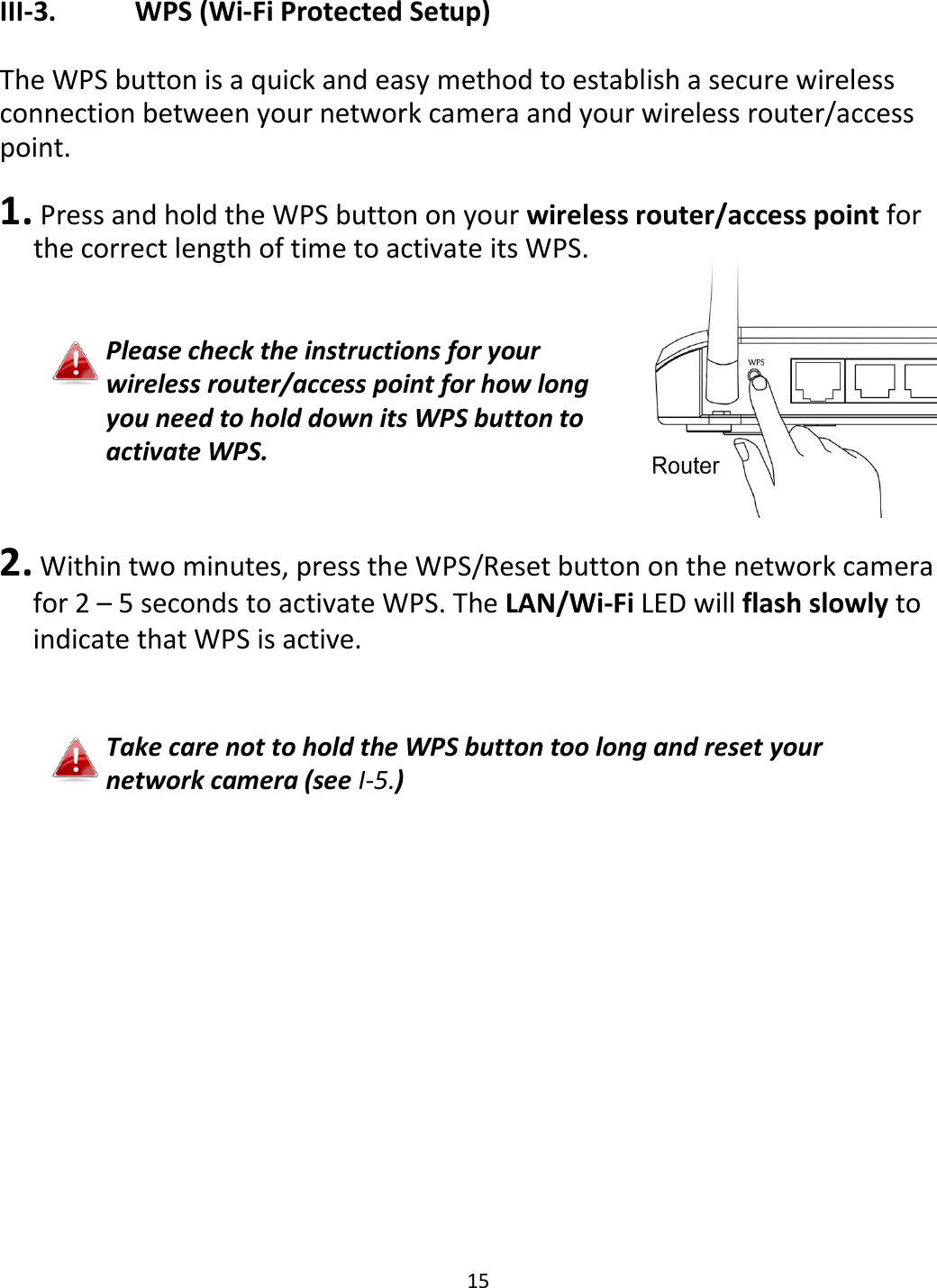
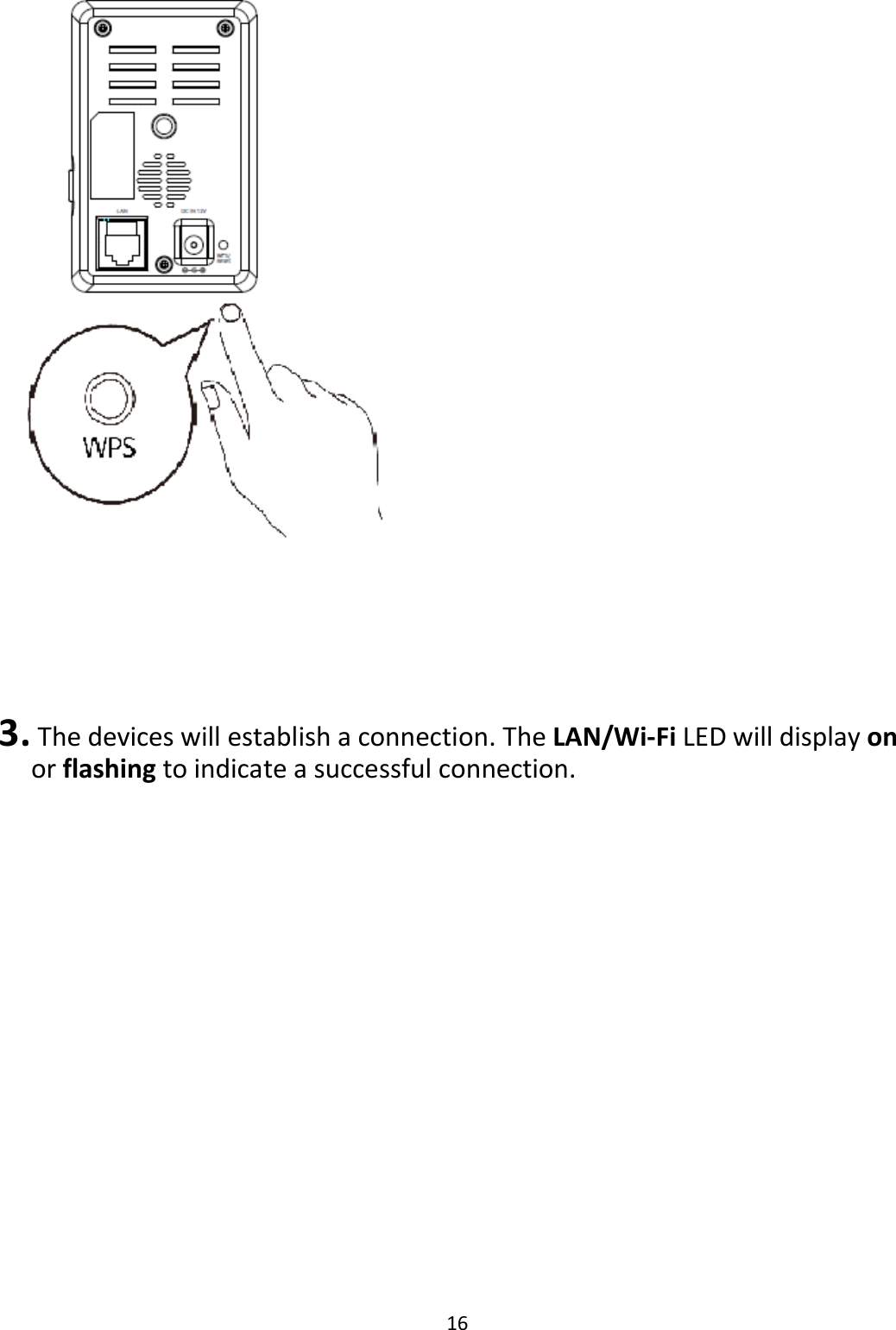
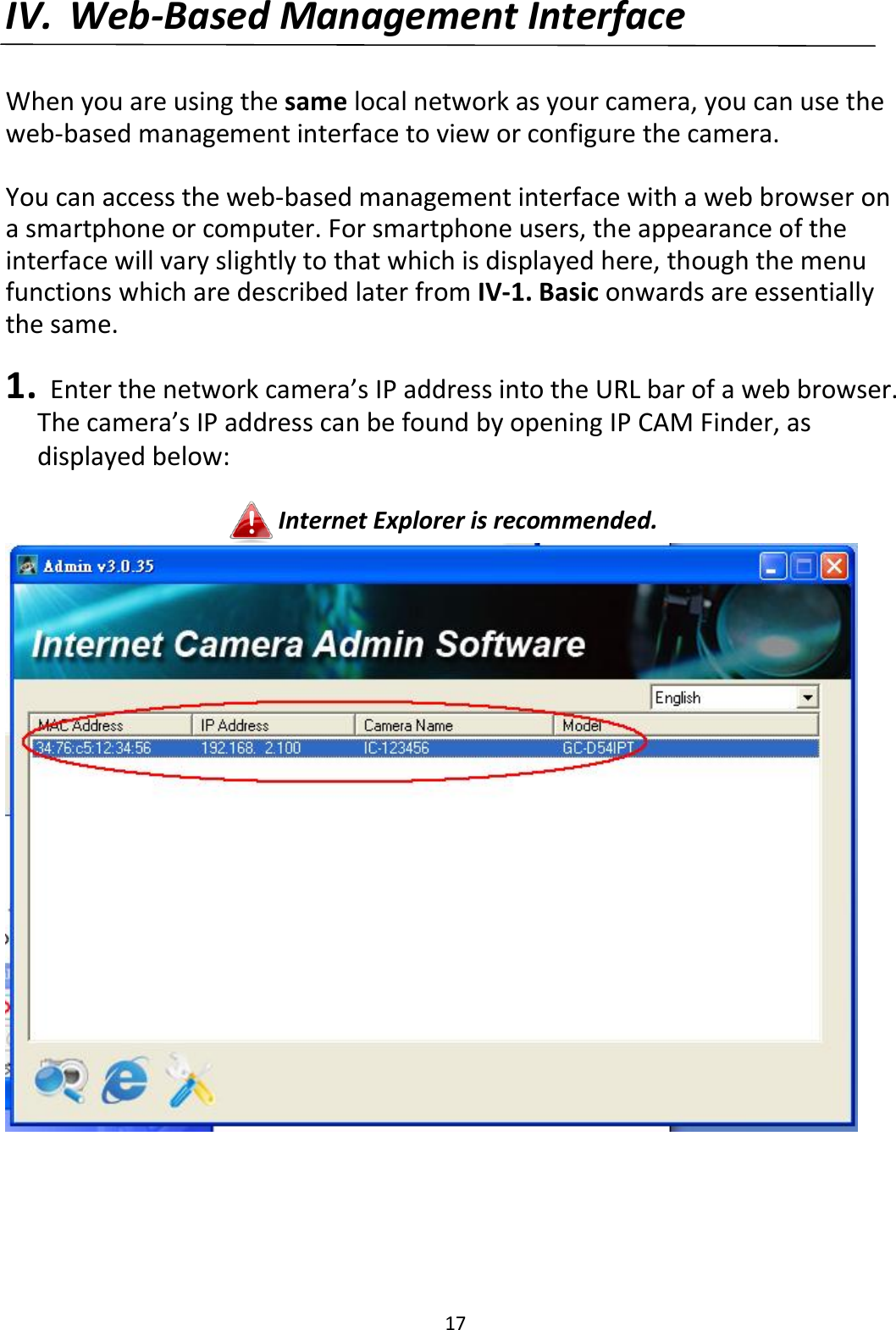
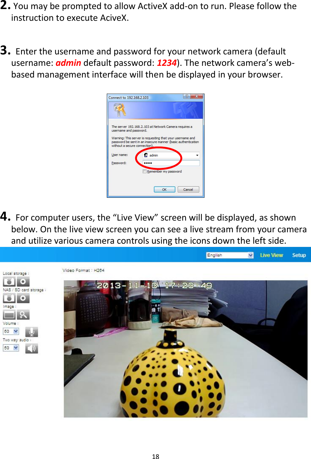
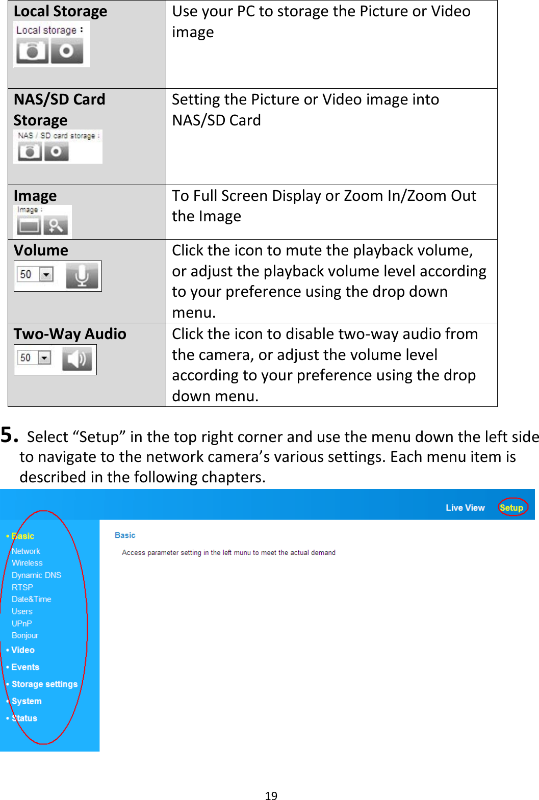
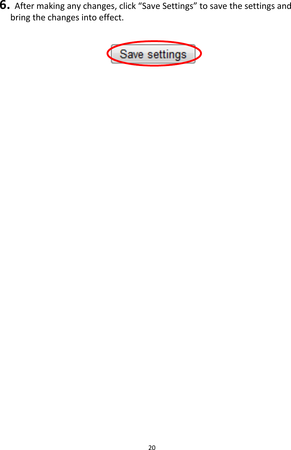
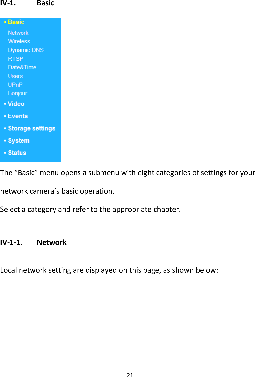
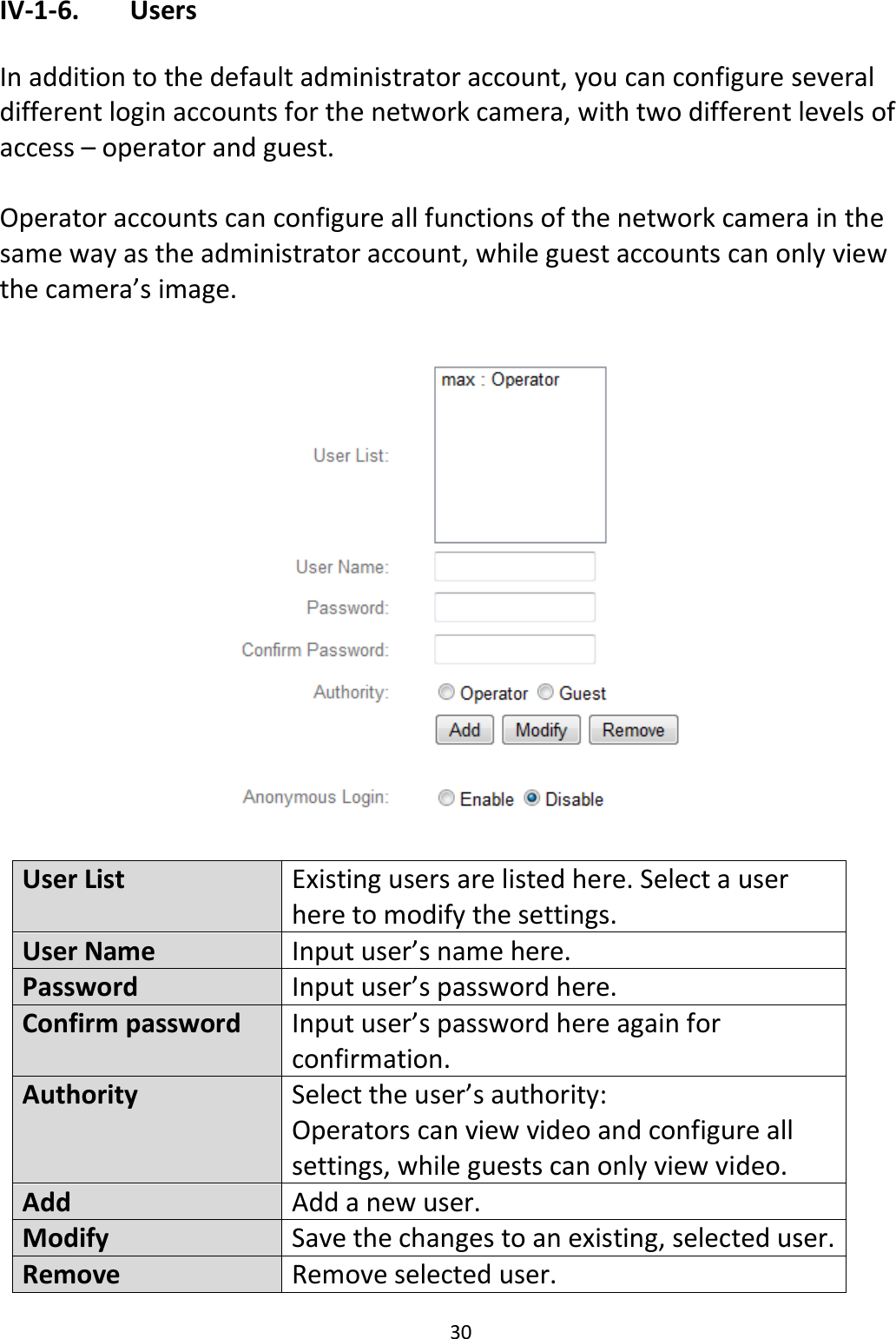
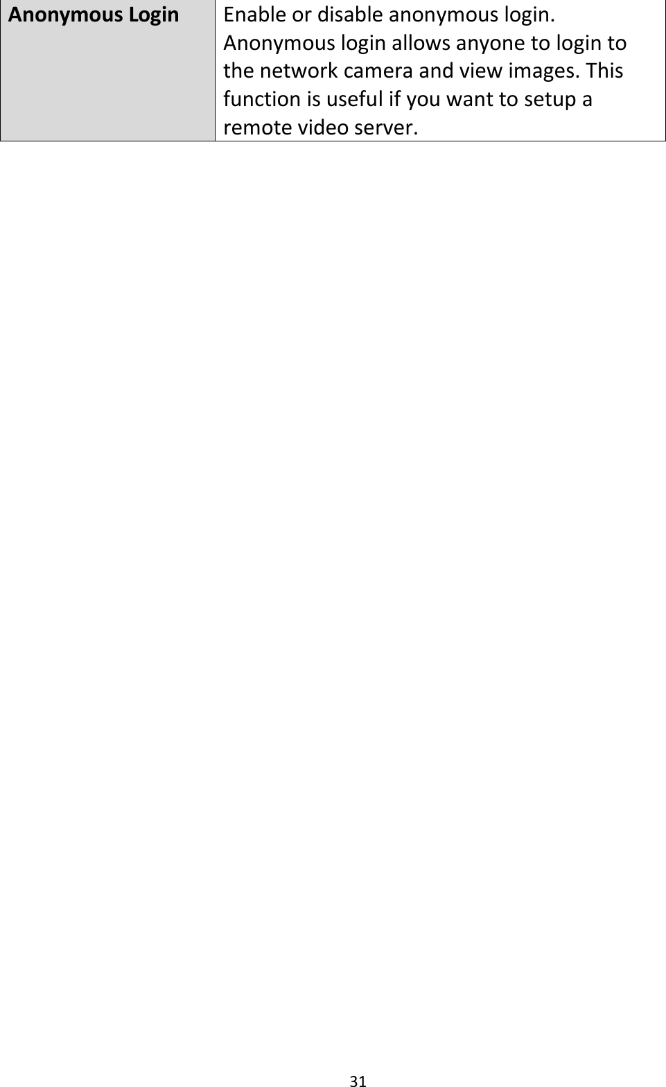
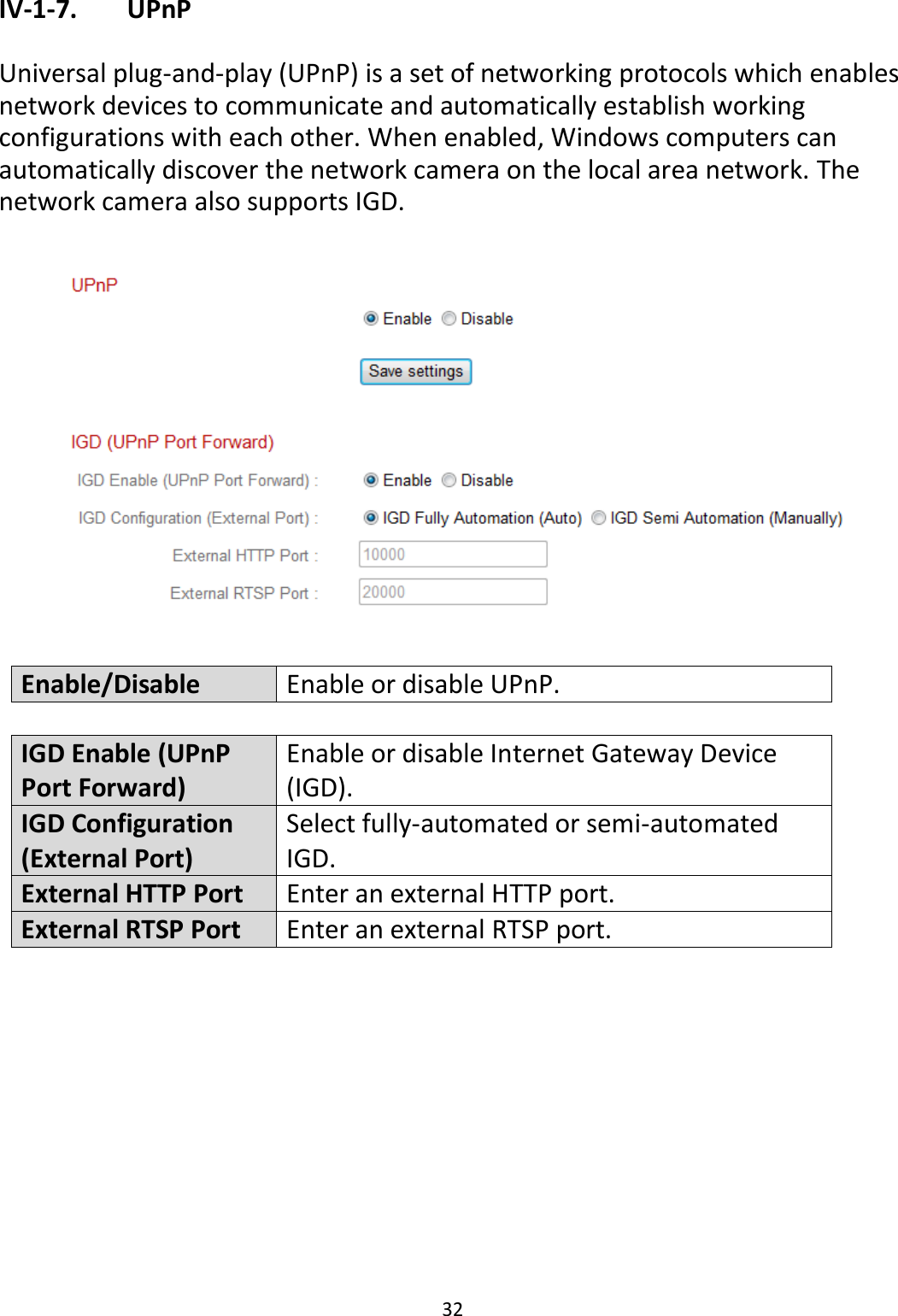
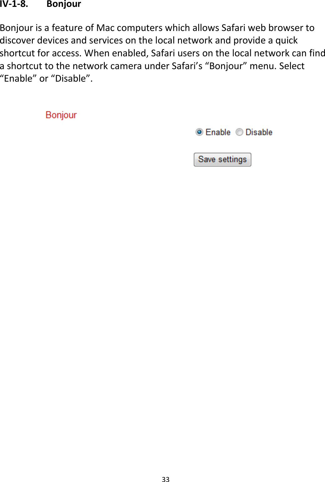
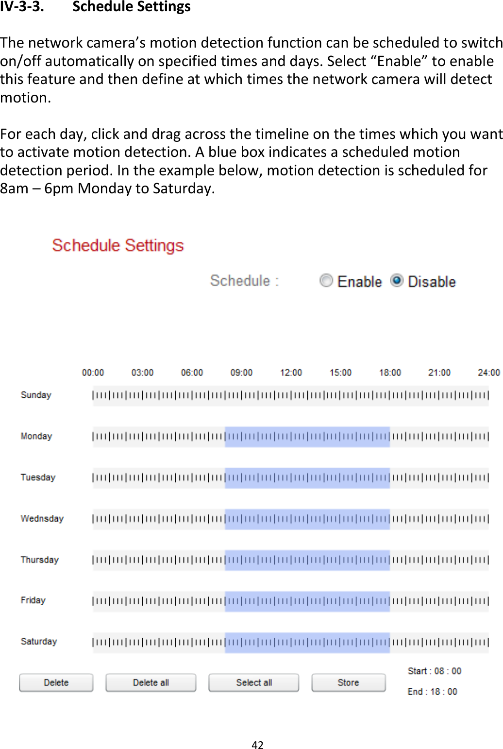
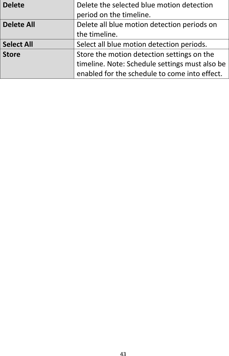
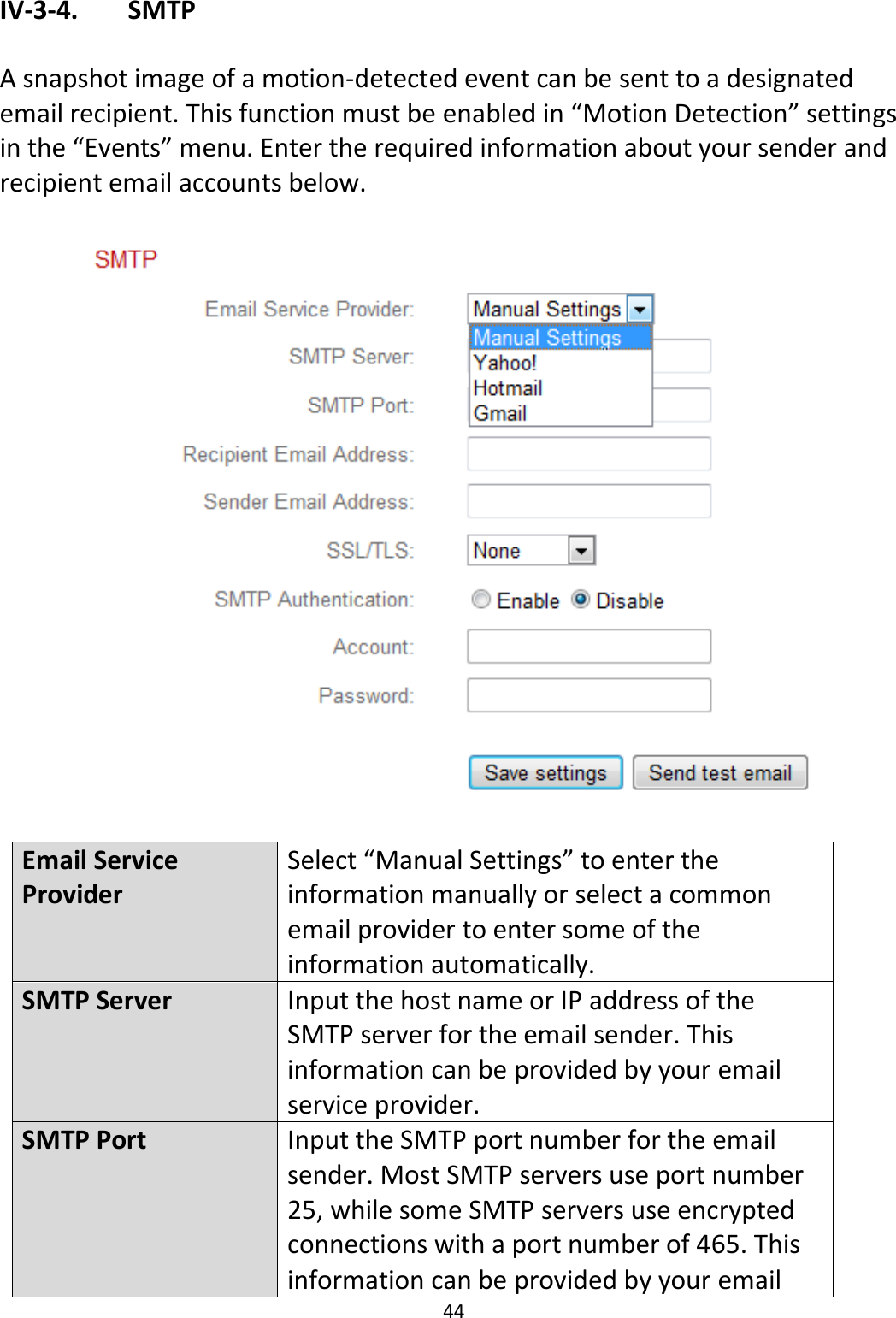
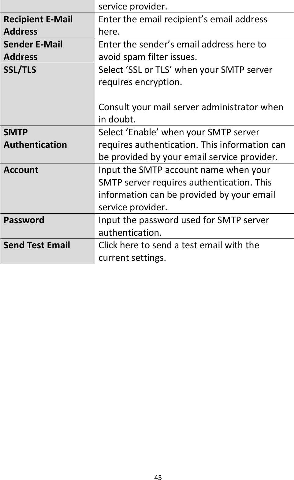
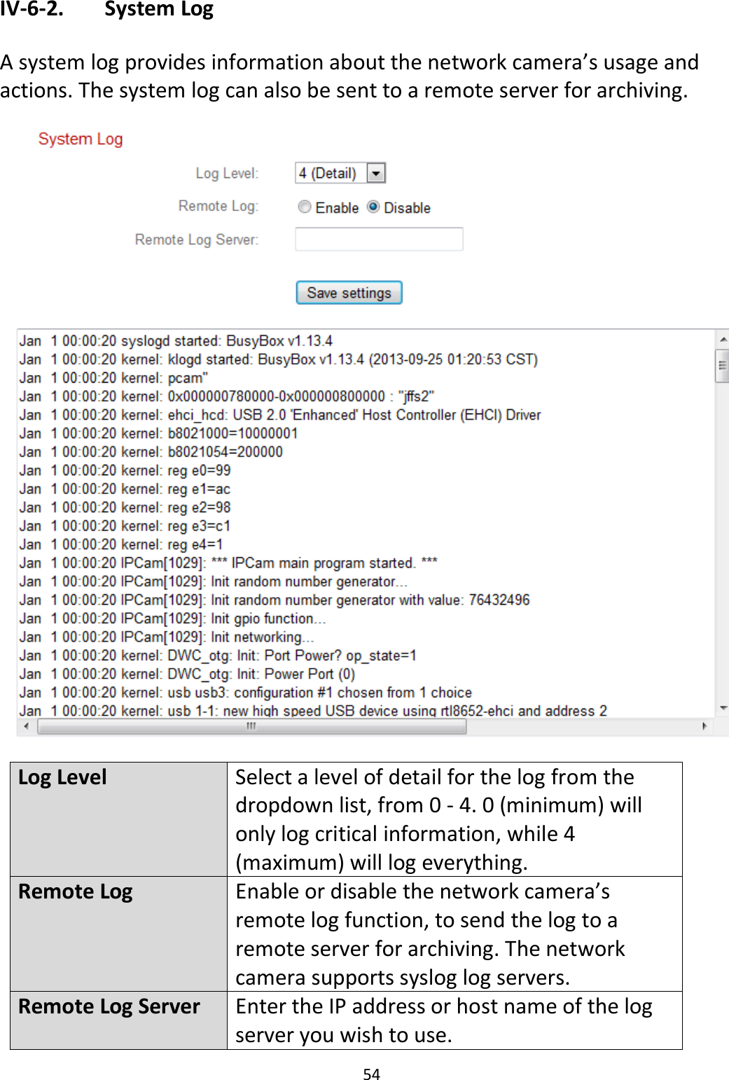
User Manual
Discussion / Help
Navigation