Edimax Technology Co 9530401309 Internet Camera User Manual
Edimax Technology Co Ltd Internet Camera
user manual
IC-3040IWT
User Manual
V1.0
2013-11
2
I. Product Information .............................................................................. 4
I-1. Package Contents ................................................................................................................ 4
I-2. System Requirements ......................................................................................................... 5
I-3. Back Panel .......................................................................................................................... 6
I-4. LED Status .......................................................................................................................... 6
I-5. Reset .................................................................................................................................. 7
II. Hardware Installation ............................................................................ 8
III. Camera Setup & IP CAM Finder ............................................................ 10
III-1. IP CAM Finder Network Camera Setup ............................................................................. 10
Windows ......................................................................................................................................... 10
III-3. WPS (Wi-Fi Protected Setup) ............................................................................................ 15
IV. Web-Based Management Interface ...................................................... 17
IV-1. Basic ................................................................................................................................. 21
IV-1-1. Network ........................................................................................................................... 21
IV-1-2. Wireless............................................................................................................................ 24
IV-1-2-1. Computer................................................................................................................ 25
IV-1-2-3. WPS ........................................................................................................................ 26
IV-1-3. Dynamic DNS .................................................................................................................... 27
IV-1-4. RTSP ................................................................................................................................. 28
IV-1-5. Date & Time ..................................................................................................................... 29
IV-1-6. Users ................................................................................................................................ 30
IV-1-7. UPnP ................................................................................................................................ 32
IV-1-8. Bonjour ............................................................................................................................ 33
IV-2. Video ................................................................................................................................ 34
IV-2-1. Video Settings................................................................................................................... 34
IV-2-2. Image Appearance ............................................................................................................ 36
IV-2-3. Night Vision ...................................................................................................................... 37
IV-3. Events............................................................................................................................... 38
IV-3-1. Motion Detection ............................................................................................................. 38
IV-3-2. Detection Region .............................................................................................................. 40
IV-3-3. Schedule Settings ............................................................................................................. 42
IV-3-4. SMTP ................................................................................................................................ 44
IV-3-5. FTP ................................................................................................................................... 46
IV-4. Storage Settings................................................................................................................ 47
3
The “Storage Settings” menu consists of five categories, “Storage Directory”, “Schedule Settings”,
“NAS Settings”, “SD Card Settings” and “File Management”. Select a category and follow the
appropriate chapter for more information. ..................................................................................... 47
IV-4-1. Storage Directory.............................................................................................................. 47
IV-4-2. Schedule Settings ............................................................................................................. 47
IV-4-3. NAS Settings ..................................................................................................................... 48
IV-4-4. SD card Settings ................................................................................................................ 49
IV-4-5. File Management.............................................................................................................. 49
IV-5. System .............................................................................................................................. 50
IV-5-1. Basic ................................................................................................................................. 50
IV-5-2. Advanced ......................................................................................................................... 51
IV-6. Status ............................................................................................................................... 52
IV-6-1. System Information .......................................................................................................... 52
IV-6-2. System Log ....................................................................................................................... 54
- End- ..................................................................................................... 55

4
I. Product Information
I-1. Package Contents
IC-3040IWT
QIG
CD-ROM
Power Adapter Ethernet Cable
5
I-2. System Requirements
- Intel Pentium 4 2.4GHz (above or similar)
- VGA card (1024*768 or above)
- CD-ROM Drive
- At least 128MB hard disk space (256 MB recommended)
- Windows 2000, XP, Vista, 7 or 8
- Web browser (Internet Explorer 7.0, Firefox 3.6, Chrome 10, Opera 11,
Safari 5 or above)
6
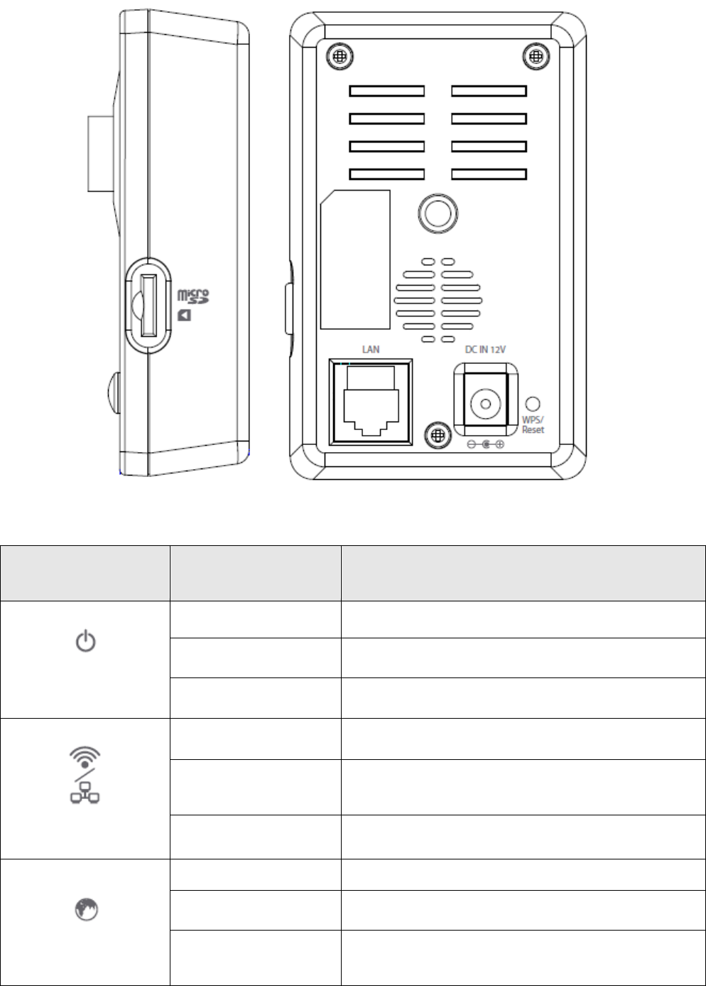
I-3. Back Panel
I-4. LED Status
LED ICON
LED Status
Description
(Power)
ON
Power On
Slow Flashing
During Power Up Stage
OFF
No Power Input
(LAN/Wi-Fi)
ON
Connected to LAN and/or Wi-Fi
Flashing
During data transmitting and
receiving
OFF
Neither LAN nor Wi-Fi connected
(Internet)
ON
Connected to Internet
Flashing
During Internet connection
OFF
Not connected to Internet

7
I-5. Reset
If you experience problems with your network camera, you can reset the
camera back to its factory default settings. This resets all settings back to
default.
1. Press and hold the WPS button found on the back panel for at least 10
seconds
2. Release the button when the orange LED is flashing quickly.
3. Wait for the network camera to restart. The camera is ready when the
green LED is on or flashing.
After reset, the LED will display off If there is no Ethernet
connection to the network camera from a router/access
point/switch.
8
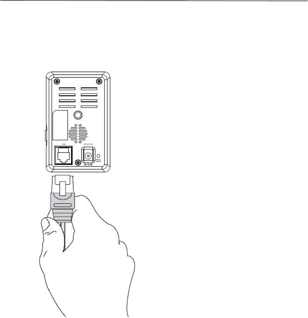
II. Hardware Installation
Follow the instructions below to ensure your camera is properly connected
and ready for setup.
1. Use an Ethernet cable to connect the network camera’s LAN port to a
router/switch/access point’s LAN port, as shown below.
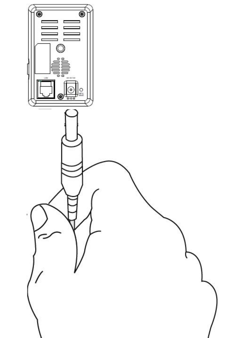
2. Connect the power adapter to the network camera’s power port and to a
power supply, as shown below.
9
3. Wait a moment for the camera to power on. The camera is ready when
the Power LED of the camera displays on or flashing. Please refer to III.
Camera Setup to setup your network camera.

10
III. Camera Setup & IP CAM Finder
Your network camera can be up and running in just a few minutes. First,
please follow the instructions below for Windows in III-1. Installing & Using IP
CAM Finder to install the IP CAM Finder software and connect your camera to
your wireless network.
Or you can follow III-3. WPS as an alternative method to connect your
network camera to your wireless network.
Then, you can use the web based management interface to watch a live
stream and further configure the camera if you need (see IV.).
Additionally, you can view the camera’s live image using either the cloud ID
(see V.), the 16 channel viewer software (see VI.), or the IP CAM smartphone
app (see VII).
III-1. IP CAM Finder Network Camera Setup
Ensure your computer is connected to the same router as the
network camera.
Windows
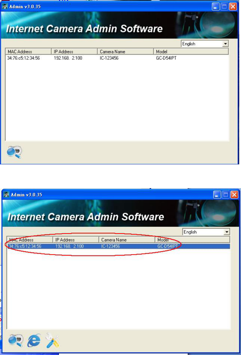
1. Insert the included CD into your CD-ROM drive
2. Find the “Internet Camera Admin Software” filename
“Setup_Admin_3.0.35_GLP.exe” and execute it
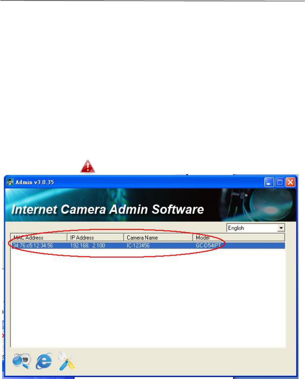
3. Find the IP CAM IP Address from the “Internet Camera Admin Software”
detail as the figure in below
11
4. Select the IP CAM found
12
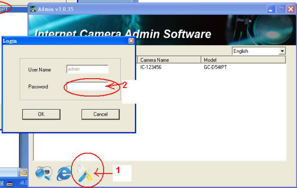
5. (1) Click the “Configure Camera” ICON and (2)key in the password then
“OK”
13
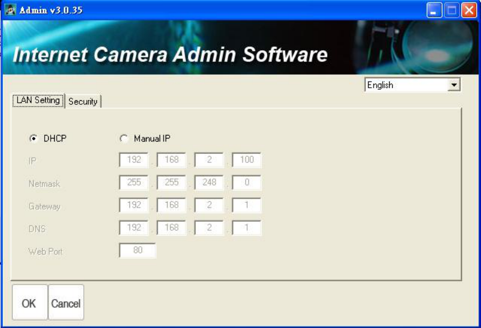
6. Press the “OK” button as the figure in below
14
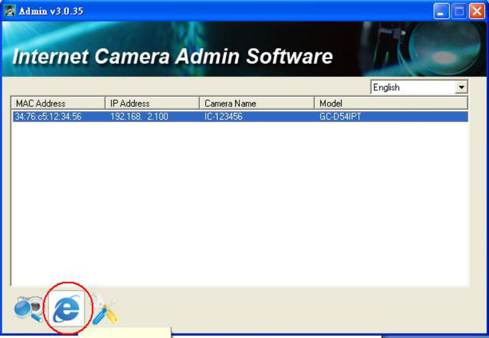
7. Select the “Browse Camera via Web” ICON to access the IP CAM
15
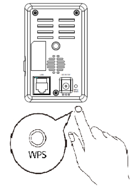
III-3. WPS (Wi-Fi Protected Setup)
The WPS button is a quick and easy method to establish a secure wireless
connection between your network camera and your wireless router/access
point.
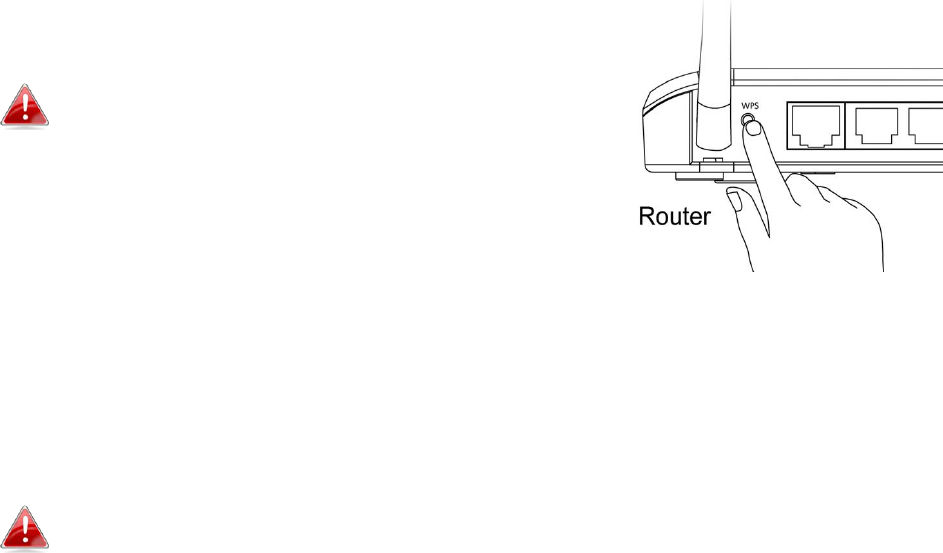
1. Press and hold the WPS button on your wireless router/access point for
the correct length of time to activate its WPS.
Please check the instructions for your
wireless router/access point for how long
you need to hold down its WPS button to
activate WPS.
2. Within two minutes, press the WPS/Reset button on the network camera
for 2 – 5 seconds to activate WPS. The LAN/Wi-Fi LED will flash slowly to
indicate that WPS is active.
Take care not to hold the WPS button too long and reset your
network camera (see I-5.)
16
3. The devices will establish a connection. The LAN/Wi-Fi LED will display on
or flashing to indicate a successful connection.
17
IV. Web-Based Management Interface
When you are using the same local network as your camera, you can use the
web-based management interface to view or configure the camera.
You can access the web-based management interface with a web browser on
a smartphone or computer. For smartphone users, the appearance of the
interface will vary slightly to that which is displayed here, though the menu
functions which are described later from IV-1. Basic onwards are essentially
the same.
1. Enter the network camera’s IP address into the URL bar of a web browser.
The camera’s IP address can be found by opening IP CAM Finder, as
displayed below:
Internet Explorer is recommended.

18
2. You may be prompted to allow ActiveX add-on to run. Please follow the
instruction to execute AciveX.
3. Enter the username and password for your network camera (default
username: admin default password: 1234). The network camera’s web-
based management interface will then be displayed in your browser.
4. For computer users, the “Live View” screen will be displayed, as shown
below. On the live view screen you can see a live stream from your camera
and utilize various camera controls using the icons down the left side.
19
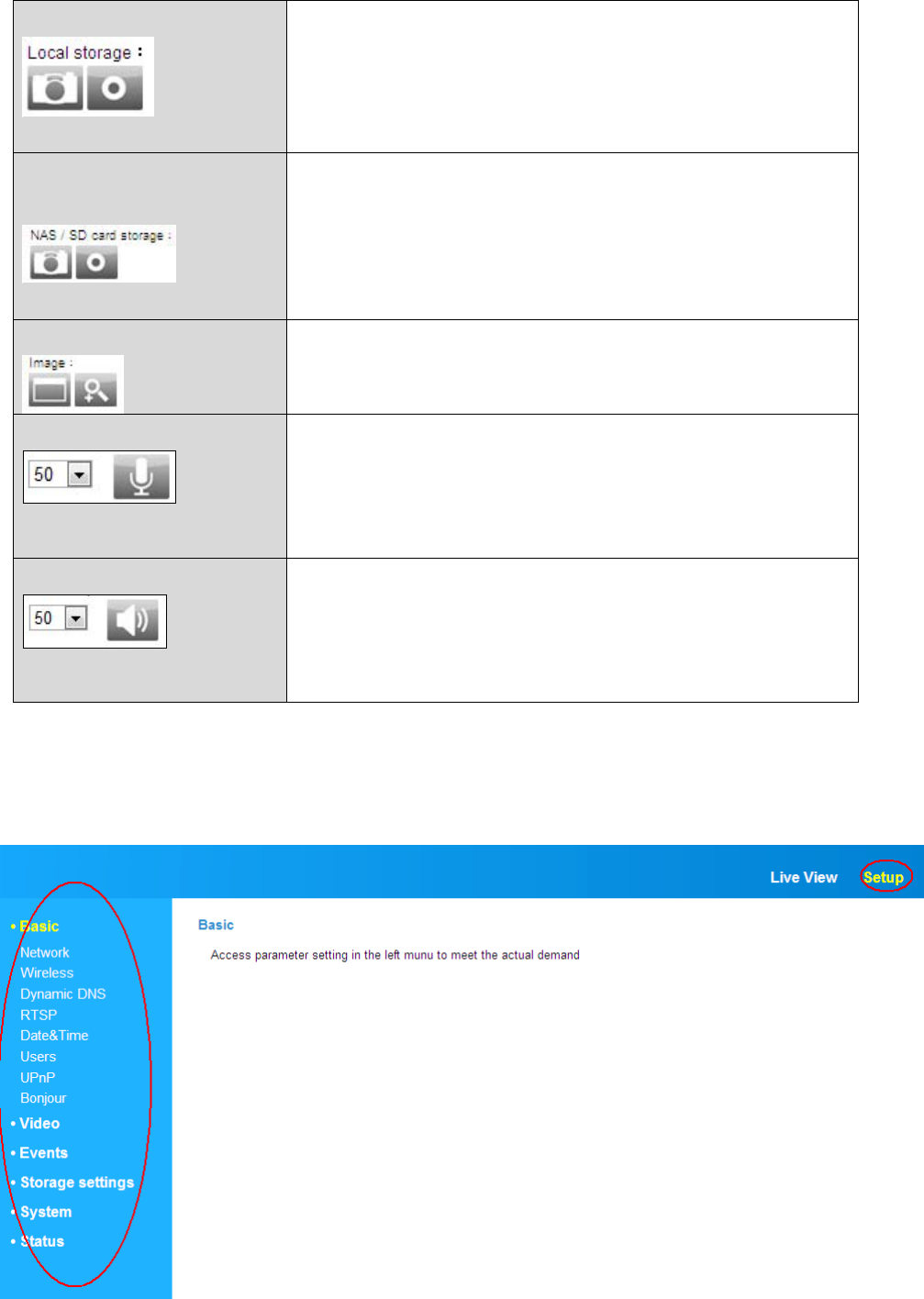
Local Storage
Use your PC to storage the Picture or Video
image
NAS/SD Card
Storage
Setting the Picture or Video image into
NAS/SD Card
Image
To Full Screen Display or Zoom In/Zoom Out
the Image
Volume
Click the icon to mute the playback volume,
or adjust the playback volume level according
to your preference using the drop down
menu.
Two-Way Audio
Click the icon to disable two-way audio from
the camera, or adjust the volume level
according to your preference using the drop
down menu.
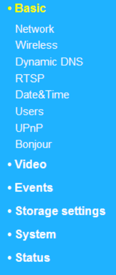
5. Select “Setup” in the top right corner and use the menu down the left side
to navigate to the network camera’s various settings. Each menu item is
described in the following chapters.

20
6. After making any changes, click “Save Settings” to save the settings and
bring the changes into effect.
21
IV-1. Basic
The “Basic” menu opens a submenu with eight categories of settings for your
network camera’s basic operation.
Select a category and refer to the appropriate chapter.
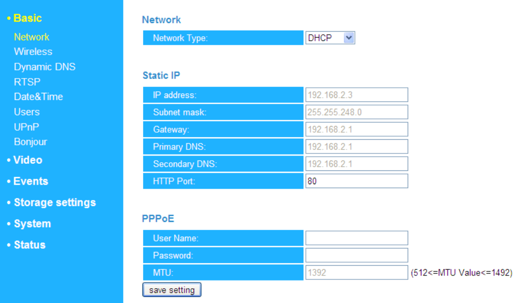
IV-1-1. Network
Local network setting are displayed on this page, as shown below:
22

23
Network Type
Select “DHCP” to automatically assign an IP
address to your network camera from your
router, or “Static IP” to manually set a static
IP address.
IP Address
Specify an IP address here, which will be the
IP address of your network camera.
Subnet Mask
Enter the subnet mask of the IP address.
Gateway
Enter the gateway address of your network.
Primary DNS
Enter the IP address of your primary DNS
server.
Secondary DNS
Enter the IP address of your secondary DNS
server (optional).
HTTP Port
You can edit the HTTP port number to any
value between 1024 – 65535. The default
value is 80.
24
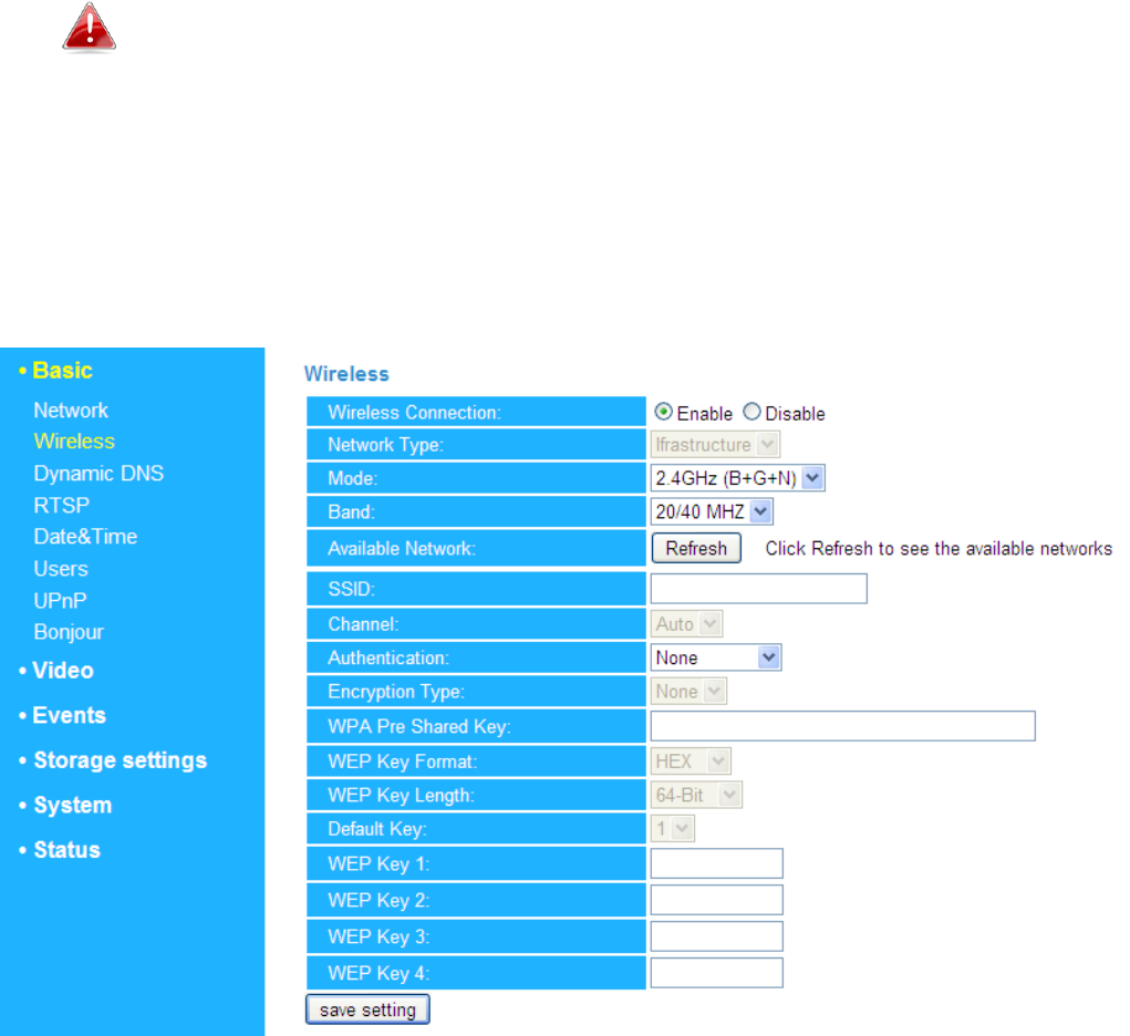
IV-1-2. Wireless
The wireless page allows you to configure settings for your network camera’s
wireless connection. For Windows users, your wireless connection should
have been set up already using IP CAM Finder, though you can still use this
page to revise the settings if you need.
Mac users need to configure these settings manually since IP CAM Finder on
Mac will not set up your camera’s wireless connection. A quick guide to set up
your network camera’s wireless connection using a smartphone or a
computer is included below.
Mac users setting their network camera’s wireless connection for
the first time please ensure your network camera is connected to
your router/access point/switch via Ethernet cable.
You can also use the “wireless” page for Wi-Fi Protected Setup (WPS): to
either activate push-button WPS (the same effect as physically pushing the
hardware WPS button built into the camera), or PIN code WPS (using a PIN
code for verification between the two wireless devices for additional security.)
25
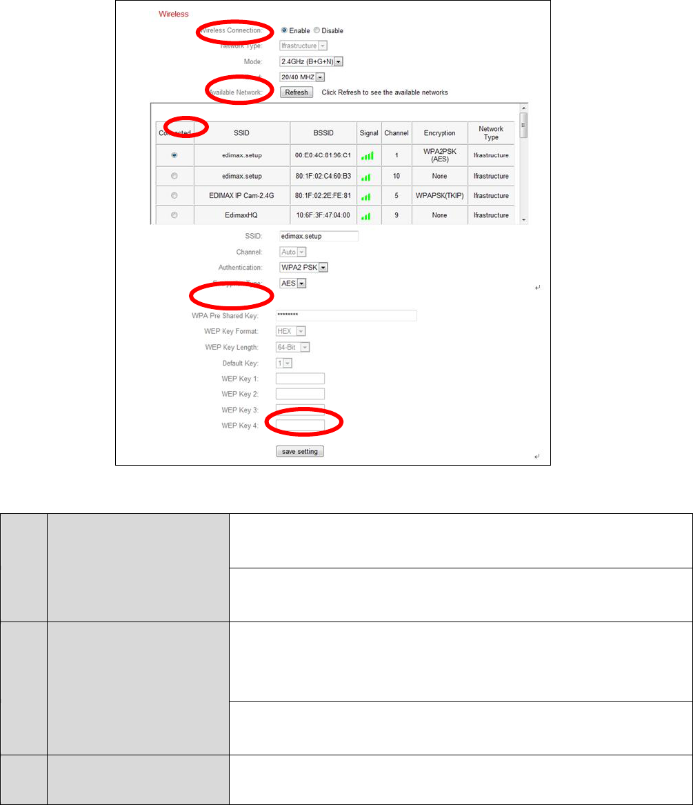
IV-1-2-1. Computer
1. Configure the wireless settings A – E shown in the table below:
2. After the settings are saved, remove the Ethernet cable from your
network camera. Your camera should now be connected to your Wi-Fi.
A
Wireless
Connection
Select “Enable” to enable the wireless
connection.
B
Available
Network
Click “Refresh” to display all available Wi-Fi
networks.
C
Connected
Select your Wi-Fi network from the list. This is the
wireless network which your camera will connect
to.
D
WPA Pre Shared
Key
Enter your Wi-Fi password.
E
Save Settings
Click “Save Settings” to save your settings.
A
B
C
D
E
26
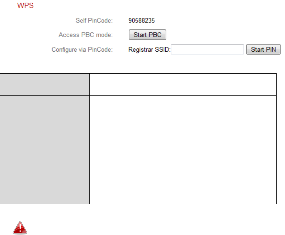
IV-1-2-3. WPS
WPS (Wi-Fi Protected Setup) is a quick and easy way to set up wireless
connections between compatible devices. Use the “Start PBC” or “Start PIN”
button to activate WPS on your network camera. Your network camera’s WPS
PIN code is also listed next to “Self PinCode”.
Self PinCode
Your network camera’s WPS PIN code is listed
here.
Access PBC Mode
Click “Start PBC” to activate push-button WPS
on your network camera. This has the same
effect as physically pushing the built-in
hardware WPS button.
Configure via
PinCode
Enter the SSID you wish to connect to and
click “Start PIN” to activate PIN code WPS.
You will then need to enter the network
camera’s “Self PinCode” into your wireless
router’s web U.I. and activate your router’s
PIN code WPS.
Please refer to your wireless router’s instructions for help
accessing its web-based interface and activating WPS.
27
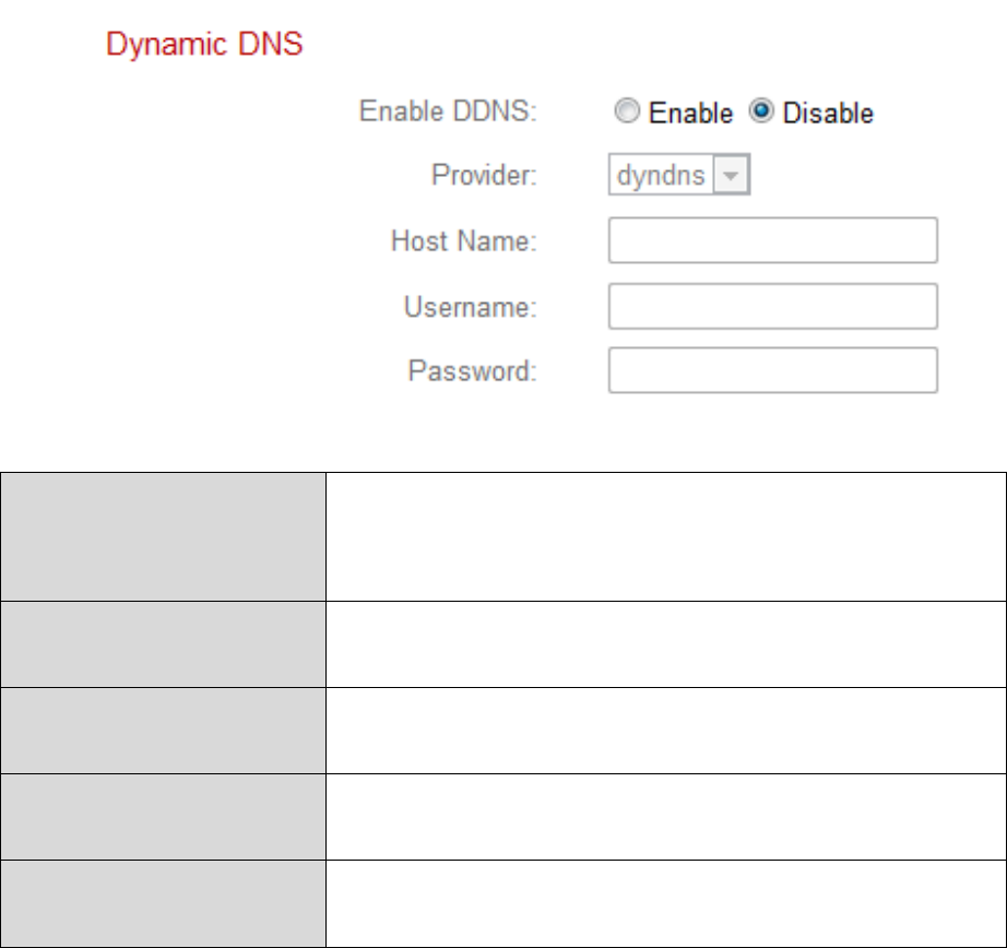
IV-1-3. Dynamic DNS
Dynamic DNS (DDNS) is a service which provides a hostname-to-IP service for
dynamic IP users. If your Internet service provider didn’t issue a fixed IP
address, you can use a third-party dynamic DNS provider to map your current
IP address to a fixed IP address. Several free or paid DDNS services are
available online, please use the information provided by your DDNS provider
to configure the settings on this page.
Enable DDNS
Select “Enable” to enable DDNS functionality,
or select “Disable” to disable DDNS
functionality.
Provider
Select your dynamic DNS service provider
from the dropdown menu.
Host Name
Enter the hostname you registered with the
DDNS service provider.
User Name
Enter the user name you registered with the
DDNS service provider.
Password
Enter the password you registered with the
DDNS service provider.
28
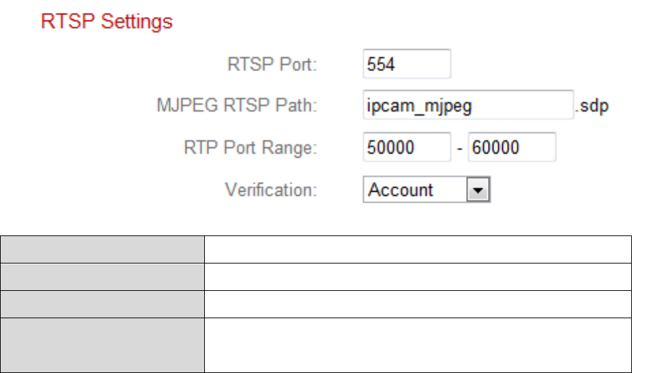
IV-1-4. RTSP
Real Time Streaming Protocol (RTSP) enables the network camera to be used
with a streaming media server. Enter the required RTSP settings.
RTSP Port
Enter the RTSP port.
MJPEG RTSP Path
Enter the MJPEG RTSP path.
RTP Port Range
Enter the RTSP port range.
Verification
Select a verification type from the drop down
menu.
29
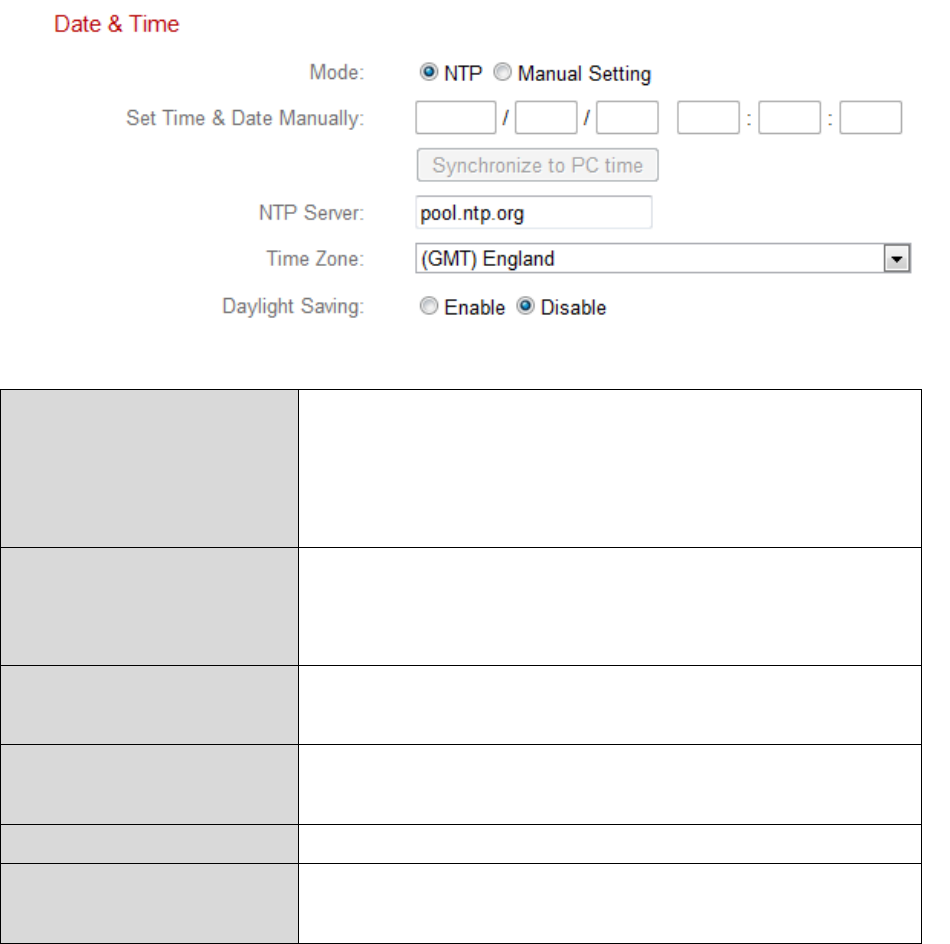
IV-1-5. Date & Time
You can set and adjust the network camera’s system time and date on this
page. Maintaining a correct system time is particularly important for recorded
video organization/playback.
Mode
Select ”NTP” or “Manual Setting”. NTP
(Network Time Protocol) can set and maintain
the time and date automatically via an NTP
server on the local network, if available.
Set Time & Date
Manually
For manual setting mode, enter the correct
time and date in the following format:
YYYY/MM/DD HH:MM:SS
Synchronize to PC
time
Click here to automatically enter the same
time and date as your computer.
NTP Server
For NTP mode, enter the NTP server’s
hostname or IP address.
Time Zone
Select the correct time zone.
Daylight Saving
Enable or disable daylight saving according
your local time zone.
30
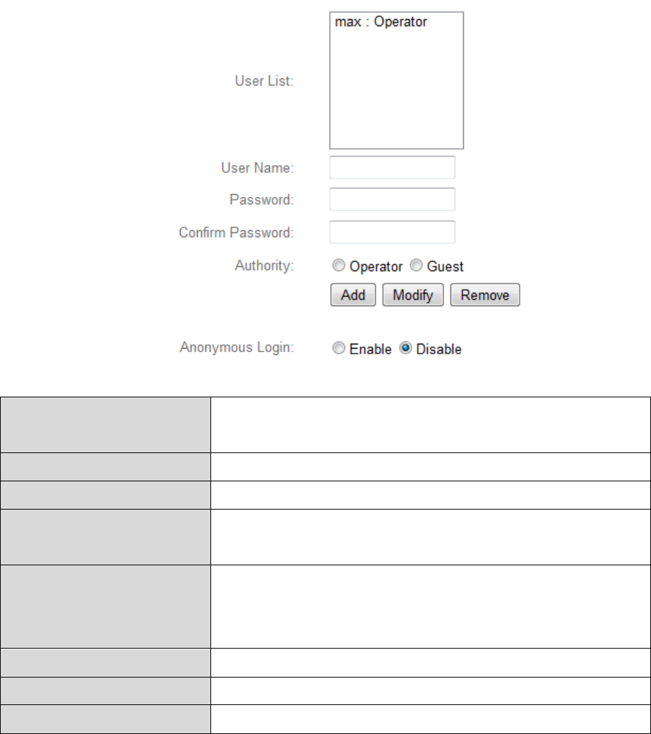
IV-1-6. Users
In addition to the default administrator account, you can configure several
different login accounts for the network camera, with two different levels of
access – operator and guest.
Operator accounts can configure all functions of the network camera in the
same way as the administrator account, while guest accounts can only view
the camera’s image.
User List
Existing users are listed here. Select a user
here to modify the settings.
User Name
Input user’s name here.
Password
Input user’s password here.
Confirm password
Input user’s password here again for
confirmation.
Authority
Select the user’s authority:
Operators can view video and configure all
settings, while guests can only view video.
Add
Add a new user.
Modify
Save the changes to an existing, selected user.
Remove
Remove selected user.

31
Anonymous Login
Enable or disable anonymous login.
Anonymous login allows anyone to login to
the network camera and view images. This
function is useful if you want to setup a
remote video server.
32
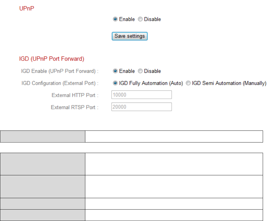
IV-1-7. UPnP
Universal plug-and-play (UPnP) is a set of networking protocols which enables
network devices to communicate and automatically establish working
configurations with each other. When enabled, Windows computers can
automatically discover the network camera on the local area network. The
network camera also supports IGD.
Enable/Disable
Enable or disable UPnP.
IGD Enable (UPnP
Port Forward)
Enable or disable Internet Gateway Device
(IGD).
IGD Configuration
(External Port)
Select fully-automated or semi-automated
IGD.
External HTTP Port
Enter an external HTTP port.
External RTSP Port
Enter an external RTSP port.
33
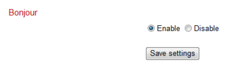
IV-1-8. Bonjour
Bonjour is a feature of Mac computers which allows Safari web browser to
discover devices and services on the local network and provide a quick
shortcut for access. When enabled, Safari users on the local network can find
a shortcut to the network camera under Safari’s “Bonjour” menu. Select
“Enable” or “Disable”.
34
IV-2. Video
The “Video” menu consists of three categories for configuring the network
camera’s video settings. Select an item from the submenu and refer to the
appropriate following chapter.
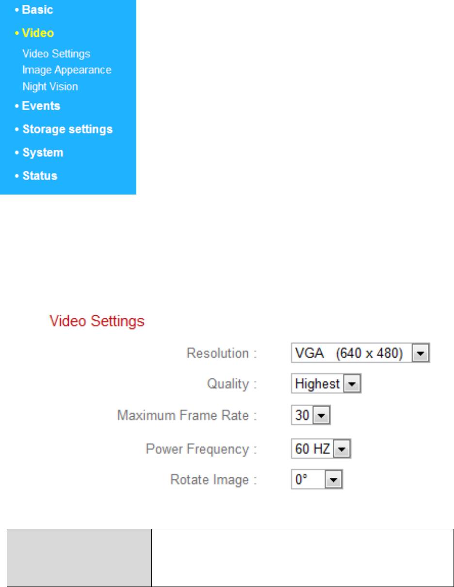
IV-2-1. Video Settings
The “Video Settings” page enables you to modify the network camera’s
resolution and frame rate settings.
Resolution
Select a video resolution from the dropdown
menu. A higher resolution provides more
detailed video but requires more bandwidth.

35
Quality
Select a quality level from the drop down
menu. Higher quality requires more
bandwidth.
Maximum Frame
rate
Select the maximum video frame rate. A
higher frame rate provides smoother video,
but also requires more bandwidth.
Note: In dark environments, the network
camera will automatically lower the frame
rate to provide a better video quality, by
using a longer exposure time.
Power frequency
Adjust the power frequency to 50 Hz or 60 Hz
frequency depending on your local region, in
order to reduce flicker/improve playback in
your videos.
Rotate Image
Select 180 to rotate your network camera’s
video by 180 degress.

36
IV-2-2. Image Appearance
The “Image Appearance” page allows you to adjust various parameters
relating to the network camera’s image appearance using the sliders shown
below.
Brightness/
Contrast/
Saturation/
Sharpness/
Hue
Click and drag the blue lever to change the
value according to your preference for each
category.
Reset to default
Click to reset all settings back to the default
value of 50.
Save value
Save changes.

37
IV-2-3. Night Vision
Night-vision allows your network camera to capture images in dark
environments by using infra-red LEDs. Auto-switch will detect light levels in
your network camera’s environment and automatically switch to night-vision
in low light. Select “Enable” or “Disable” for night-vision auto-switch.
38
IV-3. Events
Select an item from the “Events” menu and refer to the appropriate following
chapter. You can configure settings for motion detection, scheduling, SMTP
and FTP.
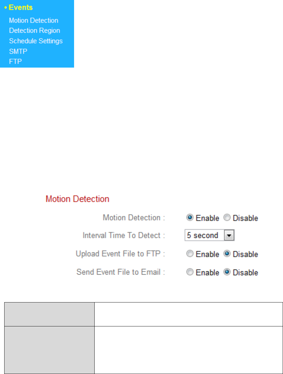
IV-3-1. Motion Detection
The network camera features a motion detection function and various options
for (motion detection) events notification. On this page you can enable or
disable motion detection, event FTP upload and event emails as well as set
the motion detection time interval. Motion detection regions can be
configured according to your preference on the “Detection Region” page (see
next chapter).
Motion Detection
Enable or disable the motion detection
function of your network camera.
Motion Detection
Interval
The motion detection interval time
determines the length of time the camera
must detect motion for in order to class the
motion as an event. To detect minor motion,

39
select a shorter time. A longer time will ignore
minor motions. Select your desired time from
the drop down menu.
Upload Event File to
FTP
A snapshot image of a detected event can be
sent to a designated FTP server. Select
“Enable” or “Disable” for this function. When
enabled, you need to configure the FTP server
information on the “FTP” page of the “Events”
menu.
Send Event File to
Email
A snapshot image of a detected event can be
sent to a designated email recipient. Select
“Enable” or “Disable” for this function. When
enabled, you need to configure the SMTP
server information on the “SMTP” page of the
“Events” menu.
40
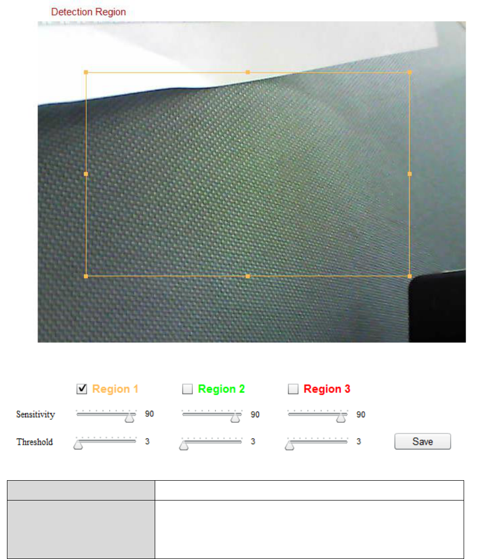
IV-3-2. Detection Region
When using the network camera’s motion detection function, you can specify
the area in the video where the network camera should be sensitive to
motion. Motion outside of the detection region will be ignored by the
network camera. This is useful to avoid false alarms.
Item
Description
Region 1 /
Region 2 /
Region 3
Check the box to enable up to three motion
detection regions. A color-coded rectangle
will appear on the video view for each

41
enabled region. Adjust the size and position
of each box according to your preference by
clicking and dragging inside the box (move) or
on the edges (resize).
Sensitivity
Adjust the sensitivity level of motion
detection for each region. A higher value will
trigger the alarm for minor motion in the
video and vice-versa. You can reduce the
sensitivity level if you receive unnecessary
event notifications.
Threshold
Adjust the motion detection threshold level
for each region. A higher value will trigger the
alarm for large objects in the video, a lower
value will trigger the alarm for smaller
objects.
Save
Save your settings.

42
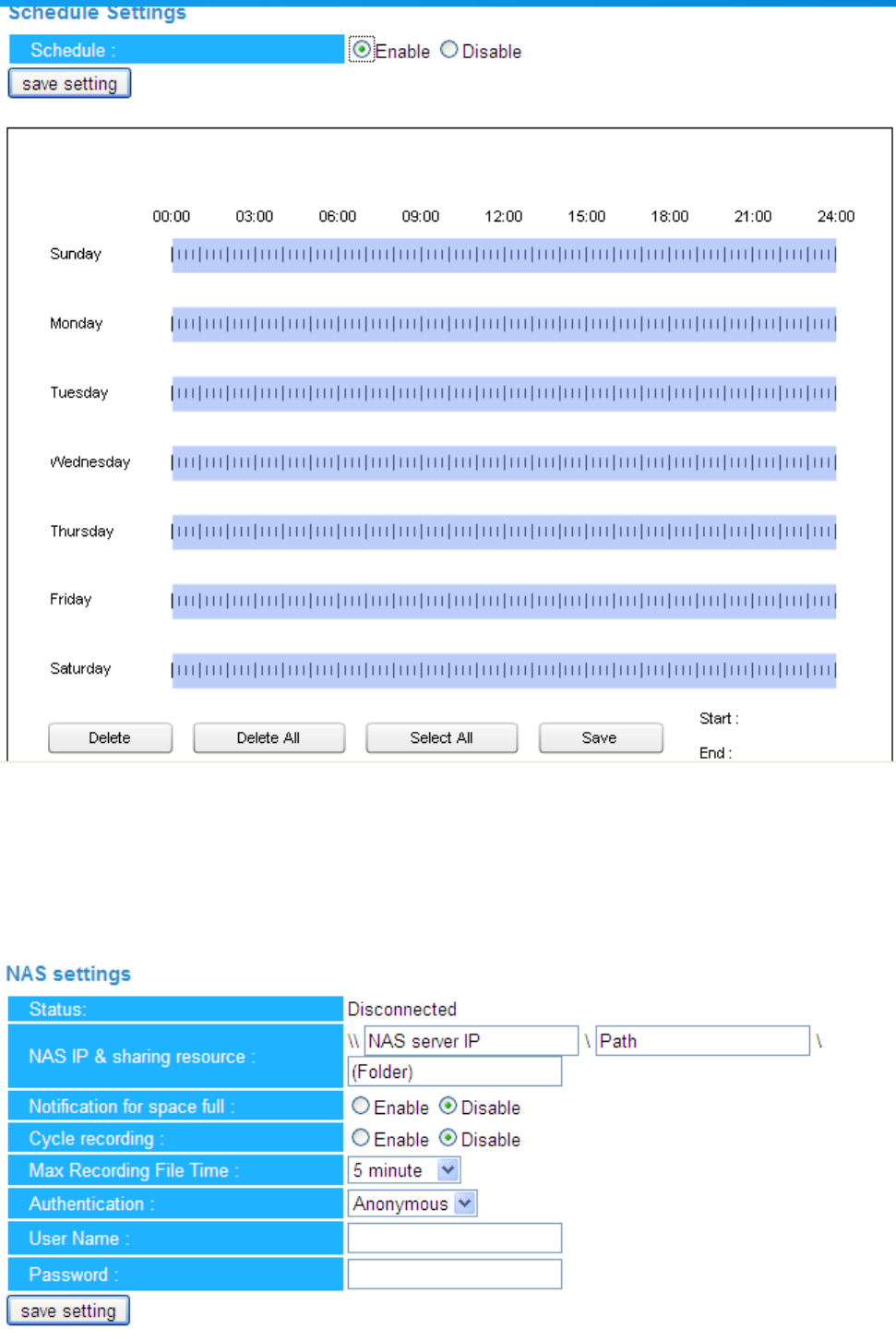
IV-3-3. Schedule Settings
The network camera’s motion detection function can be scheduled to switch
on/off automatically on specified times and days. Select “Enable” to enable
this feature and then define at which times the network camera will detect
motion.
For each day, click and drag across the timeline on the times which you want
to activate motion detection. A blue box indicates a scheduled motion
detection period. In the example below, motion detection is scheduled for
8am – 6pm Monday to Saturday.

43
Delete
Delete the selected blue motion detection
period on the timeline.
Delete All
Delete all blue motion detection periods on
the timeline.
Select All
Select all blue motion detection periods.
Store
Store the motion detection settings on the
timeline. Note: Schedule settings must also be
enabled for the schedule to come into effect.
44
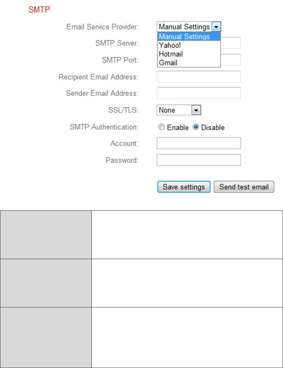
IV-3-4. SMTP
A snapshot image of a motion-detected event can be sent to a designated
email recipient. This function must be enabled in “Motion Detection” settings
in the “Events” menu. Enter the required information about your sender and
recipient email accounts below.
Email Service
Provider
Select “Manual Settings” to enter the
information manually or select a common
email provider to enter some of the
information automatically.
SMTP Server
Input the host name or IP address of the
SMTP server for the email sender. This
information can be provided by your email
service provider.
SMTP Port
Input the SMTP port number for the email
sender. Most SMTP servers use port number
25, while some SMTP servers use encrypted
connections with a port number of 465. This
information can be provided by your email

45
service provider.
Recipient E-Mail
Address
Enter the email recipient’s email address
here.
Sender E-Mail
Address
Enter the sender’s email address here to
avoid spam filter issues.
SSL/TLS
Select ‘SSL or TLS’ when your SMTP server
requires encryption.
Consult your mail server administrator when
in doubt.
SMTP
Authentication
Select ‘Enable’ when your SMTP server
requires authentication. This information can
be provided by your email service provider.
Account
Input the SMTP account name when your
SMTP server requires authentication. This
information can be provided by your email
service provider.
Password
Input the password used for SMTP server
authentication.
Send Test Email
Click here to send a test email with the
current settings.
46
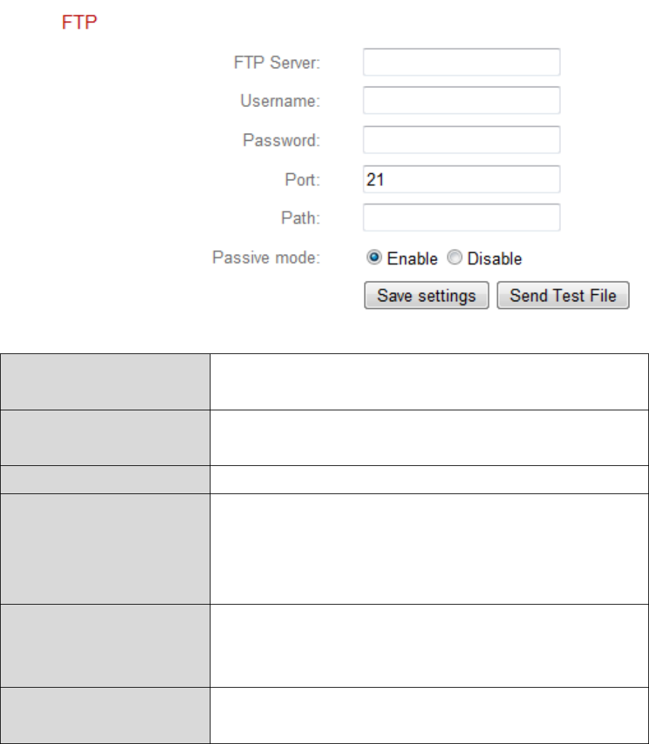
IV-3-5. FTP
A snapshot image of a detected event can be sent to a designated FTP server.
This function must be enabled in “Motion Detection” settings in the “Events”
menu. Enter the required information about your FTP server below.
FTP Server
Enter the IP address or host name of the FTP
server.
User Name
Enter the user name required by the FTP
server.
Password
Enter the password of the FTP server.
Port
Enter the port number of the FTP server. This
value should be an integer between 1 and
65535. Please don’t change this value unless
advised by the FTP server’s administrator.
Path
Enter a path (folder) to save files on the FTP
server. If blank, files will be saved in the FTP
server’s default root folder.
Passive mode
Enable or disable passive mode according to
your FTP server.
47
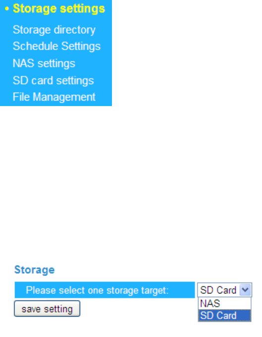
IV-4. Storage Settings
The “Storage Settings” menu consists of five categories, “Storage
Directory”, “Schedule Settings”, “NAS Settings”, “SD Card Settings” and “File
Management”. Select a category and follow the appropriate chapter for more
information.
IV-4-1. Storage Directory
The Storage Directory allow you setting the destination of file storage
either SD Card or NAS.
IV-4-2. Schedule Settings
The Schedule Settings allow you to enable or disable this function. After
you enable the Schedule Settings, you can setting the interval time by quarter
hour time unit.
48
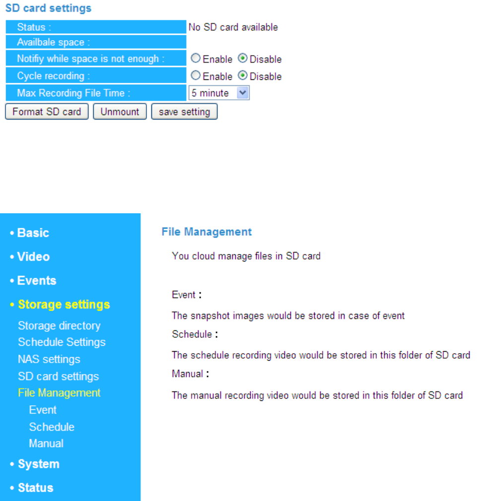
IV-4-3. NAS Settings
The NAS Settings allow you to define the NAS location.
49
IV-4-4. SD card Settings
The SD Card Setting allow you to format/unmount and save setting of
the SD card. SD Card memory notify and cycle recording also configurable.
IV-4-5. File Management
The File Management let you manage files in SD Card.
50
IV-5. System
The “System” menu consists of three categories, “Basic”, “Advanced” and
“Cloud Service”. Select a category and follow the appropriate chapter for
more information.
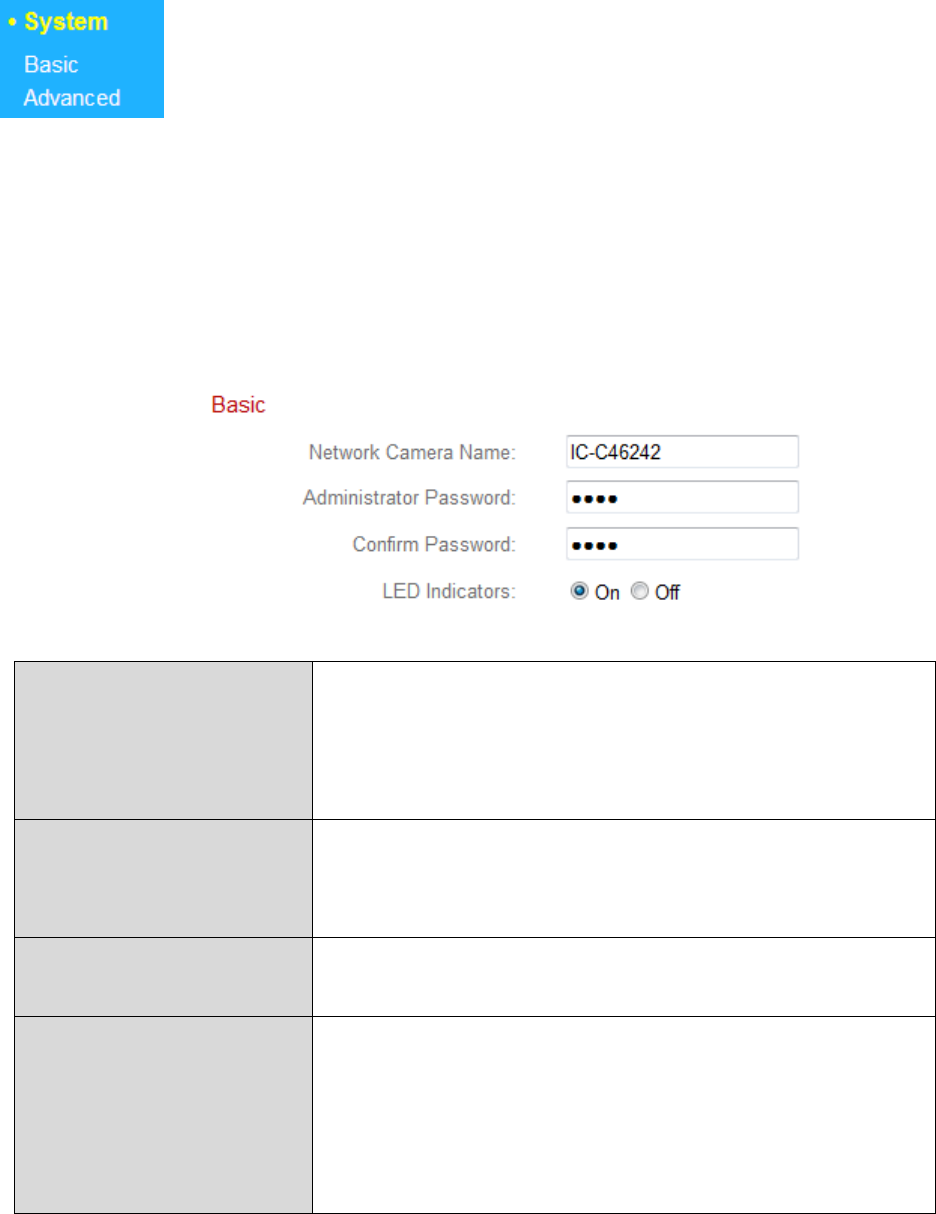
IV-5-1. Basic
The “Basic” menu enables you to set the camera’s name and administrator
password, as well as switch the LED(s) on/off according to your preference.
Network Camera
Name
Set the name of the network camera for
reference/identification purposes. This is
especially useful when managing multiple
network cameras.
Administrator
Password
Enter your desired administrator password
here. This is the password used to log into the
camera with the “admin” account.
Confirm Password
Confirm your desired administrator password
here.
LED Indication
Select “On” or “Off” to switch the network
camera’s LED(s) on or off. Switching off the
LEDs can be a power saving measure or can
be for security purposes, so that anybody
who can see the network camera is unaware
51
if the camera is active.
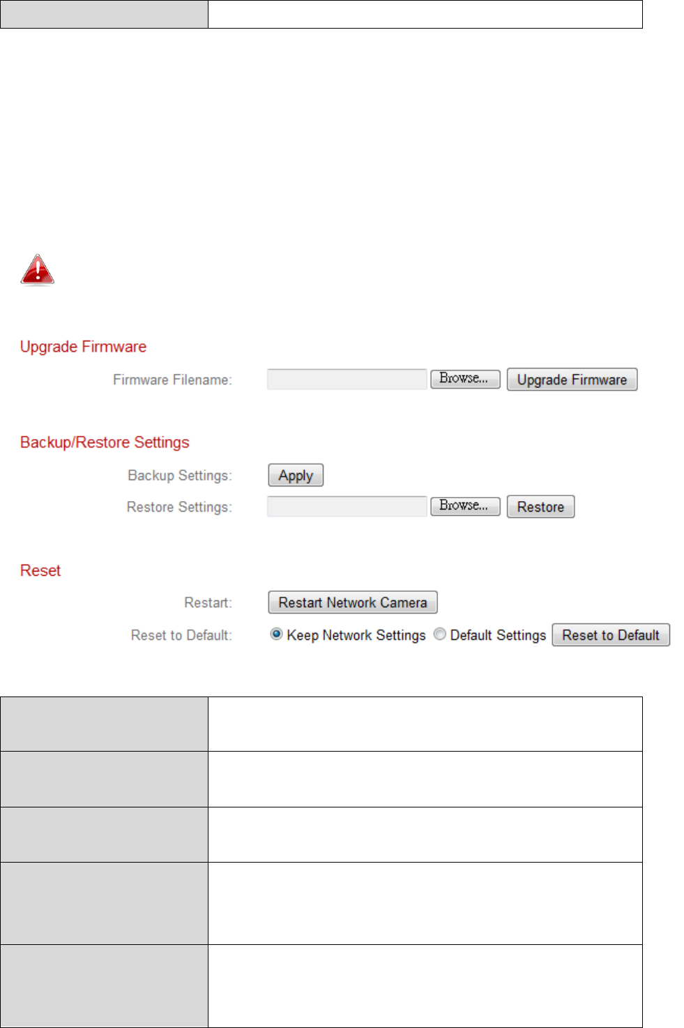
IV-5-2. Advanced
The “Advanced” page allows you to upgrade the network camera’s firmware,
backup or restore the network camera’s settings, and reset or restart the
network camera.
Do not switch off or disconnect the device during a firmware
upgrade, as this could damage the device.
Firmware Filename
Click “Browse” to locate the firmware file on
your computer.
Upgrade Firmware
Click to upgrade the firmware to your
selected file.
Backup Settings
Click “Apply” to save the current settings on
your computer as config.bin file.
Restore Settings
Click “Browse” to find a previously saved
config.bin file and then click “Upload” to
replace your current settings.
Restart
Click “Restart Network Camera” to restart the
network camera. Please wait a couple of
minutes for network camera to boot up after

52
a restart. Restarting will not affect the
camera’s current configuration.
Reset to default
Select “Keep Network Settings” or “Default
Settings” and then click “Reset to Default”.
When the camera resets, “Keep Network
Settings” will reset all settings but keep the
current network settings. The network
camera’s IP address will remain the same.
“Default Settings” will reset all of the
camera’s settings, including network settings,
back to the factory default status.
IV-6. Status
The “Status” menu provides important information about the status of the
network camera. This information is useful for troubleshooting purposes or
for network configuration.
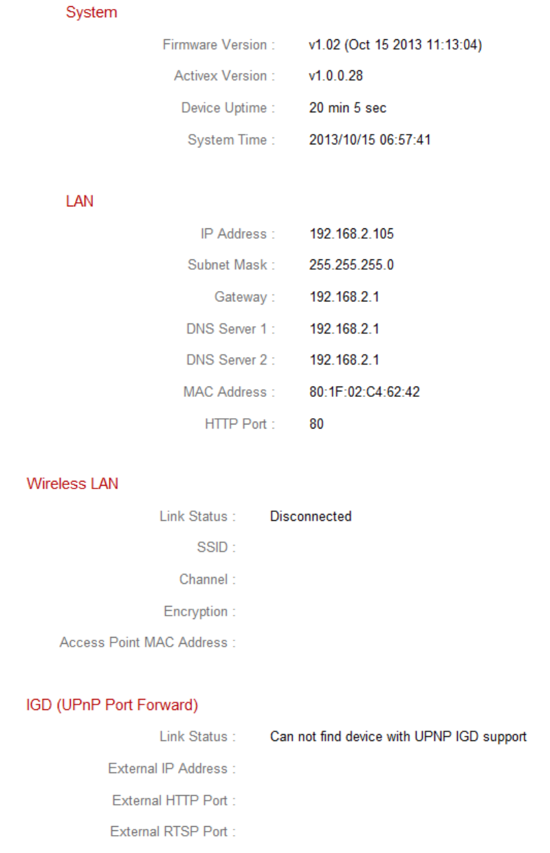
IV-6-1. System Information
A summary of system-wide information about the network camera is
displayed on this page, displayed under four categories: System, LAN, Wireless
LAN and IGD (UPnP Port Forward).
53
54
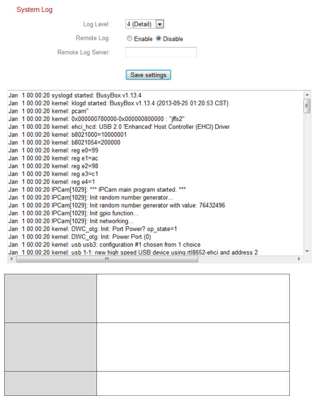
IV-6-2. System Log
A system log provides information about the network camera’s usage and
actions. The system log can also be sent to a remote server for archiving.
Log Level
Select a level of detail for the log from the
dropdown list, from 0 - 4. 0 (minimum) will
only log critical information, while 4
(maximum) will log everything.
Remote Log
Enable or disable the network camera’s
remote log function, to send the log to a
remote server for archiving. The network
camera supports syslog log servers.
Remote Log Server
Enter the IP address or host name of the log
server you wish to use.
55
- End-
Federal Communication Commission Interference Statement
This equipment has been tested and found to comply with the limits for a Class B digital device, pursuant to Part 15 of
the FCC Rules. These limits are designed to provide reasonable protection against harmful interference in a residential
installation. This equipment generates, uses and can radiate radio frequency energy and, if not installed and used in
accordance with the instructions, may cause harmful interference to radio communications. However, there is no
guarantee that interference will not occur in a particular installation. If this equipment does cause harmful interference
to radio or television reception, which can be determined by turning the equipment off and on, the user is encouraged to
try to correct the interference by one or more of the following measures:
Reorient or relocate the receiving antenna.
Increase the separation between the equipment and receiver.
Connect the equipment into an outlet on a circuit different from that to which the receiver is connected.
Consult the dealer or an experienced radio/TV technician for help.
FCC Caution: Any changes or modifications not expressly approved by the party responsible for compliance could void
the user's authority to operate this equipment.
This device complies with Part 15 of the FCC Rules. Operation is subject to the following two conditions: (1) This device
may not cause harmful interference, and (2) this device must accept any interference received, including interference
that may cause undesired operation.
This device and its antenna(s) must not be co-located or operating in conjunction with any other antenna or transmitter.
IMPORTANT NOTE:
FCC Radiation Exposure Statement:
This equipment complies with FCC radiation exposure limits set forth for an uncontrolled environment. This equipment
should be installed and operated with minimum distance 20cm between the radiator & your body.