Edimax Technology Co 9571570411 802.11g WIRELESS LAN MINI-PCI CARD User Manual EW 7157Mg
Edimax Technology Co Ltd 802.11g WIRELESS LAN MINI-PCI CARD EW 7157Mg
UserManual.wiki
>
Edimax Technology Co
>
9571570411 User Manual
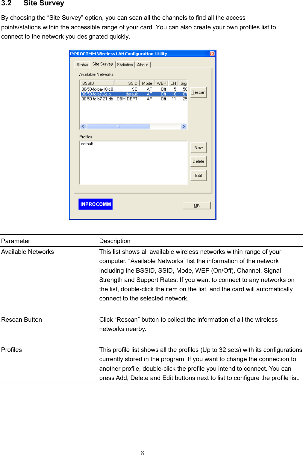
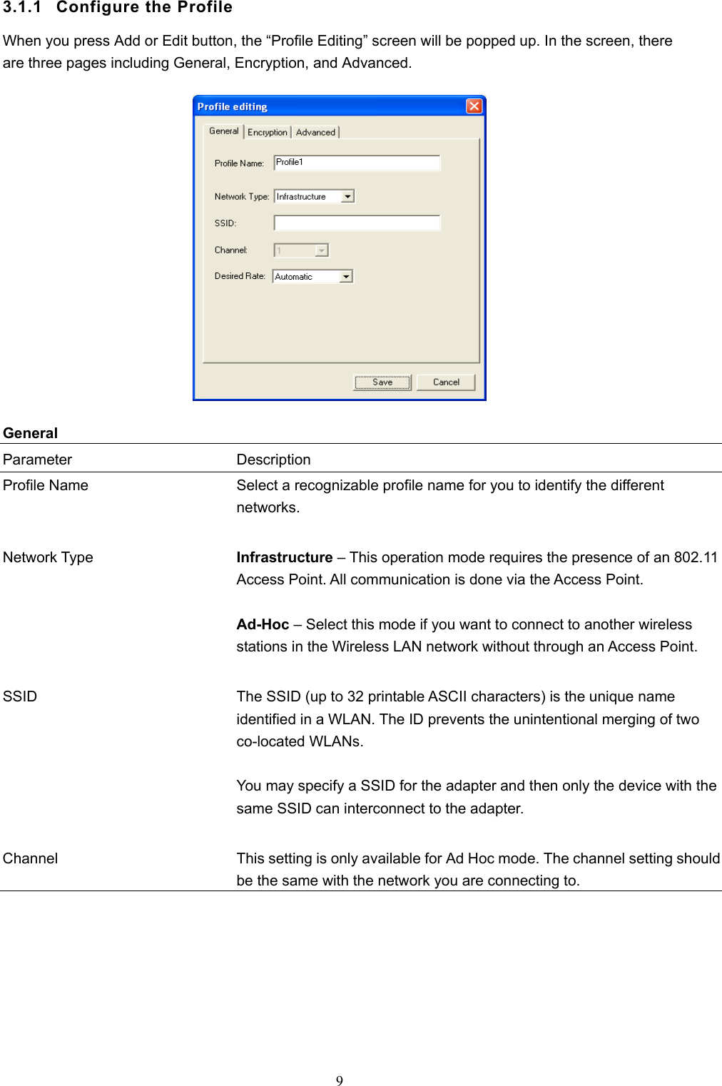
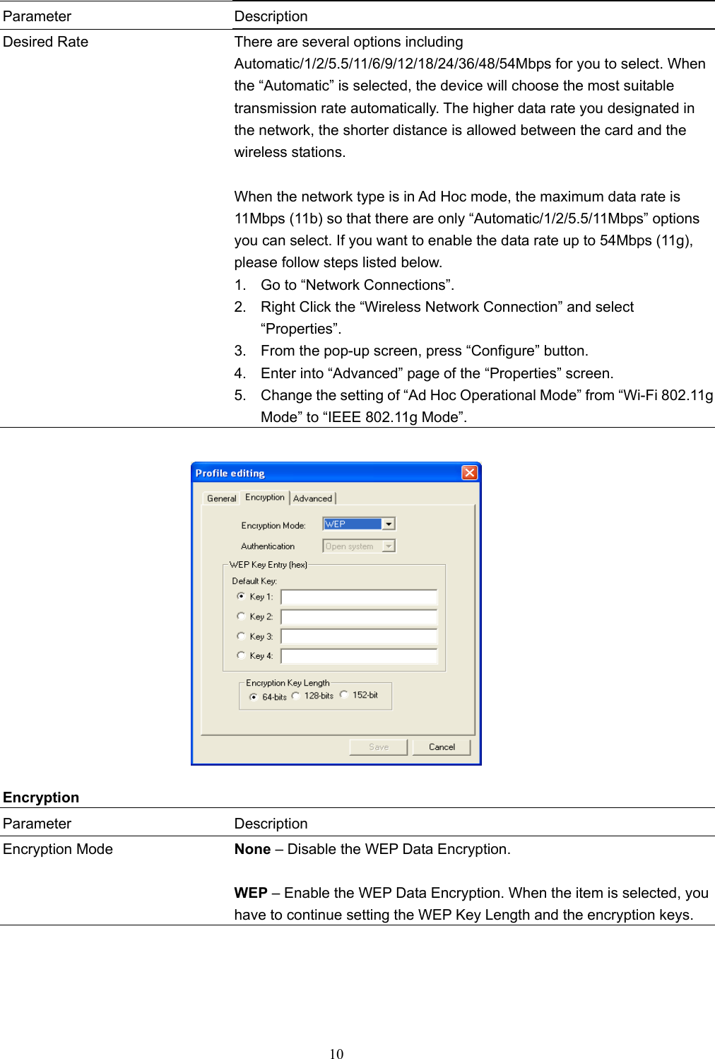
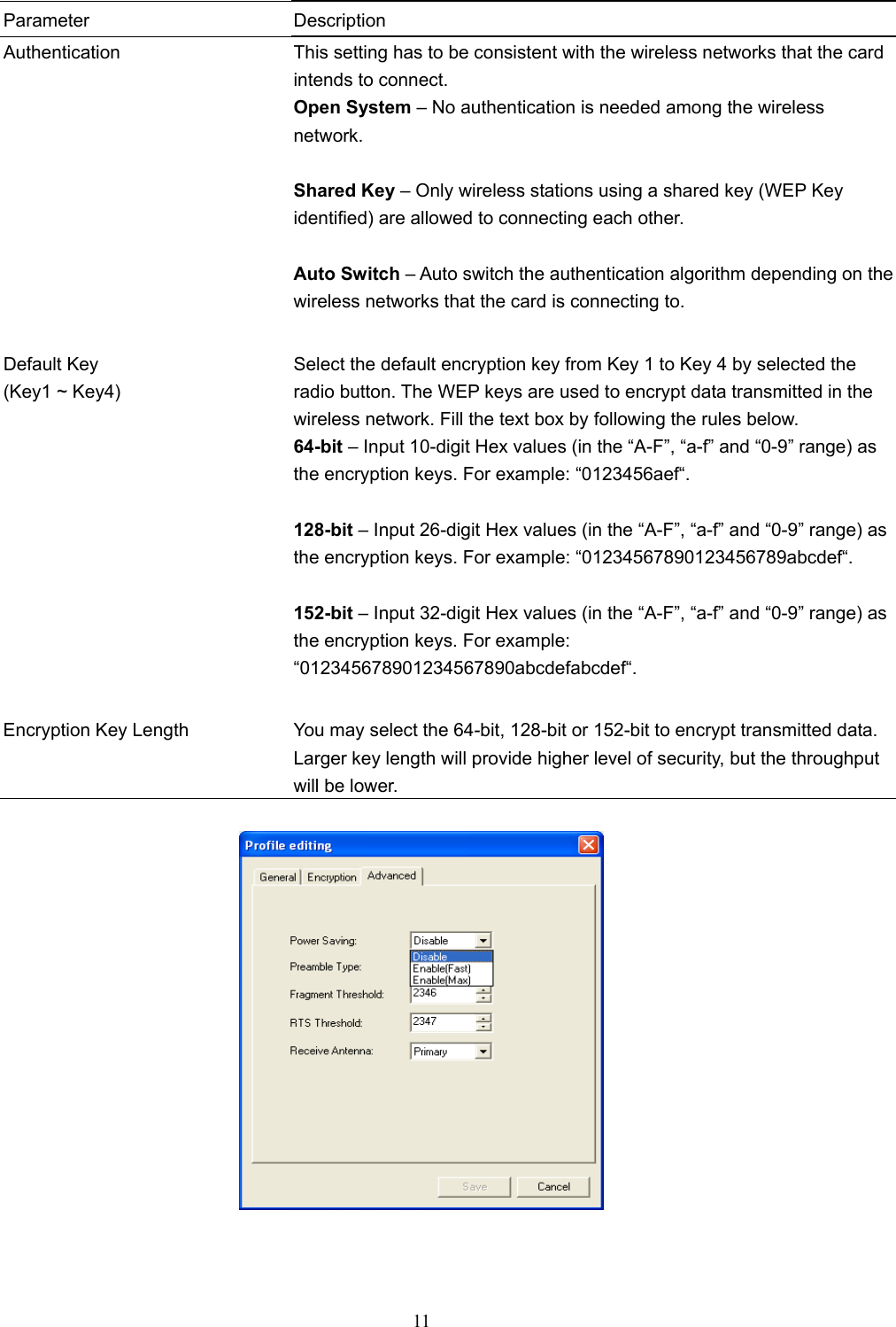
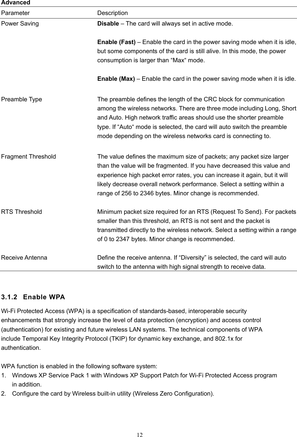
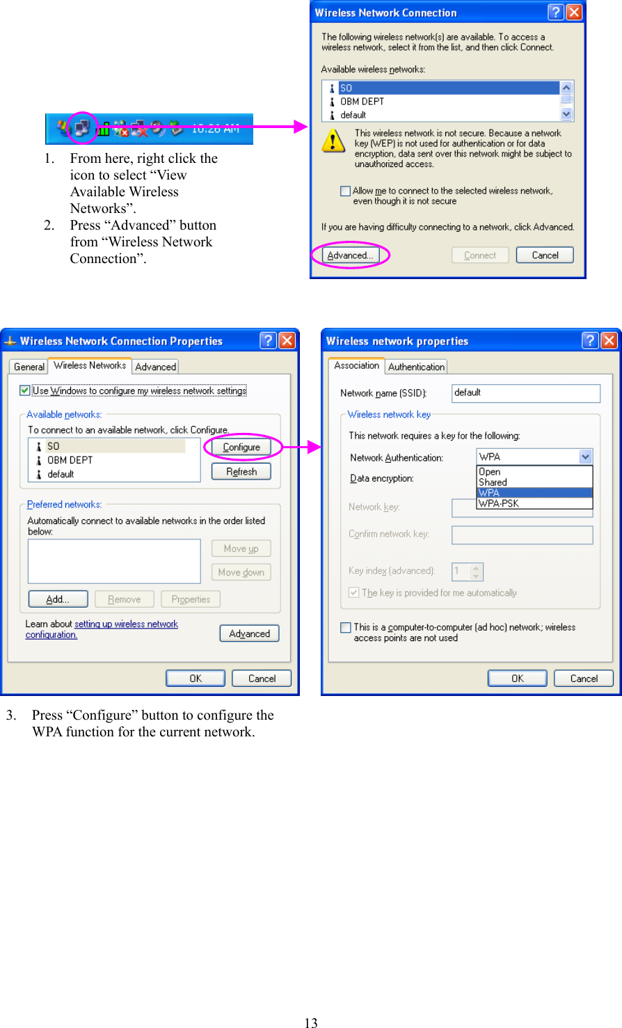
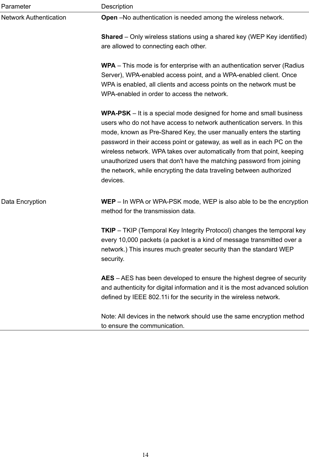
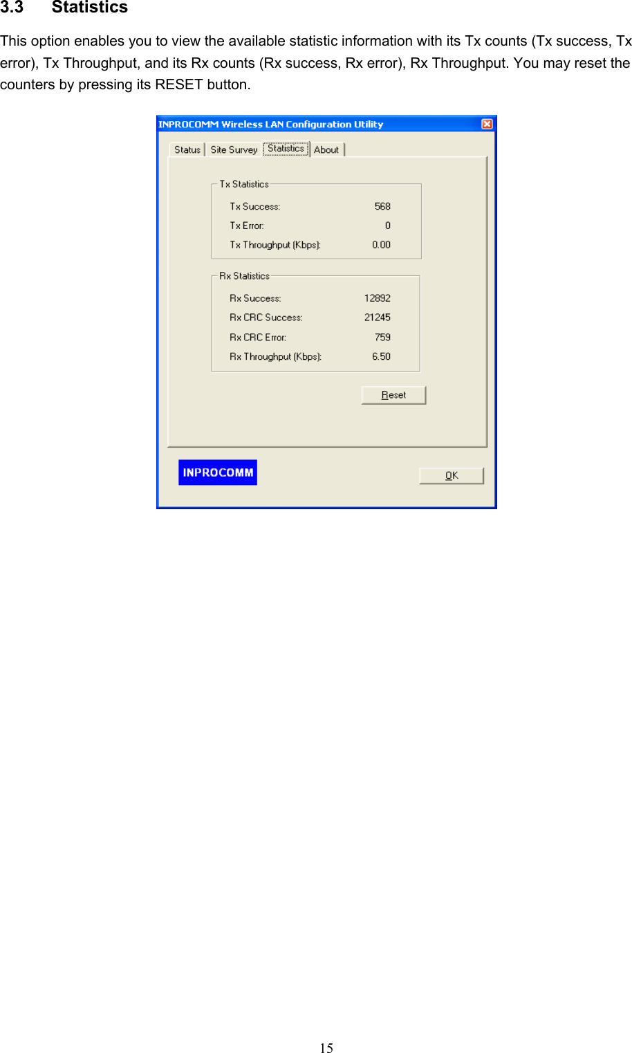
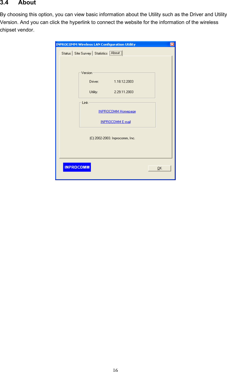
USERS MANUAL
Navigation menu
Upload a User Manual
Namespaces
Wiki Guide
HTML
PDF
Info
Views
User Manual
Discussion / Help
Navigation