Edimax Technology Co 9571570411 802.11g WIRELESS LAN MINI-PCI CARD User Manual EW 7157Mg
Edimax Technology Co Ltd 802.11g WIRELESS LAN MINI-PCI CARD EW 7157Mg
USERS MANUAL
8
80
02
2.
.1
11
1g
g
W
Wi
ir
re
el
le
es
ss
s
L
LA
AN
N
M
Mi
in
ni
i-
-P
PC
CI
I
C
Ca
ar
rd
d
User Manual
Version: 1.0
(January, 2004)
COPYRIGHT
Copyright ©2004/2005 by this company. All rights reserved. No part of this
publication may be reproduced, transmitted, transcribed, stored in a retrieval system,
or translated into any language or computer language, in any form or by any means,
electronic, mechanical, magnetic, optical, chemical, manual or otherwise, without the
prior written permission of this company
This company makes no representations or warranties, either expressed or implied,
with respect to the contents hereof and specifically disclaims any warranties,
merchantability or fitness for any particular purpose. Any software described in this
manual is sold or licensed "as is". Should the programs prove defective following their
purchase, the buyer (and not this company, its distributor, or its dealer) assumes the
entire cost of all necessary servicing, repair, and any incidental or consequential
damages resulting from any defect in the software. Further, this company reserves the
right to revise this publication and to make changes from time to time in the contents
hereof without obligation to notify any person of such revision or changes.
All brand and product names mentioned in this manual are trademarks and/or
registered trademarks of their respective holders.
Federal Communications Commission (FCC) Radiation Exposure
Statement
This device complies with Part 15 of the FCC Rules. Operation is subject to the following
two conditions:(1) this device may not cause harmful interference, and (2) this device
must accept any interference received, including interference that may cause undesired
operation.
This equipment has been tested and found to comply with the limits for a Class B digital
device, pursuant to Part 15 of the FCC Rules. These limits are designed to provide
reasonable protection against harmful interference in a residential installation. This
equipment generates, uses and can radiated radio frequency energy and, if not installed
and used in accordance with the instructions, may cause harmful interference to radio
communications. However, there is no guarantee that interference will not occur in a
particular installation If this equipment does cause harmful interference to radio or
television reception, which can be determined by turning the equipment off and on, the
user is encouraged to try to correct the interference by one or more of the following
measures:
-Reorient or relocate the receiving antenna.
-Increase the separation between the equipment and receiver.
-Connect the equipment into an outlet on a circuit different from that to which the receiver
is connected.
-Consult the dealer or an experienced radio/TV technician for help.
Changes or modifications not expressly approved by the party responsible for
compliance could void the user‘s authority to operate the equipment.
FCC Caution
This device and its antenna(s) used for this transmitter must not be co-located or
operating in conjunction with any other antenna or transmitter.
This equipment complies with FCC radiation exposure limits set forth for an uncontrolled
environment. In order to avoid the possibility of exceeding the FCC radio frequency
exposure limits, human proximity to the antenna shall not be less than 20cm (8 inches)
during normal operation.
If the FCC ID is not visible when the module is installed inside another
device, then the outside of the device into which the module is installed
must also display a label referring to the enclosed module. This exterior
label can use wording such as the following: “Contains Transmitter Module
FCC ID: NDD9571570411” or “Contains FCC ID: NDD9571570411.”
R&TTE Compliance Statement
This equipment complies with all the requirements of DIRECTIVE 1999/5/EC OF THE
EUROPEAN PARLIAMENT AND THE COUNCIL of March 9, 1999 on radio
equipment and telecommunication terminal Equipment and the mutual recognition of
their conformity (R&TTE)
The R&TTE Directive repeals and replaces in the directive 98/13/EEC
(Telecommunications Terminal Equipment and Satellite Earth Station Equipment) As
of April 8, 2000.
Safety
This equipment is designed with the utmost care for the safety of those who install and
use it. However, special attention must be paid to the dangers of electric shock and
static electricity when working with electrical equipment. All guidelines of this and of
the computer manufacture must therefore be allowed at all times to ensure the safe
use of the equipment.
EU Countries Intended for Use
The ETSI version of this device is intended for home and office use in Austria,
Belgium, Denmark, Finland, France, Germany, Greece, Ireland, Italy, Luxembourg,
the Netherlands, Portugal, Spain, Sweden, and the United Kingdom.
The ETSI version of this device is also authorized for use in EFTA member states:
Iceland, Liechtenstein, Norway, and Switzerland.
EU Countries Not intended for use
None.
CONTENTS
1 INTRODUCTION............................................................................. 1
1.1 Features......................................................................................................................... 1
1.2 Specifications................................................................................................................ 1
1.3 Package Contents.......................................................................................................... 2
2 INSTALLATION PROCEDURE ..................................................... 3
3 CONFIGURATION UTILITY ......................................................... 5
3.1 Status............................................................................................................................. 6
3.2 Site Survey.................................................................................................................... 8
3.1.1 Configure the Profile ................................................................................................ 9
3.1.2 Enable WPA ..........................................................................................................12
3.3 Statistics ...................................................................................................................... 15
3.4 About........................................................................................................................... 16
4 TROUBLESHOOTING .................................................................. 17

1
1 Introduction
Thank you for purchasing the 802.11g Wireless LAN Mini-PCI Card. This card complies with IEEE
802.11g standard, which supports up to 54Mbps high-speed wireless network connections. It can also
work with IEEE 802.11b devices. When the card connects to 11b devices, the link speed will be up to
11Mbps.
For WLAN security issues, this card supports 64/128/152-bit WEP data encryption that protects your
wireless network from eavesdropping. It also provides WPA (Wi-Fi Protected Access) feature that
combines IEEE 802.1x and TKIP (Temporal Key Integrity Protocol) technologies. Client users are
required to authorize before accessing to APs or AP Routers, and the data transmitted in the network is
encrypted/decrypted by a secret key dynamically changed. This card has built-in AES engine which
ensure the highest degree of security and authenticity for digital information and it is the most advanced
solution defined by IEEE 802.11i for the security in the wireless network.
The power consumption of the card is also very low. Furthermore, this card provides several levels of
power saving modes allowing user customizes the way of saving the power from his/her portable or
handheld devices.
This card is cost-effective, together with the versatile features; it is the best solution for you to build your
wireless network.
1.1 Features
• Works with both IEEE 802.11b and IEEE 802.11g products.
• High-speed transfer data rate - up to 54Mbps.
• High throughput supports multi-media data bandwidth requirement.
• Supports 64/128/152-bit WEP, WPA (TKIP with IEEE 802.1x) and AES functions for high
level of security.
• Comply with draft of IEEE 802.11e EDCF and HCF polling for multimedia over WLAN
applications.
• Automatic fallback increases data security and reliability.
• Supports the most popular operating system: Windows 98SE/Me/2000/XP.
• Supports Mini-PCI Type III B interface.
1.2 Specifications
• Standard: IEEE 802.11b/g
• Interface: Mini-PCI Type III B
• Frequency Band: 2.4000 ~ 2.4835GHz (Industrial Scientific Medical Band)
• Modulation: OFDM with BPSK, QPSK, 16QAM, 64QAM (11g)
BPSK, QPSK, CCK (11b)
2
• Data Rate: 54/48/36/24/18/12/11/9/6/5.5/2/1Mbps auto fallback
• Security: 64/128/152-bit WEP Data Encryption, WPA, AES and IEEE 802.1x
• Antenna Connector: I-PEX x 2
• Drivers: Windows 98SE/Me/2000/XP
• LEDs: Link/Activity
• Transmit Power: 15dBm~19dBm
• Power consumption: Tx: 370mA, Rx: 310mA
• Receive Sensitivity: 54Mbps OFDM, 10% PER, -72dBm, 11Mbps CCK, 8% PER, -85dBm,
1Mbps BPSK, 8% PER, -93dBm
• Dimension: 59.6(L) x 44.45(W) mm
• Temperature: 32~131°F (0 ~55°C)
• Humidity: Max. 95% (NonCondensing)
• Certification: FCC, CE
1.3 Package Contents
Before you begin the installation, please check the items of your package. The package should include
the following items:
• One Mini-PCI Card
• One CD (Driver/Utility/User’s Manual.)
• One Quick Guide
If any of the above items is missing, contact your supplier as soon as possible.
3
2 Installation Procedure
Before you proceed with the installation, please notice following descriptions.
Note1: Please do not install the card into your laptop computer before installing the software
program from the CD.
Note2: The following installation was operated under Windows XP. (Procedures are similar for
Windows 98SE/Me/2000.)
Note3: If you have installed the Wireless Mini-PCI Card driver & utility before, please uninstall
the old version first.
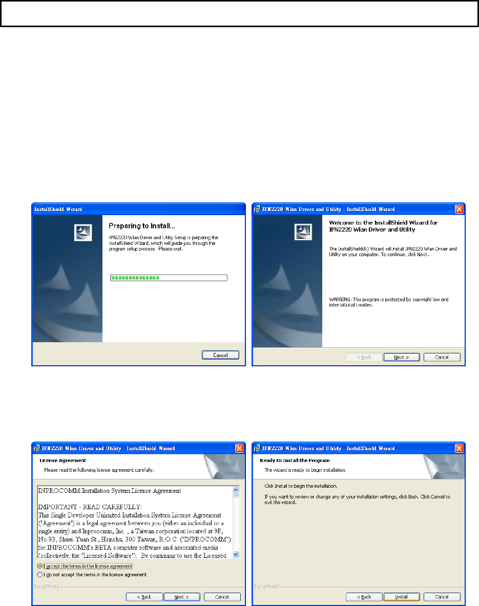
1. Execute the “setup” program located in the “Driver&Utility” folder of CD. Click “Next” button to
continue installation.
2. Review the “License Agreement”. Select “I accept the terms in the license agreement”, then click
“Next” button. Click “Install” button from “Ready to Install the Program” screen, the system will
install the driver and utility of the card automatically.
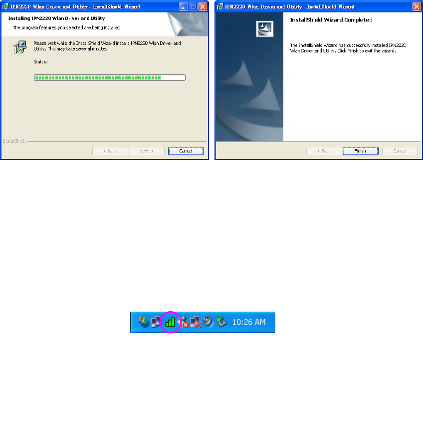
3. Click “Yes” button while the “Digital Signature Not Found” screen popped up. Click “Finish” button
to complete the installation.
4
4. When the installation is done, install the Mini-PCI Card into the Mini-PCI slot of your laptop
computer.
5. The system will automatically detect the card as a new device and display “Found New Hardware
Wizard” dialog box. Follow the installation wizard to complete the device setup step by step.
6. After completing the installation, a new icon will be displayed in the system tray at the bottom of the
screen. Click the icon and start using the WLAN Mini-PCI Card.
5
3 Configuration Utility
The Configuration Utility is a powerful application that helps you configure the Mini-PCI card and
monitor the link status and the statistics during the communication process.
The Wireless LAN Configuration Utility appears as an icon on the system tray of Windows while the
card is running. You can open it by clicking on the icon.
The icon is appeared as bar diagram with different color and level for representing different connection
status. While the station is not associated with other wireless stations or AP, the icon will appear as an
empty (blank) bar diagram. Once it is associated, it will appear as different color for different level of
signal strength. There are 3 levels of icons to represent the signal strength, the green one (signal
strength from 100%-50%), the yellow one (50%-25%), and the red one (below 25%).
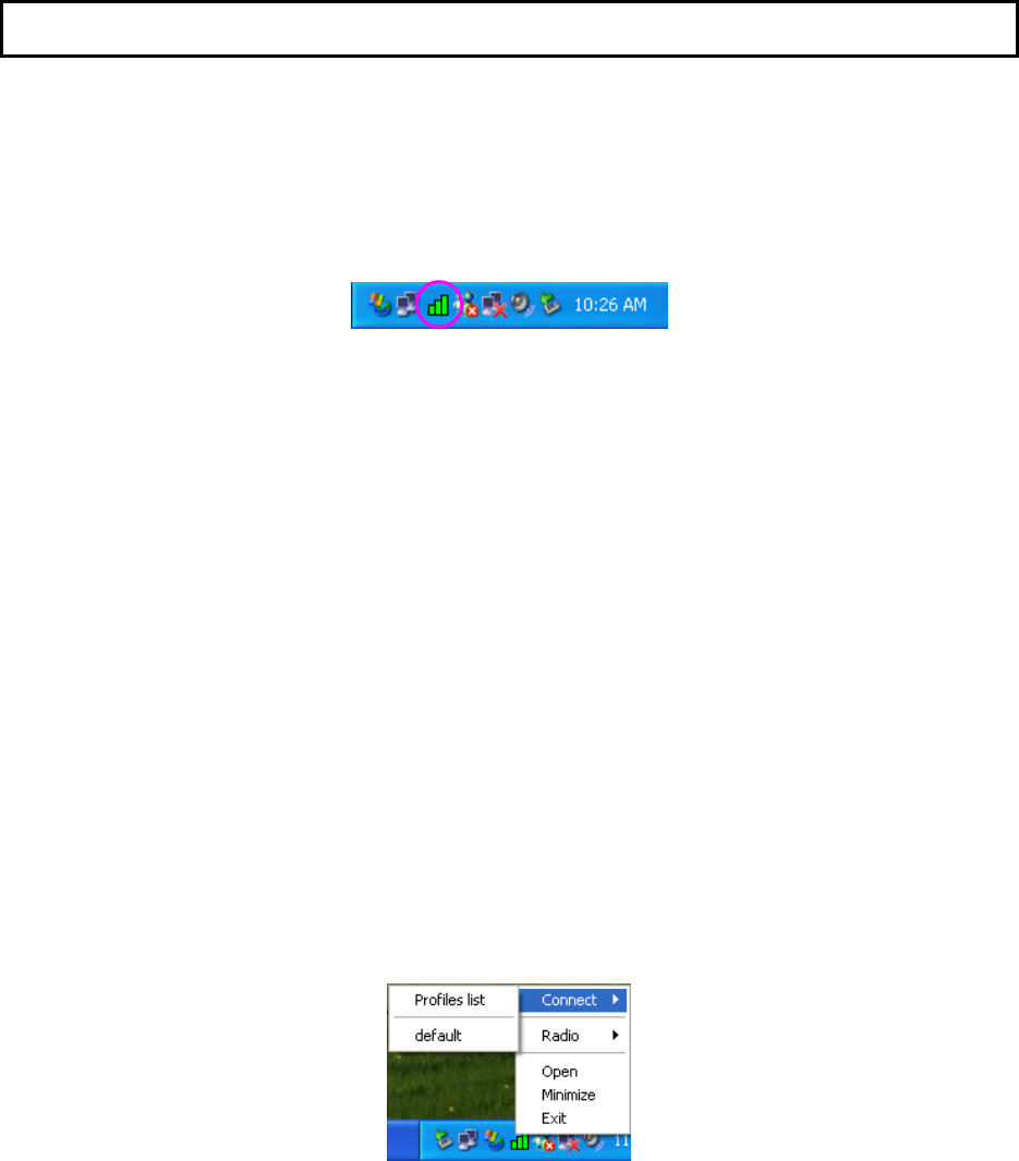
Right click the icon, there are some quick setup items for you to operate the configuration utility.
Connect
A profiles list is shown up, you may review the networks you ever connect to from the list. If you
want to connect to one of the networks immediately, click the network.
Radio
Select “On” to enable the card, select “Off” to disable the card temporarily.
Open
Click “Open” to maximum the screen of the Configuration Utility tool.
Minimize
Click “Minimize” to minimize the screen of the Configuration Utility tool.
Exit
Click “Exit” to close the Configuration Utility tool.
6
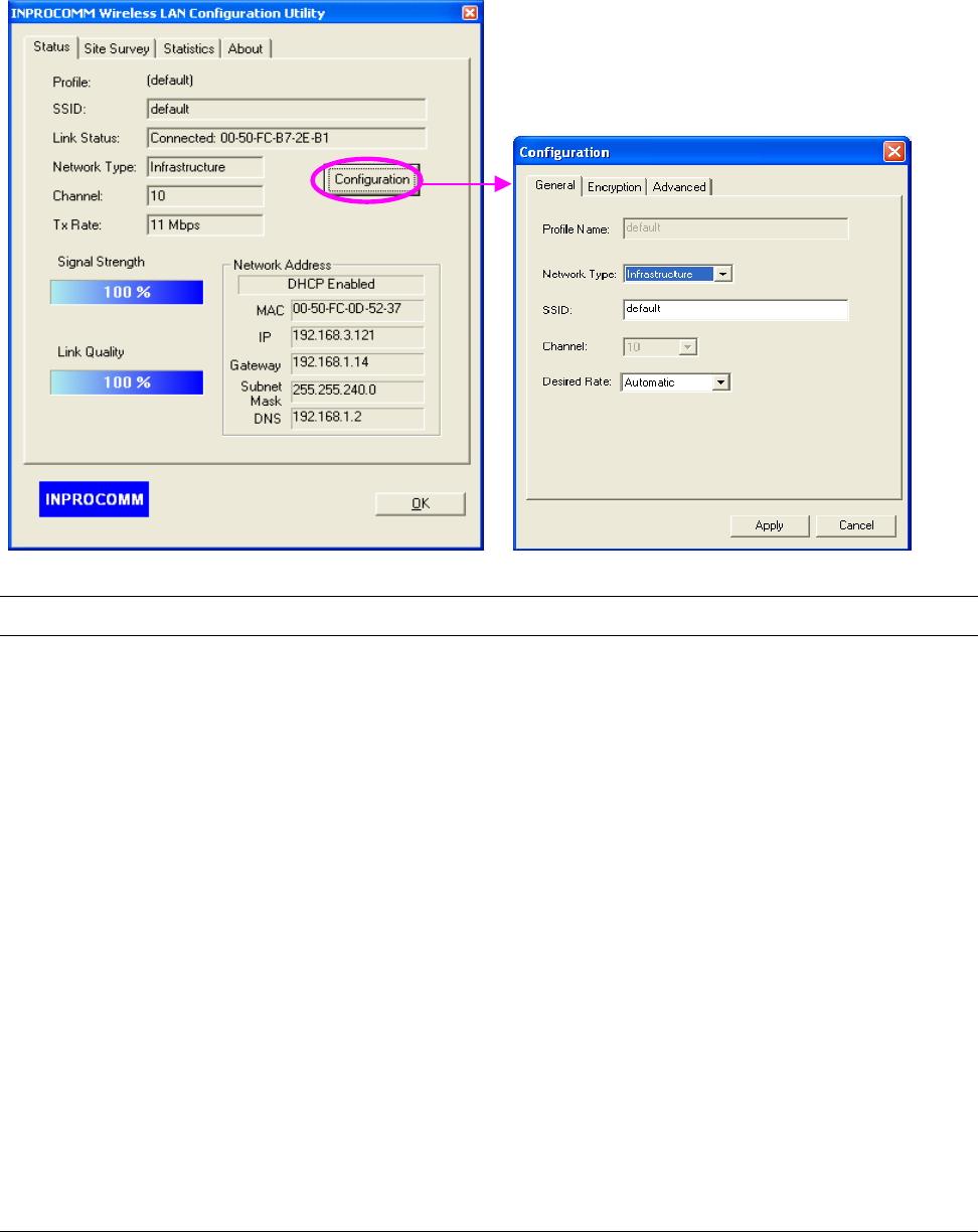
3.1 Status
From the “Status” screen, you can view all the information of the network you are connecting to. To
change the configuration parameters of the network, press the “Configuration” button.
Parameter Description
Profile Display the network the card is connecting to.
SSID The SSID (up to 32 printable ASCII characters) is the unique name
identified in a WLAN. The ID prevents the unintentional merging of two
co-located WLANs.
Only the wireless devices with the same SSID can interconnect.
Link Status Display “Scanning”, “Connected” or “Disconnected” status while the card
is connecting to the network.
Network Type There are two sorts of network types: Infrastructure and Ad Hoc. This
column shows the current network type.
Channel Display the number of the radio channel used for the networking.
Tx Rate From the column, you can know the transmission rate of the network. The
maximum transmission rate is 54Mbps.

7
Parameter Description
Signal Strength This bar shows the signal strength level. The higher percentage shown in
the bar, the more radio signal been received by the card. This indicator
helps to find the proper position of the wireless device for quality network
operation.
Link Quality This bar indicates the quality of the link. The higher the percentage, the
better the quality.
Network Address Network Address section shows the current Network status such as the
MAC address of the card, DHCP (Enable or not), IP address, Gateway
Address, Subnet Mask address, and DNS server address that you can
easily monitor these settings without the “IPCONFIG” provided by
Windows.
Configuration Button Press “Configuration” button to configure the network that the card is
connecting to. Please refer to section 3.2 for detail description.
8
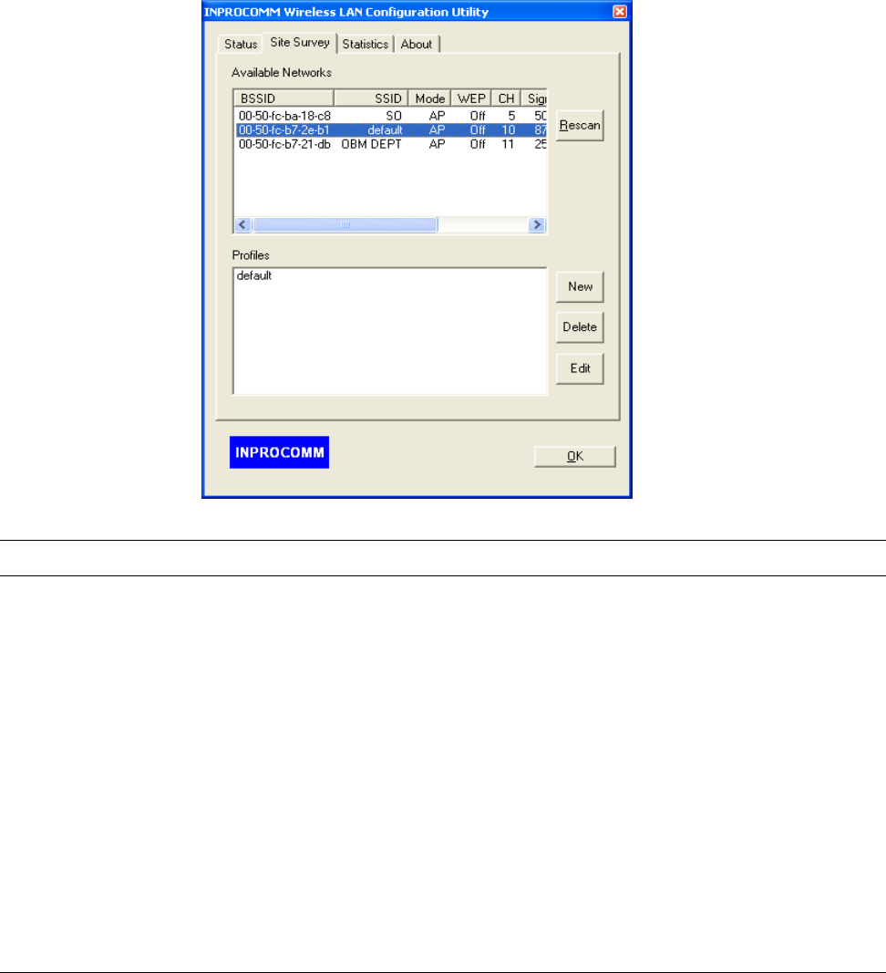
3.2 Site Survey
By choosing the “Site Survey” option, you can scan all the channels to find all the access
points/stations within the accessible range of your card. You can also create your own profiles list to
connect to the network you designated quickly.
Parameter Description
Available Networks This list shows all available wireless networks within range of your
computer. “Available Networks” list the information of the network
including the BSSID, SSID, Mode, WEP (On/Off), Channel, Signal
Strength and Support Rates. If you want to connect to any networks on
the list, double-click the item on the list, and the card will automatically
connect to the selected network.
Rescan Button Click “Rescan” button to collect the information of all the wireless
networks nearby.
Profiles This profile list shows all the profiles (Up to 32 sets) with its configurations
currently stored in the program. If you want to change the connection to
another profile, double-click the profile you intend to connect. You can
press Add, Delete and Edit buttons next to list to configure the profile list.
9
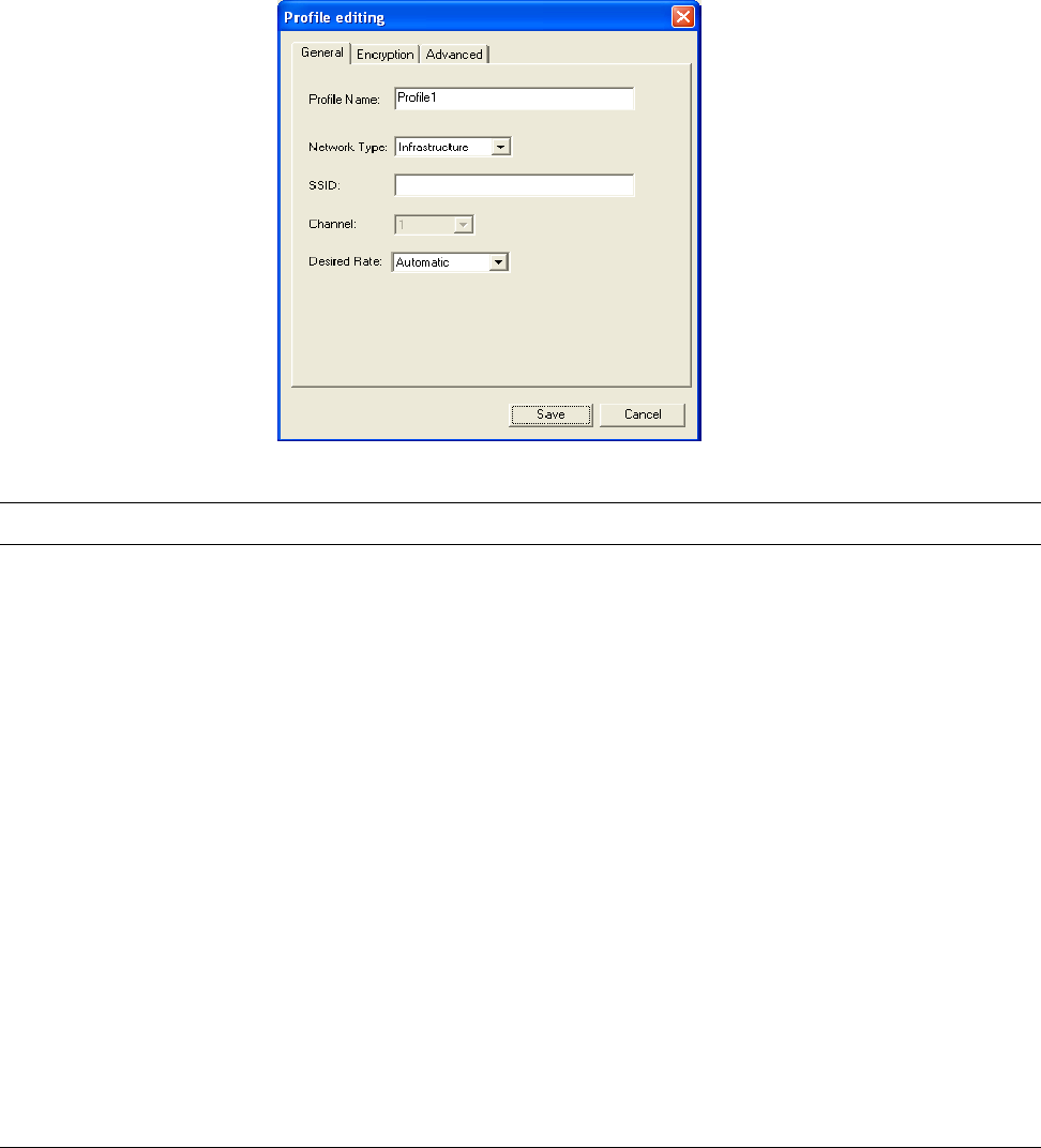
3.1.1 Configure the Profile
When you press Add or Edit button, the “Profile Editing” screen will be popped up. In the screen, there
are three pages including General, Encryption, and Advanced.
General
Parameter Description
Profile Name Select a recognizable profile name for you to identify the different
networks.
Network Type Infrastructure – This operation mode requires the presence of an 802.11
Access Point. All communication is done via the Access Point.
Ad-Hoc – Select this mode if you want to connect to another wireless
stations in the Wireless LAN network without through an Access Point.
SSID The SSID (up to 32 printable ASCII characters) is the unique name
identified in a WLAN. The ID prevents the unintentional merging of two
co-located WLANs.
You may specify a SSID for the adapter and then only the device with the
same SSID can interconnect to the adapter.
Channel This setting is only available for Ad Hoc mode. The channel setting should
be the same with the network you are connecting to.
10
Parameter Description
Desired Rate There are several options including
Automatic/1/2/5.5/11/6/9/12/18/24/36/48/54Mbps for you to select. When
the “Automatic” is selected, the device will choose the most suitable
transmission rate automatically. The higher data rate you designated in
the network, the shorter distance is allowed between the card and the
wireless stations.
When the network type is in Ad Hoc mode, the maximum data rate is
11Mbps (11b) so that there are only “Automatic/1/2/5.5/11Mbps” options
you can select. If you want to enable the data rate up to 54Mbps (11g),
please follow steps listed below.
1. Go to “Network Connections”.
2. Right Click the “Wireless Network Connection” and select
“Properties”.
3. From the pop-up screen, press “Configure” button.
4. Enter into “Advanced” page of the “Properties” screen.
5. Change the setting of “Ad Hoc Operational Mode” from “Wi-Fi 802.11g
Mode” to “IEEE 802.11g Mode”.
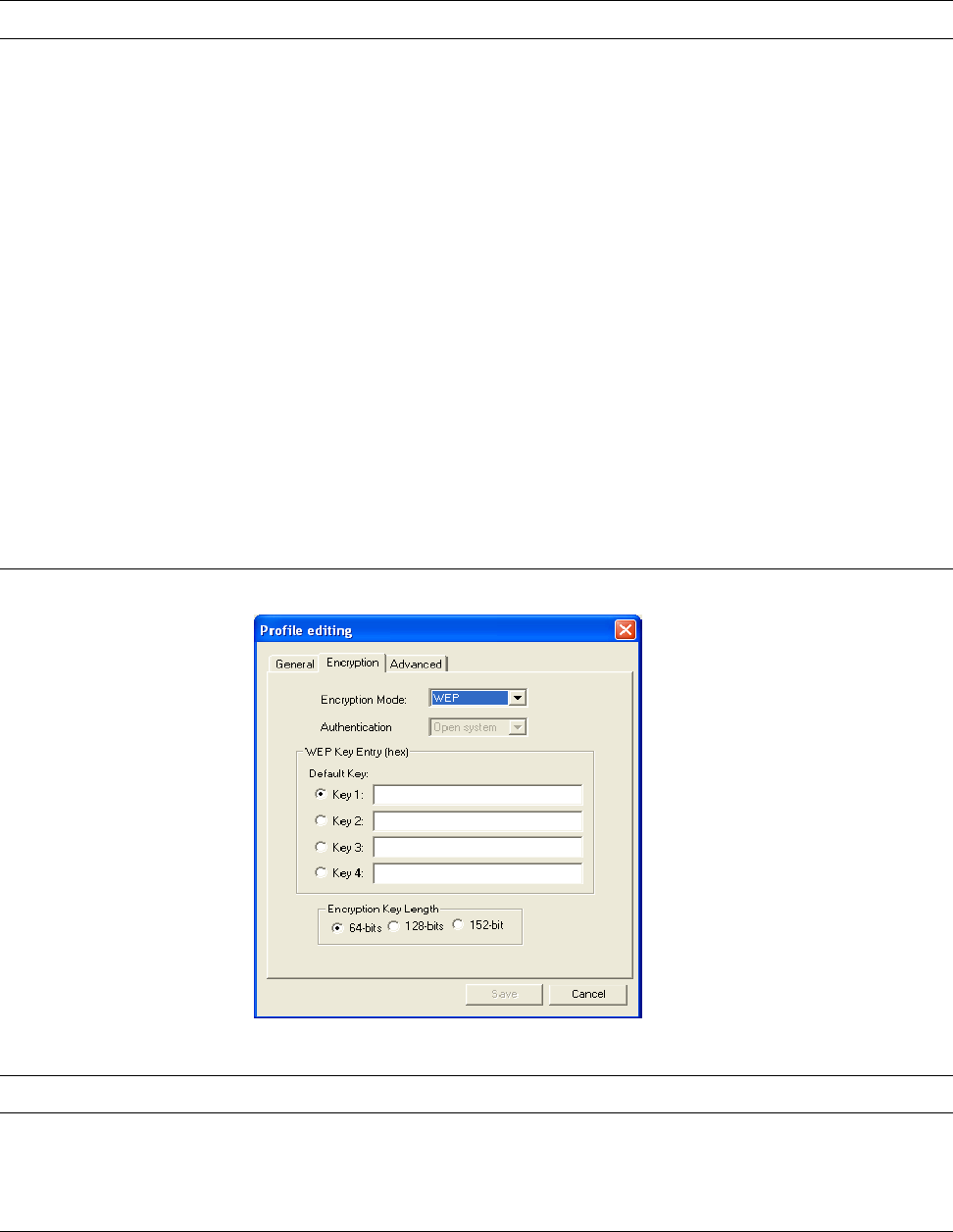
Encryption
Parameter Description
Encryption Mode None – Disable the WEP Data Encryption.
WEP – Enable the WEP Data Encryption. When the item is selected, you
have to continue setting the WEP Key Length and the encryption keys.
11
Parameter Description
Authentication This setting has to be consistent with the wireless networks that the card
intends to connect.
Open System – No authentication is needed among the wireless
network.
Shared Key – Only wireless stations using a shared key (WEP Key
identified) are allowed to connecting each other.
Auto Switch – Auto switch the authentication algorithm depending on the
wireless networks that the card is connecting to.
Default Key
(Key1 ~ Key4)
Select the default encryption key from Key 1 to Key 4 by selected the
radio button. The WEP keys are used to encrypt data transmitted in the
wireless network. Fill the text box by following the rules below.
64-bit – Input 10-digit Hex values (in the “A-F”, “a-f” and “0-9” range) as
the encryption keys. For example: “0123456aef“.
128-bit – Input 26-digit Hex values (in the “A-F”, “a-f” and “0-9” range) as
the encryption keys. For example: “01234567890123456789abcdef“.
152-bit – Input 32-digit Hex values (in the “A-F”, “a-f” and “0-9” range) as
the encryption keys. For example:
“012345678901234567890abcdefabcdef“.
Encryption Key Length You may select the 64-bit, 128-bit or 152-bit to encrypt transmitted data.
Larger key length will provide higher level of security, but the throughput
will be lower.

12
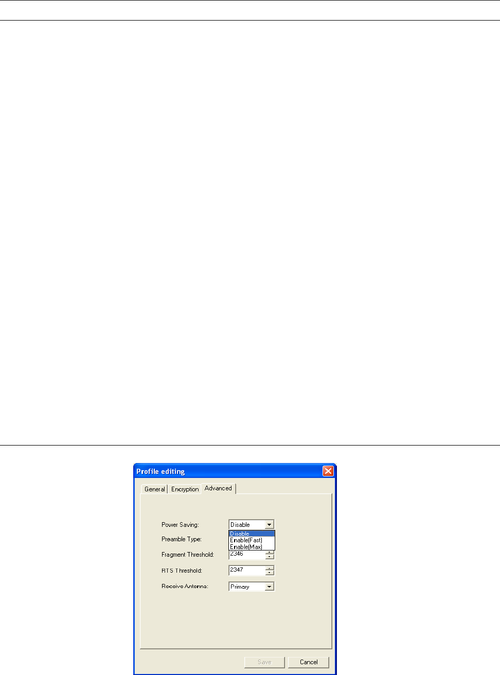
Advanced
Parameter Description
Power Saving Disable – The card will always set in active mode.
Enable (Fast) – Enable the card in the power saving mode when it is idle,
but some components of the card is still alive. In this mode, the power
consumption is larger than “Max“ mode.
Enable (Max) – Enable the card in the power saving mode when it is idle.
Preamble Type The preamble defines the length of the CRC block for communication
among the wireless networks. There are three mode including Long, Short
and Auto. High network traffic areas should use the shorter preamble
type. If “Auto“ mode is selected, the card will auto switch the preamble
mode depending on the wireless networks card is connecting to.
Fragment Threshold The value defines the maximum size of packets; any packet size larger
than the value will be fragmented. If you have decreased this value and
experience high packet error rates, you can increase it again, but it will
likely decrease overall network performance. Select a setting within a
range of 256 to 2346 bytes. Minor change is recommended.
RTS Threshold Minimum packet size required for an RTS (Request To Send). For packets
smaller than this threshold, an RTS is not sent and the packet is
transmitted directly to the wireless network. Select a setting within a range
of 0 to 2347 bytes. Minor change is recommended.
Receive Antenna Define the receive antenna. If “Diversity” is selected, the card will auto
switch to the antenna with high signal strength to receive data.
3.1.2 Enable WPA
Wi-Fi Protected Access (WPA) is a specification of standards-based, interoperable security
enhancements that strongly increase the level of data protection (encryption) and access control
(authentication) for existing and future wireless LAN systems. The technical components of WPA
include Temporal Key Integrity Protocol (TKIP) for dynamic key exchange, and 802.1x for
authentication.
WPA function is enabled in the following software system:
1. Windows XP Service Pack 1 with Windows XP Support Patch for Wi-Fi Protected Access program
in addition.
2. Configure the card by Wireless built-in utility (Wireless Zero Configuration).
13
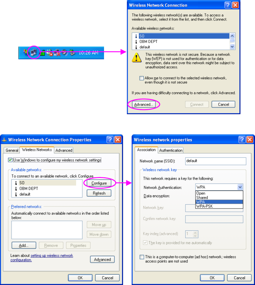
3. Press “Configure” button to configure the
WPA function for the current network.
1. From here, right click the
icon to select “View
Available Wireless
Networks”.
2. Press “Advanced” button
from “Wireless Network
Connection”.

14
Parameter Description
Network Authentication Open –No authentication is needed among the wireless network.
Shared – Only wireless stations using a shared key (WEP Key identified)
are allowed to connecting each other.
WPA – This mode is for enterprise with an authentication server (Radius
Server), WPA-enabled access point, and a WPA-enabled client. Once
WPA is enabled, all clients and access points on the network must be
WPA-enabled in order to access the network.
WPA-PSK – It is a special mode designed for home and small business
users who do not have access to network authentication servers. In this
mode, known as Pre-Shared Key, the user manually enters the starting
password in their access point or gateway, as well as in each PC on the
wireless network. WPA takes over automatically from that point, keeping
unauthorized users that don't have the matching password from joining
the network, while encrypting the data traveling between authorized
devices.
Data Encryption WEP – In WPA or WPA-PSK mode, WEP is also able to be the encryption
method for the transmission data.
TKIP – TKIP (Temporal Key Integrity Protocol) changes the temporal key
every 10,000 packets (a packet is a kind of message transmitted over a
network.) This insures much greater security than the standard WEP
security.
AES – AES has been developed to ensure the highest degree of security
and authenticity for digital information and it is the most advanced solution
defined by IEEE 802.11i for the security in the wireless network.
Note: All devices in the network should use the same encryption method
to ensure the communication.
15
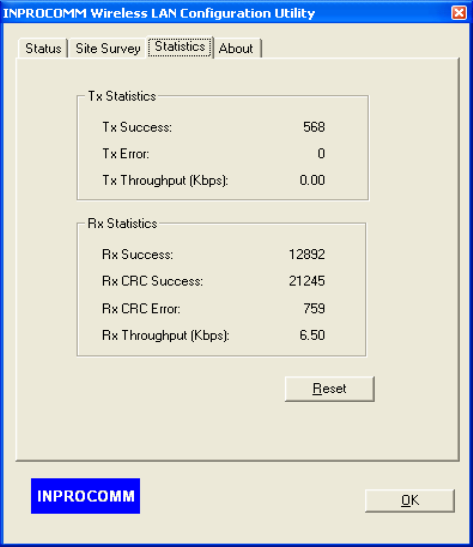
3.3 Statistics
This option enables you to view the available statistic information with its Tx counts (Tx success, Tx
error), Tx Throughput, and its Rx counts (Rx success, Rx error), Rx Throughput. You may reset the
counters by pressing its RESET button.
16
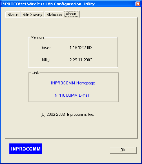
3.4 About
By choosing this option, you can view basic information about the Utility such as the Driver and Utility
Version. And you can click the hyperlink to connect the website for the information of the wireless
chipset vendor.

17
4 Troubleshooting
This chapter provides solutions to problems usually encountered during the installation and operation
of the adapter.
1. What is the IEEE 802.11g standard?
802.11g is the new IEEE standard for high-speed wireless LAN communications that provides for
up to 54 Mbps data rate in the 2.4 GHz band. 802.11g is quickly becoming the next mainstream
wireless LAN technology for the home, office and public networks.
802.11g defines the use of the same OFDM modulation technique specified in IEEE 802.11a for
the 5 GHz frequency band and applies it in the same 2.4 GHz frequency band as IEEE 802.11b.
The 802.11g standard requires backward compatibility with 802.11b.
The standard specifically calls for:
A. A new physical layer for the 802.11 Medium Access Control (MAC) in the 2.4 GHz frequency
band, known as the extended rate PHY (ERP). The ERP adds OFDM as a mandatory new
coding scheme for 6, 12 and 24 Mbps (mandatory speeds), and 18, 36, 48 and 54 Mbps
(optional speeds). The ERP includes the modulation schemes found in 802.11b including
CCK for 11 and 5.5 Mbps and Barker code modulation for 2 and 1 Mbps.
B. A protection mechanism called RTS/CTS that governs how 802.11g devices and 802.11b
devices interoperate.
2. What is the IEEE 802.11b standard?
The IEEE 802.11b Wireless LAN standard subcommittee, which formulates the standard for the
industry. The objective is to enable wireless LAN hardware from different manufactures to
communicate.
3. What does IEEE 802.11 feature support?
The product supports the following IEEE 802.11 functions:
CSMA/CA plus Acknowledge Protocol
Multi-Channel Roaming
Automatic Rate Selection
RTS/CTS Feature
Fragmentation
Power Management
4. What is Ad-hoc?
An Ad-hoc integrated wireless LAN is a group of computers, each has a Wireless LAN adapter,
Connected as an independent wireless LAN. Ad hoc wireless LAN is applicable at a
departmental scale for a branch or SOHO operation.
5. What is Infrastructure?
An integrated wireless and wireless and wired LAN is called an Infrastructure configuration.
Infrastructure is applicable to enterprise scale for wireless access to central database, or
wireless application for mobile workers.
18
6. What is BSS ID?
A specific Ad hoc LAN is called a Basic Service Set (BSS). Computers in a BSS must be
configured with the same BSS ID.
7. What is WEP?
WEP is Wired Equivalent Privacy, a data privacy mechanism based on a 40 bit shared key
algorithm, as described in the IEEE 802 .11 standard.
8. What is TKIP?
TKIP is a quick-fix method to quickly overcome the inherent weaknesses in WEP security,
especially the reuse of encryption keys. TKIP is involved in the IEEE 802.11i WLAN security
standard, and the specification might be officially released by early 2003.
9. What is AES?
AES (Advanced Encryption Standard), a chip-based security, has been developed to ensure the
highest degree of security and authenticity for digital information, wherever and however
communicated or stored, while making more efficient use of hardware and/or software than
previous encryption standards. It is also included in IEEE 802.11i standard. Compare with AES,
TKIP is a temporary protocol for replacing WEP security until manufacturers implement AES at
the hardware level.
10. Can Wireless products support printer sharing?
Wireless products perform the same function as LAN products. Therefore, Wireless products can
work with Netware, Windows 2000, or other LAN operating systems to support printer or file
sharing.
11. Would the information be intercepted while transmitting on air?
WLAN features two-fold protection in security. On the hardware side, as with Direct Sequence
Spread Spectrum technology, it has the inherent security feature of scrambling. On the software
side, WLAN series offer the encryption function (WEP) to enhance security and Access Control.
Users can set it up depending upon their needs.
12. What is DSSS?What is FHSS?And what are their differences?
Frequency-hopping spread-spectrum (FHSS) uses a narrowband carrier that changes frequency
in a pattern that is known to both transmitter and receiver. Properly synchronized, the net effect
is to maintain a single logical channel. To an unintended receiver, FHSS appears to be
short-duration impulse noise. Direct-sequence spread-spectrum (DSSS) generates a redundant
bit pattern for each bit to be transmitted. This bit pattern is called a chip (or chipping code). The
longer the chip is, the greater the probability that the original data can be recovered. Even if one
or more bits in the chip are damaged during transmission, statistical techniques embedded in the
radio can recover the original data without-the need for retransmission. To an unintended
receiver, DSSS appears as low power wideband noise and is rejected (ignored) by most
narrowband receivers.
19
13. What is Spread Spectrum?
Spread Spectrum technology is a wideband radio frequency technique developed by the military
for use in reliable, secure, mission-critical communication systems. It is designed to trade off
bandwidth efficiency for reliability, integrity, and security. In other words, more bandwidth is
consumed than in the case of narrowband transmission, but the trade off produces a signal that
is, in effect, louder and thus easier to detect, provided that the receiver knows the parameters of
the spread-spectrum signal being broadcast. If a receiver is not tuned to the right frequency, a
spread –spectrum signal looks like background noise. There are two main alternatives, Direct
Sequence Spread Spectrum (DSSS) and Frequency Hopping Spread Spectrum (FHSS).