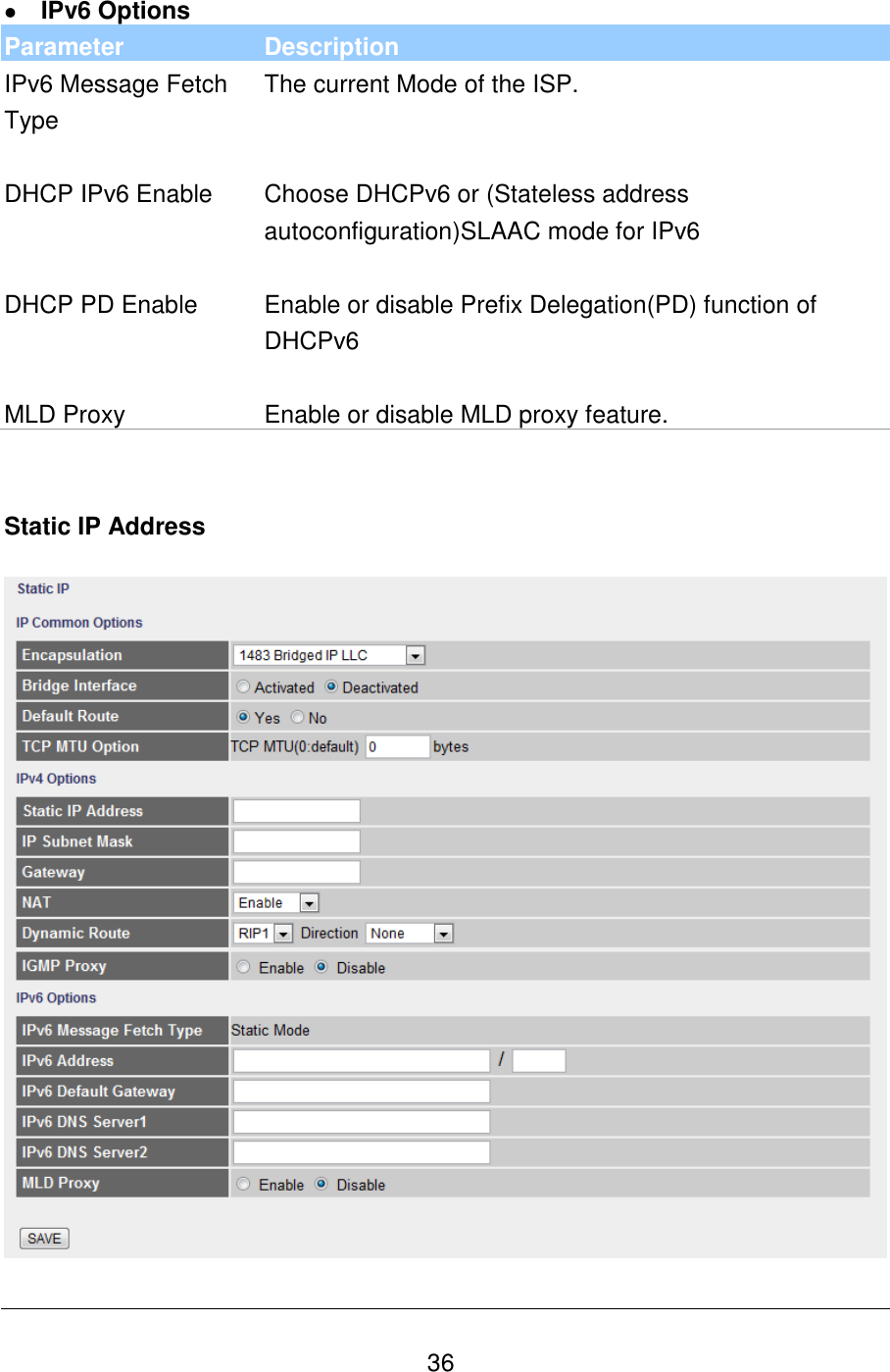
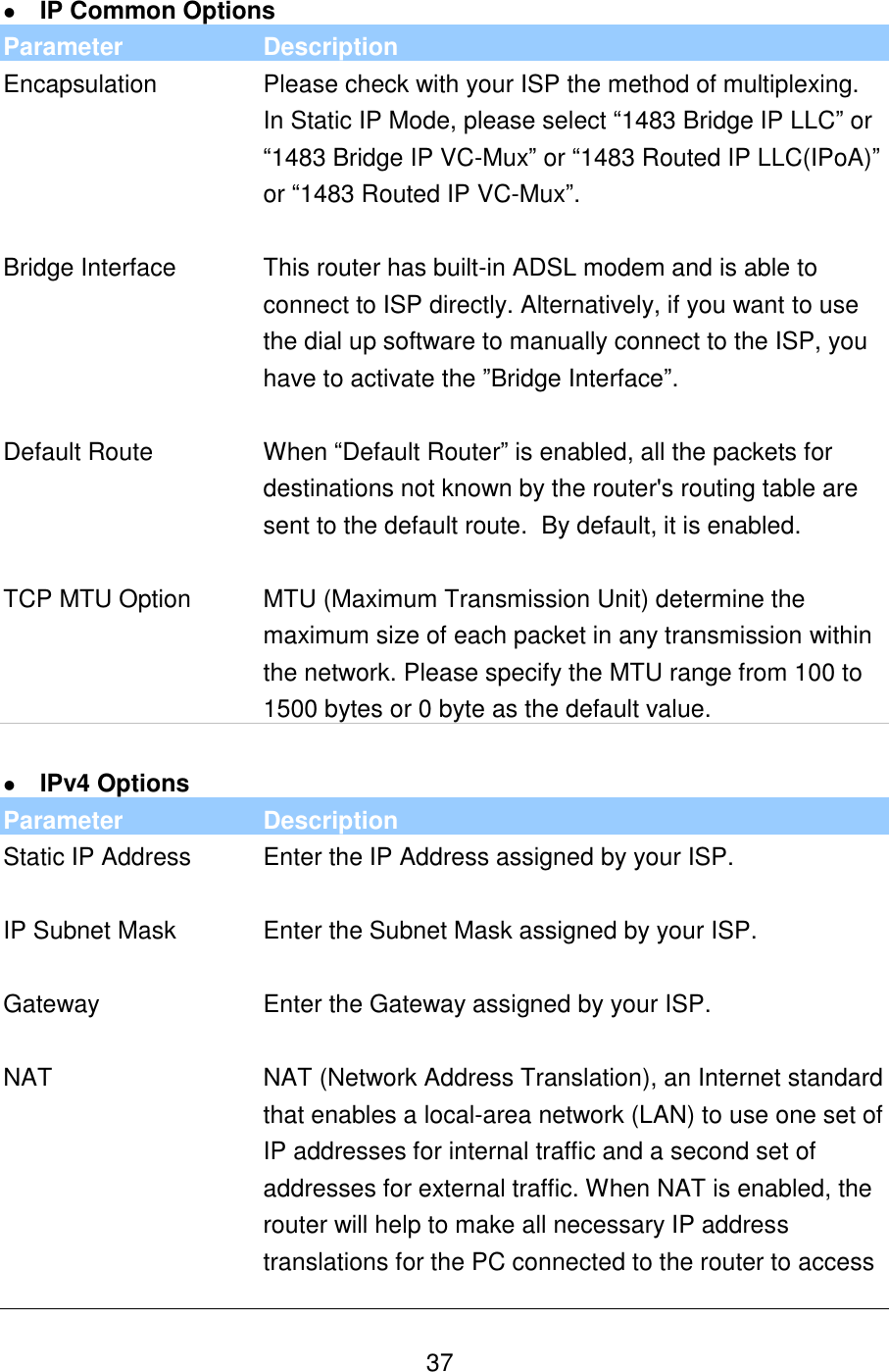
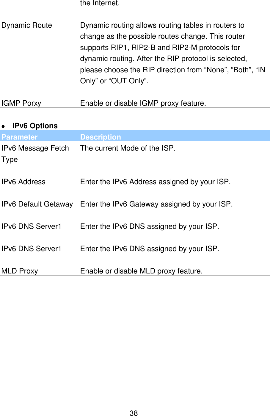
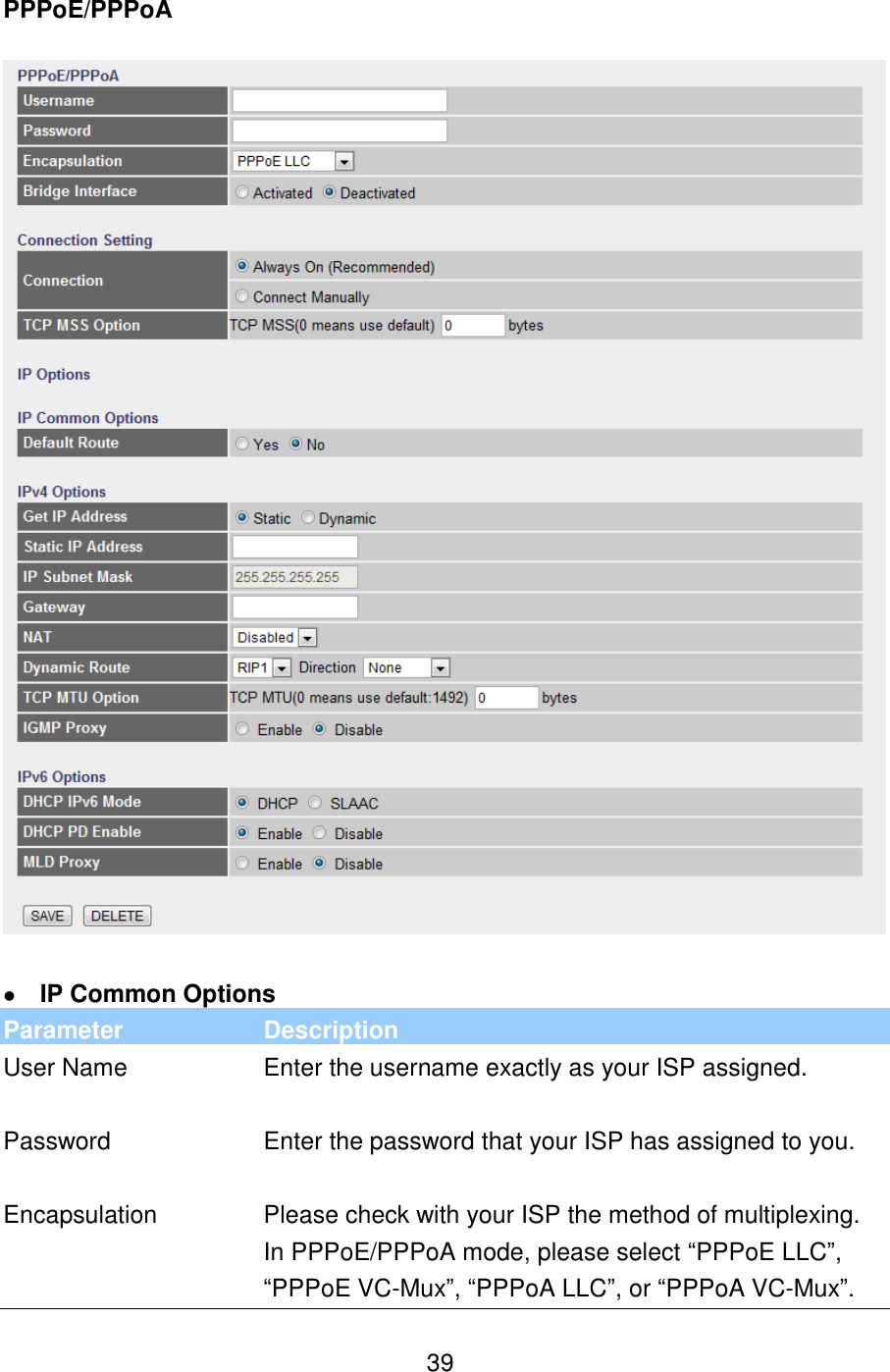
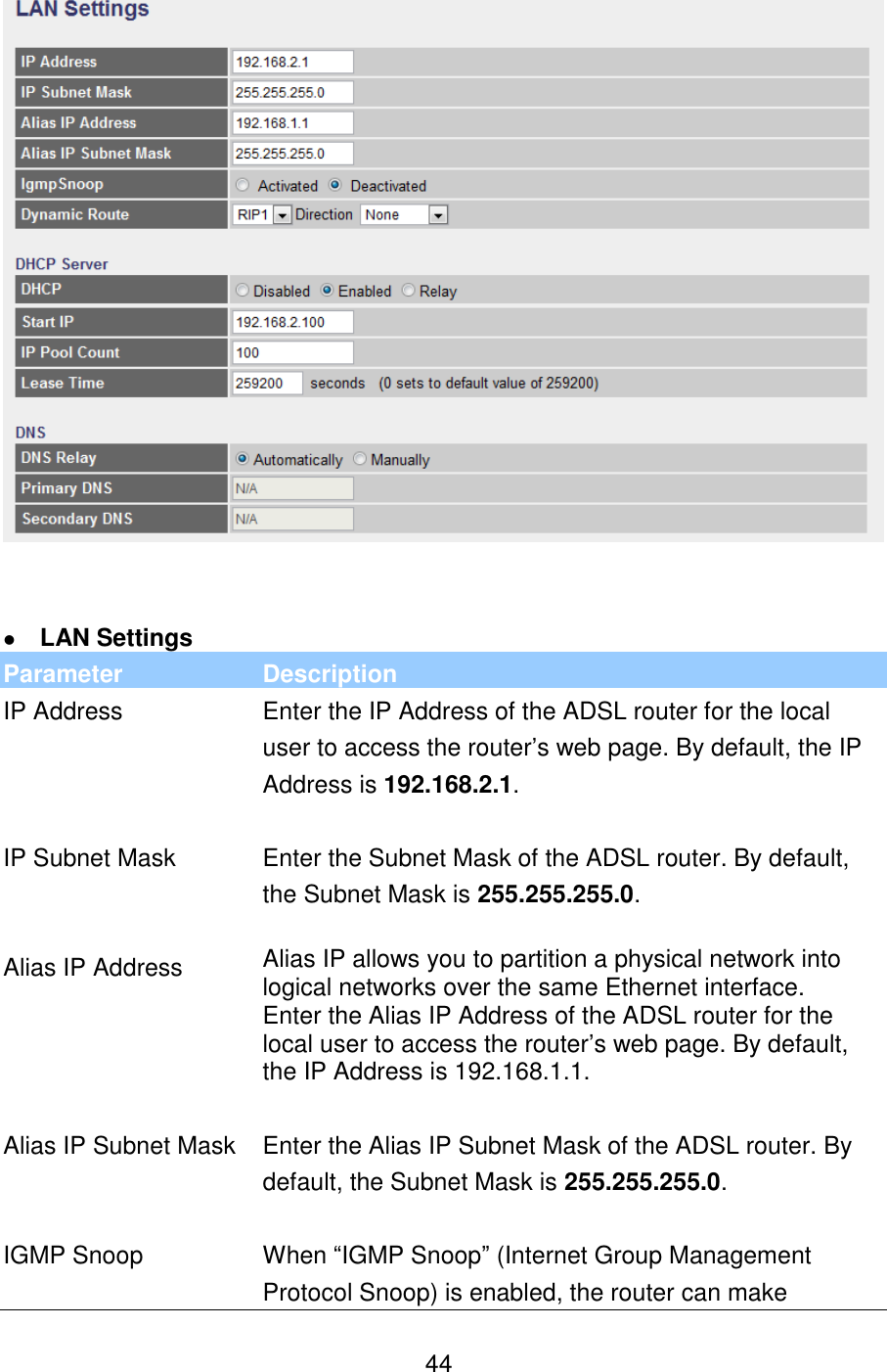
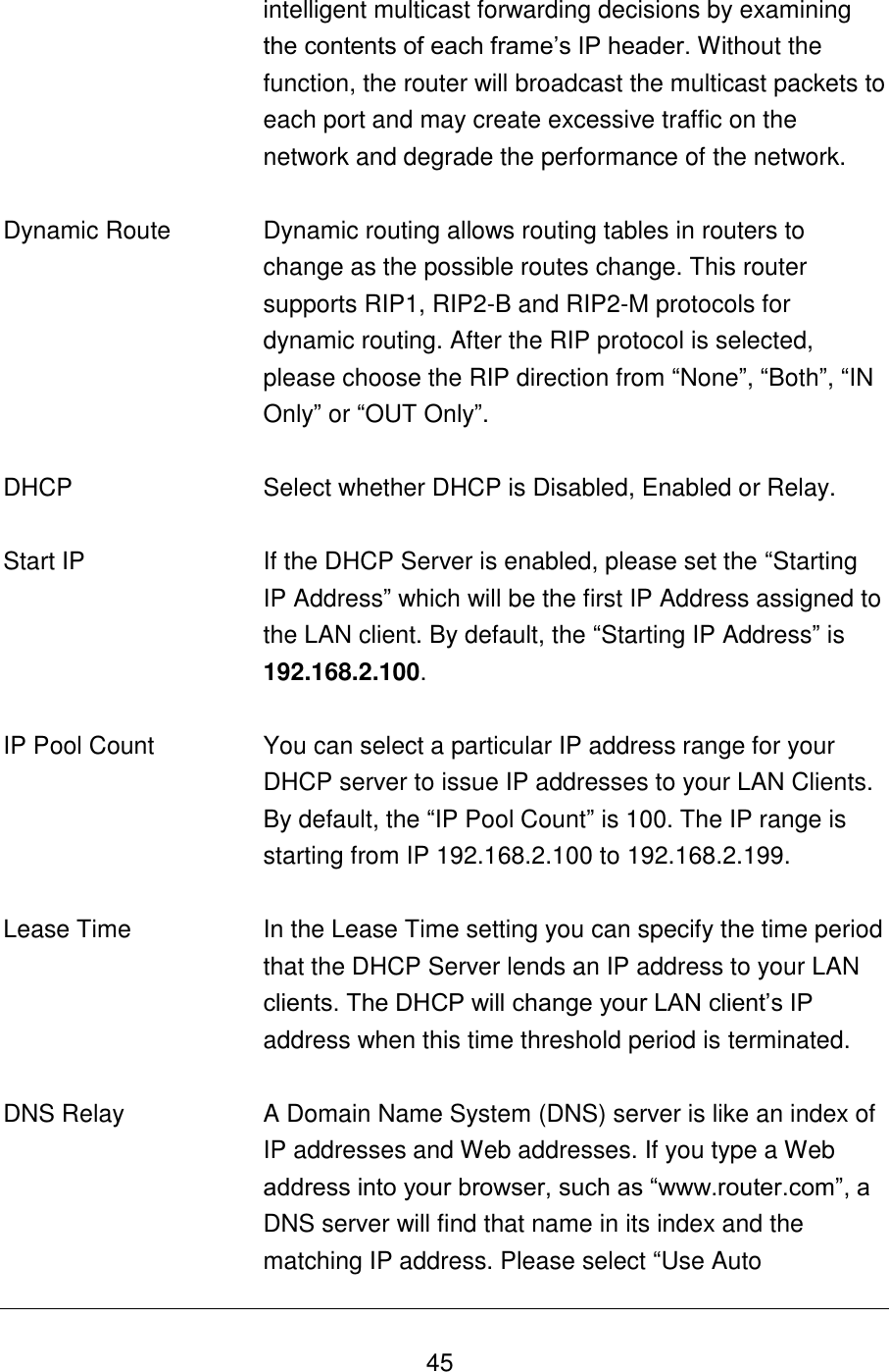
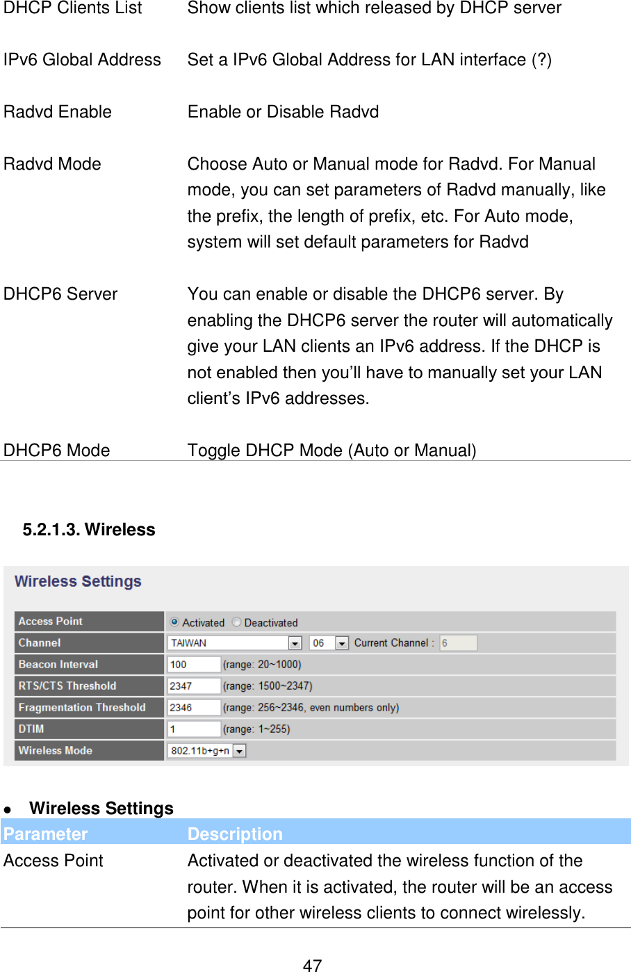
Edimax Technology Co 9572671115 300 WLAN ADSL2/2+ Router User Manual
Edimax Technology Co Ltd 300 WLAN ADSL2/2+ Router
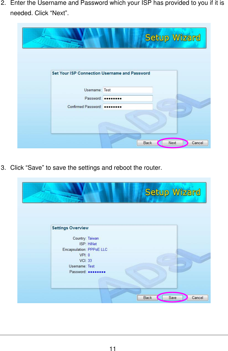
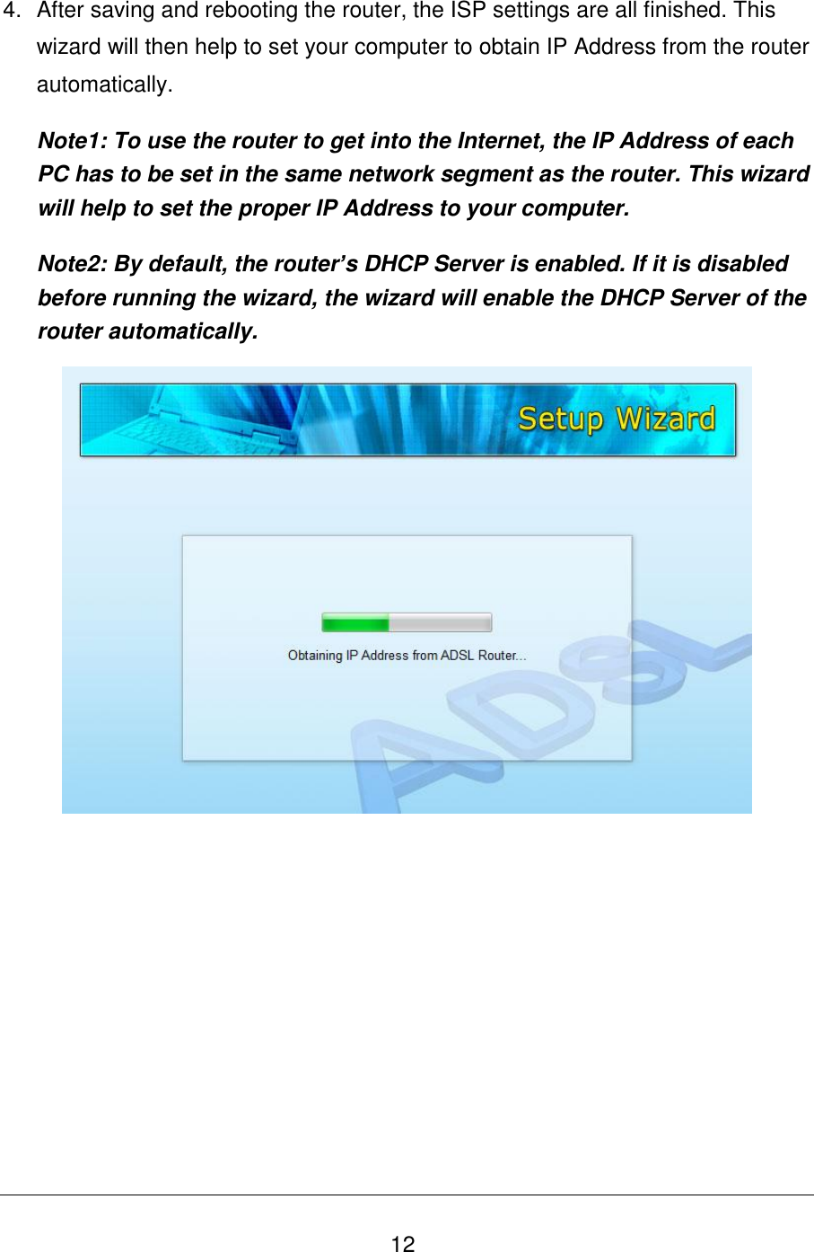
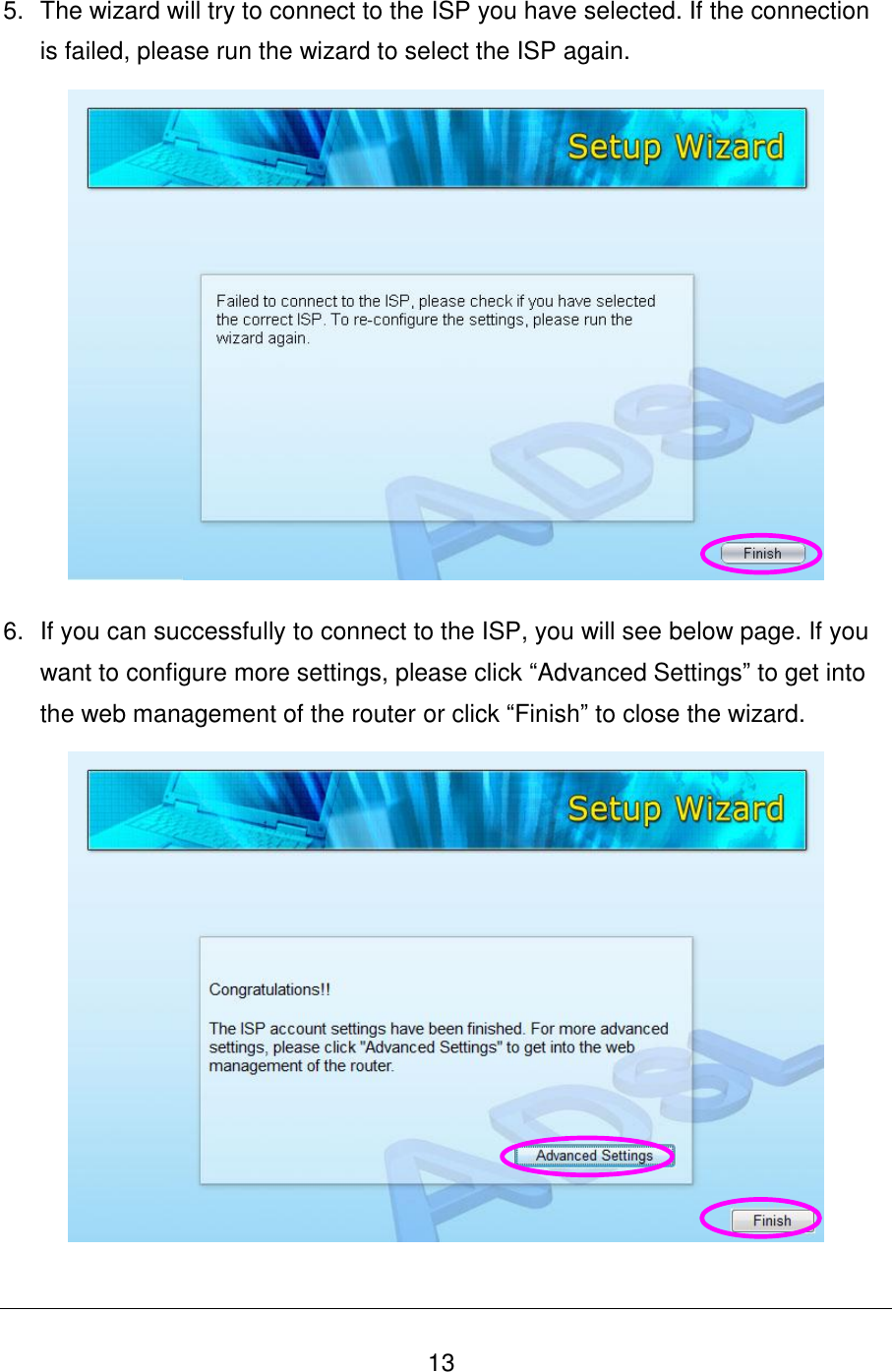
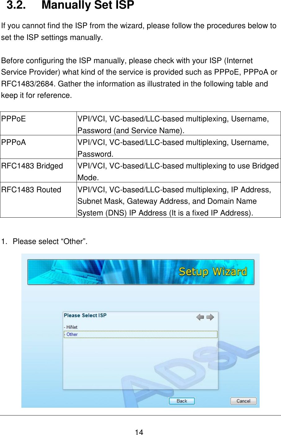
UserManual.wiki
>
Edimax Technology Co
>
9572671115 User Manual
user manual
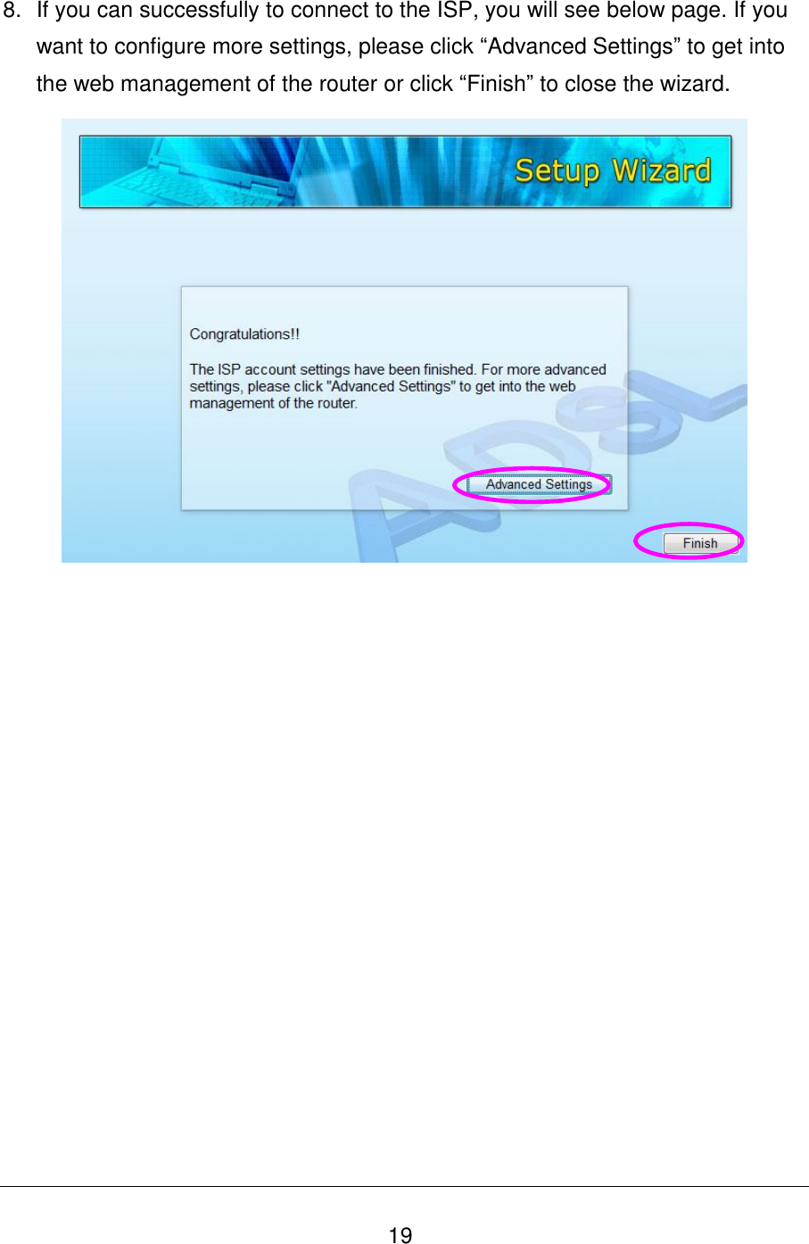
Navigation menu
Upload a User Manual
Namespaces
Wiki Guide
HTML
PDF
Info
Views
User Manual
Discussion / Help
Navigation

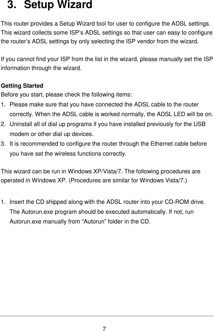
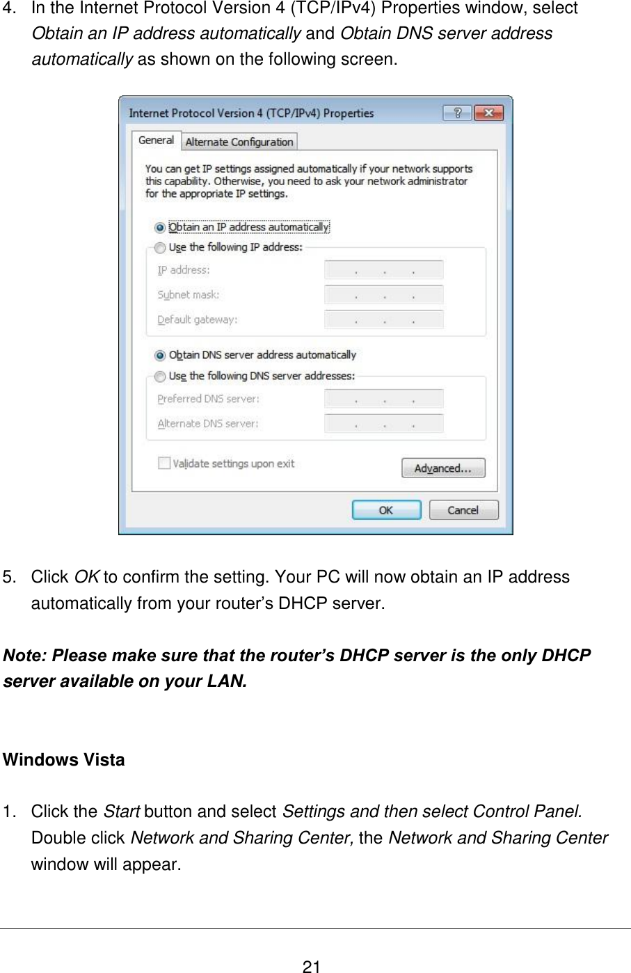
![23 Windows XP 1. Click the Start button and select Control Panel and then double click Network Connections. The Network Connections window will appear. 2. Right click on the Local Area Connection icon and select Properties. The Local Area Connection window will appear. 3. Check your list of Network Components. You should see Internet Protocol [TCP/IP] on your list. Select it and click the Properties button. 4. In the Internet Protocol (TCP/IP) Properties window, select Obtain an IP address automatically and Obtain DNS server address automatically as shown on the following screen.](https://usermanual.wiki/Edimax-Technology-Co/9572671115/User-Guide-1698051-Page-31.png)