Edimax Technology Co 9572671115 300 WLAN ADSL2/2+ Router User Manual
Edimax Technology Co Ltd 300 WLAN ADSL2/2+ Router
user manual

300N WLAN
ADSL 2/2+ Router
User’s Manual
Version: 1.1
(March, 2012)

COPYRIGHT
Copyright 2011/2012 by this company. All rights reserved. No part of this
publication may be reproduced, transmitted, transcribed, stored in a retrieval
system, or translated into any language or computer language, in any form or by
any means, electronic, mechanical, magnetic, optical, chemical, manual or
otherwise, without the prior written permission of this company.

Federal Communication Commission
Interference Statement
FCC Part 68
This equipment complies with Part 68 of the FCC Rules. On the bottom of this
equipment is a label that contains the FCC Registration Number and Ringer
Equivalence Number (REN) for this equipment. You must provide this information
to the telephone company upon request.
The REN is useful to determine the quantity of devices you may connect to the
telephone line and still have all of those devices ring when your number is
called.
In most, but not all areas, the sum of the REN of all devices connected to one
line should not exceed five (5.0). To be certain of the number of devices you may
connect to your line, as determined by the REN, you should contact your local
telephone company to determine the maximum REN for your calling area.
If the modem causes harm to the telephone network, the telephone company
may discontinue your service temporarily. If possible, they will notify you in
advance.
But if advance notice isn't practical, you will be notified as soon as possible. You
will be advised of your right to file a complaint with the FCC.
The telephone company may make changes in its facilities, equipment,
operations, or procedures that could affect the proper operation of your
equipment.
If they do, you will be notified in advance to give you an opportunity to maintain
uninterrupted telephone service.
If you experience trouble with this modem, please contact your dealer for
repair/warranty information. The telephone company may ask you to disconnect

this equipment from the network until the problem has been corrected or you are
sure that the equipment is not malfunctioning.
This equipment may not be used on coin service provided by the telephone
company. Connection to party lines is subject to state tariffs.
Installation
This device is equipped with a USOC RJ11C connector.
FCC Part 15
This equipment has been tested and found to comply with the limits for a Class B
digital device, pursuant to Part 15 of FCC Rules. These limits are designed to
provide reasonable protection against harmful interference in a residential
installation. This equipment generates, uses, and can radiate radio frequency
energy and, if not installed and used in accordance with the instructions, may
cause harmful interference to radio communications. However, there is no
guarantee that interference will not occur in a particular installation. If this
equipment does cause harmful interference to radio or television reception, which
can be determined by turning the equipment off and on, the user is encouraged
to try to correct the interference by one or more of the following measures:
1. Reorient or relocate the receiving antenna.
2. Increase the separation between the equipment and receiver.
3. Connect the equipment into an outlet on a circuit different from that to
which the receiver is connected.
4. Consult the dealer or an experienced radio technician for help.

FCC Caution
This equipment must be installed and operated in accordance with provided
instructions and a minimum 20 cm spacing must be provided between computer
mounted antenna and person’s body (excluding extremities of hands, wrist and
feet) during wireless modes of operation.
This device complies with Part 15 of the FCC Rules. Operation is subject to the
following two conditions: (1) this device may not cause harmful interference, and
(2) this device must accept any interference received, including interference that
may cause undesired operation.
Any changes or modifications not expressly approved by the party responsible for
compliance could void the authority to operate equipment.
Federal Communication Commission (FCC) Radiation Exposure Statement
This equipment complies with FCC radiation exposure set forth for an
uncontrolled environment. In order to avoid the possibility of exceeding the FCC
radio frequency exposure limits, human proximity to the antenna shall not be less
than 20cm (8 inches) during normal operation.
The antenna(s) used for this transmitter must not be co-located or operating in
conjunction with any other antenna or transmitter.
The equipment version marketed in US is restricted to usage of the channels 1-
11 only.

R&TTE Compliance Statement
This equipment complies with all the requirements of DIRECTIVE 1999/5/EC OF
THE EUROPEAN PARLIAMENT AND THE COUNCIL of March 9, 1999 on radio
equipment and telecommunication terminal Equipment and the mutual
recognition of their conformity (R&TTE).
The R&TTE Directive repeals and replaces in the directive 98/13/EEC
(Telecommunications Terminal Equipment and Satellite Earth Station Equipment)
As of April 8, 2000.
Safety
This equipment is designed with the utmost care for the safety of those who
install and use it. However, special attention must be paid to the dangers of
electric shock and static electricity when working with electrical equipment. All
guidelines of this and of the computer manufacture must therefore be allowed at
all times to ensure the safe use of the equipment.
EU Countries Intended for Use
The ETSI version of this device is intended for home and office use in Austria,
Belgium, Denmark, Finland, France, Germany, Greece, Ireland, Italy,
Luxembourg, the Netherlands, Portugal, Spain, Sweden, and the United Kingdom.
The ETSI version of this device is also authorized for use in EFTA member states:
Iceland, Liechtenstein, Norway, and Switzerland.
EU Countries Not intended for use
None.

Contents
1. INTRODUCTION ....................................................... 1
1.1. FEATURES ............................................................................. 2
1.2. MINIMUM REQUIREMENTS ................................................... 3
1.3. PACKAGE CONTENT ............................................................. 3
1.4. HARDWARE PLACEMENT ..................................................... 4
1.4.1. Rear Panel .................................................................................. 4
1.4.2. Front LEDs ................................................................................. 5
2. HARDWARE INSTALLATION ............................... 6
3. SETUP WIZARD ........................................................ 7
3.1. AUTOMATICALLY SET ISP ................................................. 10
3.2. MANUALLY SET ISP........................................................... 14
4. IP ADDRESS SETTING ........................................... 20
5. WEB MANAGEMENT CONFIGURATION ......... 25
5.1. QUICK START ..................................................................... 27
5.2. GENERAL SETUP ................................................................. 31
5.2.1. Internet Setup ........................................................................... 31
5.2.1.1. Internet Settings ................................................................................ 31
5.2.1.2. LAN .................................................................................................. 43
5.2.1.3. Wireless ............................................................................................. 47
5.2.2. Advanced Setup ........................................................................ 55
5.2.2.1. Firewall ............................................................................................. 55
5.2.2.2. Routing .............................................................................................. 55
5.2.2.3. NAT .................................................................................................. 57
5.2.2.3.1. NAT .................................................................................................. 57
5.2.2.3.2. DMZ .................................................................................................. 58
5.2.2.3.3. Virtual Server .................................................................................... 59
5.2.2.4. ADSL ................................................................................................ 60
5.2.2.5. QoS ................................................................................................... 60
5.2.2.6. PortBinding ....................................................................................... 63

5.2.3. Access Management ................................................................. 65
5.2.3.1. UPnP ................................................................................................. 65
5.2.3.2. DDNS ................................................................................................ 65
5.2.3.3. ACL ................................................................................................... 66
5.2.3.4. Filter .................................................................................................. 68
5.2.3.4.1. IP/MAC Filter ................................................................................... 69
5.2.3.4.2. Application Filter .............................................................................. 71
5.2.3.4.3. URL Filter ......................................................................................... 71
5.3. STATUS ............................................................................... 73
5.3.1. Device Info ............................................................................... 73
5.3.2. System Log ................................................................................ 74
5.3.3. Statistics ................................................................................... 75
5.4. TOOLS ................................................................................. 76
5.4.1. Administrator ........................................................................... 76
5.4.2. Time Zone ................................................................................. 76
5.4.3. Firmware .................................................................................. 77
5.4.4. System Restart .......................................................................... 78
5.4.5. Diagnostics ............................................................................... 79
6. TROUBLESHOOTING ............................................ 80
7. GLOSSARY ............................................................... 84
Note:
The setup images used in this manual are for reference only.
The contents of these images may vary according to firmware
version. The official image contents are based on the newest
firmware version.

1
1. Introduction
Congratulations on purchasing this Wireless N ADSL2/2+ Router. This router is a
cost-effective ADSL2+ router, with the combination of an ADSL2+ modem, router,
Ethernet network switch and wireless access point, you can surf the Internet
through your ADSL2/2+ broadband connection without investing other devices.
This router can support downstream transmission rates of up to 24Mbps and
upstream transmission rates of up to 1Mbps. It supports PPPoA (RFC 2364 -
PPP over ATM Adaptation Layer 5), RFC 1483/2684 encapsulation over ATM
(bridged or routed) and PPP over Ethernet (RFC 2516) to establish a connection
with ISP. The product also supports VC-based and LLC-based multiplexing.
With built-in IEEE 802.11b/g/n wireless network capability, all computers and
wireless-enabled network devices (including PDA, cellular phone, game console,
and more!) can connect to this ADSL router without additional cabling. New Draft-
N wireless capability also gives you the highest speed of wireless experience
ever! With a compatible wireless card installed in your PC, you can transfer file
for up to 300Mbps (transfer data rate)! The radio coverage is also doubled, so
don’t worry if your office or house is really big!
Utilizing the web management interface, users can easily configure the various
functions of the router including DHCP server, NAT, virtual server, DMZ, access
control, IP/MAC/Application/URL filter, Firewall, PPTP/IPSec/L2TP pass-through,
DDNS, UPnP, Wireless and etc.
This router is a high performance and high-speed device that provides a full rate
of ADSL2+ standard with the superb reliability and a complete solution for home
and office application.

2
1.1. Features
ADSL2/2+ Compliance
Support downstream rates of up to 24Mbps and upstream rates of up to
1Mbps.
Compliant to ITU-T G.992.1 (G.dmt), G.992.2 (G.lite), G.992.3 (ADSL2),
G.992.4 (splitterless ADSL2), G.992.5 (ADSL2+) for Annex A, B. (Annex A
and B are supported in different H/W platform)
Supports Multi-Mode standard (ANSI T1.413, Issue 2; G.dmt (G.992.1);
G.994.1 and G.996.1 (for ISDN only); G.991.1;G.lite (G992.2)).
Multiple Protocols over AAL5 (RFC 1483/2684).
PPP over AAL5 (RFC 2364).
PPP over Ethernet (RFC 2516).
Support 802.11n Wireless Access Point
Complies with IEEE 802.11b/g/n standards.
Farther coverage, less dead spaces and higher throughput with MIMO
technology.
High data rate – up to 300Mbps network speed.
Supports 64-bit/128-bit WEP, WPA-PSK and WPA2-PSK wireless security
functions.
Supports WPS (WiFi Protected Setup) to easy connect wireless network
without configuring the security.
Supports MAC address filtering.
Router
NAT (Network Address Translation) IP Sharing
Virtual Server
DMZ
VPN Pass Through (IPSec/PPTP/L2TP)
SPI Anti-DOS Firewall
DHCP Server and Client
Access Management
ACL (Access Control)

3
IP/MAC/Application/URL Filter
UPnP (Universal Plug and Play)
Dynamic DNS
1.2. Minimum Requirements
The following devices are necessary to configure and use the ADSL2+ Router:
A PC with Pre-installed Ethernet Adapter (Required) and a Web-Browser
(Internet Explorer 4.0 or higher)
RJ-45 Ethernet crossover cable (Included in the package)
RJ-11 (ADSL Ready) phone Line
1.3. Package Content
One ADSL2/2+ Router (Annex A or B)
One Power Adapter (12VDC, 1A)
One RJ-45 Ethernet Cable (50 cm)
One RJ-11 Telephone Line (180 cm)
One CD with full User Manual and Quick Installation Guide and Setup
Wizard.
4
1.4. Hardware Placement
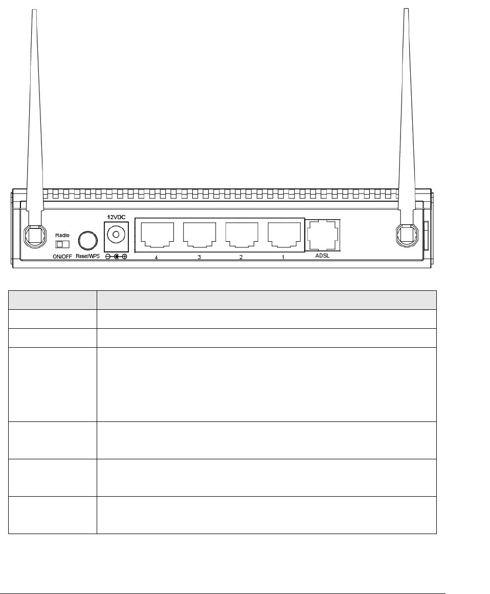
1.4.1. Rear Panel
Item Name
Description
Antenna A/B
These antennas are dipole antennas.
Radio ON/OFF
Switch the button to activate or deactivate the wireless functions.
Reset / WPS
Reset the router to factory default settings (clear all settings) or start
WPS function. Press this button and hold for 10 seconds to restore all
settings to factory defaults, and press this button for less than 5 seconds
to start WPS function.
1 - 4
The router’s 4 LAN ports are where you connect your LAN’s PCs, printer
servers, hubs and switches etc.
ADSL
Connect the supplied RJ-11 telephone line to this port and your
ADSL/telephone network.
Power
Please plug the power adapter attached with the ADSL Router to the
power jack. The power adapter is 12VDC, 1A.
Antenna B
Antenna A

5
1.4.2. Front LEDs
On the router’s front panel there are LED lights that inform you of the router’s
current status. Below is an explanation of each LED and its description.
LED
Light Status
Description
PWR (Green)
On
Router is switched on and correctly
powered.
WLAN (Yellow)
On
Off
Wireless LAN WPS is on.
Wireless LAN is disabled
Blinking
Wireless traffic is transmitting or receiving
ADSL (Green)
On
Connected to an ADSL DSLAN
successfully
Blinking
No connection
LAN LNK/ACT (Port 1-4)
On
The LAN cable is connected to the router
Off
No network connection.
Blinking
Network traffic transferring or receiving
through the LAN port

6
2. Hardware Installation
Step 1. Connect the ADSL Line
Connect the router to your ADSL cable through the supplied RJ-11 telephone line.
Step 2. Connect the router to your LAN network
Connect the router to your PC, hub or switch by attached the Ethernet cable to
the LAN port of the router.
Step 3. Connect the Power Adapter to the Router
Connect the power adapter to the power jack on the rear panel of router.
Step4: Check the ADSL LED on the Router
The ADSL LED will be ON if the router is connected to the ADSL cable and
receives the ADSL signals successfully. If the LED is blinking, please contact
with your ISP (Internet Service Provider) to check the problem.
Note: You must use the power adapter shipped along with the router, do
NOT use any other power adapter from other sources.

7
3. Setup Wizard
This router provides a Setup Wizard tool for user to configure the ADSL settings.
This wizard collects some ISP’s ADSL settings so that user can easy to configure
the router’s ADSL settings by only selecting the ISP vendor from the wizard.
If you cannot find your ISP from the list in the wizard, please manually set the ISP
information through the wizard.
Getting Started
Before you start, please check the following items:
1. Please make sure that you have connected the ADSL cable to the router
correctly. When the ADSL cable is worked normally, the ADSL LED will be on.
2. Uninstall all of dial up programs if you have installed previously for the USB
modem or other dial up devices.
3. It is recommended to configure the router through the Ethernet cable before
you have set the wireless functions correctly.
This wizard can be run in Windows XP/Vista/7. The following procedures are
operated in Windows XP. (Procedures are similar for Windows Vista/7.)
1. Insert the CD shipped along with the ADSL router into your CD-ROM drive.
The Autorun.exe program should be executed automatically. If not, run
Autorun.exe manually from “Autorun” folder in the CD.
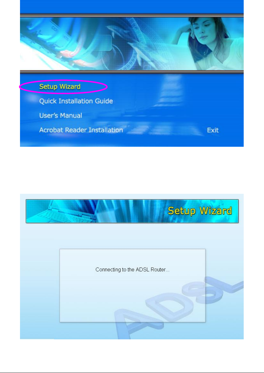
8
2. The following screen will be displayed. Click “Setup Wizard”.
3. This wizard will be executed and try to search for the ADSL Router. If the
ADSL Router can be searched successfully, the wizard will guide you to step
5.
9
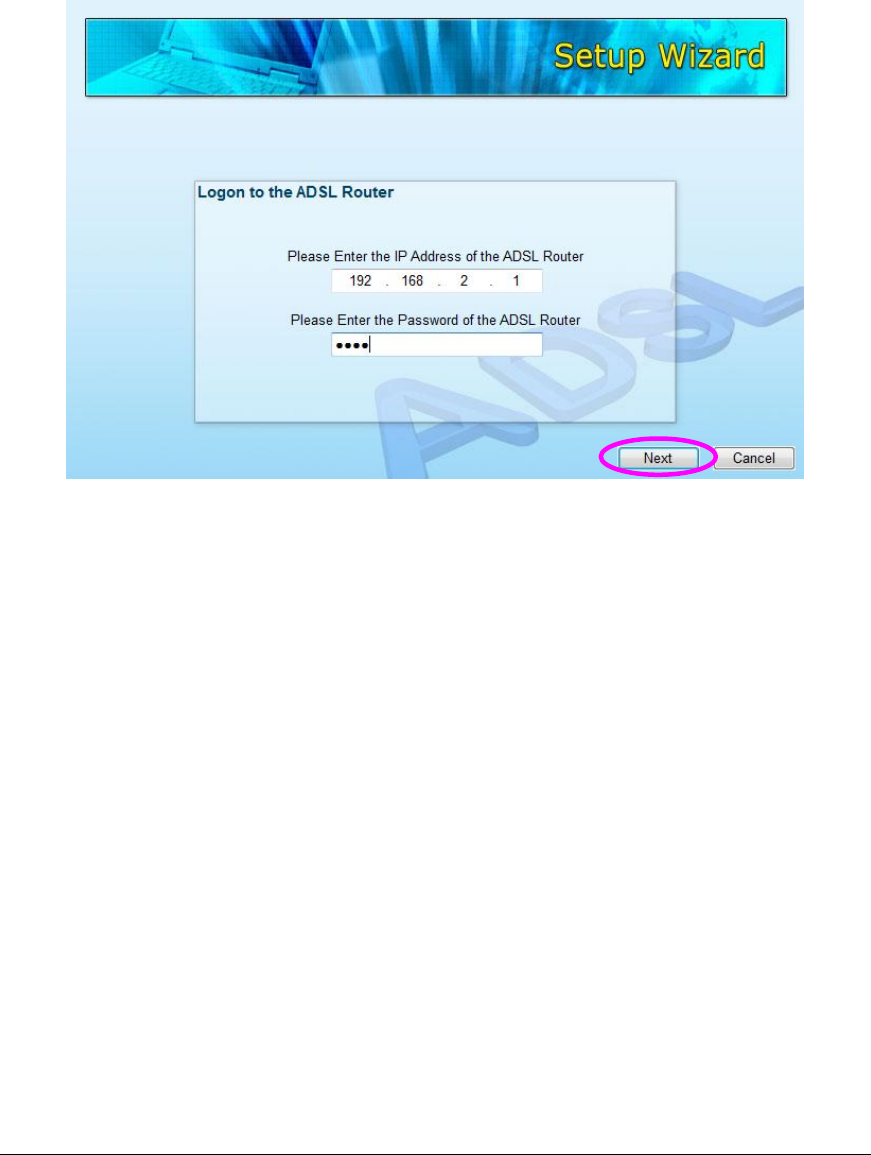
4. If the router cannot be found, please enter the IP Address and the Password
of the router to search again. Click “Next” to continue.
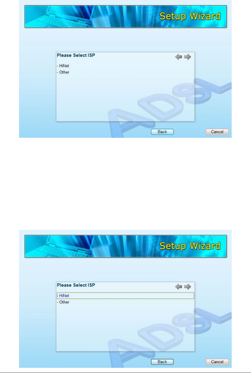
5. The wizard will automatically select the country where you are in by checking
the language of the operating system in your computer and skip to the “Select
ISP” page. Please select the ISP.
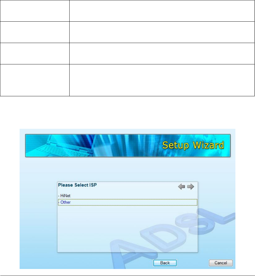
If you cannot find the ISP, please click “Other” to reselect the country or
manual configure the ISP information.
10
3.1. Automatically Set ISP
If you can find the ISP from the wizard, please follow the procedures below to let
the wizard set the ISP settings automatically.
1. Please select the ISP (Internet Service Provider) of your ADSL service.
11
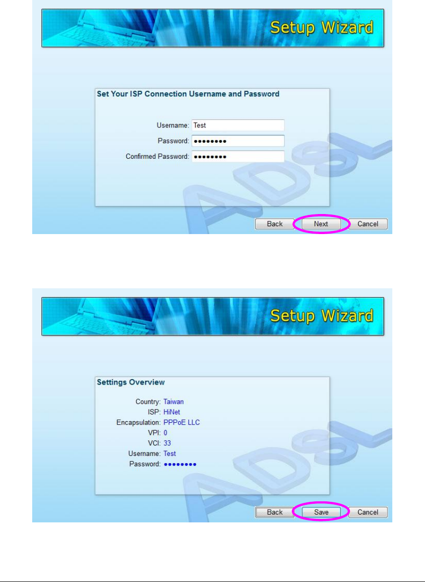
2. Enter the Username and Password which your ISP has provided to you if it is
needed. Click “Next”.
3. Click “Save” to save the settings and reboot the router.
12
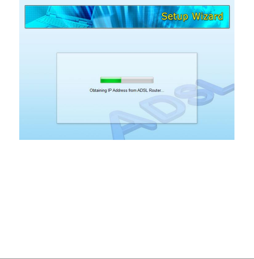
4. After saving and rebooting the router, the ISP settings are all finished. This
wizard will then help to set your computer to obtain IP Address from the router
automatically.
Note1: To use the router to get into the Internet, the IP Address of each
PC has to be set in the same network segment as the router. This wizard
will help to set the proper IP Address to your computer.
Note2: By default, the router’s DHCP Server is enabled. If it is disabled
before running the wizard, the wizard will enable the DHCP Server of the
router automatically.
13
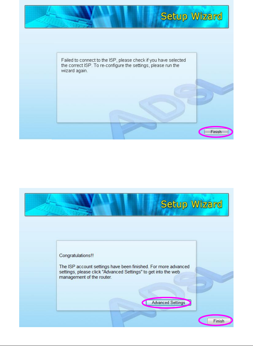
5. The wizard will try to connect to the ISP you have selected. If the connection
is failed, please run the wizard to select the ISP again.
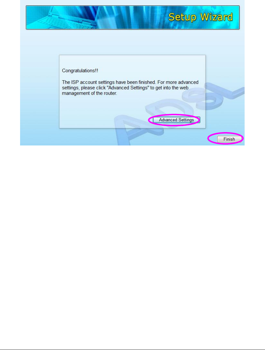
6. If you can successfully to connect to the ISP, you will see below page. If you
want to configure more settings, please click “Advanced Settings” to get into
the web management of the router or click “Finish” to close the wizard.
14
3.2. Manually Set ISP
If you cannot find the ISP from the wizard, please follow the procedures below to
set the ISP settings manually.
Before configuring the ISP manually, please check with your ISP (Internet
Service Provider) what kind of the service is provided such as PPPoE, PPPoA or
RFC1483/2684. Gather the information as illustrated in the following table and
keep it for reference.
PPPoE
VPI/VCI, VC-based/LLC-based multiplexing, Username,
Password (and Service Name).
PPPoA
VPI/VCI, VC-based/LLC-based multiplexing, Username,
Password.
RFC1483 Bridged
VPI/VCI, VC-based/LLC-based multiplexing to use Bridged
Mode.
RFC1483 Routed
VPI/VCI, VC-based/LLC-based multiplexing, IP Address,
Subnet Mask, Gateway Address, and Domain Name
System (DNS) IP Address (It is a fixed IP Address).
1. Please select “Other”.
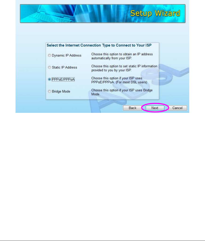
15
2. Please check with your ISP the connection type of the ADSL line. Select the
Connection Type and click “Next”.
Note: The wizard will automatically select the country where you are in
by checking the language of the operating system in your computer and
skip to the “Select ISP” page. If you want to change the country, please
click “Back” from this page.
16
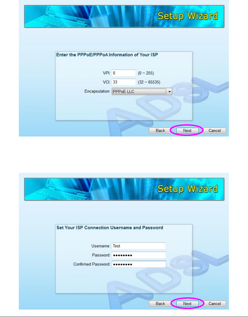
3. Input the VPI, VCI and Encapsulation data supplied by your ISP. If the
Connection Type is “Static IP Address”, you have to input the IP Address
information supplied by your ISP. To know more about the explanation of
each setting, please refer to Section 5.2 in the manual.
4. Enter the Username and Password which your ISP has provided to you if it is
needed. Click “Next”.
17
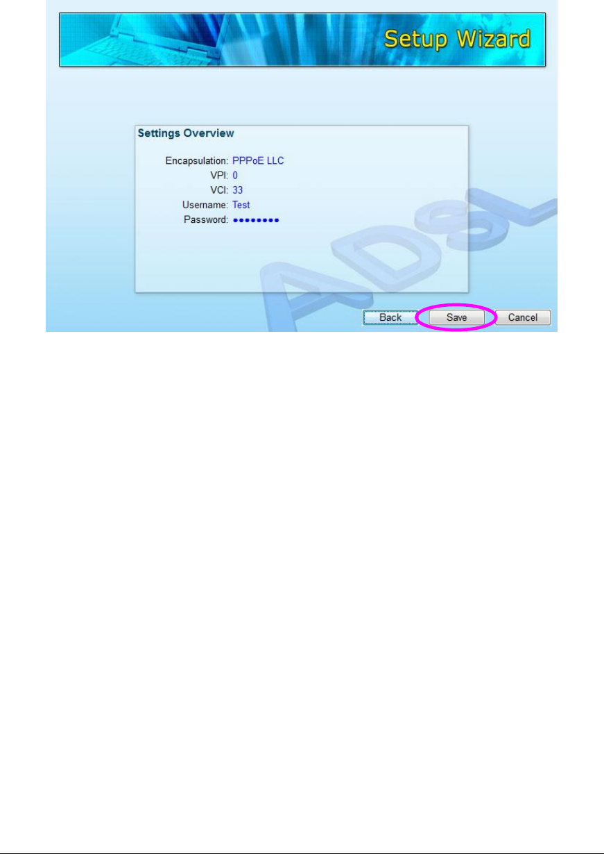
5. Click “Save” to save the settings and reboot the router.
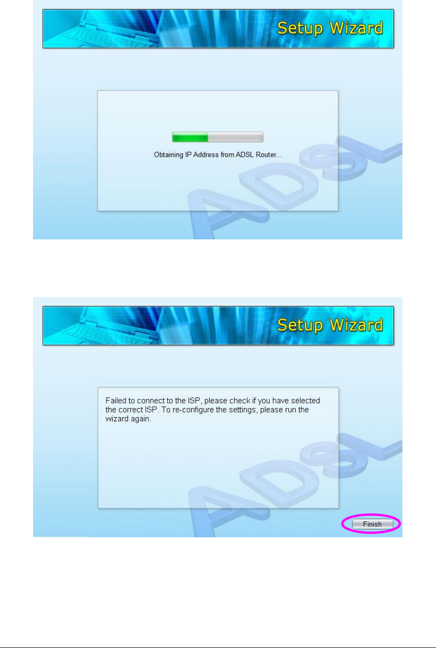
6. After saving and rebooting the router, the ISP settings are all finished. This
wizard will then help to set your computer to obtain IP Address from the router
automatically.
Note1: To use the router to get into the Internet, the IP Address of each
PC has to be set in the same network segment as the router. This wizard
will help to set the proper IP Address to your computer.
Note2: By default, the router’s DHCP Server is enabled. If it is disabled
before running the wizard, the wizard will enable the DHCP Server of the
router automatically.
18
7. The wizard will try to connect to the ISP you have selected. If the connection
is failed, please run the wizard to select the ISP again.
19
8. If you can successfully to connect to the ISP, you will see below page. If you
want to configure more settings, please click “Advanced Settings” to get into
the web management of the router or click “Finish” to close the wizard.

20
4. IP Address Setting
Using the router to get into the Internet, the PCs in the network must have
Ethernet adapter installed and be connected to the router either directly or
through a hub or switch. The TCP/IP protocol of each PC has to been installed
and the IP Address of each PC has to be set in the same subnet as the router.
The router’s default IP Address is 192.168.2.1 and the subnet mask is
255.255.255.0. PCs can be configured to obtain IP Address automatically
through the DHCP Server of the router or a fixed IP Address in order to be in the
same subnet as the router. By default, the DHCP Server of the router is enabled
and will dispatch IP Address to PC from 192.168.2.100 to 192.168.2.200. It is
strongly recommended to set obtaining IP address automatically.
This section shows you how to configure your PC’s so that it can obtain an IP
address automatically for either Windows 95/98/Me, 2000 or NT operating
systems. For other operating systems (Macintosh, Sun, etc.), please follow the
manual of the operating systems. The following is a step-by-step illustration on
how to configure your PC to obtain an IP address automatically for Windows 7,
Windows Vista, Windows XP.
Windows 7
1. Click the Start button and select Control Panel. Double click Network and
Internet and click Network and Sharing Center, the Network and Sharing
Center window will appear.
2. Click Change adapter settings and right click on the Local Area Connection
icon and select Properties. The Local Area Connection window will appear.
3. Check your list of Network Components. You should see Internet Protocol
Version 4 (TCP/IPv4) on your list. Select it and click the Properties button.
21
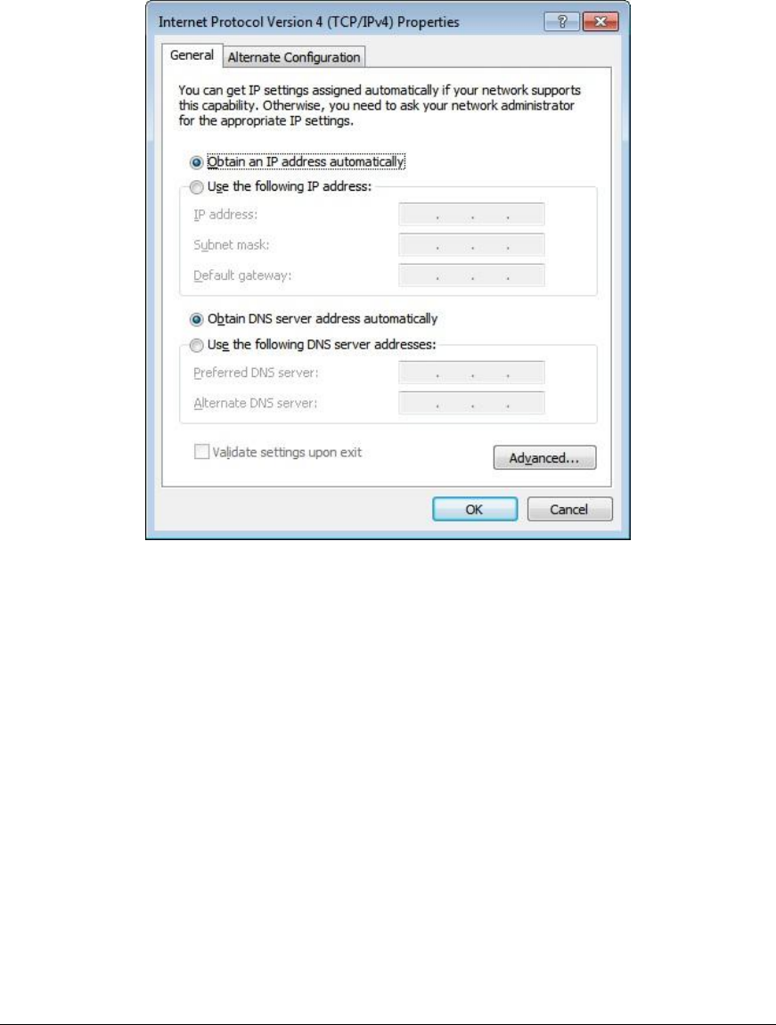
4. In the Internet Protocol Version 4 (TCP/IPv4) Properties window, select
Obtain an IP address automatically and Obtain DNS server address
automatically as shown on the following screen.
5. Click OK to confirm the setting. Your PC will now obtain an IP address
automatically from your router’s DHCP server.
Note: Please make sure that the router’s DHCP server is the only DHCP
server available on your LAN.
Windows Vista
1. Click the Start button and select Settings and then select Control Panel.
Double click Network and Sharing Center, the Network and Sharing Center
window will appear.
22
2. Click Manage network connections and right click on the Local Area
Connection icon and select Properties. The Local Area Connection window
will appear.
3. Check your list of Network Components. You should see Internet Protocol
Version 4 (TCP/IPv4) on your list. Select it and click the Properties button.
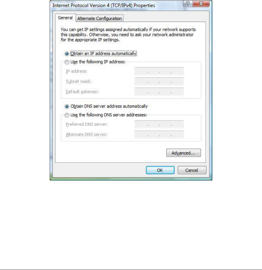
4. In the Internet Protocol Version 4 (TCP/IPv4) Properties window, select
Obtain an IP address automatically and Obtain DNS server address
automatically as shown on the following screen.
5. Click OK to confirm the setting. Your PC will now obtain an IP address
automatically from your router’s DHCP server.
Note: Please make sure that the router’s DHCP server is the only DHCP
server available on your LAN.
23
Windows XP
1. Click the Start button and select Control Panel and then double click Network
Connections. The Network Connections window will appear.
2. Right click on the Local Area Connection icon and select Properties. The
Local Area Connection window will appear.
3. Check your list of Network Components. You should see Internet Protocol
[TCP/IP] on your list. Select it and click the Properties button.
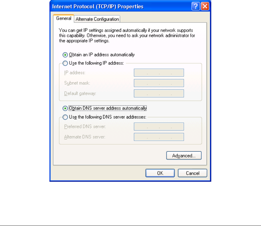
4. In the Internet Protocol (TCP/IP) Properties window, select Obtain an IP
address automatically and Obtain DNS server address automatically as
shown on the following screen.

24
5. Click OK to confirm the setting. Your PC will now obtain an IP address
automatically from your router’s DHCP server.
Note: Please make sure that the router’s DHCP server is the only DHCP
server available on your LAN.
25
5. Web Management Configuration
Once you have configured your PCs to obtain an IP address automatically, the
router’s DHCP server will automatically give your LAN clients an IP address. By
default the router’s DHCP server is enabled so that you can obtain an IP address
automatically. To see if you have obtained an IP address, see Appendix A.
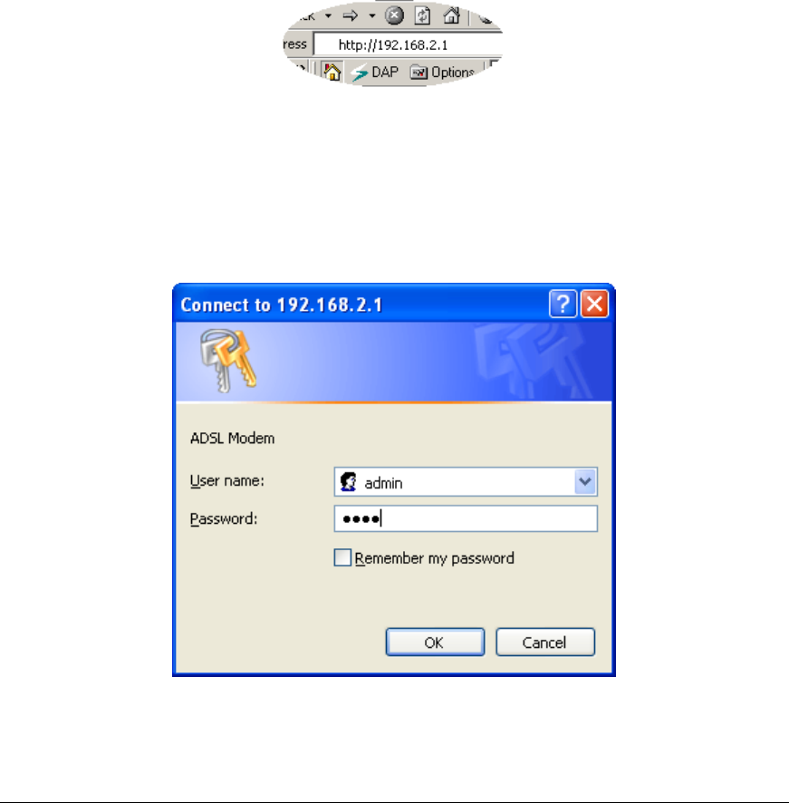
Once your PC has obtained an IP address from your router, enter the default IP
address 192.168.2.1 (router’s IP address) into your PC’s web browser and press
<enter>
The login screen below will appear. Enter the “User Name” and “Password” and
then click <OK> to login. By default the user name is “admin” and the password
is “1234”. For security reasons it is recommended that you change the password
as soon as possible.
26
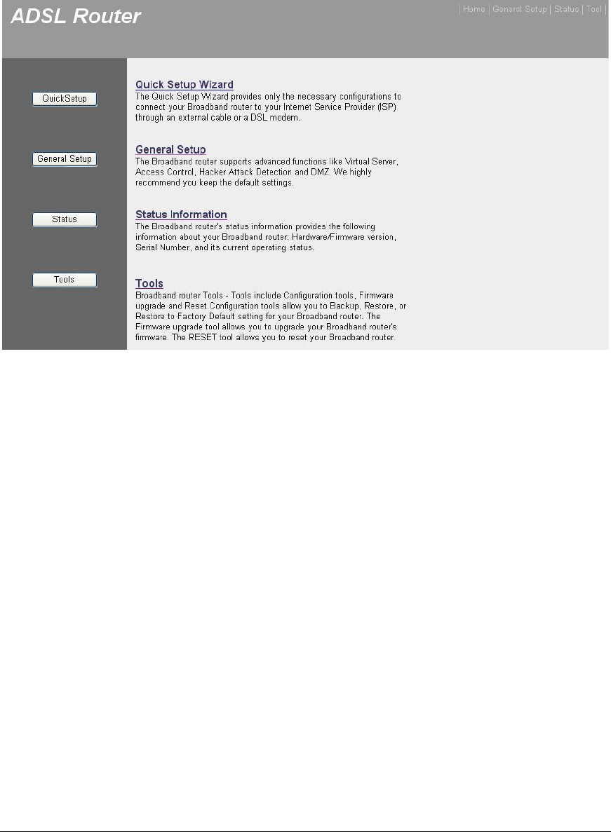
The HOME page screen below will appear. The Home Page is divided into seven
sections: Quick Setup, General Setup, Status, Tools.
Quick Start (Section 5.1)
Follow the setup process in the Quick Start; you can quickly set the router as an
Internet Access device.
General Setup (Section 5.2)
It allows you to configure the Internet, LAN and Wireless access.
Status (Section 5.3)
This section contains configurations for the router’s advanced functions such as
Firewall, Virtual Server, DMZ, ADSL Mode, ADSL Type, etc.
Tools (Section 5.4)
It allows you to configure ACL, IP/MAC/Application/URL Filter, SNMP, UPnP and
DDNS functions.
Help
If you want to know about the settings of the router quickly, please refer to the
description in the Help menu.
27
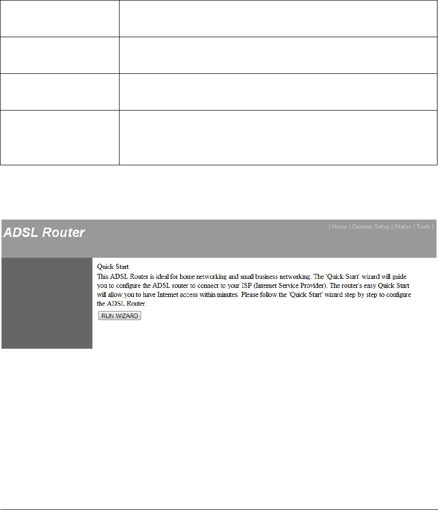
5.1. Quick Start
The Quick Start section is designed to get you using the router as quickly as
possible. Before configuring the router, please check with your ISP (Internet
Service Provider) what kind of the service is provided such as PPPoE, PPPoA or
RFC1483/2684. Gather the information as illustrated in the following table and
keep it for reference.
PPPoE
VPI/VCI, VC-based/LLC-based multiplexing, Username,
Password (and Service Name).
PPPoA
VPI/VCI, VC-based/LLC-based multiplexing, Username,
Password.
RFC1483 Bridged
VPI/VCI, VC-based/LLC-based multiplexing to use Bridged
Mode.
RFC1483 Routed
VPI/VCI, VC-based/LLC-based multiplexing, IP Address,
Subnet Mask, Gateway Address, and Domain Name
System (DNS) IP Address (It is a fixed IP Address).
In the Quick Start, click “Run Wizard” to start the configuration.
28
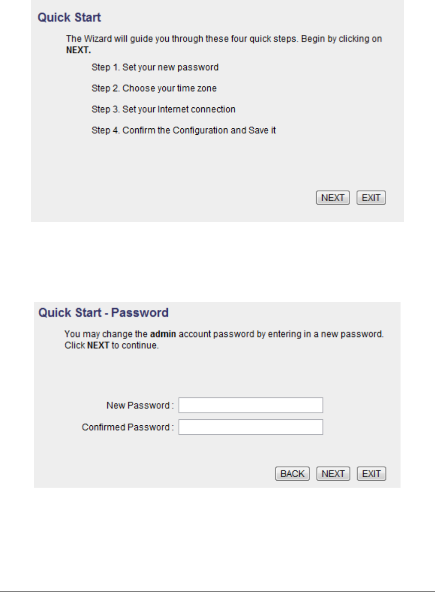
Please follow the steps in the setup wizard to complete the configuration of the
Internet connection.
Step 1: Set your new password
Please enter the new password and confirm the password again.
29
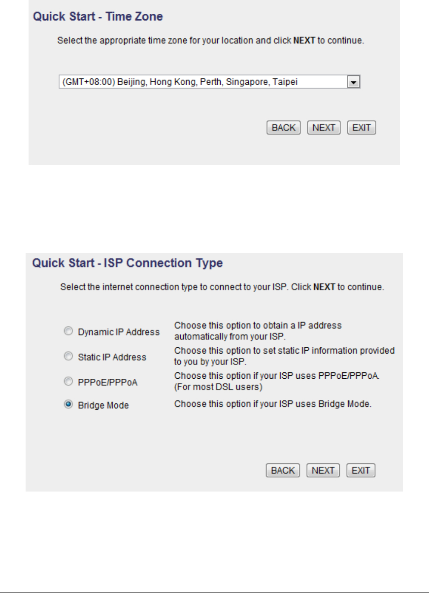
Step 2: Choose your tome zone
Please select the tome zone where you are located.
Step 3: Set your Internet connection
Please check with your ISP the connection type of the ADSL line.
30
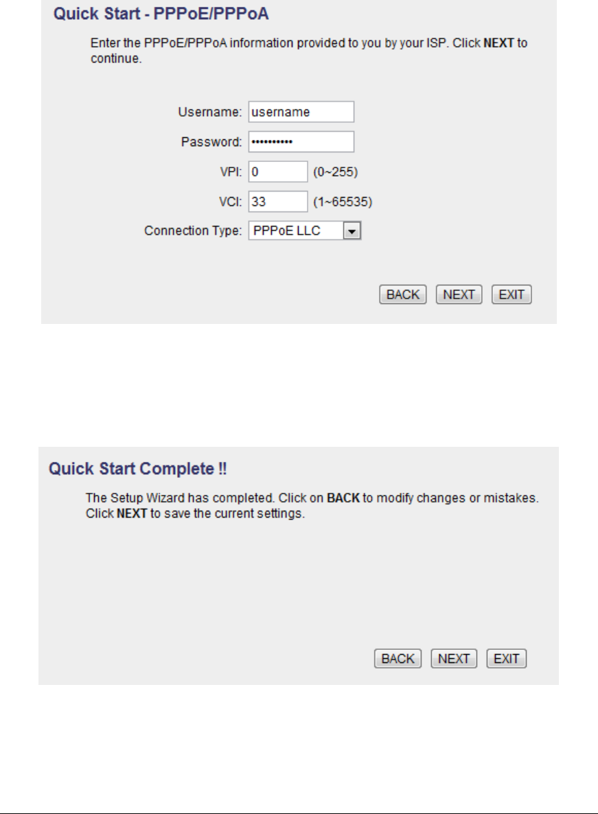
Step 4: Input the data supplied by your ISP
To know more about the explanation of each setting, please refer to Section 5.2.
Step 5: Re-start your ADSL router
Click “Next” to save the settings and restart the router.
31
5.2. General Setup
Please start your web browser and log onto the web management interface of the
router, then click ‘General Setup’ button on the left menu, or click ‘General Setup’
link at the upper-right corner of web management interface.
5.2.1. Internet Setup
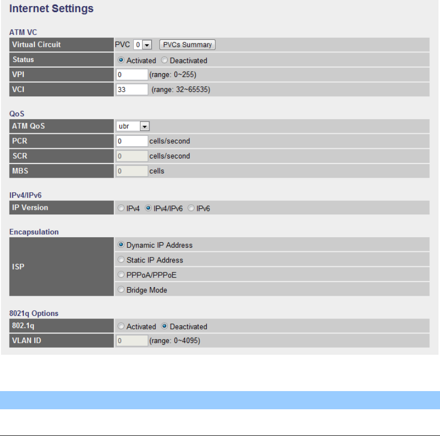
5.2.1.1. Internet Settings
ATM VC
Parameter
Description

32
Virtual Circuit
VPI (Virtual Path Identifier) and VCI (Virtual Channel
Identifier define a virtual circuit.
Status
Each PCV can be toggled Activated or Deactivated.
VPI
VPI is a virtual path determines the way an ATM cell
should be routed. The VPI is an 8-bit (in UNI) or 12-bit (in
NNI) number that is included in the header of an ATM
cell. The valid range for the VPI is 0 to 255. Enter the VPI
assigned by the ISP.
VCI
VCI is the label given to an ATM VC to identify it and
determine its destination. The VCI is a 16-bit number that
is included in the header of an ATM cell. The valid range
for the VCI is 32 to 65535. Enter the VCI assigned by the
ISP.
QoS
Parameter
Description
ATM QoS
UBR (Unspecified Bit Rate) – Select UBR for
applications that are non-time sensitive, such as e-mail.
CBR (Constant Bit Rate) – This class is used for
emulating circuit switching. The cell rate is constant with
time. Select CBR to specify fixed (always on) bandwidth
for voice or data traffic.
rtVBR (real time Variable Bit Rate) – This class is similar
to nrtVBR but is designed for applications that are
sensitive to cell-delay variation. Examples for real-time
VBR are voice with speech activity detection (SAD) and
interactive compressed video.
nrtVBR (non-real time Variable Bit Rate) – This class
allows users to send traffic at a rate that varies with time

33
depending on the availability of user information.
Statistical multiplexing is provided to make optimum use
of network resources. Multimedia e-mail is an example of
nrtVBR.
PCR
Divide the DSL line rate (bps) by 424 (the size of an ATM
cell) to find the PCR (Peak Cell Rate). This is the
maximum rate at which the sender can send cells.
SCR
SCR (Sustain Cell Rate) is the average rate, as
measured over a long interval, in the order of the
connection lifetime.
MBS
MBS (Maximum Burst Size) refers to the maximum
number of cells that can be sent at the peak rate. Type
the MBS, which is less than 65535.
IPv4/IPv6
Parameter
Description
IP Version
You can be toggled IPv4 or IPv4/IPv6 or IPv6 only.
Encapsulation
The router can be connected to your service provider in any of the following ways.
Parameter
Description
Dynamic IP Address
Obtain an IP address automatically from your service
provider.
Static IP Address
Uses a static IP address. Your service provider gives a
static IP address to access Internet services.
PPPoE/PPPoA
PPPoE (PPP over Ethernet) and PPPoA (PPP over
ATM) are common connection methods used for xDSL.
Bridge Mode
Bridge Mode is a common connection method used for
xDSL modem.
34
802.1q Options
Parameter
Description
802.1q
Toggle Activated or Deactivated 802.1q
VLAN ID
Set VLAN ID
After you have selected the ISP Type, this web page will be varied depending on
the ISP Type you select. You have to continue setting some parameters. Please
refer to the following table for the explanation of each parameter.
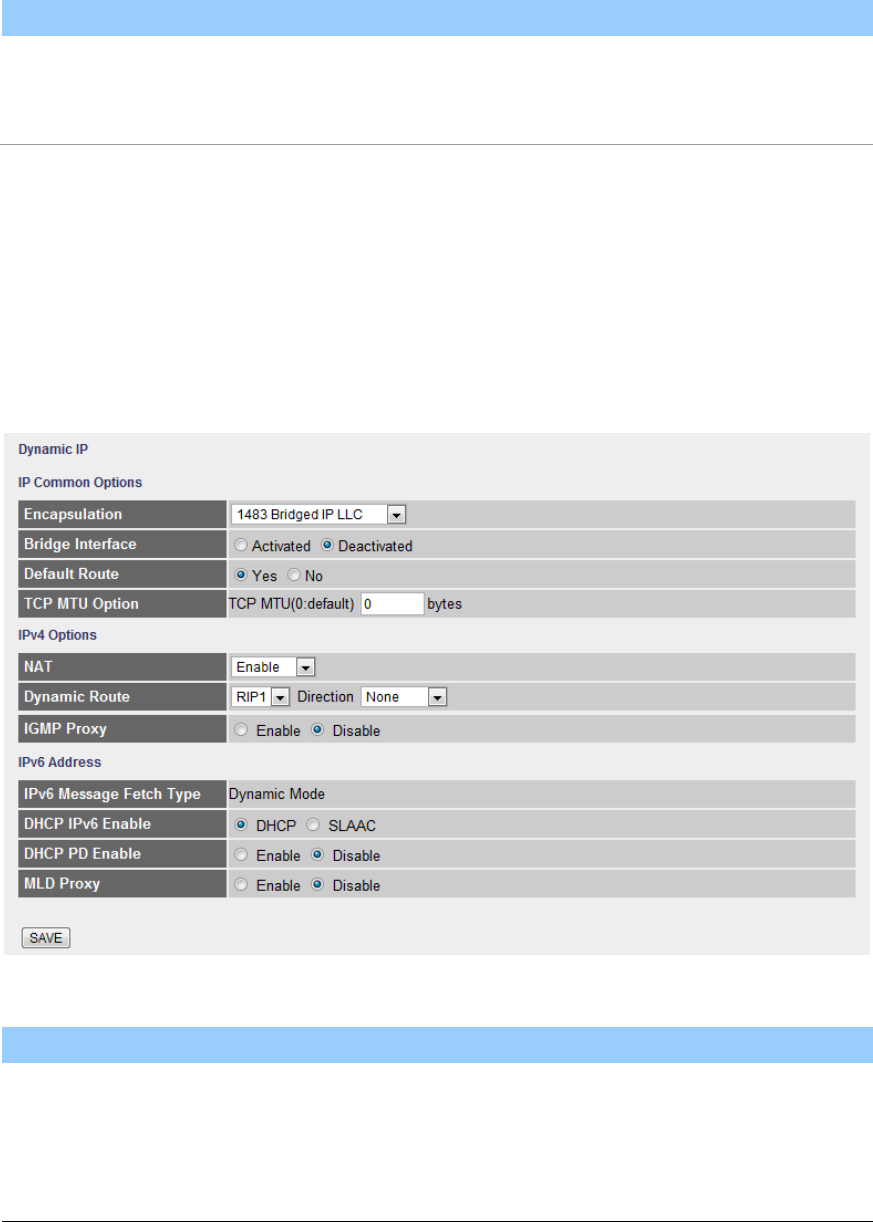
Dynamic IP
IP Common Options
Parameter
Description
Encapsulation
Please check with your ISP the method of multiplexing.
In Bridge Mode, please select “1483 Bridge IP LLC” or
“1483 Bridge IP VC-Mux”.

35
Bridge Interface
This router has built-in ADSL modem and is able to
connect to ISP directly. Alternatively, if you want to use
the dial up software to manually connect to the ISP, you
have to activate the ”Bridge Interface”.
Default Route
When “Default Router” is enabled, all the packets for
destinations not known by the router's routing table are
sent to the default route. By default, it is enabled.
TCP MSS Option
The “TCP MSS Option” enables the configuration of the
maximum segment size (MSS) for transient packets that
traverse a router, specifically TCP segments in the SYN
bit set, when PPPoE is being used in the network. Please
specify the MSS range from 100 to 1452 bytes or 0 byte
as the default value.
IPv4 Options
Parameter
Description
NAT
NAT (Network Address Translation), an Internet standard
that enables a local-area network (LAN) to use one set of
IP addresses for internal traffic and a second set of
addresses for external traffic. When NAT is enabled, the
router will help to make all necessary IP address
translations for the PC connected to the router to access
the Internet.
Dynamic Route
Dynamic routing allows routing tables in routers to
change as the possible routes change. This router
supports RIP1, RIP2-B and RIP2-M protocols for
dynamic routing. After the RIP protocol is selected,
please choose the RIP direction from “None”, “Both”, “IN
Only” or “OUT Only”.
IGMP Porxy
Enable or disable IGMP proxy feature.
36
IPv6 Options
Parameter
Description
IPv6 Message Fetch
Type
The current Mode of the ISP.
DHCP IPv6 Enable
Choose DHCPv6 or (Stateless address
autoconfiguration)SLAAC mode for IPv6
DHCP PD Enable
Enable or disable Prefix Delegation(PD) function of
DHCPv6
MLD Proxy
Enable or disable MLD proxy feature.
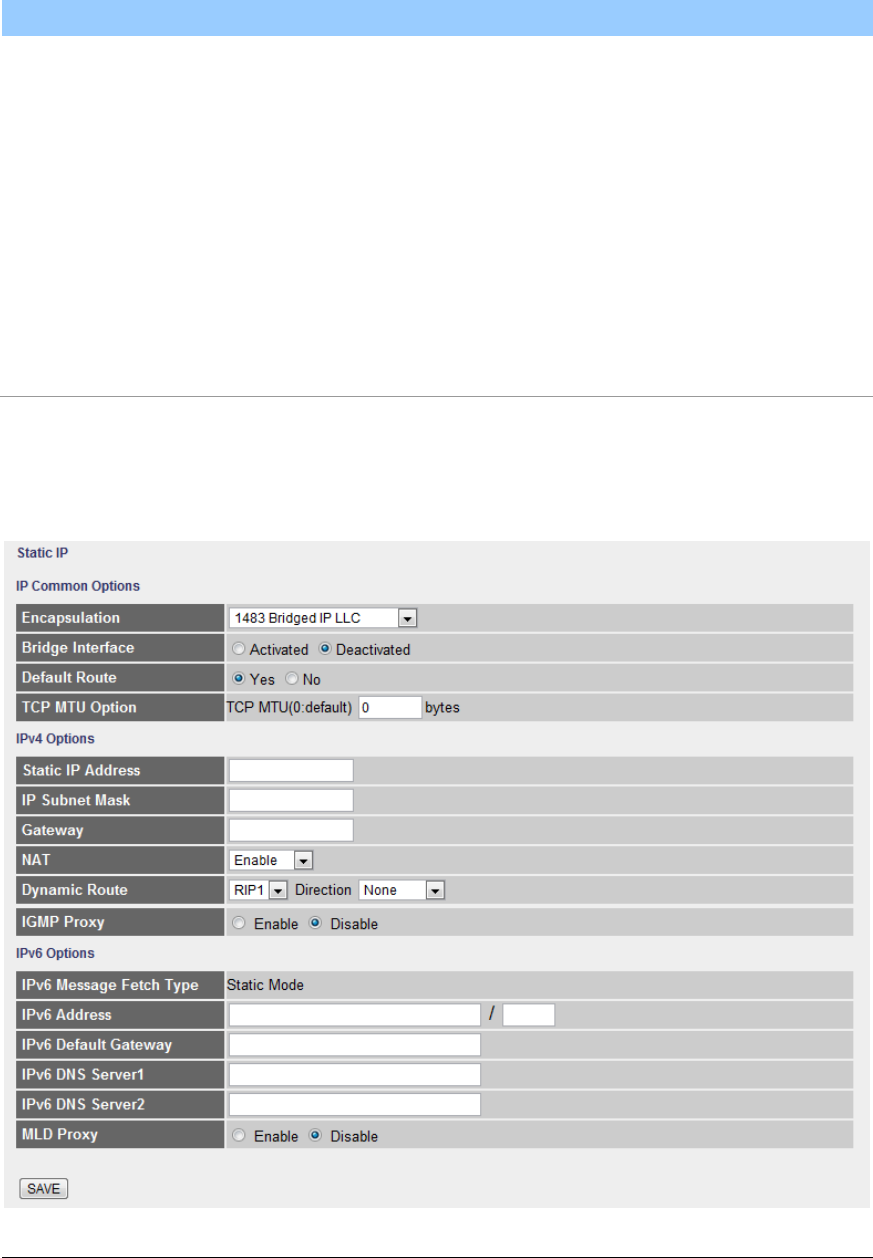
Static IP Address

37
IP Common Options
Parameter
Description
Encapsulation
Please check with your ISP the method of multiplexing.
In Static IP Mode, please select “1483 Bridge IP LLC” or
“1483 Bridge IP VC-Mux” or “1483 Routed IP LLC(IPoA)”
or “1483 Routed IP VC-Mux”.
Bridge Interface
This router has built-in ADSL modem and is able to
connect to ISP directly. Alternatively, if you want to use
the dial up software to manually connect to the ISP, you
have to activate the ”Bridge Interface”.
Default Route
When “Default Router” is enabled, all the packets for
destinations not known by the router's routing table are
sent to the default route. By default, it is enabled.
TCP MTU Option
MTU (Maximum Transmission Unit) determine the
maximum size of each packet in any transmission within
the network. Please specify the MTU range from 100 to
1500 bytes or 0 byte as the default value.
IPv4 Options
Parameter
Description
Static IP Address
Enter the IP Address assigned by your ISP.
IP Subnet Mask
Enter the Subnet Mask assigned by your ISP.
Gateway
Enter the Gateway assigned by your ISP.
NAT
NAT (Network Address Translation), an Internet standard
that enables a local-area network (LAN) to use one set of
IP addresses for internal traffic and a second set of
addresses for external traffic. When NAT is enabled, the
router will help to make all necessary IP address
translations for the PC connected to the router to access

38
the Internet.
Dynamic Route
Dynamic routing allows routing tables in routers to
change as the possible routes change. This router
supports RIP1, RIP2-B and RIP2-M protocols for
dynamic routing. After the RIP protocol is selected,
please choose the RIP direction from “None”, “Both”, “IN
Only” or “OUT Only”.
IGMP Porxy
Enable or disable IGMP proxy feature.
IPv6 Options
Parameter
Description
IPv6 Message Fetch
Type
The current Mode of the ISP.
IPv6 Address
Enter the IPv6 Address assigned by your ISP.
IPv6 Default Getaway
Enter the IPv6 Gateway assigned by your ISP.
IPv6 DNS Server1
Enter the IPv6 DNS assigned by your ISP.
IPv6 DNS Server1
Enter the IPv6 DNS assigned by your ISP.
MLD Proxy
Enable or disable MLD proxy feature.
39
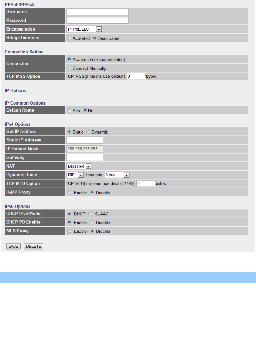
PPPoE/PPPoA
IP Common Options
Parameter
Description
User Name
Enter the username exactly as your ISP assigned.
Password
Enter the password that your ISP has assigned to you.
Encapsulation
Please check with your ISP the method of multiplexing.
In PPPoE/PPPoA mode, please select “PPPoE LLC”,
“PPPoE VC-Mux”, “PPPoA LLC”, or “PPPoA VC-Mux”.

40
Bridge Interface
This router has built-in ADSL modem and is able to
connect to ISP directly. Alternatively, if you want to use
the dial up software to manually connect to the ISP, you
have to activate the ”Bridge Interface”.
Connection
Always On – The connection will be kept always on. If
the connection is interrupted, the router will re-connect
automatically.
Connect On-Demand – Only connect when you want to
surf the Internet. “Close if idle for xx minutes” is set to
stop the connection when the network traffic is not
sending or receiving after an idle time.
Connect Manually – After you have selected this option,
please go to Status page. You will see the “Connect”
button, click it and the router will connect to the ISP. If
you want to stop the connection, please click
“Disconnect” button.
TCP MSS Option
The “TCP MSS Option” enables the configuration of the
maximum segment size (MSS) for transient packets that
traverse a router, specifically TCP segments in the SYN
bit set, when PPPoE is being used in the network. Please
specify the MSS range from 100 to 1452 bytes or 0 byte
as the default value.
Default Route
When “Default Router” is enabled, all the packets for
destinations not known by the router's routing table are
sent to the default route. By default, it is enabled.
Get IP Address
Choose Static or Dynamic IP Address. If Static IP is
selected, please set the IP Address, Subnet Mask and
Gateway obtained from your ISP.

41
Static IP Address
Enter the IP Address assigned by your ISP. Only if you
chose Static above.
IP Subnet Mask
Enter the Subnet Mask assigned by your ISP. Only if you
chose Static above.
Gateway
Enter the Gateway assigned by your ISP. Only if you
chose Static above.
NAT
NAT (Network Address Translation), an Internet standard
that enables a local-area network (LAN) to use one set of
IP addresses for internal traffic and a second set of
addresses for external traffic. When NAT is enabled, the
router will help to make all necessary IP address
translations for the PC connected to the router to access
the Internet.
Dynamic Route
Dynamic routing allows routing tables in routers to
change as the possible routes change. This router
supports RIP1, RIP2-B and RIP2-M protocols for
dynamic routing. After the RIP protocol is selected,
please choose the RIP direction from “None”, “Both”, “IN
Only” or “OUT Only”.
TCP MTU Option
MTU (Maximum Transmission Unit) determine the
maximum size of each packet in any transmission within
the network. Please specify the MTU range from 100 to
1500 bytes or 0 byte as the default value.
IGMP Porxy
Enable or disable IGMP proxy feature.
IPv4 Options
Parameter
Description
Get IP Address
Choose Static or Dynamic IP Address. If Static IP is

42
selected, please set the IP Address, Subnet Mask and
Gateway obtained from your ISP.
Static IP Address
Enter the IP Address assigned by your ISP. Only if you
chose Static above.
IP Subnet Mask
Enter the Subnet Mask assigned by your ISP. Only if you
chose Static above.
Gateway
Enter the Gateway assigned by your ISP. Only if you
chose Static above.
NAT
NAT (Network Address Translation), an Internet standard
that enables a local-area network (LAN) to use one set of
IP addresses for internal traffic and a second set of
addresses for external traffic. When NAT is enabled, the
router will help to make all necessary IP address
translations for the PC connected to the router to access
the Internet.
Dynamic Route
Dynamic routing allows routing tables in routers to
change as the possible routes change. This router
supports RIP1, RIP2-B and RIP2-M protocols for
dynamic routing. After the RIP protocol is selected,
please choose the RIP direction from “None”, “Both”, “IN
Only” or “OUT Only”.
TCP MTU Option
MTU (Maximum Transmission Unit) determine the
maximum size of each packet in any transmission within
the network. Please specify the MTU range from 100 to
1500 bytes or 0 byte as the default value.
IGMP Porxy
Enable or disable IGMP proxy feature.
IPv6 Options
43
Parameter
Description
DHCP IPv6 Mode
Choose DHCPv6 or (Stateless address
autoconfiguration)SLAAC mode for IPv6
DHCP PD Enable
Enable or disable Prefix Delegation(PD) function of
DHCPv6
MLD Proxy
Enable or disable MLD proxy feature.
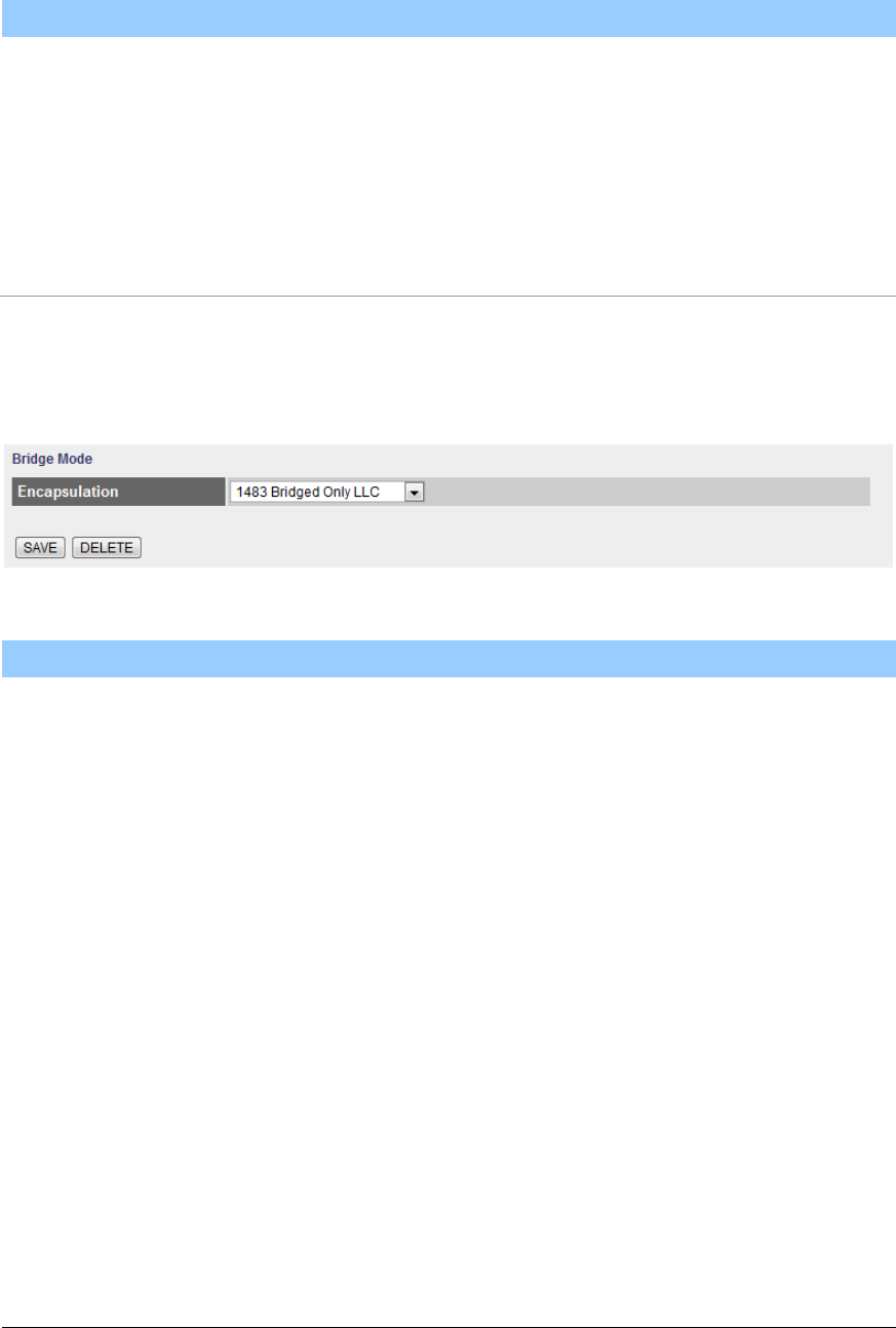
Bridge Mode
Bridge Mode
Parameter
Description
Encapsulation
Please check with your ISP the method of multiplexing.
In Bridge Mode, please select “1483 Bridge IP Only LLC”
or “1483 Bridge IP Only VC-Mux”.
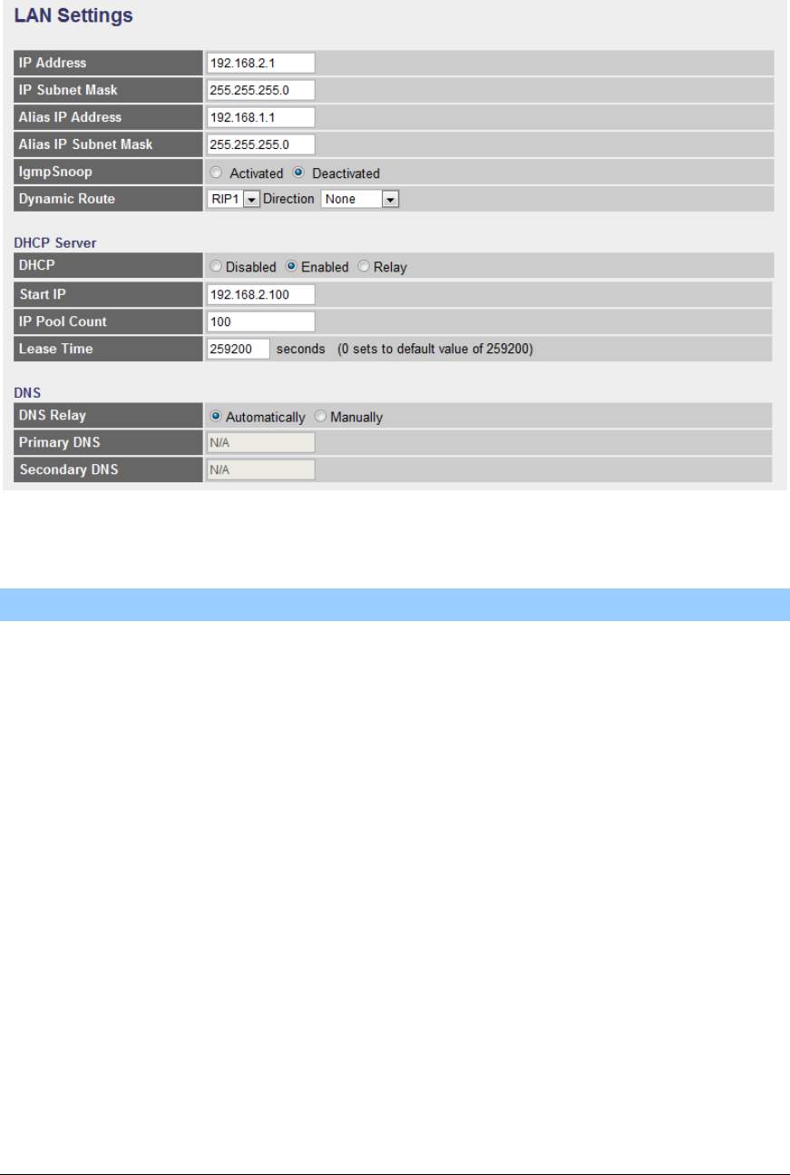
5.2.1.2. LAN
This page is used to configure the LAN interface of your ADSL Router. You can
set IP address, subnet mask, DHCP Server and IPv6 Settings.
44
LAN Settings
Parameter
Description
IP Address
Enter the IP Address of the ADSL router for the local
user to access the router’s web page. By default, the IP
Address is 192.168.2.1.
IP Subnet Mask
Enter the Subnet Mask of the ADSL router. By default,
the Subnet Mask is 255.255.255.0.
Alias IP Address
Alias IP allows you to partition a physical network into
logical networks over the same Ethernet interface.
Enter the Alias IP Address of the ADSL router for the
local user to access the router’s web page. By default,
the IP Address is 192.168.1.1.
Alias IP Subnet Mask
Enter the Alias IP Subnet Mask of the ADSL router. By
default, the Subnet Mask is 255.255.255.0.
IGMP Snoop
When “IGMP Snoop” (Internet Group Management
Protocol Snoop) is enabled, the router can make

45
intelligent multicast forwarding decisions by examining
the contents of each frame’s IP header. Without the
function, the router will broadcast the multicast packets to
each port and may create excessive traffic on the
network and degrade the performance of the network.
Dynamic Route
Dynamic routing allows routing tables in routers to
change as the possible routes change. This router
supports RIP1, RIP2-B and RIP2-M protocols for
dynamic routing. After the RIP protocol is selected,
please choose the RIP direction from “None”, “Both”, “IN
Only” or “OUT Only”.
DHCP
Select whether DHCP is Disabled, Enabled or Relay.
Start IP
If the DHCP Server is enabled, please set the “Starting
IP Address” which will be the first IP Address assigned to
the LAN client. By default, the “Starting IP Address” is
192.168.2.100.
IP Pool Count
You can select a particular IP address range for your
DHCP server to issue IP addresses to your LAN Clients.
By default, the “IP Pool Count” is 100. The IP range is
starting from IP 192.168.2.100 to 192.168.2.199.
Lease Time
In the Lease Time setting you can specify the time period
that the DHCP Server lends an IP address to your LAN
clients. The DHCP will change your LAN client’s IP
address when this time threshold period is terminated.
DNS Relay
A Domain Name System (DNS) server is like an index of
IP addresses and Web addresses. If you type a Web
address into your browser, such as “www.router.com”, a
DNS server will find that name in its index and the
matching IP address. Please select “Use Auto
46
Discovered DNS Server Only” to auto set the DNS
Server. If there is a DNS server that you would rather to
use, please select “Use Discovered DNS Server Only”
and you need to specify the IP address of that DNS
server.
Primary DNS
Enter the ISP’s DNS Server IP Address; or you can
specify your own preferred DNS Server IP Address.
Secondary DNS
This is optional. You can enter another DNS Server’s IP
Address as a backup. The secondary DNS will be used
should the Primary DNS fail.
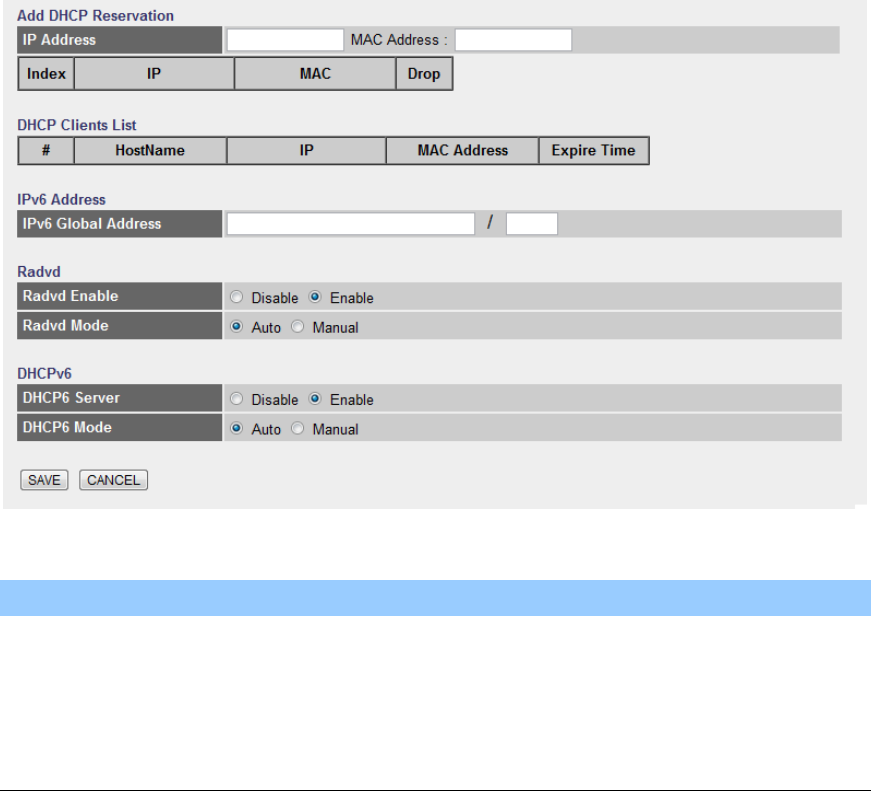
Add DHCP Reservation
Parameter
Description
IP Address
Set reserve IP Address for DHCP server
MAC Address
Set reserve MAC Address for DHCP server
47
DHCP Clients List
Show clients list which released by DHCP server
IPv6 Global Address
Set a IPv6 Global Address for LAN interface (?)
Radvd Enable
Enable or Disable Radvd
Radvd Mode
Choose Auto or Manual mode for Radvd. For Manual
mode, you can set parameters of Radvd manually, like
the prefix, the length of prefix, etc. For Auto mode,
system will set default parameters for Radvd
DHCP6 Server
You can enable or disable the DHCP6 server. By
enabling the DHCP6 server the router will automatically
give your LAN clients an IPv6 address. If the DHCP is
not enabled then you’ll have to manually set your LAN
client’s IPv6 addresses.
DHCP6 Mode
Toggle DHCP Mode (Auto or Manual)
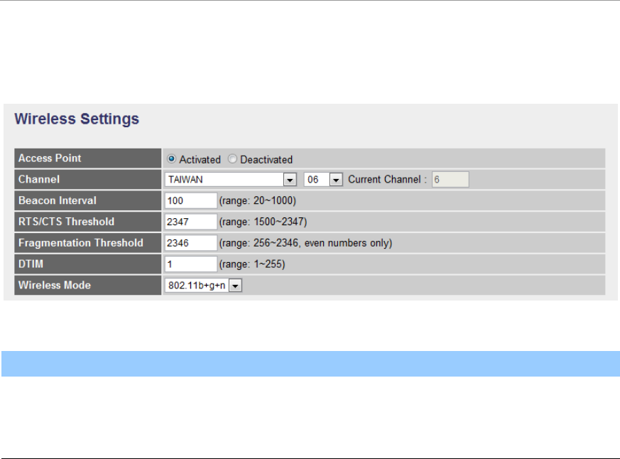
5.2.1.3. Wireless
Wireless Settings
Parameter
Description
Access Point
Activated or deactivated the wireless function of the
router. When it is activated, the router will be an access
point for other wireless clients to connect wirelessly.

48
Channel
It is the radio channel used by the wireless LAN. All
devices in the same wireless LAN should use the same
channel. Please select the country you are located and
designate a channel that the router will use. For product
available in the USA/Canada market, only channel 1~11
can be operated. For product available in Europe market,
only channel 1~13 can be operated. Selection of other
channels is not permitted. If you want to let the router
automatically to find an available channel with the
highest signal strength, please select “Auto”. The auto-
selective channel will be shown in the “Current Channel”
field.
Beacon Interval
The interval of time that this wireless router broadcast a
beacon. Beacon is used to synchronize the wireless
network. The range for the beacon period is between 20
and 1000 with a typical value of 100 (milliseconds).
RTS/CTS Threshold
When the packet size is smaller than the RTS threshold,
the wireless router will not use the RTS/CTS mechanism
to send this packet. The range is from 1500 to 2347.
Fragmentation
Threshold
Fragment Threshold specifies the maximum size of
packet during the fragmentation of data to be transmitted.
If you set this value too low, it will result in bad
performance. Enter a value from 256 to 2346.
DTIM
Determines the interval the Access Point will send its
broadcast traffic. The range is from 1 to 255 and the
default value is 3 beacons.
Wireless Mode
802.11b – It only allows 802.11b wireless network client
to connect this router (maximum transfer rate 11Mbps).
49
802.11g – It only allows 802.11g wireless network client
to connect this router (maximum transfer rate 54Mbps).
802.11b+g – It only allows 802.11b and 802.11g wireless
network client to connect this router (maximum transfer
rate 11Mbps for 802.11b clients, and maximum 54Mbps
for 802.11g clients).
802.11n – It only allows 802.11n wireless network client
to connect this router (maximum transfer rate 300Mbps).
802.11g+n – It allows 802.11g, and 802.11n wireless
network client to connect this router (maximum transfer
rate 54Mbps for 802.11g clients, and maximum 300Mbps
for 802.11n clients).
802.11b+g+n – It allows 802.11b, 802.11g, and 802.11n
wireless network client to connect this router (maximum
transfer rate 11Mbps for 802.11b clients, maximum
54Mbps for 802.11g clients, and maximum 300Mbps for
802.11n clients).
NOTE: For 802.11b and 802.11g mode, the signals can
be transmitted only by antenna 1 (The antenna in the
right side of the rear panel).
For 802.11n mode: The router is operating in a 2T2R
Spatial Multiplexing MIMO configuration. 2 antennas are
for signal transmitting and 2 antennas are for signal
receiving.
50
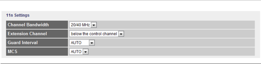
11n Settings
Parameter
Description
Channel Bandwidth
Set channel width of wireless radio. Do not modify
default value if you don’t know what it is, default
setting is ‘20/40 MHz’.
Extension Channel
Select the extension channel to above or below the
control channel while 40MHz channel bandwidth is
selected. Do not modify the default value if you don’t
know what it is.
Guard Interval
It is one of several draft-n features designed to improve
efficiency. Select 400nsec to provide a shorter delay
between transmission frames in 11n network. The
throughput in 400nec guard interval is better than
800nsec guard interval.
MCS
Select MCS 0-15 to configure the data rate of 11n
network. When MCS 15 is selected, the data rate is up to
300Mbps. It is recommended to set “Auto” and the router
will negotiate with wireless clients to operate in a proper
data rate.
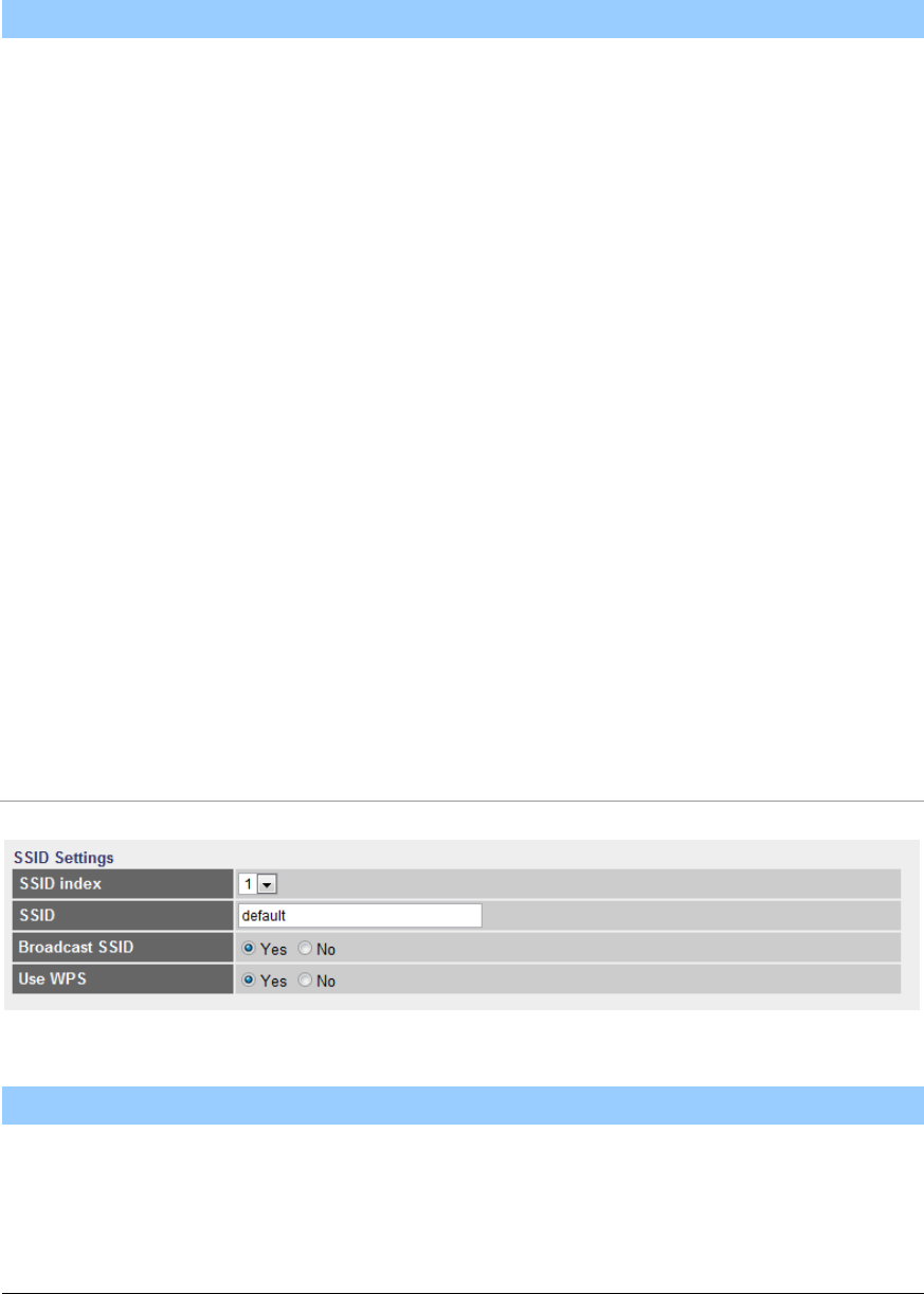
SSIDs Settings
Parameter
Description
SSID Index
This router can support multiple SSIDs. By default, this
function is disabled. You can only set a set of SSID.
SSID
The SSID (up to 32 printable ASCII characters) is the
51
unique name identified in a WLAN. The ID prevents the
unintentional merging of two co-located WLANs. The
default SSID of the router is “default”.
Broadcast SSID
Select “Yes” to make the SSID to be visible so wireless
clients can scan the router within the network. Select
“No” if you want to hide the SSID of the router. Wireless
clients have to set the same SSID of the router in order
to access the network.
Use WPS
Select “Yes” to enable WPS function, Select “No” to
disable WPS.
WPS Settings
Wi-Fi Protected Setup (WPS) is the simplest way to build connection between
wireless network clients and this router. You don’t have to select encryption
mode and input a long encryption passphrase every time when you need to setup
a wireless client, you only have to press a button on wireless client and this
wireless router, and the WPS will do the setup for you.
This router supports two types of WPS: Push-Button Configuration (PBC), and
PIN code. If you want to use PBC, you have to switch this wireless router to WPS
mode and push a specific button on the wireless client to start WPS mode. You
can push Reset/WPS button of this router, or select “PBC” and click “Start WPS”
button in the WPS setup page to do this. If you want to use PIN code, you have
to know the PIN code of wireless client and switch it to WPS mode, then set the

52
PIN code of the wireless client you wish to connect to this router in the WPS
setup page and click “Start WPS” button to start WPS mode.
Parameter
Description
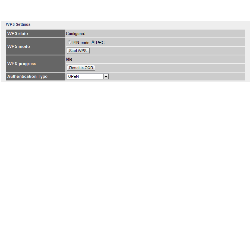
WPS state
If the wireless security (encryption) function of this
wireless router is enabled, you’ll see ”Configured”
message here. If wireless security function has not been
set, you’ll see ‘”Unconfigured”.
WPS mode
When PIN code is selected, you have to enter the 8-digit
PIN code of the wireless client you wish to connect to this
router. If PBC mode is selected, just click “Start WPS”
button to start WPS mode.
Authentication Type
It’s very important to set wireless security settings
properly. If you don’t, hackers and malicious users can
reach your network and valuable data without your
consent and this will cause serious security problem.
This router supports WEP, WPA-PSK and WPA2-PSK
authentication type. If the router has enabled the
authentication, all the wireless clients’ settings have to be
consistent with the router for building the connection.
WEP/WPA-PSK/WPA2-PSK and WPA-PSK/WPA2-PSK
Parameter
Description
WEP-64Bits
WEP is less level of security than WPA. WEP supports
64-bit and 128-bit key lengths to encrypt the wireless
data. The longer key length will provide higher security.
When “WEP-64Bits” is selected, you have to enter
exactly 5 ASCII characters (“a-z” and “0-9”) or 10
hexadecimal digits ("0-9", "a-f") for each Key (1-4).
WEP-128Bits
When “WEP-128Bits” is selected, you have to enter
exactly 13 ASCII characters (“a-z” and “0-9”) or 26
hexadecimal digits ("0-9", "a-f") for each Key (1-4).
53
WPA-PSK
WPA-PSK is suitable for home and small business. It
uses TKIP or AES for data encryption. When “WPA-PSK”
is selected, please select the encryption method and
enter 8-63 ASCII characters or 64 hexadecimal
characters as the “Pre-Shared Key”.
WPA2-PSK
WPA2-PSK is also for home and small business. It uses
TKIP or AES for data encryption. WPA2-PSK offers the
highest level of security available. When “WPA2-PSK” is
selected, please select the encryption method and enter
8-63 ASCII characters or 64 hexadecimal characters as
the “Pre-Shared Key”.
WPA-PSK/ WPA2-PSK
When “WPA-PSK/WPA2-PSK” is selected, please select
the encryption method (TKIP or AES) and enter 8-63
ASCII characters or 64 hexadecimal characters as the
“Pre-Shared Key”.
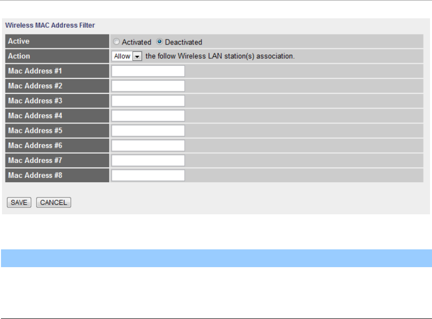
Wireless MAC Address Filter
Parameter
Description
Active
This router can prevent the wireless clients from
accessing the wireless network by checking the MAC

54
Address of the clients. If you enable this function, please
set the MAC Address of the wireless clients that you
want to filter.
Action
Allow Association – Only allow the wireless clients with
the MAC Address you have specified can access to the
router.
Deny Association – The wireless clients with the MAC
Address you have specified will be denied accessing to
the router.
Mac Address #1-8
Please enter the MAC Address of the wireless clients for
the filtering control.
55
5.2.2. Advanced Setup
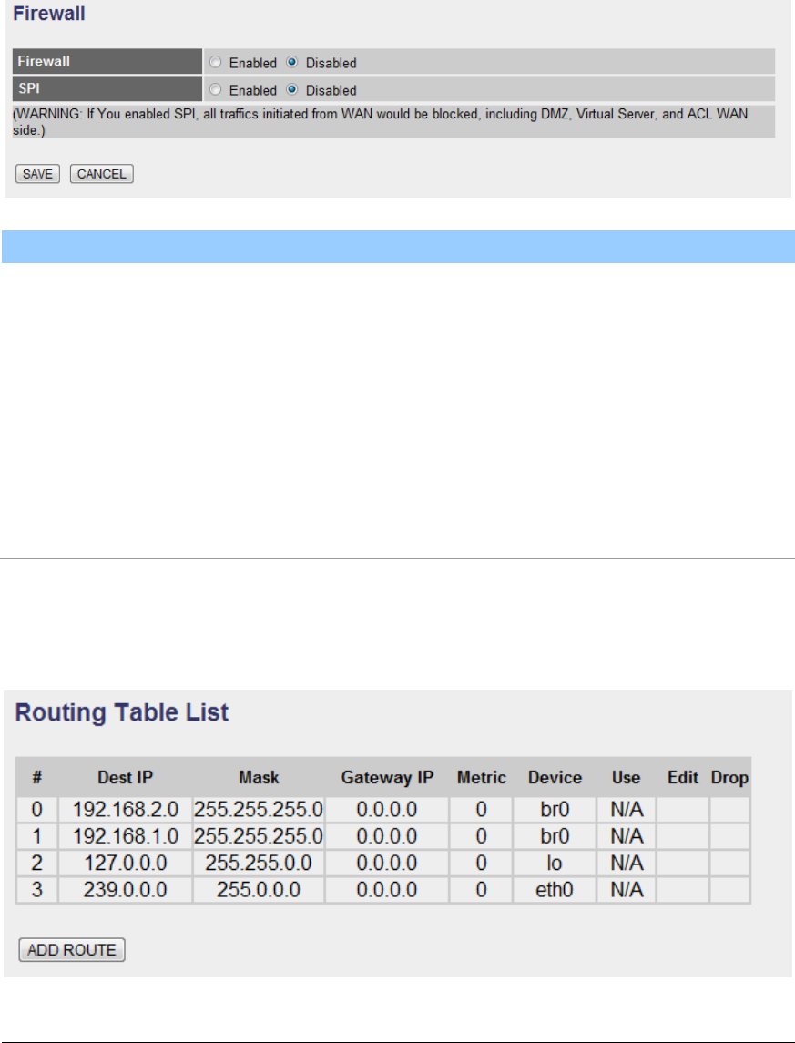
5.2.2.1. Firewall
Parameter
Description
Firewall
When you enable the firewall function, it will protect you
from following attacks of WAN side:
SYN flooding attack
Ping of Death
Teardrop
Land attack
SPI
If you enable SPI, all traffics initiated from WAN site will
be blocked including DMZ, Virtual Server, etc.
5.2.2.2. Routing

56
Routing Table List
You can see the current routing table of the router here. If you want to add
another routing rule, please click “ADD ROUTE”.
Parameter
Description
Dest IP
Show the IP Address of the destination LAN.
Mask
Show the Subnet Mask of the destination LAN. If it shows
“8” that means the Subnet Mask is “255.0.0.0”; “16”
means the Subnet Mask is “255.255.0.0”; “24” means the
Subnet Mask is “255.255.255.0”.
Gateway IP
The next stop gateway of the path toward the destination
LAN. This is the IP of the neighbor router that this router
should communicate with on the path to the destination
LAN.
Metric
The number of hops (routers) to pass through to reach
the destination LAN. It must be between 1 and 15.
Device
Show the interface that go to the next hop (router), such
as LAN port.
Use
The counter for access time.
Edit
Edit the route, this icon is not shown for system default
route.
Drop
Drop the route, this icon is not shown for system default
route.
Add Route
If you have another router with a LAN-to-LAN connection, you may need to
create a static routing on the router that is the gateway to Internet.
57
Parameter
Description
Destination IP Address
Enter the IP Address of the destination LAN.
IP Subnet Mask
Enter the Subnet Mask address of the destination LAN.
Gateway IP Address
This is the gateway IP Address where packets are sent.
Enter the gateway IP Address and select the channel
(PVC) you want to configure.
Metric
The number of hops (routers) to pass through to reach
the destination LAN. It must be between 1 and 15.
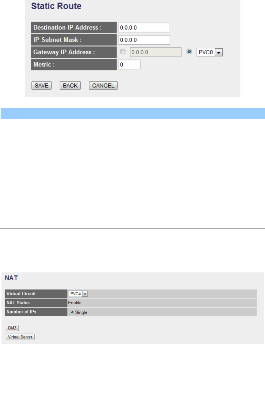
5.2.2.3. NAT
5.2.2.3.1. NAT
Network Address Translation (NAT) allows multiple users at your local site to
access the Internet through a single Public IP Address or multiple Public IP
58
Addresses. NAT provides Firewall protection from hacker attacks and has the
flexibility to allow you to map Private IP Addresses to Public IP Addresses for key
services such as Websites and FTP.
Parameter
Description
Virtual Circuit
Please select the channel (PVC) you want to configure.
NAT Status
The activated or deactivated status for the NAT function
will be shown here.
Number of IPs
Select “Single” if you only have a public IP Address.
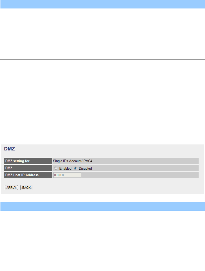
5.2.2.3.2. DMZ
The DMZ Host is a local computer exposed to the Internet. When setting a
particular internal IP Address as the DMZ Host, all incoming packets will be
checked by the firewall and NAT algorithms then passed to the DMZ Host.
For example, if you have a local client PC that cannot run an Internet application
(e.g. Games) properly from behind the NAT firewall, then you can open the client
up to unrestricted two-way Internet access by defining a DMZ Host.
Parameter
Description
DMZ setting for
Show the DMZ setting is for single or multiple IP
Addresses.
DMZ
Enable or disable the DMZ function.
DMZ Host IP Address
Enter a static IP Address to the DMZ Host. This IP
Address will be exposed to the Internet.
59
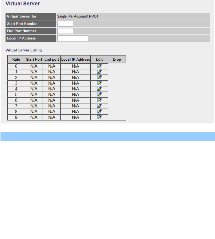
5.2.2.3.3. Virtual Server
Use the Virtual Server function when you want different servers/clients in your
LAN to handle different service/Internet application type (e.g. Email, FTP, Web
server etc.) from the Internet. Computers use numbers called port numbers to
recognize a particular service/Internet application type. The Virtual Server allows
you to re-direct a particular service port number (from the Internet/WAN) to a
particular LAN private IP Address and its service port number.
Parameter
Description
Virtual Server for
Show the Virtual Server setting is for single or multiple IP
Addresses.
Start Port Number
Enter the start port number.
End Port Number
Enter the end port number.
Local IP Address
It is recommended to enter a static IP Address for the
server here. If the server’s IP Address is obtained from
DHCP Server, the IP Address may be changed
60
dynamically and will cause problem on this feature.
Please assign a static IP Address to the server and make
sure that the IP Address is not in the range of IP
Addresses that the DHCP Server will assign.
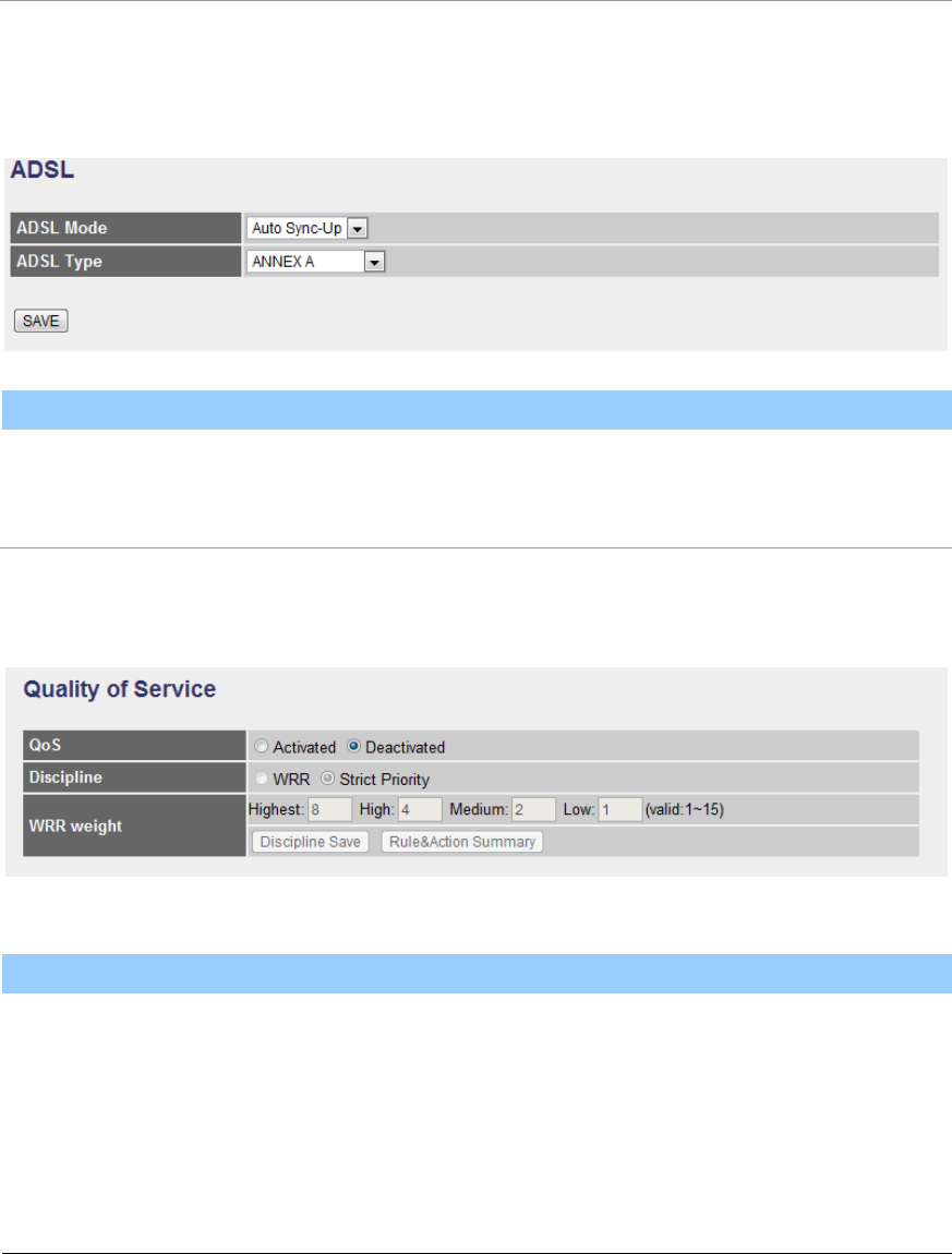
5.2.2.4. ADSL
Parameter
Description
ADSL Mode
Select the ADSL mode from the list.
ADSL Type
Select the ADSL type from the list.
5.2.2.5. QoS
Quality of Service
Parameter
Description
QoS
QoS can be toggled Activated and Deactivated. QoS
must be activated before you can edit the following
options.
Discipline
Toggle schedule discipline as WRR or Strict Priority.
61
WRR weight
Set WRR weight for 4 queues (highest, high, medium
and low) separately.
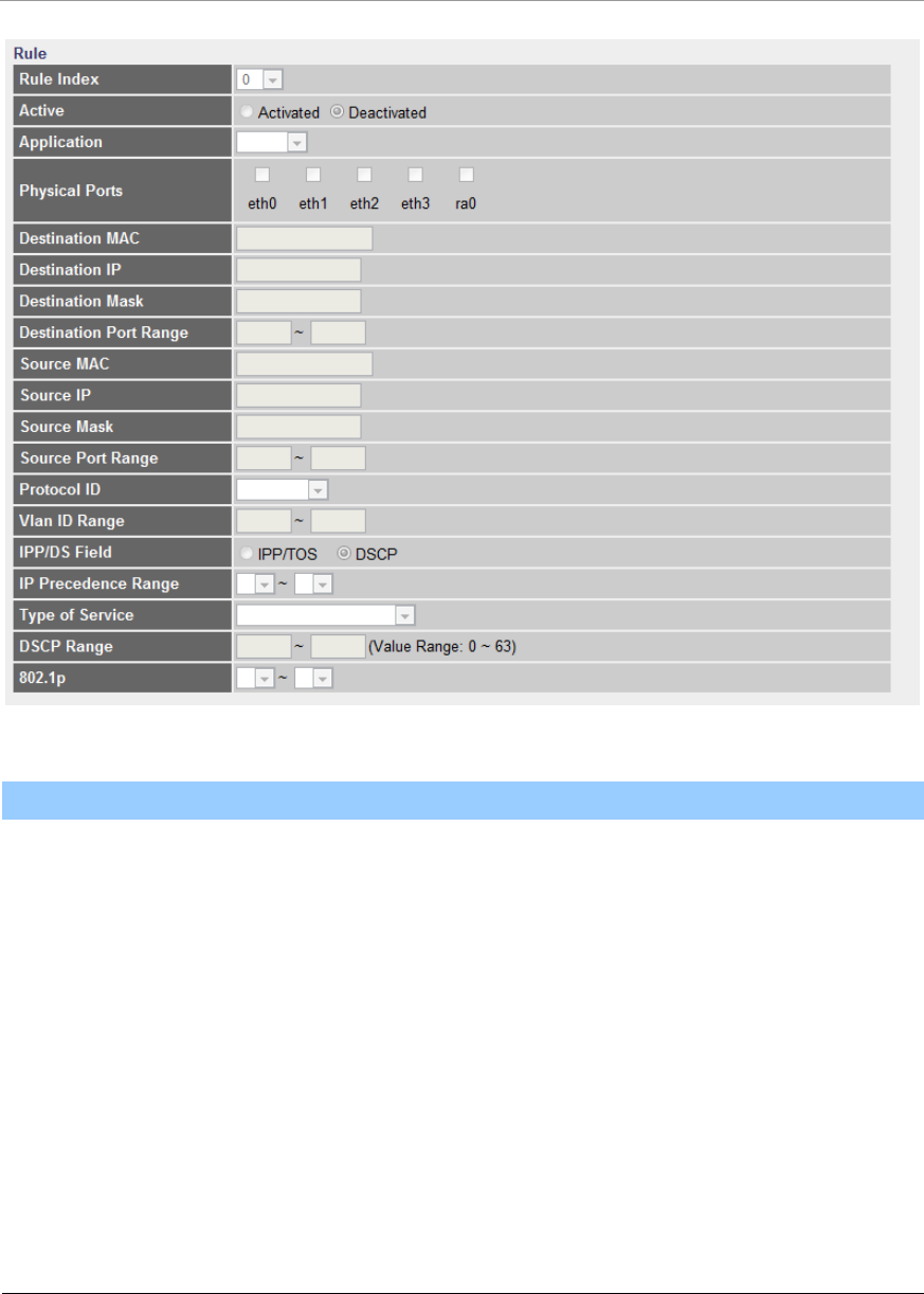
Rule
Parameter
Description
Rule Index
Select 16 different rules, each rule’s detail can be set and
saved
Active
Select Rule is activated or deactivated. There are 16
different rules, each rule can be activated or deactivated.
Application
Select 11 different applications: There are IGMP, SIP,
H.323, MGCP, SNMP, DNS, DHCP, RIP, RSTP, RTCP,
RTP.
Physical Ports
Once you select the application, the associated ports will
be displayed.

62
Destination MAC
Set the Ethernet MAC value that you want to filter in
destination side.
Destination IP
Set the IP address value that you want to filter in
destination side.
Destination Mask
Set the subnet mask value that you want to filter in
destination side.
Destination
Port Range
Set the port range value that you want to filter in
destination side.
Source MAC
Set the Ethernet MAC value that you want to filter in
source side.
Source IP
Set the IP address value that you want to filter in source
side.
Source Mask
Set the subnet mask value that you want to filter in
source side.
Source Port Range
Set the port range value that you want to filter in source
side.
Protocol ID
Select the protocol ID type that you want to filter.
Vlan ID Range
Set the Vlan value that you want to filter.
IPP/DS Field
Select IP QoS format.
IP Precedence Range
Select the IP precedence range.
Type of Service
Select 5 different type of service.
DSCP Range
Set the DSCP value that you want to filter
63
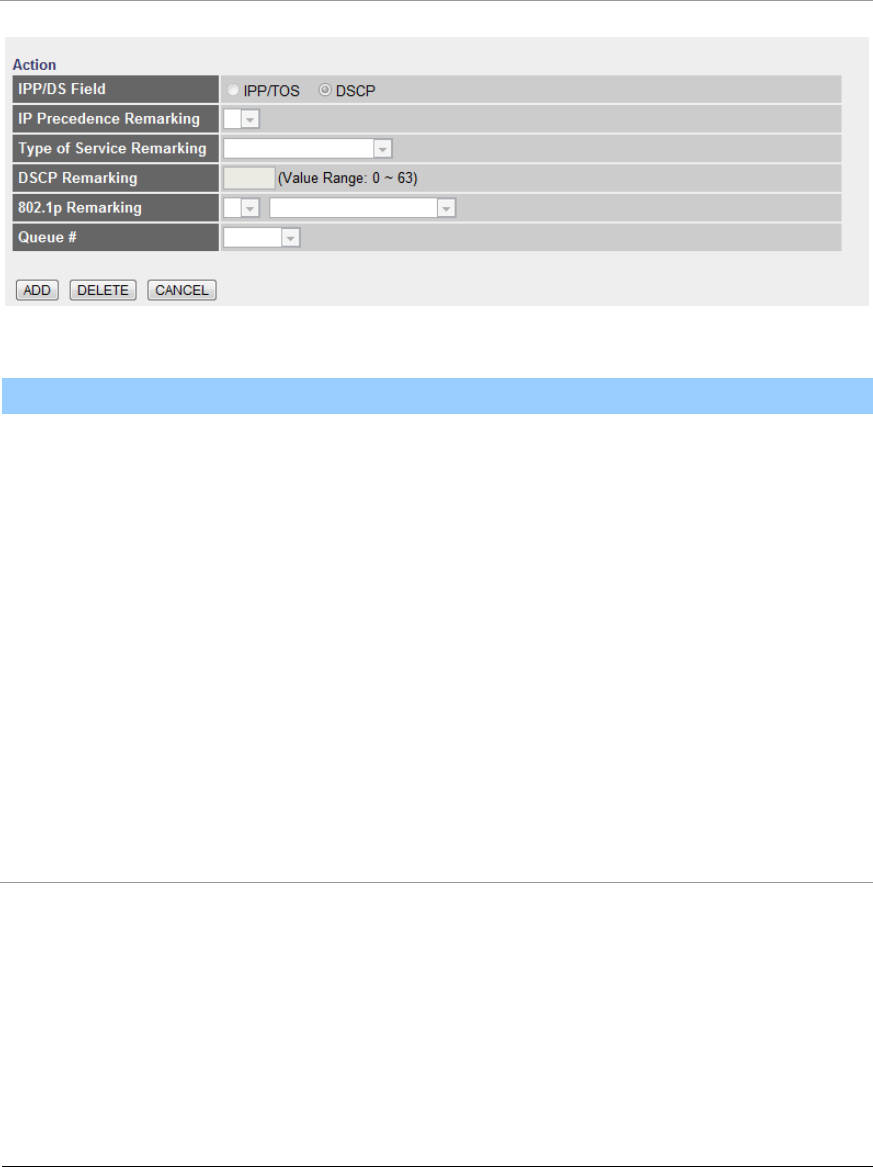
802.1p
Set the remarked new 802.1p priority value on the packet
that fulfill every
detail setting condition of each rule
Action
Parameter
Description
IPP/DS Field
Select IP QoS format.
IP Precedence
Remarking
Select the remarking value of IP precedence.
Type of Service
Remarking
Select the remarking value of type of service.
DSCP Remarking
Select the remarking value of DSCP.
802.1p Remarking
Select the remarking value of 802.1p.
Queue #
Select four types of Queue: Low, Medium, High, Highest.
5.2.2.6. PortBinding
64
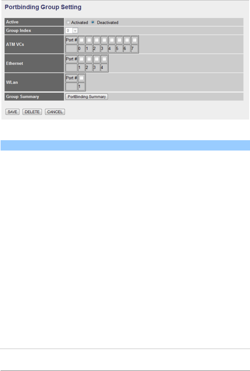
Portbinding Group Setting
Parameter
Description
Active
Toggle Activated or Deactivated Portbinding
Group Index
Select portbinding group index.
ATM VCs
Checking the Tagged and Port # boxes for each port
number will add a tag to let other devices know if they
need to check the packet and allow the packet through to
the port in question, respectively.
Ethernet
Checking the Tagged and Port # boxes for each port
number will add a tag to let other devices know if they
need to check the packet and allow the packet through to
the port in question, respectively.
WLan
Checking the Tagged and Port # box will add a tag to let
other devices know if they need to check the packet and
allow the packet through to the port in question,
respectively.
Group Summary
Press the button to display the summary of all
portbinding group. Show the summary of all Portbinding
Group rules.
65
5.2.3. Access Management
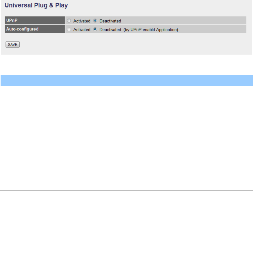
5.2.3.1. UPnP
When the UPnP function is enabled, the router can be detected by UPnP
compliant system such as Windows XP. The router will be displayed in the
Neighborhood of Windows XP, so you can directly double click the router or right
click the router and select “Invoke” to configure the router through web browser.
Universal Plug & Play
Parameter
Description
UPnP
Activated or deactivated the UPnP function.
Auto-configured
Select this check box to allow UPnP-enabled applications
to automatically configure the router so that they can
communicate through the router, for example by using
NAT traversal, UPnP applications automatically reserve a
NAT forwarding port in order to communicate with
another UPnP enabled device; this eliminates the need
to manually configure port forwarding for the UPnP
enabled application.
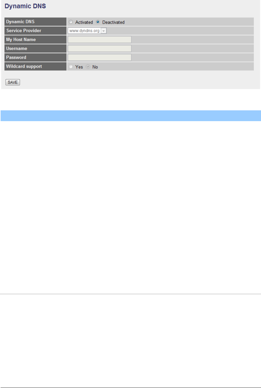
5.2.3.2. DDNS
DDNS allows you to map the static domain name to a dynamic IP address. You
must get an account, password and your static domain name from the DDNS
service providers.
66
Dynamic DNS
Parameter
Description
Dynamic DNS
Activated or deactivated the DDNS function.
Service Provider
This router supports DynDNS service provider.
My Host Name
Enter the domain name assigned to your router by the
service provider.
E-mail Address
Enter the E-mail address assigned by DDNS service
provider.
Username
Enter your username.
Password
Enter the password you set for the DDNS service.
Wildcard Support
Enable or disable the wildcard to stand for some
characters.
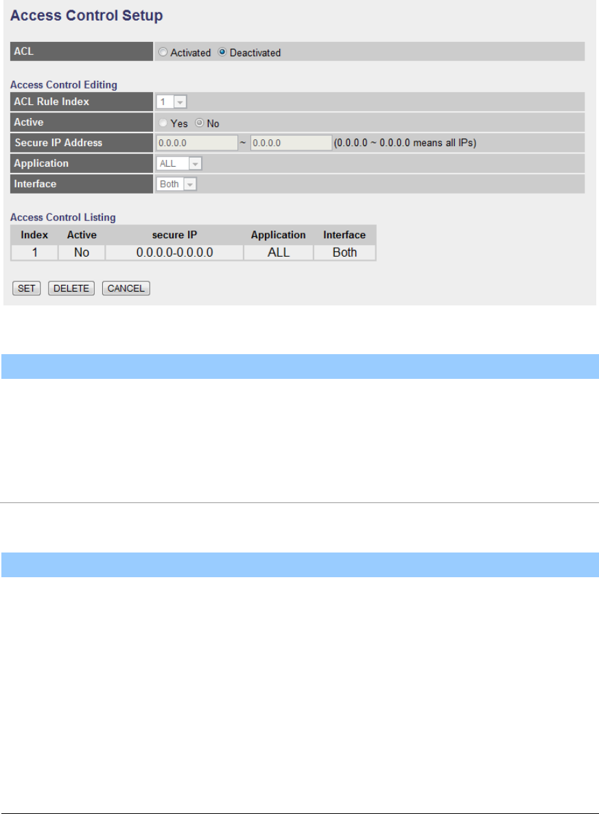
5.2.3.3. ACL
If you want to restrict users from accessing certain Internet applications/services
such as Internet websites, email, FTP etc., then this is the place to set that
configuration. Access Control allows users to define the traffic type permitted in
67
your LAN or WAN. You can control which computer can have access to these
services by entering the IP Address of the computer.
ACL
Parameter
Description
ACL
Activate or deactivate the Access Control function. When
you have activated the function, please do make sure
that you have designated the available
applications/services or you will be denied to access all
the services.
Access Control Editing
Parameter
Description
ACL Rule Index
This is the item number to record the setting rule.
Active
Toggle the ACL rule on or off with Yes or No,
respectively.
Secure IP Address
The default 0.0.0.0~0.0.0.0 allows any user to use this
service to remotely manage the router. Type a range of
IP Addresses to authorize access to a number of users
with matching IP Addresses.
68
Application
Choose the services that you permit to use in your LAN
or WAN interface. These services include Web, FTP,
Telnet, SNMP and Ping.
Interface
Select the interface that the user is allowed to use
services through it. It includes LAN, WAN or Both.
Access Control Listing
Access Control Listing is a list of all the rules you have
set for access control.
When you are done making changes, click on SET to save your changes,
DELETE to delete the rule with the parameters you set or CANCEL to exit
without saving.
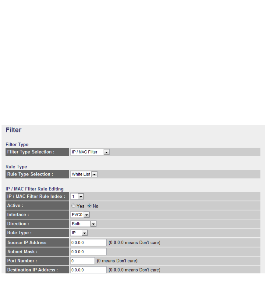
5.2.3.4. Filter
You can forbid some users accessing to the router by filtering the users through
IP Address or MAC Address. You can also restrict some applications or URLs be
accessing by users through the router here. Please select the Filter Type to start
configuring.
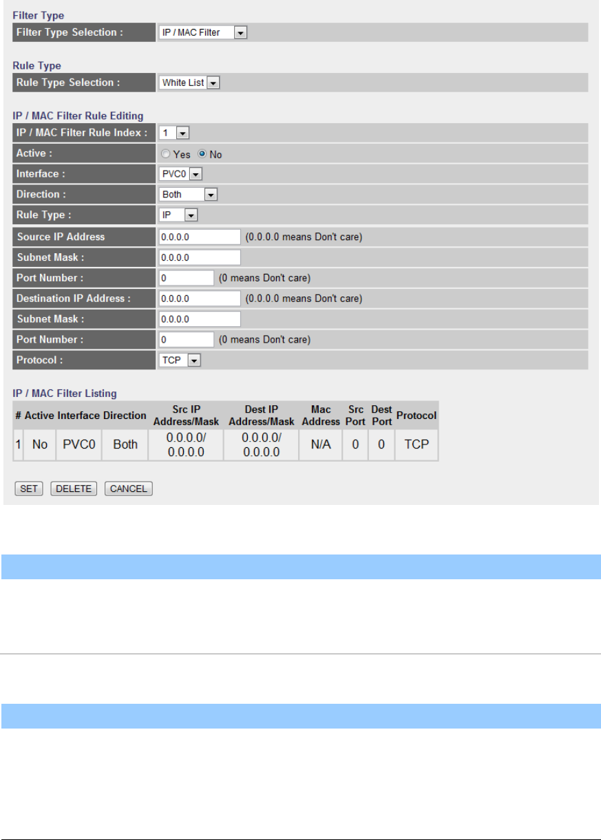
69
5.2.3.4.1. IP/MAC Filter
Rule Type
Parameter
Description
Rule Type Selection
Select the type of filter rule as White List or Black List. If
a packet matches the Black List rule, it will be dropped,
or matches the White List rule, it will be forwarded.
IP / MAC Filter Rule Editing
Parameter
Description
IP/MAC Filter Rule
Index
This is the item number to record the setting rule.
Active
Select “Yes” to enable the current rule, select “No” to

70
cancel the current rule.
Interface
Select which channel (PVC) to configure.
Direction
Select the access to the Internet (Outgoing) or from the
Internet (Incoming), or Both.
Rule Type
Select to filter through the IP Address or MAC Address.
Source IP Address
Enter the start IP Address which will be monitored. If
“0.0.0.0” is set, it means for any IP Address.
Subnet Mask
Enter the Subnet Mask based on the Source IP Address.
Port Number
LAN users use port number to distinguish one network
application over another such as 21 is for FTP service.
The port number range is from 0 to 65535. It is
recommended that this option be configured by an
advanced user.
Destination IP Address
Enter the start IP Address which will be monitored. If
“0.0.0.0” is set, it means for any IP Address.
Subnet Mask
Enter the Subnet Mask based on the Destination IP
Address.
Port Number
This is the port or port ranges that define the application.
Protocol
It is the packet protocol type used by the application.
Please select “TCP”, “UDP” or “ICMP”. For example, FTP
service, you have to select “TCP”.
IP / MAC Filter Listing
The IP/MAC Filter Listing will list the IP/MAC Filter rules
you have configured. You can review the settings here.
When you are done making changes, click on SET to save your changes,
71
DELETE to delete the rule with the parameters you set or CANCEL to exit
without saving.
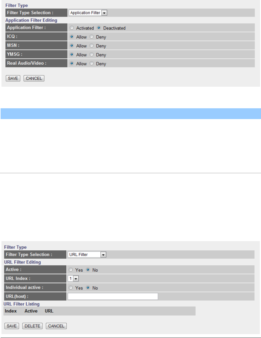
5.2.3.4.2. Application Filter
Application Filter Editing
Parameter
Description
Application Filter
Activate or deactivate the application filter.
ICQ/MSN/YMSG/Real
Audio/Video
If “Allow” is selected, the packets for these applications
will be able to pass through the router. If you want to
restrict these applications, please select “Deny”.
When you are done making changes, click on SAVE to save your changes,
DELETE to delete the rule with the parameters you set or CANCEL to exit
without saving.
5.2.3.4.3. URL Filter

72
URL Filter Editing
Parameter
Description
Active
Activate or deactivate the URL filter.
URL Index
This is the item number to record the setting.
Individual active
Activate or deactivate the selected individual URL filter
rule.
URL(host)
A URL can be thought of as the "address" of a web page
and is sometimes referred to informally as a "web
address." Please enter the web address here that you
want to restrict to be connected.
URL Filter Listing
The URL Filter Listing will list the URL you have
configured. You can review the settings here.
When you are done making changes, click on SAVE to save your changes,
DELETE to delete the rule with the parameters you set or CANCEL to exit
without saving.
73
5.3. Status
The status screens give you information about various aspects of your ADSL
router’s settings.
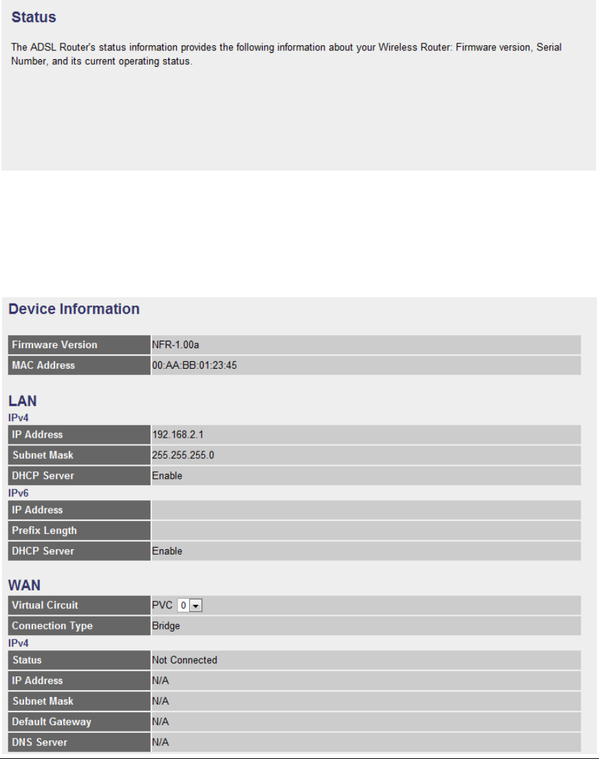
5.3.1. Device Info
In this page, you can know the device information including firmware, MAC
Address, LAN and WAN settings and also the ADSL line status.
74
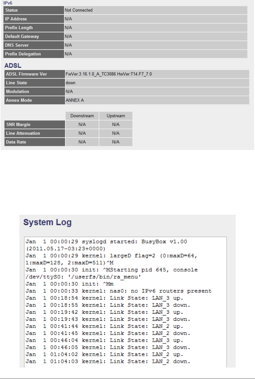
5.3.2. System Log
Display system logs accumulated up to the present time. You can also save the
logs for future reviewing.
75
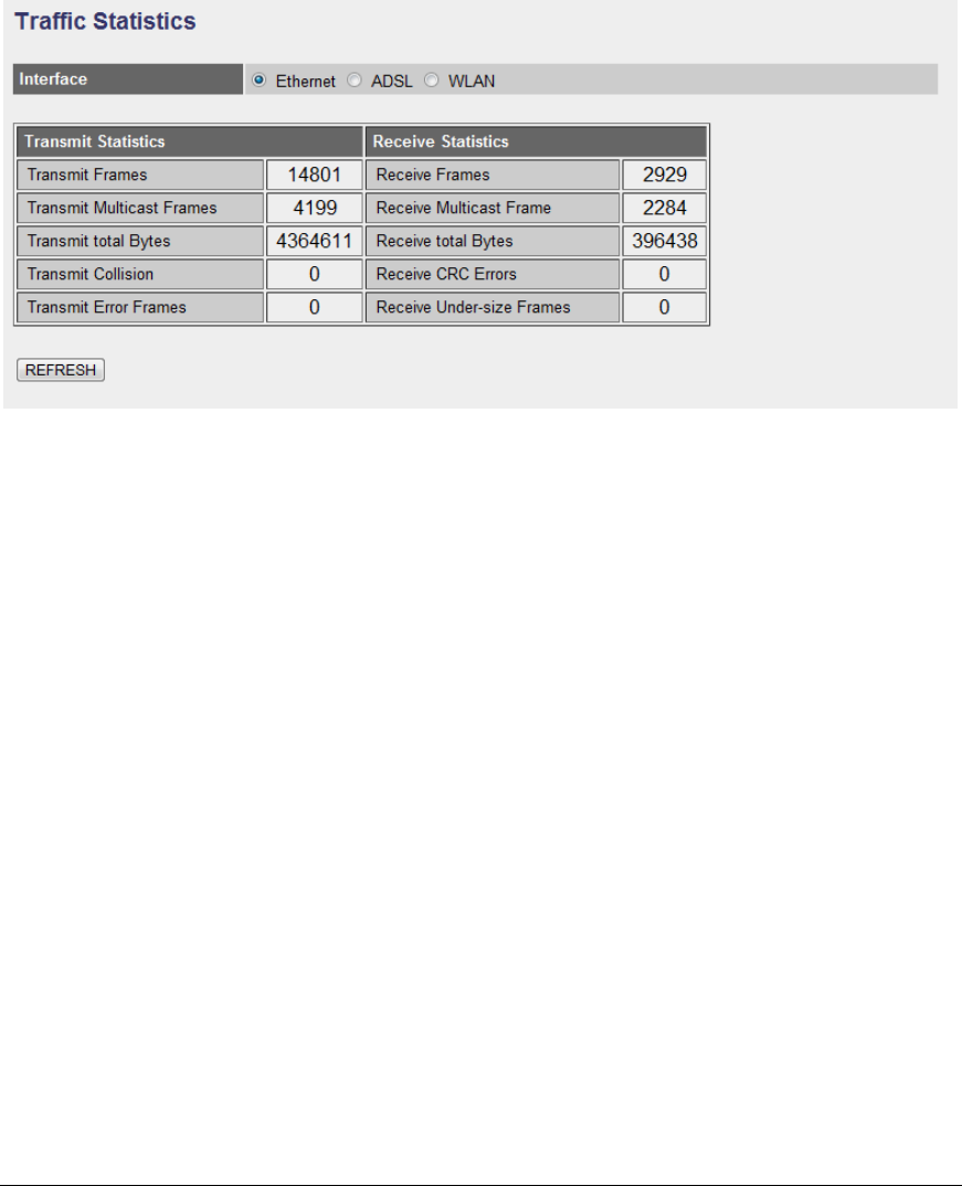
5.3.3. Statistics
Show the statistics of transmit and receive packets on the LAN port, ADSL line or
WLAN port.
76
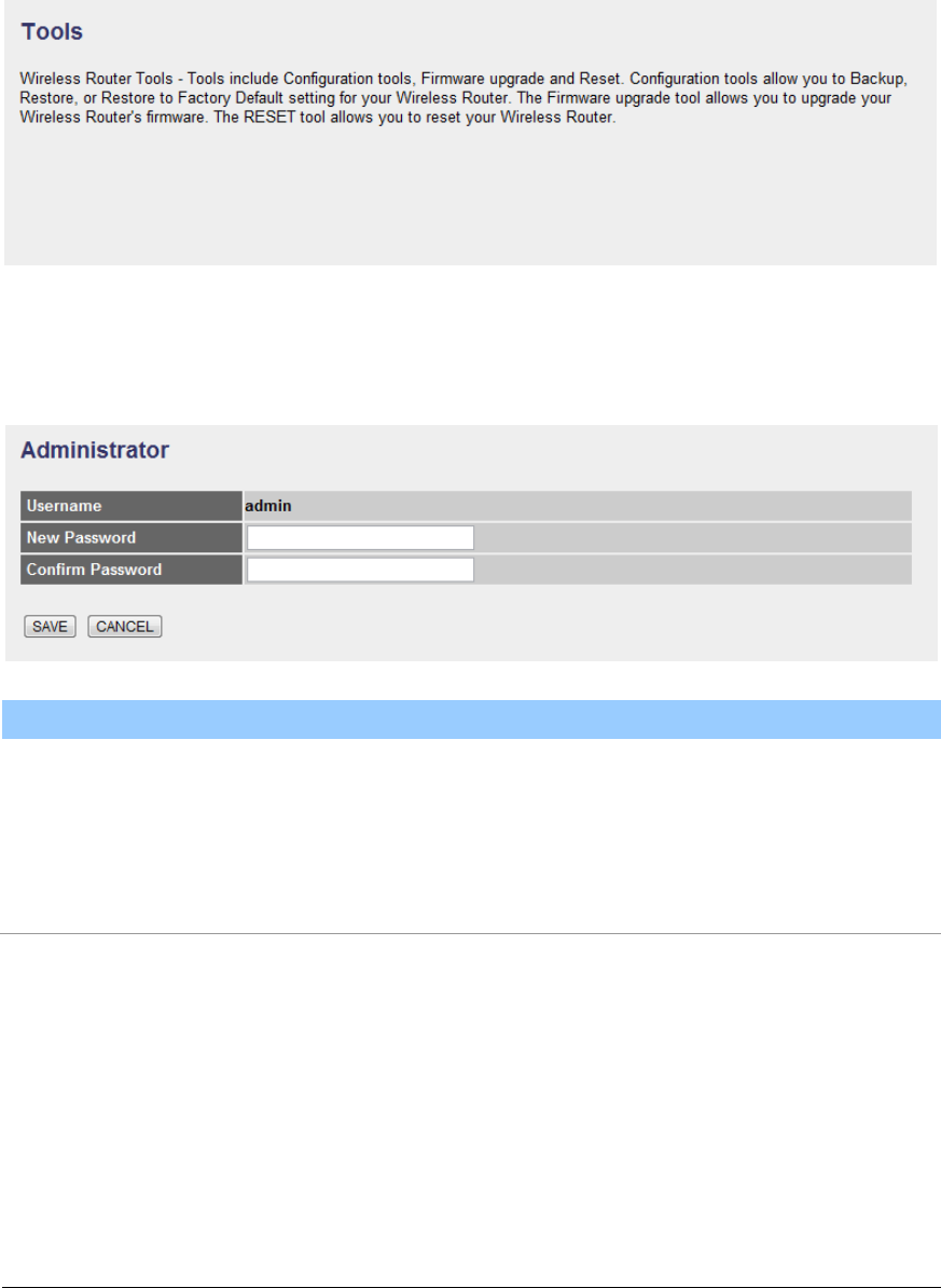
5.4. Tools
5.4.1. Administrator
Parameter
Description
Username
The username of the router is “admin” by default.
New Password
Enter up to 30-digit of the new password.
Confirm Password
Enter the new password again to confirm the setting.
When you are done making changes, click on SAVE to save your changes,
DELETE to delete the rule with the parameters you set or CANCEL to exit
without saving.
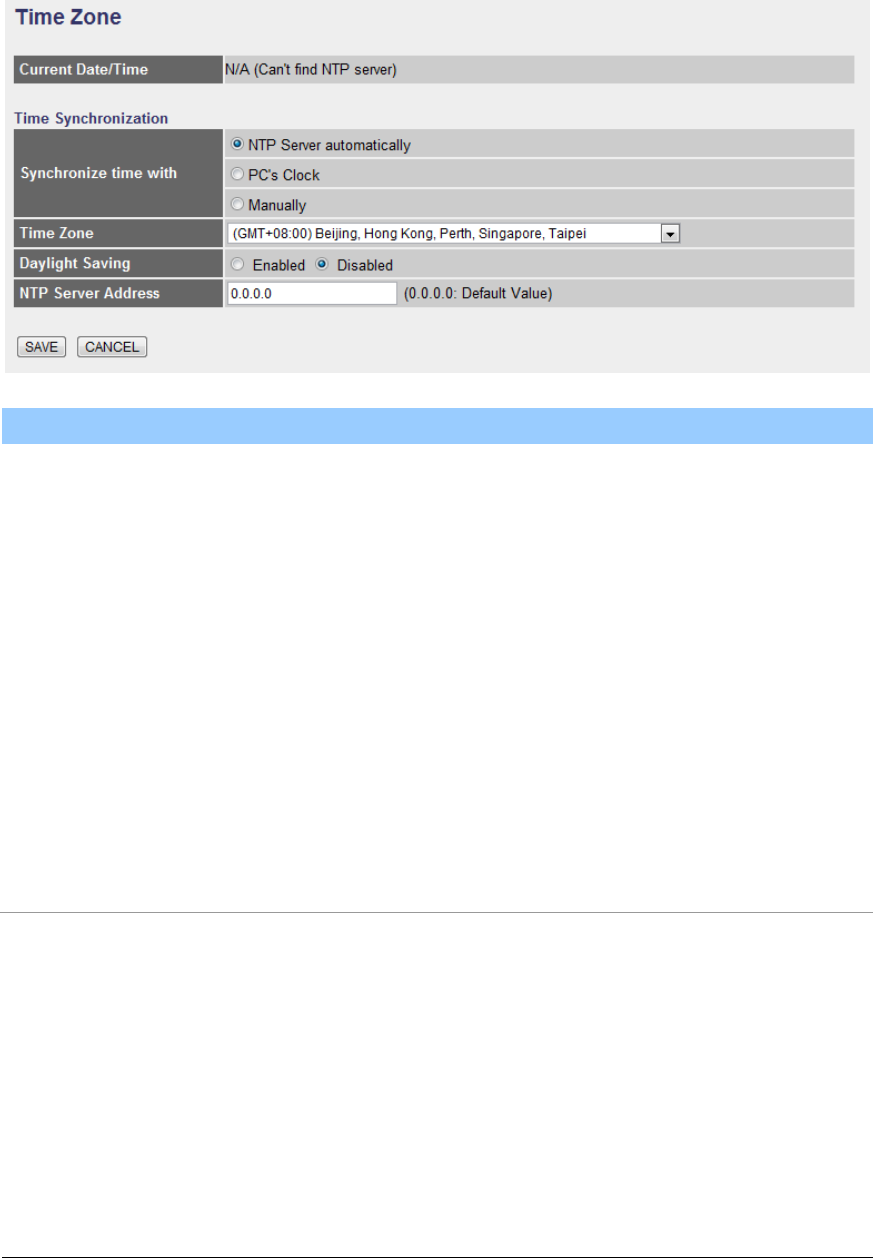
5.4.2. Time Zone
The Time Zone allows your router to set its time; this will affect function such as
System Log.
77
Parameter
Description
Current Date/Time
Show the current date/time of the router.
Synchronize time with
NTP Server Automatically – Set the time by following
with a NTP Server.
PC’s Clock – Set the time the same as your computer.
Manually – Set the time manually.
Time Zone
Select the time zone of the country you are currently in.
The router will set its time based on your selection.
Daylight Saving
Select this option if it is in daylight savings time.
NTP Server Address
Enter the IP Address of your time server.
When you are done making changes, click on SAVE to save your changes,
DELETE to delete the rule with the parameters you set or CANCEL to exit
without saving.
5.4.3. Firmware
If you have new firmware for some features update, please upgrade firmware of
the router here.
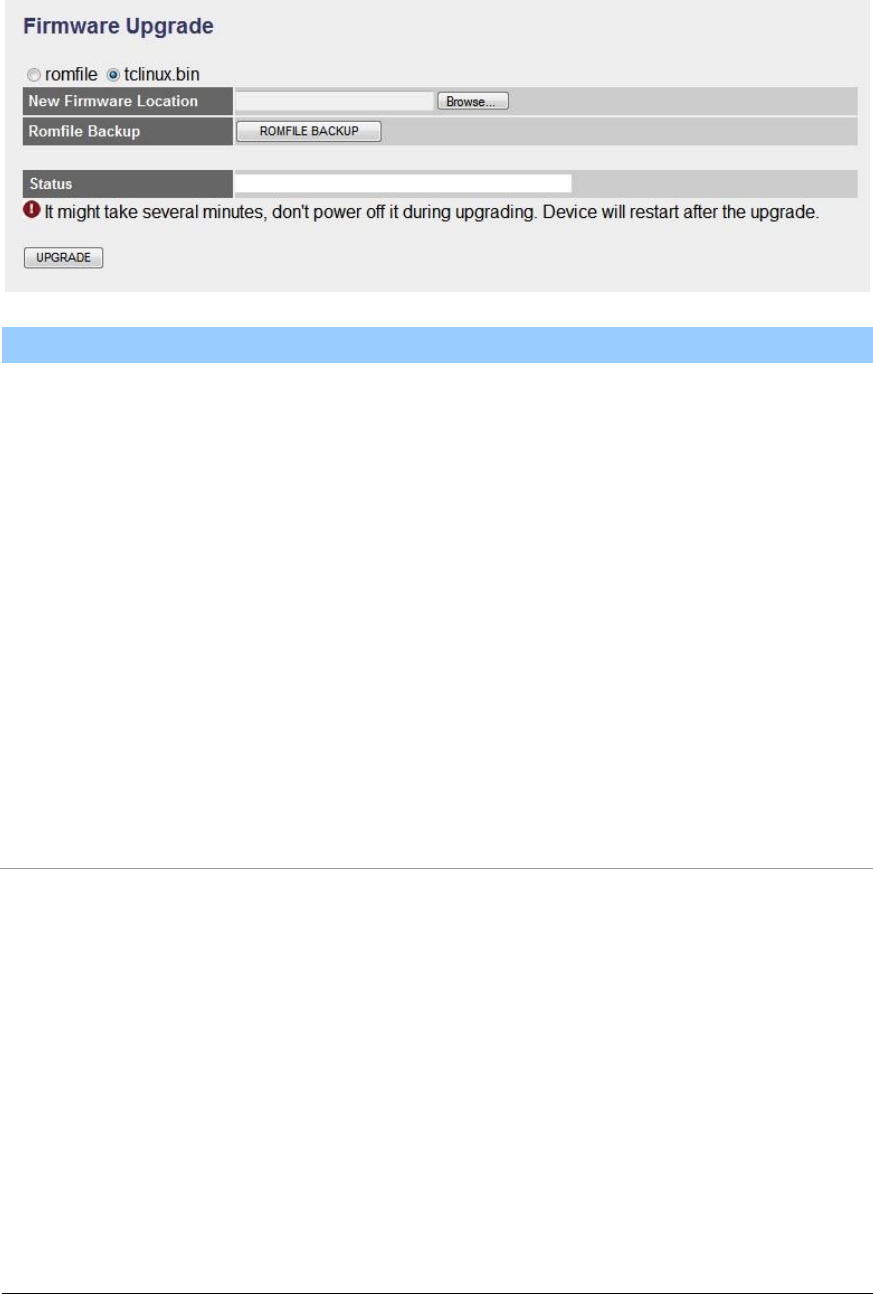
78
Parameter
Description
New Firmware
Location
Type in the location of the new firmware or click “Browse”
to find it.
Romfile Backup
To save the current settings as a backup file, please click
“ROMFILE SAVE”. Then please change the file name
and select the location you want to save the file.
Status
Show the upgrade status
Upgrade
Click “Upgrade” to begin the upgrade processes or
backup file restoring processes. After the router is
restarted, the processes are completed. It might take
several minutes, don't power off the router during
upgrading or restoring.
5.4.4. System Restart
In this page, you can restart your router or restore to factory defaults. If you wish
to restart the router using the factory default settings, select “Factory Default
Settings” to reset to factory defaults. You can also click the “Reset” button in the
rear panel of the router over 5 seconds to reset default settings.
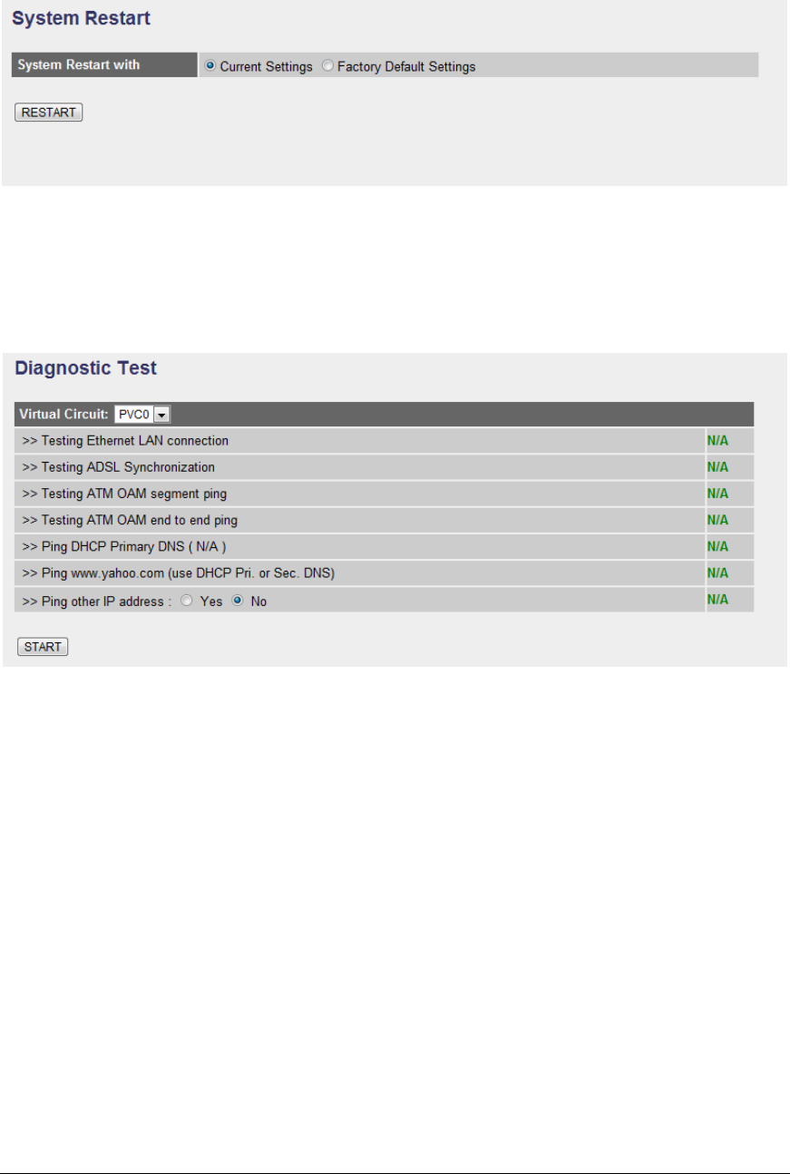
79
5.4.5. Diagnostics
This page allows you to diagnose the connectivity of the LAN and WAN network.

80
6. Troubleshooting
1. The LAN LED on the front panel does not light up.
STEPS
CORRECTIVE ACTION
1
Check the Ethernet cable connections between your ADSL2+
Router and the computer or hub.
2
Check for faulty Ethernet cables.
3
Make sure your computer’s Ethernet card is working properly.
4
If these steps fail to correct the problem, contact your local
distributor for assistance.
2. The ADSL LED on the front panel does not light up.
STEPS
CORRECTIVE ACTION
1
Check the telephone wire and connections between ADSL2+
Router DSL port and the wall jack.
2
Make sure that the telephone company has checked your phone
line and set it up for DSL service.
3
Reset your ADSL line to reinitialize your link to the DSLAM.
4
If these steps fail to correct the problem, contact your local
distributor for assistance.
3. I cannot access the web management.
STEPS
CORRECTIVE ACTION
1
Make sure you are using the correct IP address of ADSL2+
Router. Check the IP address of ADSL2+ Router.
2
Your computer and ADSL2+ Router’s IP addresses must be on
the same subnet for LAN access.
3
If you have changed ADSL2+ Router’s LAN IP address, then
enter the new one as the URL.
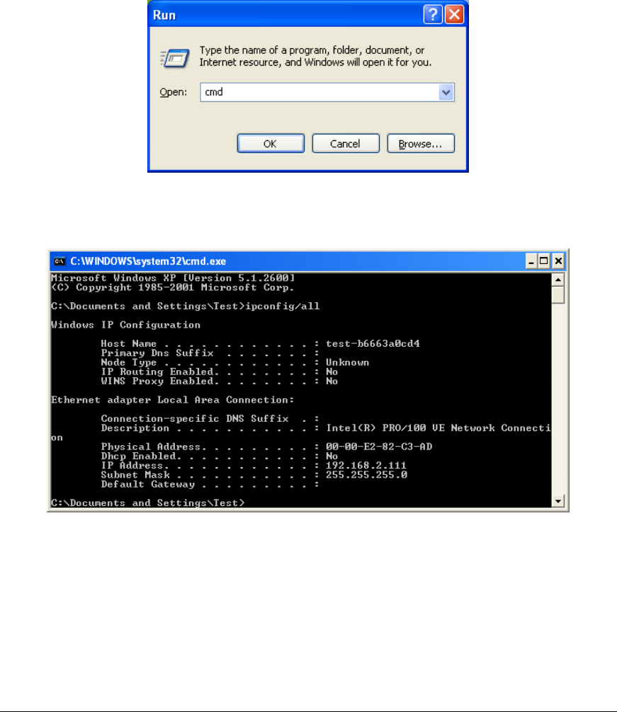
81
The following procedures will help you to check the current IP Address setting of
your computer. You can compare if your computer and router’s IP Addresses are
in the same subnet.
Step 1: Click “Start” and select “Run”.
Step 2: Type in “cmd” and click “OK”.
Step 3: Type ipconfig /all and click enter.
Your PC’s IP address is 192.168.2.111.
The PC’s Subnet Mask is 255.255.255.0.
Your PC’s MAC Address is the one entitled Physical Address (00-00-E2-82-
C3-AD).

82
4. I forget my login username and/or password.
STEPS
CORRECTIVE ACTION
1
If you have changed the password and have now forgotten it, you
will need to upload the default configuration file. This will erase all
custom configurations and restore all of the factory defaults
including the password.
2
Press the Reset button for five seconds, and then release it.
When the LAN LED begins to blink, the defaults have been
restored.
3
The default username is “admin”. The default password is “1234”.
The Password and Username fields are case-sensitive. Make
sure that you enter the correct password and username using the
proper casing.
4
It is highly recommended to change the default username and
password. Make sure you store the username and password in a
save place.
5. I cannot access the Web Management of the router after activating the ACL
function.
STEPS
CORRECTIVE ACTION
1
When ACL is activated, you have to set the ACL rule for allowing
some users to use some services. Check if you have set the
rules. If not, all the users are forbidden using any of service from
LAN or WAN.
2
If you cannot access the Web Management of the router, please
press the Reset button over 5 seconds to restore to defaults.
3
After the router is restarting, log in the router with the default IP
Address 192.168.2.1.

83
6. Initialization of the ADSL connection failed.
STEPS
CORRECTIVE ACTION
1
Check the cable connections between the ADSL port and the
wall jack. The ADSL LED on the rear panel of the router should
be on.
2
Check VPI, VCI, type of encapsulation and type of multiplexing
settings are the same as what you collected from your ISP.
3
Restart the router. If you still have problems, you may need to
verify your VPI, VCI, type of encapsulation and type of
multiplexing settings with the ISP.
7. I cannot get a WAN IP address from the ISP.
STEPS
CORRECTIVE ACTION
1
The ISP provides the WAN IP address after authenticating you.
Authentication may be through the user name and password, the
MAC address or the host name.
2
The username and password apply to PPPoE and PPoA
encapsulation only. Make sure that you have entered the correct
Service Type, User Name and Password (be sure to use the
correct casing).
8. Internet connection disconnects.
STEPS
CORRECTIVE ACTION
1
Check the schedule rules.
2
If you use PPPoA or PPPoE encapsulation, check the idle time-
out setting.
3
Contact your ISP.

84
7. Glossary
10Base-T
It is an Ethernet standard for Local Area Network (LAN). 10Base-T uses a twisted
pair cable with maximum length of 100 meters.
AAL
ATM Adaptation Layer that defines the rules governing segmentation and
reassembly of data into cells. Different AAL types are suited to different traffic
classes.
ADSL
Asymmetric Digital Subscriber Line, as its name showing, is an asymmetrical
data transmission technology with high traffic rate downstream and low traffic
rate upstream. ADSL technology satisfies the bandwidth requirement of
applications, which demand “asymmetric” traffic, such as web surfing, file
download and Video-on-demand (VOD).
ATM
Asynchronous Transfer Mode is a layer 2 protocol supporting high-speed
asynchronous data with advanced traffic management and quality of service
features.
bps
Bits per second, a standard measurement of digital transmission speeds.
Bridge
A device that connects two or more physical networks and forwards packets
between them. Bridges can usually be made to filter packets, that is, to forward
only certain traffic. Related devices are: repeaters which simply forward electrical
signals from one cable to the other and full-fledged routers which make routing
decisions based on several criteria.

85
CPE
Customer Premises Equipment, such as ADSL router, USB modem.
Default Gateway (Router)
Every non-router IP device needs to configure a default gateway’s IP address.
When the device sends out an IP packet, if the destination is not on the same
network, the device has to send the packet to its default gateway, which will then
send it out towards the destination.
DHCP
Dynamic Host Configuration Protocol, this protocol automatically gives every
computer on your home network an IP address.
DNS Server IP Address
DNS stands for Domain Name System, which allows Internet servers to have a
domain name (such as www.Broadbandrouter.com) and one or more IP
addresses (such as 192.34.45.8). A DNS server keeps a database of Internet
servers and their respective domain names and IP addresses, so that when a
domain name is requested (as in typing "Broadbandrouter.com" into your Internet
browser), the user is sent to the proper IP address. The DNS server IP address
used by the computers on your home network is the location of the DNS server
your ISP has assigned to you.
DSL
Digital Line Subscriber (DSL) technology provides high-speed access over
twisted copper pair for connection to the Internet, LAN interfaces, and to
broadband services such as video-on-demand, distance learning, and video
conferencing.
Ethernet
It is a standard for computer networks. Ethernet networks are connected by
special cables and hubs or switches, and move data around at up to 10/100
million bits per second (Mbps).

86
FTP
File Transfer Protocol. The Internet protocol (and program) used to transfer files
between hosts.
Idle Timeout
Idle Timeout is designed so that after there is no traffic to the Internet for a pre-
configured amount of time, the connection will automatically be disconnected.
ISP
Internet Service Provider is a business that provides connectivity to the Internet
for individuals and other businesses or organizations.
ISP Gateway Address
The ISP Gateway Address is an IP address for the Internet router located at the
ISP's office.
LAN
Local Area Network is a group of computers and devices connected together in a
relatively small area (such as a house or an office). Your home network is
considered a LAN.
MAC Address
MAC stands for Media Access Control. A MAC address is the hardware address
of a device connected to a network. The MAC address is a unique identifier for a
device with an Ethernet interface. It is comprised of two parts: 3 bytes of data that
corresponds to the Manufacturer ID (unique for each manufacturer), plus 3 bytes
that are often used as the product’s serial number.
MTU
Maximum Transmission Unit

87
NAT
Network Address Translator is defined by RFC 1631. Enable a LAN network to
use one set of IP address for internal traffic. A NAT box located where the LAN
meets the Internet provides the necessary IP address translation. This helps
provide a sort of firewall and allow for a wider address range to be used internally
without danger of conflict. Using the router’s NAT capability, you can access the
Internet from any computer on your home network without having to purchase
more IP addresses from your ISP.
Port
Network Clients (LAN PC) uses port numbers to distinguish one network
application/protocol over another. Below is a list of common applications and
protocol/port numbers:
Application
Protocol
Port Number
Telnet
TCP
23
FTP
TCP
21
SMTP
TCP
25
POP3
TCP
110
H.323
TCP
1720
SNMP
UCP
161
SNMP Trap
UDP
162
HTTP
TCP
80
PPTP
TCP
1723
PC Anywhere
TCP
5631
PC Anywhere
UDP
5632
PPP
PPP is the Point-to-Point-Protocol. The successor to SLIP, PPP provides router-
to-router and host-to-network connections over both synchronous and
asynchronous circuits.

88
PPPoA (RFC 2364)
The Point-to-Point Protocol (PPP) provides a standard method for transporting
multi-protocol data grams over point-to-point links. This document describes the
use of ATM Adaptation Layer 5 (AAL5) for framing PPP encapsulated packets.
PPPoE (RFC 2516)
This document describes how to build PPP sessions and encapsulate PPP
packets over Ethernet. PPP over Ethernet (PPPoE) provides the ability to
connect a network of hosts over a simple bridging access device to a remote
Access Concentrator.
Protocol
A protocol is a set of rules for interaction agreed upon between multiple parties
so that when they interface with each other based on such a protocol, the
interpretation of their behavior is well defined and can be made objectively,
without confusion or misunderstanding.
PVC
Permanent Virtual Circuit, connection-oriented permanent leased line circuit
between end-stations on a network over a separate ATM circuit.
RFC
Request for Comments. The document series, begun in 1969, which describes
the Internet suite of protocols and related experiments. Not all RFCs describe
Internet standards, but all Internet standards are written up as RFCs.
RFC 1483
Multi-protocol encapsulation over AAL-5. Two encapsulation methods for carrying
network interconnect traffic over ATM AAL-5. The first method allows multiplexing
of multiple protocols over a single ATM virtual circuit. The protocol of a carried
PDU is identified by prefixing the PDU by an IEEE 802.2 Logical Link Control
(LLC) header. This method is in the following called "LLC Encapsulation". The
second method does higher-layer protocol multiplexing implicitly by ATM Virtual
Circuits (VCs). It is in the following called "VC Based Multiplexing".

89
Router
A system responsible for making decisions about which of several paths network
(or Internet) traffic will follow. To do this, it uses a routing protocol to gain
information about the network and algorithms to choose the best route based on
several criteria known as "routing metrics.
Subnet Mask
A subnet mask, which may be a part of the TCP/IP information provided by your
ISP, is a set of four numbers (e.g. 255.255.255.0) configured like an IP address.
It is used to create IP address numbers used only within a particular network (as
opposed to valid IP address numbers recognized by the Internet, which must be
assigned by InterNIC).
TCP/IP, UDP
Transmission Control Protocol/Internet Protocol (TCP/IP) and Unreliable
Datagram Protocol (UDP). TCP/IP is the standard protocol for data transmission
over the Internet. Both TCP and UDP are transport layer protocol. TCP performs
proper error detection and error recovery, and thus is reliable. UDP on the other
hand is not reliable. They both run on top of the IP (Internet Protocol), a network
layer protocol.
TELNET
It is the virtual terminal protocol in the Internet suite of protocols. Allows users of
one host to log into a remote host and act as normal terminal users of that host.
VCI
Virtual Circuit Identifier is part of the ATM cell header. A VCI is a tag indicating
the channel over which a cell will travel. The VCI of a cell can be changed as it
moves between switches via Signaling.
VPI
Virtual Path Identifier is part of the ATM cell header. A VPI is a pipe for a number
of Virtual Circuits.

90
WAN
Wide Area Network is a network that connects computers located in
geographically separate areas (e.g. different buildings, cities, countries). The
Internet is a wide area network.
Web-based management Graphical User Interface (GUI)
Many devices support a graphical user interface that is based on the web
browser. This means the user can use the familiar Netscape or Microsoft Internet
Explorer to Control/configure or monitor the device being managed.