Edimax Technology Co 9574291705 AC1300 Outdoor AP User Manual EW 7429HOB
Edimax Technology Co Ltd AC1300 Outdoor AP EW 7429HOB
Contents
User Manual-EW-7429HOB

Quick Installation Guide
05-2016 / v1.0
Quick Installation Guide
AC1300 Outdoor AP
EW-7429HOB
2
I. Product Information
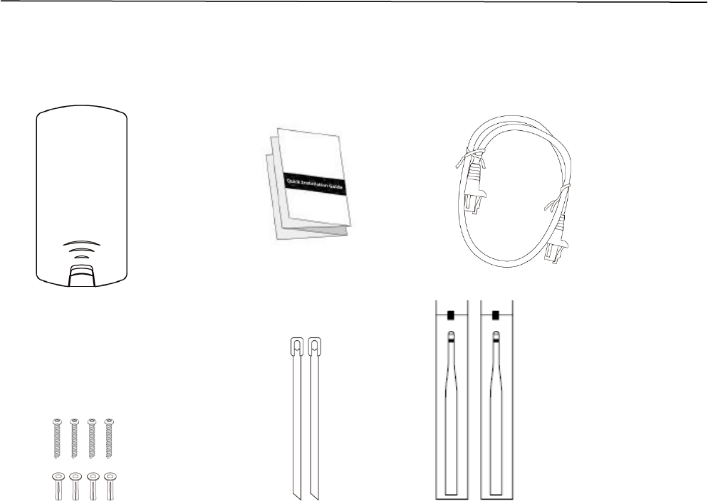
I-1. Package Contents
1. Access Point
2. Quick Installation Guide
3. Ethernet Cable
4. Wall Mount Screws Kits
5. Pole Mount Ties
6. Antenna
1
2
3
4
5
6
3
I-2. System Requirements
- Existing Ethernet cable, IEEE802.3at PoE Switch
- Computer with web browser for access point configuration
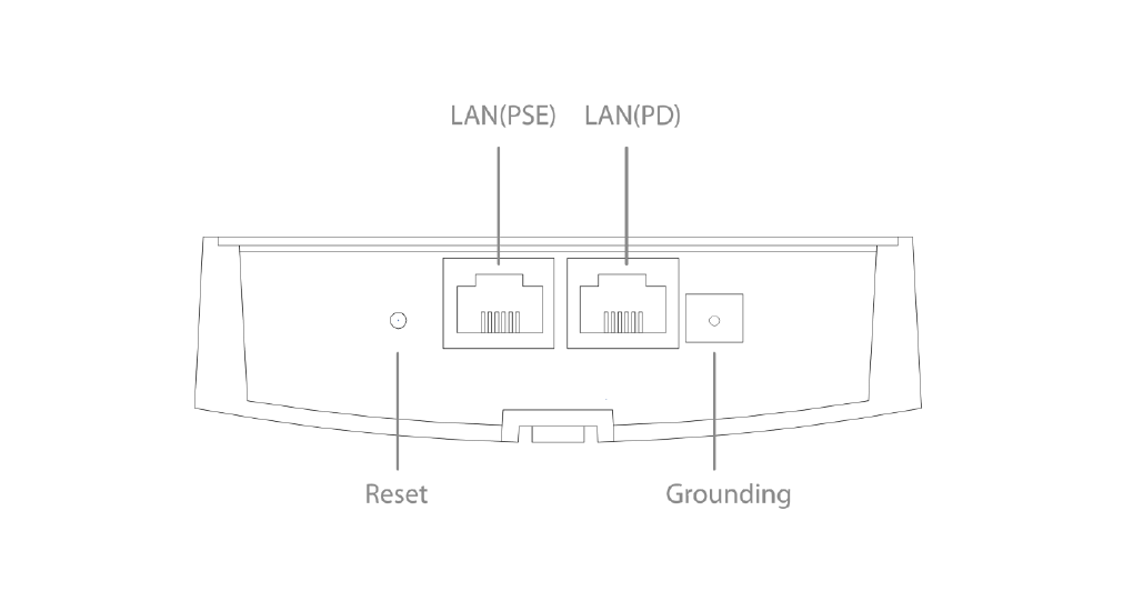
I-3. Hardware Overview
A. LAN1 port with Power over Ethernet (IEEE802.3at PoE PD-IN).
B. LAN2 port with Power over Ethernet (IEEE802.3af PoE PSE-OUT).
C. Reset Button.
D. Grounding Terminal.
B
A
C D

4
I-4. LED Status
LED Behavior
5G
ON
5G Wireless is enabled.
Off
5G Wireless is disabled.
2.4G
ON
2.4G Wireless is enabled.
Off
2.4G Wireless is disabled.
LAN2(PSE)
ON
LAN2 port is connected.
Flashing
Traffic is passing through Ethernet port.
Off
LAN2 port is unconnected.
LAN1(PD)
ON
LAN1 port is connected.
Flashing
Traffic is passing through Ethernet port.
Off
LAN1 port is unconnected.
Status
ON
Booting up process
Off
No error occur
Power
ON
The access point is on.
Flashing
Long Flashing: Firmware upgrading
Off
The access point is off.

5
I-5. Reset
If you experience problems with your access point, you can reset the device
back to its factory settings. This resets all settings back to default.
1. Press and hold the reset button on the access point for at least 10
seconds. Then release the button.
You may need to use a pencil or similar sharp object to push the
reset button.
2. Wait for the access point to restart. The access point is ready for setup
when the Status LED is OFF.
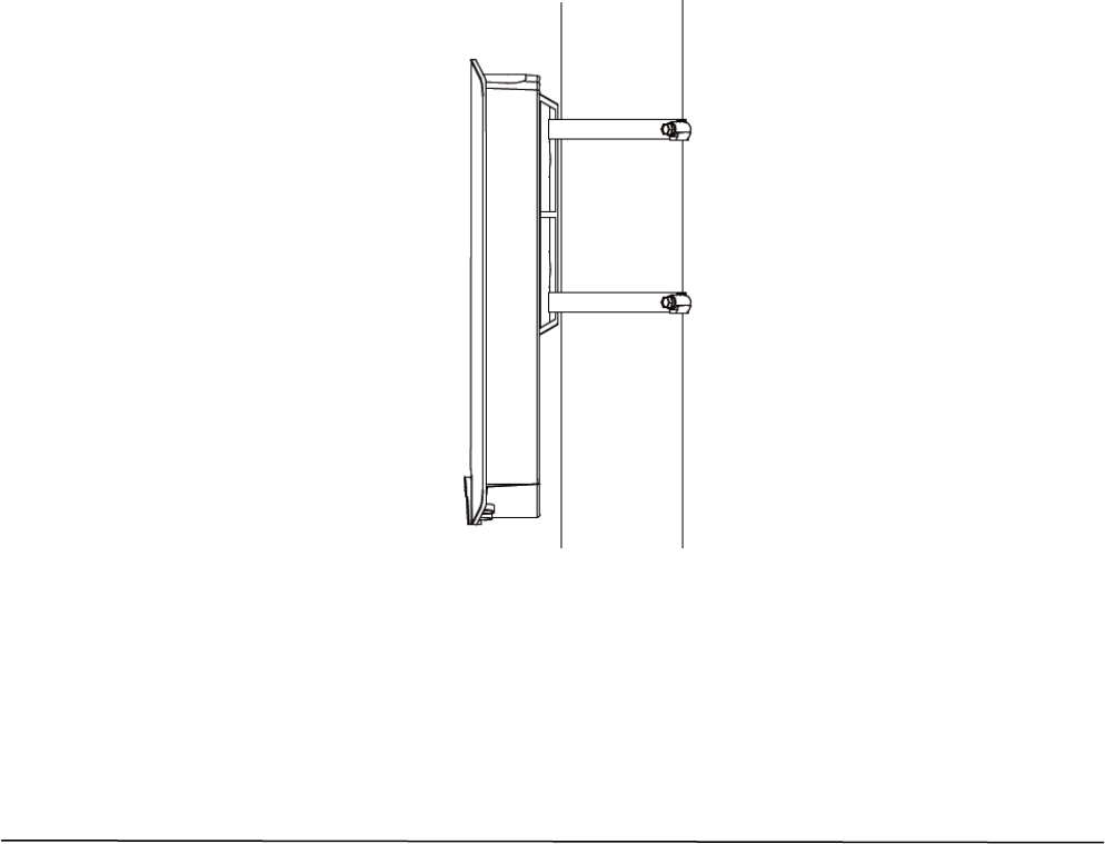
I-6. Mounting
The access point includes a mount for wall or pole which requires some
assembly.
Wall Mount
1. Attach the access point to a wall using the included screws and plugs.
6
Pole Mount
1. Fix the access point to a pole using the included stainless tie.
Attention: This product is installed in restricted access location by
professionals.
II. Quick Setup
The AC1300 Outdoor AP/CPE features a range of powerful functions:
- AC1300 high-speed wireless technology
- 16 SSIDs for management
- SNMP v1/v2c/v3
Your access point can be up and running in just a few minutes. It can function
as a standalone access point (AP mode), as part of an AP array (Managed AP
mode), or as a client bridge for WISP last-mile services (Client Bridge mode).
7
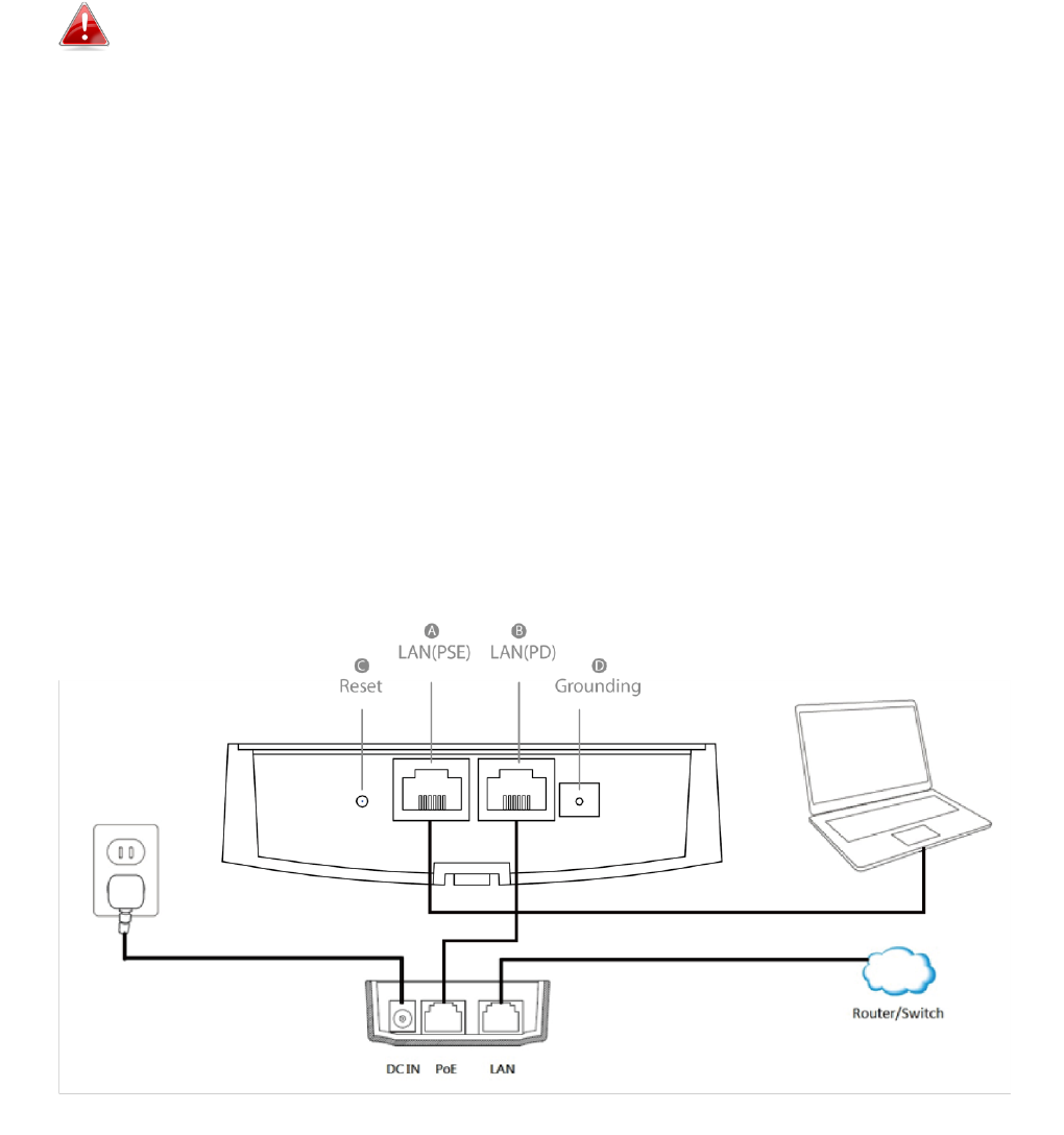
II-1. Initial Setup
Do not connect a non-PoE device to the access point’s LAN2 (PoE-
OUT) port. The LAN2 port outputs 48V and can damage a non PoE
device.
1. Connect the access point’s LAN1 (PoE-IN) port to the PoE Switch via
Ethernet cable.
2. Wait a moment for the access point to start up. The access point is ready
when the Status LED is OFF.
3. Use an Ethernet cable to connect your computer to the access point’s
LAN2 port for initial setup.
8
II-2. AP Mode
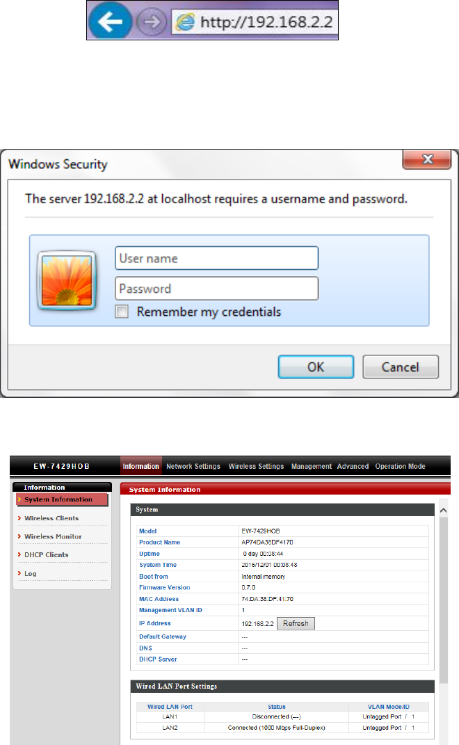
1. Enter the access point’s IP address into the URL bar of a web browser. The
default IP is 192.168.2.2. If the AP is connected to a DHCP server, ensure
you use the correct address.
2. You will be prompted for a user name and password. Enter the default
username “admin” and the default password “1234”.
3. You will arrive at the “System Information” screen shown below.
The next steps will help you to configure the following basic settings of the
access point:
9
- LAN IP Address
- 2.4G/5GHz SSID & Security
- Administrator Name & Password
- Time & Date
It is recommended you configure these settings before using the
access point.
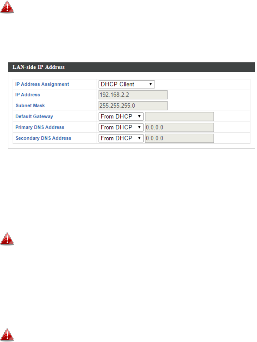
1. To change the access point’s LAN IP address, go to “Network Settings” >
“LAN-side IP Address” and you will see the screen below.
2. Enter the IP address settings you wish to use for your access point. You
can use a dynamic (DHCP) or static IP address, depending on your network
environment. Click “Apply” to save the changes and wait a few moments
for the access point to reload.
When you change your access point’s IP address, you need to use
the new IP address to access the browser based configuration
interface instead of the default IP 192.168.2.2.
3. To change the SSID of your access point’s 5GHz wireless network(s), go to
“Wireless Settings” > “5GHz 11ac” > “Basic”. Enter the new SSID for your
5GHz wireless network in the “SSID1” field and click “Apply”.
To utilize multiple 5GHz SSIDs, open the drop down menu labelled
“Enable SSID number” and select how many SSIDs you require.
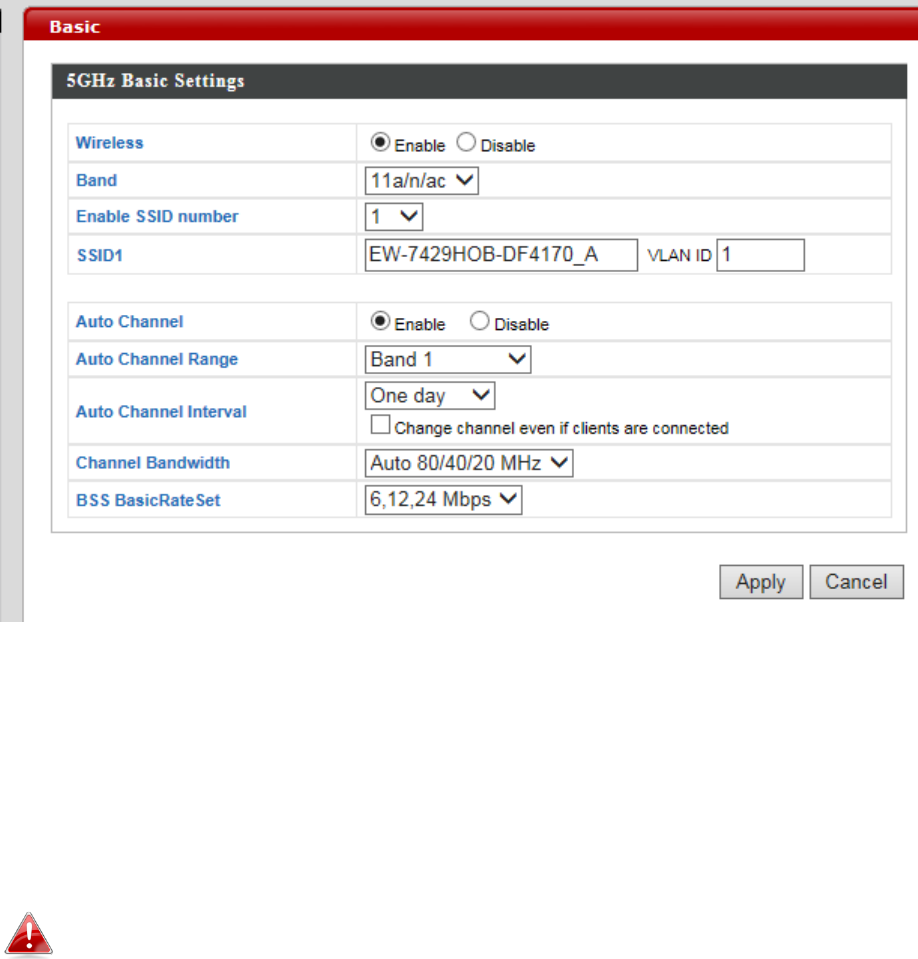
10
Then enter a new SSID in the corresponding numbered fields
below, before clicking “Apply”.
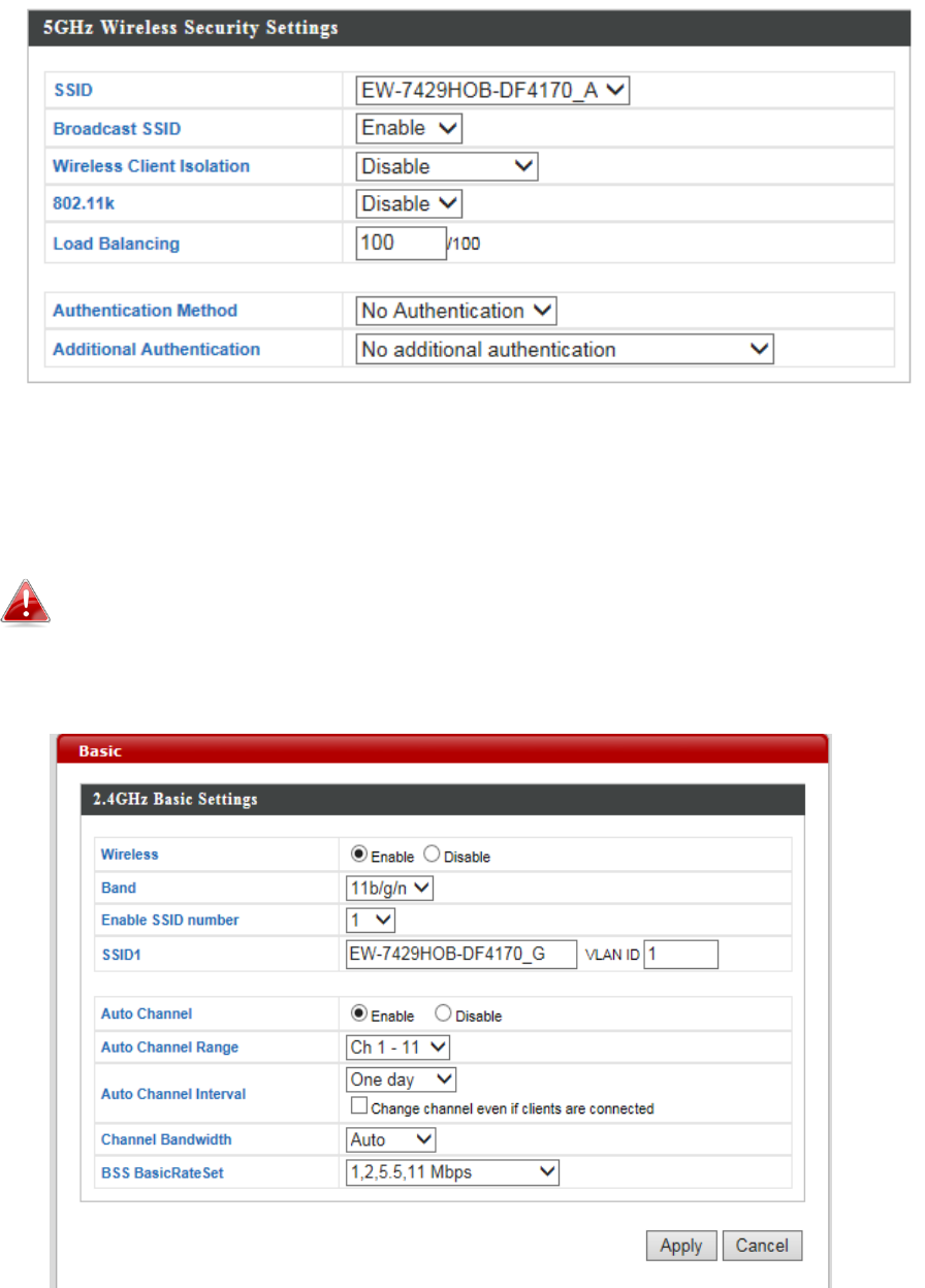
4. To configure the security of your access point’s 5GHz wireless network(s),
go to “Wireless Settings” > “5GHz 11ac 11an” > “Security”. Select an
“Authentication Method” and enter a “Pre-shared Key” or “Encryption Key”
depending on your choice, then click “Apply”.
If using multiple SSIDs, specify which SSID to configure using the
“SSID” drop down menu.
11
5. To change the SSID of your access point’s 2.4GHz wireless network(s), go to
“Wireless Settings” > “2.4GHz 11ac” > “Basic”. Enter the new SSID for your
5GHz wireless network in the “SSID1” field and click “Apply”.
To utilize multiple 2.4GHz SSIDs, open the drop down menu
labelled “Enable SSID number” and select how many SSIDs you
require. Then enter a new SSID in the corresponding numbered
fields below, before clicking “Apply”.
6. To configure the security of your access point’s 2.4GHz wireless network(s),
go to “Wireless Settings” > “2.4GHz 11ac 11an” > “Security”. Select an
“Authentication Method” and enter a “Pre-shared Key” or “Encryption Key”
depending on your choice, then click “Apply”.
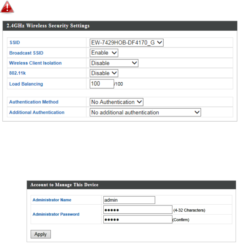
12
If using multiple SSIDs, specify which SSID to configure using the
“SSID” drop down menu.
7. To change the administrator name and password for the browser based
configuration interface, go to “Management” > “Admin”.
8. Complete the “Administrator Name” and “Administrator Password” fields
and click “Apply”.
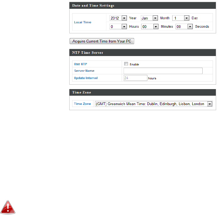
9. To set the correct time for your access point, go to “Management” >
“Date and Time Settings”.
13
10. Set the correct time and time zone for your access point using the
drop down menus. The access point also supports NTP (Network Time
Protocol) so alternatively you can enter the host name or IP address of a
time server. Click “Apply” when you are finished.
You can use the “Acquire Current Time from your PC” button if
you wish to set the access point to the same time as your PC.
11. The basic settings of your access point are now configured.

14
III. Hardware Specification
Hardware Specification
MCU/RF
Qualcomm Atheros IPQ 4018 Quad-Core 710MHz
Memory
DDR3 256MB
Flash
SPI NOR 32MB
Physical
Interface
- LAN1: Gigabit Ethernet with IEEE802.3at PoE PD-IN support
- LAN2: Gigabit Ethernet with IEEE802.3af PoE PSE-OUT support
- Reset Button x 1
- Grounding Terminal x 1
- RP-SMA Connector x 2
Power
Requirement
IEEE802.3at Power over Ethernet
Antenna
External Dual Band Dipole Antenna x 2 (2.4G: 3dBi, 5G: 4dBi)
ENVIRONMENT & PHYSICAL
Temperature Range
Operation : -40 to 60℃ (-40℉ to 140℉)
Storage : -40 to 70℃ (-40℉ to 158℉)
Humidity
90% or less – Operating, 90% or less - Storage
Certifications
FCC, CE, IEC60950-1, IEC60950-22
Dimensions (TBD)
242.27(L) x 120.93(W) x 48.78(D)mm
Weight
632g (AP: 594g, Antenna: 38g)
International
Protection Rated
IP5X, IPX6

15
Any changes or modifications not expressly approved by the party responsible for compliance could void
the user's authority to operate this equipment.
This device complies with Part 15 of the FCC Rules. Operation is subject to the following two conditions:
(1) this device may not cause harmful interference, and (2) this device must accept any interference
received, including interference that may cause undesired operation.
This equipment has been tested and found to comply with the limits for a Class B digital device,
pursuant to Part 15 of FCC Rules. These limits are designed to provide reasonable protection against
harmful interference in a residential installation. This equipment generates, uses, and can radiate radio
frequency energy and, if not installed and used in accordance with the instructions, may cause harmful
interference to radio communications. However, there is no guarantee that interference will not occur
in a particular installation. If this equipment does cause harmful interference to radio or television
reception, which can be determined by turning the equipment off and on, the user is encouraged to try
to correct the interference by one or more of the following measures:
1. Reorient or relocate the receiving antenna.
2. Increase the separation between the equipment and receiver.
3. Connect the equipment into an outlet on a circuit different from that to which the receiver is
connected.
4. Consult the dealer or an experienced radio technician for help.
FCC Radiation Exposure Statement:
This equipment complies with FCC RF radiation exposure limits set forth for an uncontrolled
environment. This equipment should be installed and operated with a minimum distance of 20
centimeters between the radiator and your body or nearby persons.