Ehong Technology MC20 Bluetooth Module User Manual
ShangHai Ehong Technology Co.,Ltd. Bluetooth Module
User Manual

Shanghai Ehong Technologies Inc
EH-MC20
Bluetooth® technology low energy
module
•
Bluetooth® radio
- Fully embedded Bluetooth® v4.2 single mode
- TX power +4 dbm,-92dbm RX sensitivity@1M
- 128-bit encryption security
- Range up to 50m
- Integrated on board PCB antenna
- Multipoint capability(master and slave at the
same time)
•
Support profiles
- BLE (Master and slave)
- The generic attribute profile (GATT)
- Health care, Sports and fitness, Proximity
sensing profiles
- Alerts and timer profiles
•
User interface
- Send AT command over UART
- Firmware upgrade over the air (OTA)
- Transmit data: 300kbps transmission speed
(UART)
- I2C interface(Master )
- USB
- PWM(6 channel)
•
General
I/O
-
10 general purpose I/Os
-
7 analogue I/O
(14bit ADC)
•
The price is cheap
•
Single voltage supply: 3.3V typical
•
Small form factor: 18.10 x 12.05x 2.2mm
•
Operating temperature range: -40 °C to 85 °C
Version 1.0
Oct 23, 2016

Bluetooth Low Energy Module
Shanghai Ehong Technologies Co., Ltd
1. Contents
1. Description ................................................................................................................................................................ 4
2. Applications .............................................................................................................................................................. 4
3. EH-MC20 Product numbering ............................................................................................................................. 4
4. Electrical Characteristics ..................................................................................................................................... 5
4.1. Recommended Operation Conditions .......................................................................................................... 5
4.2. Absolute Maximum Rating .............................................................................................................................. 5
4.3. Input/Output Terminal Characteristics .......................................................................................................... 5
4.4. Power Consumption ......................................................................................................................................... 6
5. Pinout and Terminal Description ........................................................................................................................ 7
5.1. Pin Configuration ............................................................................................................................................... 7
6. Physical Interfaces.................................................................................................................................................. 9
6.1. Power Supply ..................................................................................................................................................... 9
6.2. PIO ........................................................................................................................................................................ 9
6.3. AIO ...................................................................................................................................................................... 10
6.4. PWM ................................................................................................................................................................... 10
6.5. UART.................................................................................................................................................................. 10
6.6. USB interface ................................................................................................................................................... 11
6.7. I2C Master ........................................................................................................................................................ 11
6.8. SPI Debug ......................................................................................................................................................... 11
7. Reference Design .................................................................................................................................................. 12
8. Layout and Soldering Considerations ........................................................................................................... 13
8.1. Soldering Recommendations ....................................................................................................................... 13
8.2. Layout Guidelines............................................................................................................................................ 13
9. Mechanical and PCB Footprint Characteristics.......................................................................................... 14
10. Packaging ............................................................................................................................................................ 15

Bluetooth Low Energy Module
Shanghai Ehong Technologies Co., Ltd
11. Reflow Profile ..................................................................................................................................................... 16
12. Contact Information ......................................................................................................................................... 17
2. Table of Tables
TABLE 1: RECOMMENDED OPERATION CONDITIONS ........................................................................................................ 5
TABLE 2:ABSOLUTE MAXIMUM RATING ........................................................................................................................... 5
TABLE 3: DIGITAL I/O CHARACTERISTICS .......................................................................................................................... 5
TABLE 4: AIO CHARACTERISTICS ....................................................................................................................................... 5
TABLE 6: CURRENT CONSUMPTION .................................................................................................................................... 6
TABLE 7:PIN TERMINAL DESCRIPTION ............................................................................................................................ 9
TABLE 8: POSSIBLE UART SETTINGS .............................................................................................................................. 10
3. Table of Figures
FIGURE 1: PINOUT OF EH-MC20 .................................................................................................................................... 7
FIGURE 2: POWER SUPPLY PCB DESIGN....................................................................................................................... 9
FIGURE 3: CONNECTION TO HOST DEVICE ................................................................................................................... 10
FIGURE 4: REFERENCE DESIGN ..................................................................................................................................... 12
FIGURE 5: CLEARANCE AREA OF ANTENNA ...................................................................................................................... 14
FIGURE 6 :PHYSICAL DIMENSIONS AND RECOMMENDED FOOTPRINT (UNIT: MM, DEVIATION:0.02MM) ................ 15
FIGURE 7: EH-MC20 PACKAGING(PALLET) .............................................................................................................. 16
FIGURE 8: RECOMMENDED REFLOW PROFILE................................................................................................................ 16

Bluetooth Low Energy Module
Shanghai Ehong Technologies Co., Ltd
1. Description
EH-MC20 Bluetooth® low energy single mode module is a single mode device targeted for
low power sensors and accessories.
The module offers all Bluetooth® low energy features: radio, stack, profiles and application
space for customer applications, so no external processor is needed. The module also provides
flexible hardware interfaces to connect s e n sors , s imp l e u s e r i n t e r f a c es o r even
displays directly to the module.
The module internal integration 32bit MCU and 128KB flash, external interface is rich
(AIO,PWM,UART,USB), and the price is cheap.
After buying Bluetooth® module, we provide free technical support APP of iOS system or APP
Android system.
2. Applications
Sports and fitness
Healthcare
Home entertainment
Office and mobile accessories
Automotive
Commercial
Watches
Human interface devices
3. EH-MC20 Product numbering
EH-MC20
A. EH ------------- Company Name(EHong)
B. MC20 ------------ Module Name
Bluetooth Low Energy Module
Shanghai Ehong Technologies Co., Ltd
4. Electrical Characteristics
4.1. Recommended Operation Conditions
Table 1: Recommended Operation Conditions
Operating Condition Min Typical Max Unit
Operating Temperature Range -40 -- +85 °C
Battery (VDD_BAT) operation 1.9 -- +3.6 V
I/O Supply Voltage (VDD_PIO) 1.9 -- +3.6 V
AIO input 0 - +1.9 V
Frequency range 2402 2480 MHz
Table 2:Absolute Maximum Rating
4.2. Absolute Maximum Rating
4.3. Input/Output Terminal Characteristics
Table 3: Digital I/O Characteristics
Input Voltage Levels Min Typical Max Unit
VIL input logic level low VSS - 0.3VDD V
VIH input logic level high 0.7 x VDD - VDD V
Output Voltage Levels Min Typical Max Unit
VOL output logic level low, lOL = 4.0mA VSS - 0.3VDD V
VOH output logic level high, lOH = -4.0mA VDD-0.3 - VDD V
Table 4: AIO Characteristics
Input Voltage Levels Min Typical Max Unit
AIO 0 - 3.3 V
Rating Min Max Unit
Storage Temperature -65 +150 °C
Battery (VBAT) operation* -0.3 3.9 V
I/O supply voltage -0.3 +VDD+0
.3 V
Bluetooth Low Energy Module
Shanghai Ehong Technologies Co., Ltd
4.4. Power Consumption
The current consumption are measured at the VBAT
Table 5: Current Consumption
Item Sym Min Typ Max Unit condition
TX ITx 15 mA
Continuous Tx
Transmission 0db
output power
RX IRX 12 mA
Continuous Tx
reception
Suspend Current
Isusp - 10 50 uA IO wakeup
Isusp - 12 52 uA Timer wakeup
Deep sleep Current Ideep - 2 5 uA
Bluetooth Low Energy Module
Shanghai Ehong Technologies Co., Ltd
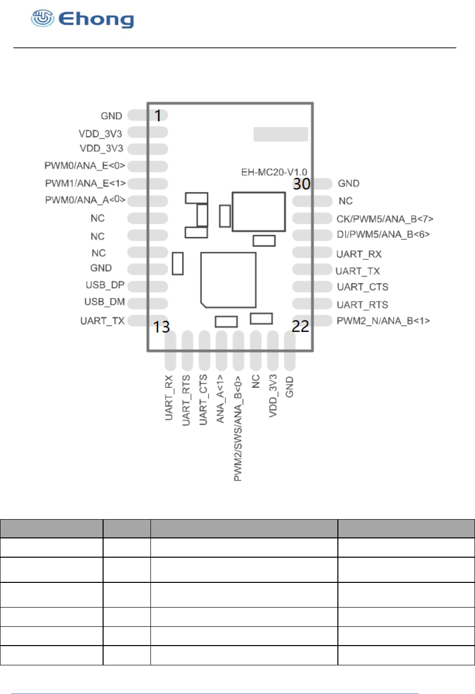
5. Pinout and Terminal Description
5.1. Pin Configuration
Figure 1: Pinout of EH-MC20
Symbol Pin PAD Type Description
GND 1 Ground Ground
VDD_3V3 2 Power supply Button cell battery or DC
1.8V to 3.6V
VDD_3V3 3 Power supply Button cell battery or DC
1.8V to 3.6V
PWM0/ANA_E(0) 4 Digital I/O PWM0/GPIO/ANA_E0
PWM1/ANA_E(1) 5 Digital I/O PWM1/GPIO/ANA_E1
PWM0/ANA_A(0) 6 Digital I/O PWM0/GPIO/ANA_A0

Bluetooth Low Energy Module
Shanghai Ehong Technologies Co., Ltd
NC 7 NC NC
NC 8 NC NC
NC 9 NC NC
GND 10 Ground Ground
USB_DP 11 Digital I/O USB data
positive/GPIO/ANA_E3
USB_DM 12 Digital I/O USB data
Minus/GPIO/ANA_E3
UART_TX
13
Digital I/O
UART_TX/PWM2/GPIO/A
NA_C2
Optional 32KHz crystal
output
UART_RX
14
Digital I/O
UART_TX/PWM3/GPIO/A
NA_C3
Optional 32KHz crystal
input
UART_RTS 15 Digital I/O UART_RTS/PWM3/GPIO/
ANA_C4
UART_CTS 16 Digital I/O UART_RTS/PWM4/GPIO/
ANA_C4
ANA_A(1) 17 Digital I/O ANA_A1
PWM2/SW/AN
A_B(0)
18
Digital I/O PWM2/single wire
slave/GPIO/ANA_B(0)
NC 19 NC NC
VDD_3V3 20 Power Supply Button cell battery or DC
1.8V to 3.6V
GND 21 Ground Ground
PWM2_N/ANA
_B(1)
22
Digital I/O PWM2
inverting/GPIO/ANA_B1
UART_RTS 23 Digital I/O UART_RTS/PWM3/GPIO/
ANA_C4
UART_CTS 24 Digital I/O UART_RTS/PWM4/GPIO/
ANA_C4
UART_TX
25
Digital I/O
UART_TX/PWM2/GPIO/A
NA_C2
Optional 32KHz crystal
output
UART_RX
26
Digital I/O
UART_TX/PWM3/GPIO/A
NA_C3
Optional 32KHz crystal
input
DI/PWM5/ANA
_B(6)
27 Digital I/O I2C_SDA/PWM5/GPIO/AN
A_B6
Bluetooth Low Energy Module
Shanghai Ehong Technologies Co., Ltd
CK/PWM5/ANA_B(
7)
28
Digital I/O I2C_CLK/PWM5
inverting/GPIO/ANA_B7
NC
29
NC NC
GND
30
Ground Ground
Table 6:PIN Terminal Description
Note:
A. UART_TX > PIN13 and PIN25 are the same PIN and feature.
B. UART_RX>PIN14 and PIN26 are the same PIN and feature.
C. UART_RTS>PIN15 and PIN23 are the same PIN and feature.
D. UART_CTS>PIN16 and PIN24 are the same PIN and feature
6. Physical Interfaces
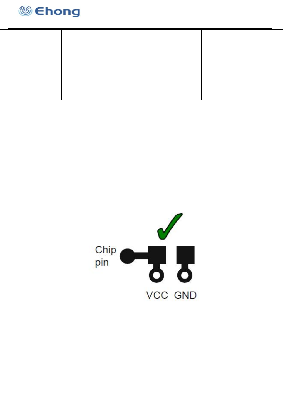
6.1. Power Supply
- The module power supply 3v coin cell batteries or DC 3.3v
- Power supply pin connection capacitor to chip and pin as far as possible close
- Capacitor decouples power to the chip
- Capacitor prevents noise coupling back to power plane.
-
Figure 2: Power Supply PCB Design
6.2. PIO
14 PIOs are provided . They are powered from VDD.PIO lines are software-configurable
as weak pull-up, weak pull-down, strong pull-up or strong pull-down.
Note:
At reset all PIO lines are inputs with weak pull-downs.
Bluetooth Low Energy Module
Shanghai Ehong Technologies Co., Ltd
6.3. AIO
14 AIOs are provided. They can be connected to internal 14 bits ADC. Their functions
depend on software.
6.4. PWM
6 PIOs can be driven by internal PWM module. The PWM module also works while the
module is sleep. So it can be used as a LED flasher. These functions are controlled by
special firmware.
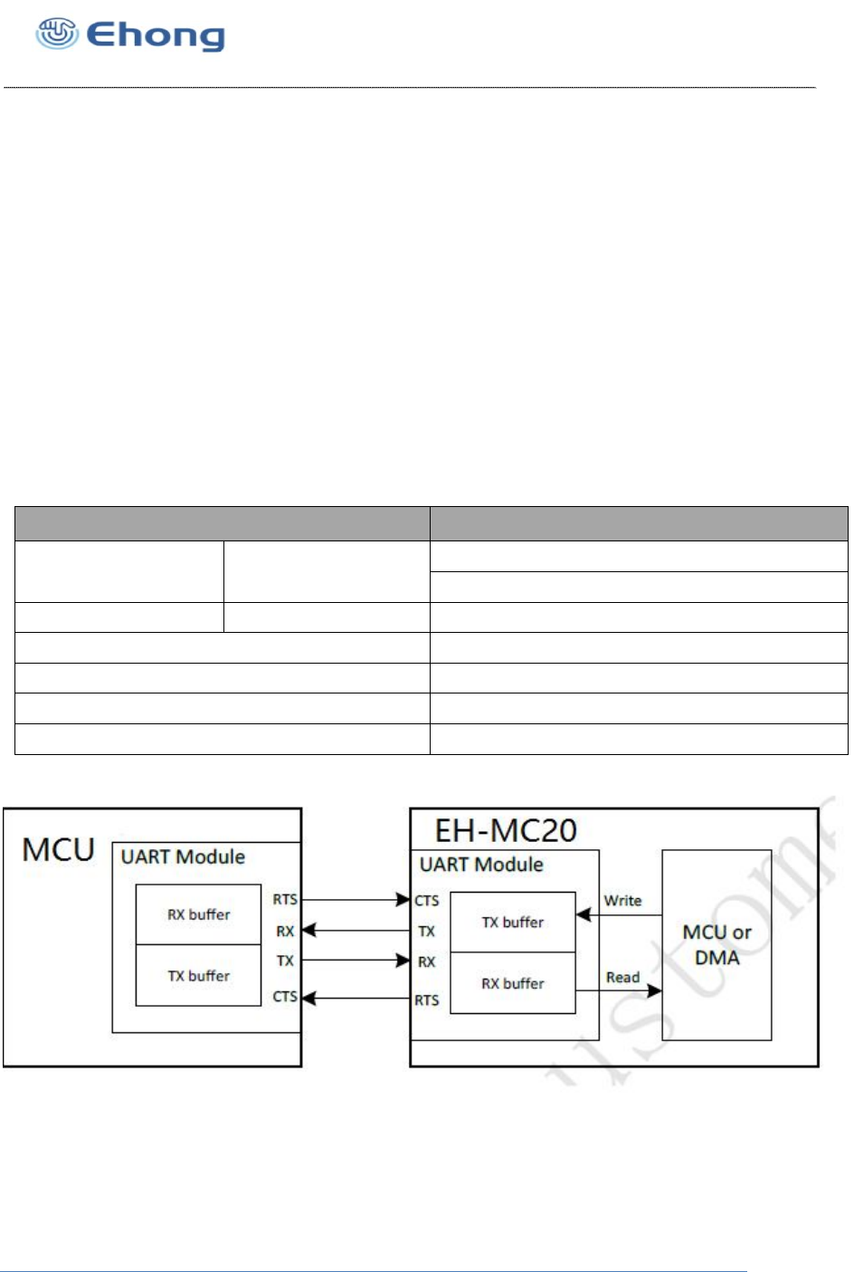
6.5. UART
This is a standard UART interface for communicating with other serial devices and
Support UART hardware flow control.The UART interface provides a simple mechanism
for communicating with other serial devices using the RS232 protocol.
Table 7: Possible UART Settings
Figure 3: Connection To Host device
Parameter Possible Values
Baud Rate Minimum 1200 baud (≤2%Error)
9600 baud (≤1%Error)
Maximum 2M baud (≤1%Error)
Flow Control RTS/CTS
Parity None, Odd or Even
Number of Stop Bits 1 or 2
Bits per Byte 8

Bluetooth Low Energy Module
Shanghai Ehong Technologies Co., Ltd
6.6. USB interface
USB interface compatible with USB 2.0 full speed mode, support 9 endpoints, support
ISP (In-system programming) Via USB port.
6.7. I2C Master
The module can act as an I2C master when configured by software. The module PIN27
and PIN28 two PIOs can be configured as I2C_SCL and I2C_SDA.
.
6.8. SPI Debug
The module support single wire interface SWM(single wire master) and SWS(single
wire slave) represent the master and slave device of the single wire communication
system developed by Ehong. The maximum data rate can be up to 2Mbps.
Bluetooth Low Energy Module
Shanghai Ehong Technologies Co., Ltd
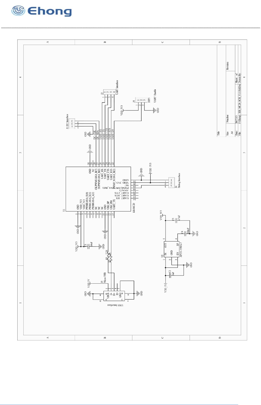
7. Reference Design
Figure 4: Reference Design
Note:
Please keep pulling up the WAKE pin during sending data to the module.

Bluetooth Low Energy Module
Shanghai Ehong Technologies Co., Ltd
8. Layout and Soldering Considerations
8.1. Soldering Recommendations
EH-MC20 is compatible with industrial standard reflow profile for Pb-free solders. The
reflow profile used is dependent on the thermal mass of the entire populated PCB, heat
transfer efficiency of the oven and particular type of solder paste used. Consult the
datasheet of particular solder paste for profile configurations.
Comply will give following recommendations for soldering the module to ensure reliable
solder joint and operation of the module after soldering. Since the profile used is
process and layout dependent, the optimum profile should be studied case by case.
Thus following recommendation should be taken as a starting point guide.
Refer to technical documentations of particular solder paste for profile
configurations
Avoid using more than one flow.
Reliability of the solder joint and self-alignment of the component are dependent on
the solder volume. Minimum of 150um stencil thickness is recommended.
Aperture size of the stencil should be 1:1 with the pad size.
A low residue, “no clean” solder paste should be used due to low mounted height of
the component.
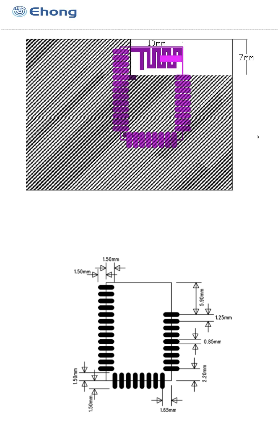
8.2. Layout Guidelines
For optimal performance of the antenna place the module at the corner of the PCB as shown in the figure
3. Do not place any metal (traces, components, battery etc.) within the clearance area of the antenna.
Connect all the GND pins directly to a solid GND plane. Place the GND vias as close to the GND pins as
possible. Use good layout practices to avoid any excessive noise coupling to signal lines or supply
voltage lines. Avoid placing plastic or any other dielectric material closer than 6 mm from the antenna.
Any dielectric closer than 6 mm from the antenna will detune the antenna to lower frequencies.
Bluetooth Low Energy Module
Shanghai Ehong Technologies Co., Ltd
Figure 5: Clearance area of antenna
9. Mechanical and PCB Footprint Characteristics
Bluetooth Low Energy Module
Shanghai Ehong Technologies Co., Ltd
Figure 6 :Physical Dimensions and Recommended Footprint (Unit: mm, Deviation:0.02mm)
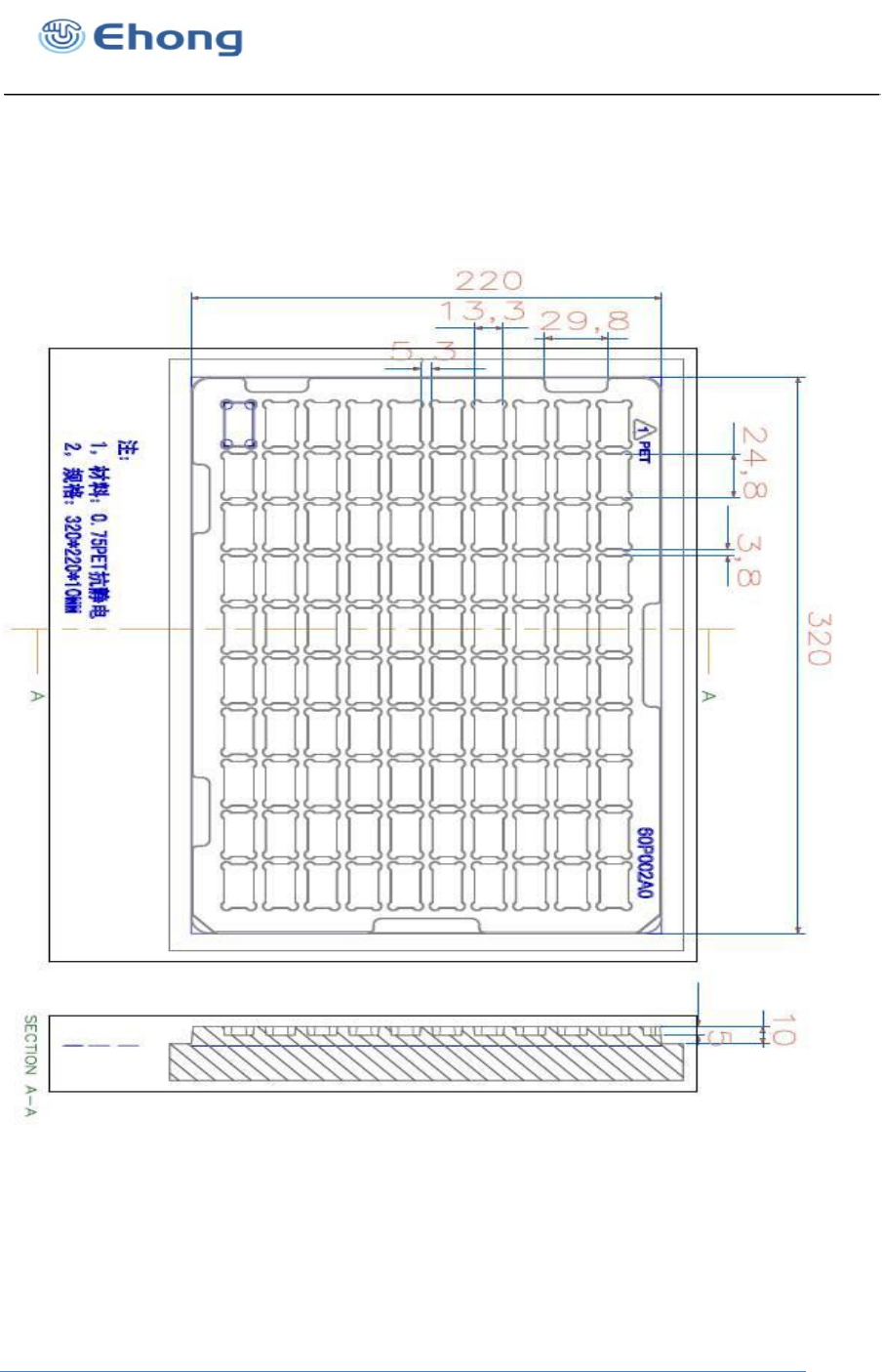
10. Packaging
Bluetooth Low Energy Module
Shanghai Ehong Technologies Co., Ltd
Figure 7: EH-MC20 Packaging(Pallet)
packaging for the pallet,one packaging quantity is 100 PCS。
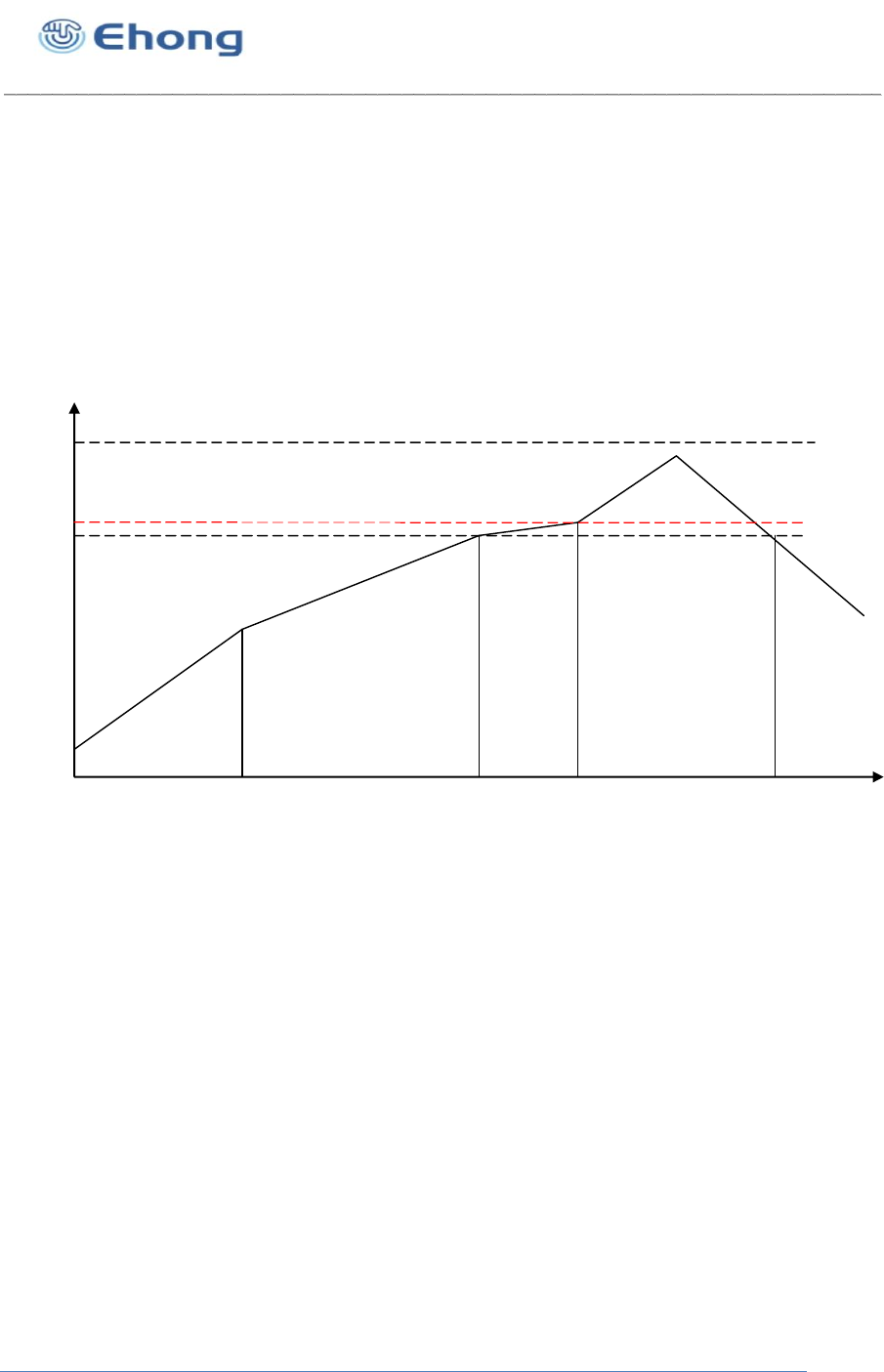
11. Reflow Profile
The soldering profile depends on various parameters necessitating a set up for each application.
The data here is given only for guidance on solder reflow.
210
217
℃
250
A B C D
1 2
0
25
3 4 5 6 min
E
Figure 8: Recommended Reflow Profile
Pre-heat zone (A) — This zone raises the temperature at a controlled rate, typically 0.5 – 2
C/s. The purpose of this zone is to preheat the PCB board and components to 120 ~ 150 C.
This stage is required to distribute the heat uniformly to the PCB board and completely remove
solvent to reduce the heat shock to components.
Equilibrium Zone 1 (B) — In this stage the flux becomes soft and uniformly encapsulates
solder particles and spread over PCB board, preventing them from being re-oxidized. Also with
elevation of temperature and liquefaction of flux, each activator and rosin get activated and start
eliminating oxide film formed on the surface of each solder particle and PCB board. The
temperature is recommended to be 150 to 210 for 60 to 120 second for this zone.
Equilibrium Zone 2 (c) (optional) — In order to resolve the upright component issue, it is
recommended to keep the temperature in 210 – 217 for about 20 to 30 second.
Reflow Zone (D) — The profile in the figure is designed for Sn/Ag3.0/Cu0.5. It can be a
reference for other lead-free solder. The peak temperature should be high enough to achieve
good wetting but not so high as to cause component discoloration or damage. Excessive
soldering time can lead to intermetallic growth which can result in a brittle joint. The

Bluetooth Low Energy Module
Shanghai Ehong Technologies Co., Ltd
recommended peak temperature (Tp) is 230 ~ 250 C. The soldering time should be 30 to 90
second when the temperature is above 217 C.
Cooling Zone (E) — The cooling ate should be fast, to keep the solder grains small which will
give a longerlasting joint. Typical cooling rate should be 4 C.
12. Contact Information
Sales: sales@ehlink.com.cn
Technical support: support@ehlink.com.cn
Phone: +86 21 64769993
Fax: +86 21 64765833
Street address: Rom1505, Blk 1st ,No.833 South Hong mei Rd ,Ming hang district shanghai
FCC/IC Statements
Integrator is reminded to assure that these installation instructions
will not be made available to the end-user of the final host device.
The final host device, into which this RF Module isintegrated" hasto be labelled
with an auxilliary lable stating the FCC IDofthe RF Module,such as
"This device complies with part 15 of the FCC rules. Operation is subject to the following two
conditions:
(1)this devicemay not cause harmful interference, and
(2)this devicemust accept any interference received, including
interference thatmay cause undesired operation."
approved by the party responsible for compliance could
"Contains FCC ID:2ACCRMC20
the Integrator will be responsible to satisfy SAR/ RF Exposure requirements,
when the module integrated into the host device.
The final host device, into which this RF Module isintegrated" hasto be labelled
with an auxilliary lable stating the IC ofthe RF Module,such as
"Contains transmitter module IC:20625-EHMC20
void the user’s authority to operate the equipment."
"Changes or modifications to this unit not expressly
This device complies with Industry Canada licence-exempt RSS standard(s). Operation is
subject to the following two conditions:
(1) this device may not cause interference, and
(2) this device must accept any interference, including interference that may cause
undesired operation of the device.
Le présent appareil est conforme aux CNR d'Industrie Canada applicables aux appareils
radio exempts de licence. L'exploitation est autorisée aux deux conditions suivantes :
(1) l'appareil ne doit pas produire de brouillage, et
(2) l'utilisateur de l'appareil doit accepter tout brouillage radioélectrique subi, même si le
brouillage est susceptible d'en compromettre le fonctionnement.
(OEM) Integrator has to assure compliance of the entire end-product incl. the integrated RF Module.
For 15 B (§15.107 and if applicable §15.109) compliance, the host manufacturer is required to
show compliance with 15 while the module is installed and operating.
Furthermore the module should be transmitting and the evaluation should confirm that the module's
intentional emissions (15C) are compliant (fundamental / out-of-band). Finally the integrator has
to apply the appropriate equipment authorization (e.g. Verification) for the new host device per
definition in §15.101.
NOTE: This equipment has been tested and found to comply with the limits for a
Class B digital device, pursuant to part 15 of the FCC Rules. These limits are
designed to provide reasonable protection against harmful interference in a
residential installation. This equipment generates uses and can radiate radio
frequency energy and, if not installed and used in accordance with the instructions,
may cause harmful interference to radio communications. However, there is no
guarantee that interference will not occur in a particular installation. If this
equipment does cause harmful interference to radio or television reception, which
can be determined by turning the equipment off and on, the user is encouraged to
try to correct the interference by one or more of the following measures:
- Reorient or relocate the receiving antenna.
- Increase the separation between the equipment and receiver.
-Connect the equipment into an outlet on a circuit different from that to which the
receiver is connected.
-Consult the dealer or an experienced radio/TV technician for help
This transmitter/module must not be collocated or operating in conjunction with
any other antenna or transmitter.
Module statement
The single-modular transmitter is a self-contained, physically delineated, component
for which compliance can be demonstrated independent of the host operating
conditions, and which complies with all eight requirements of § 15.212(a)(1) as
summarized below.
1) The radio elements have the radio frequency circuitry shielded.
2) The module has buffered modulation/data inputs to ensure that the device will
comply with Part 15 requirements with any type of input signal.
3) The module contains power supply regulation on the module.
4) The module contains a permanently attached antenna.
5) The module demonstrates compliance in a stand-alone configuration.
6) The module is labeled with its permanently affixed FCC ID label
7) The module complies with all specific rules applicable to the transmitter, including
all the conditions provided in the integration instructions by the grantee.
8) The module complies with RF exposure requirements.