Election Systems and Software ESSM100A Optical Scan Voting Machine with GSM User Manual ES M100 OP 5 2ed
Election Systems & Software Optical Scan Voting Machine with GSM ES M100 OP 5 2ed
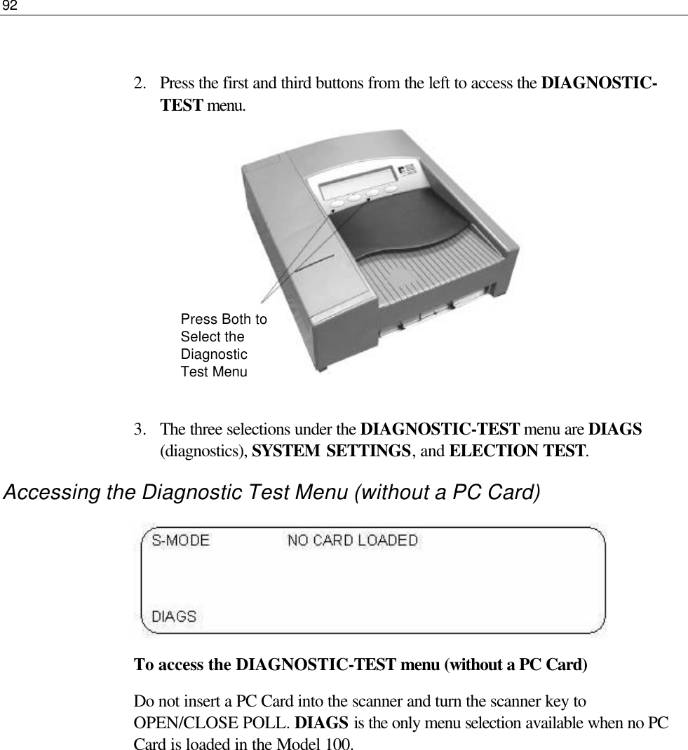
Contents
- 1. GR48 User Guide
- 2. M100 User Manual
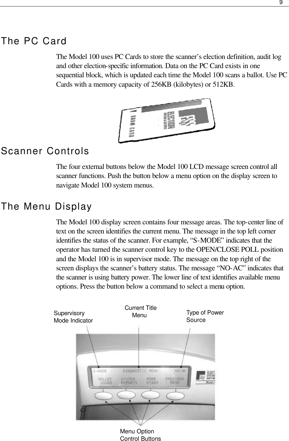
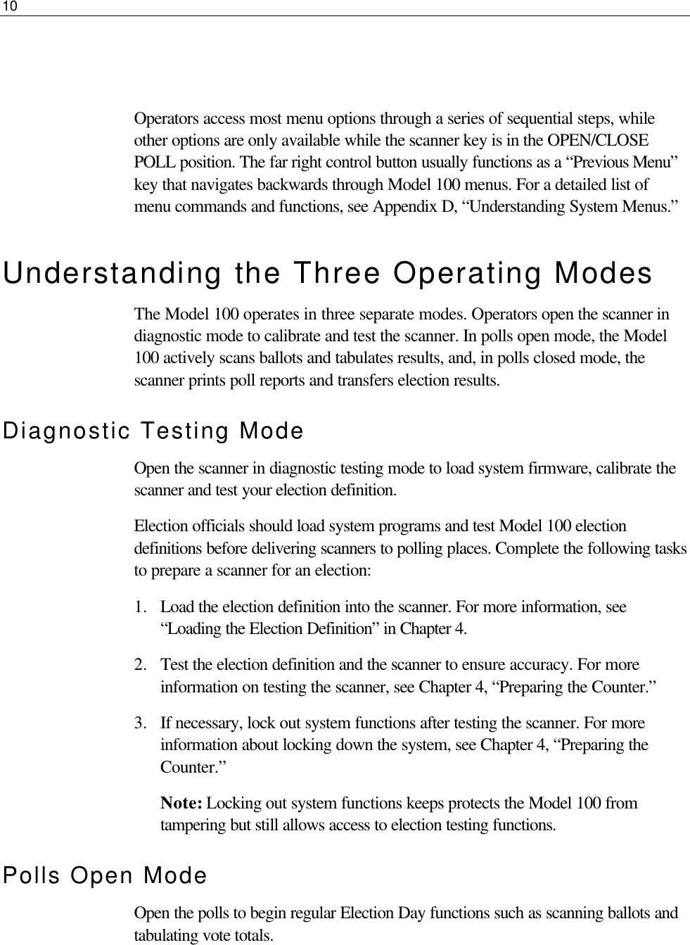
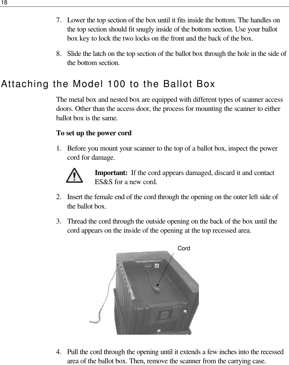
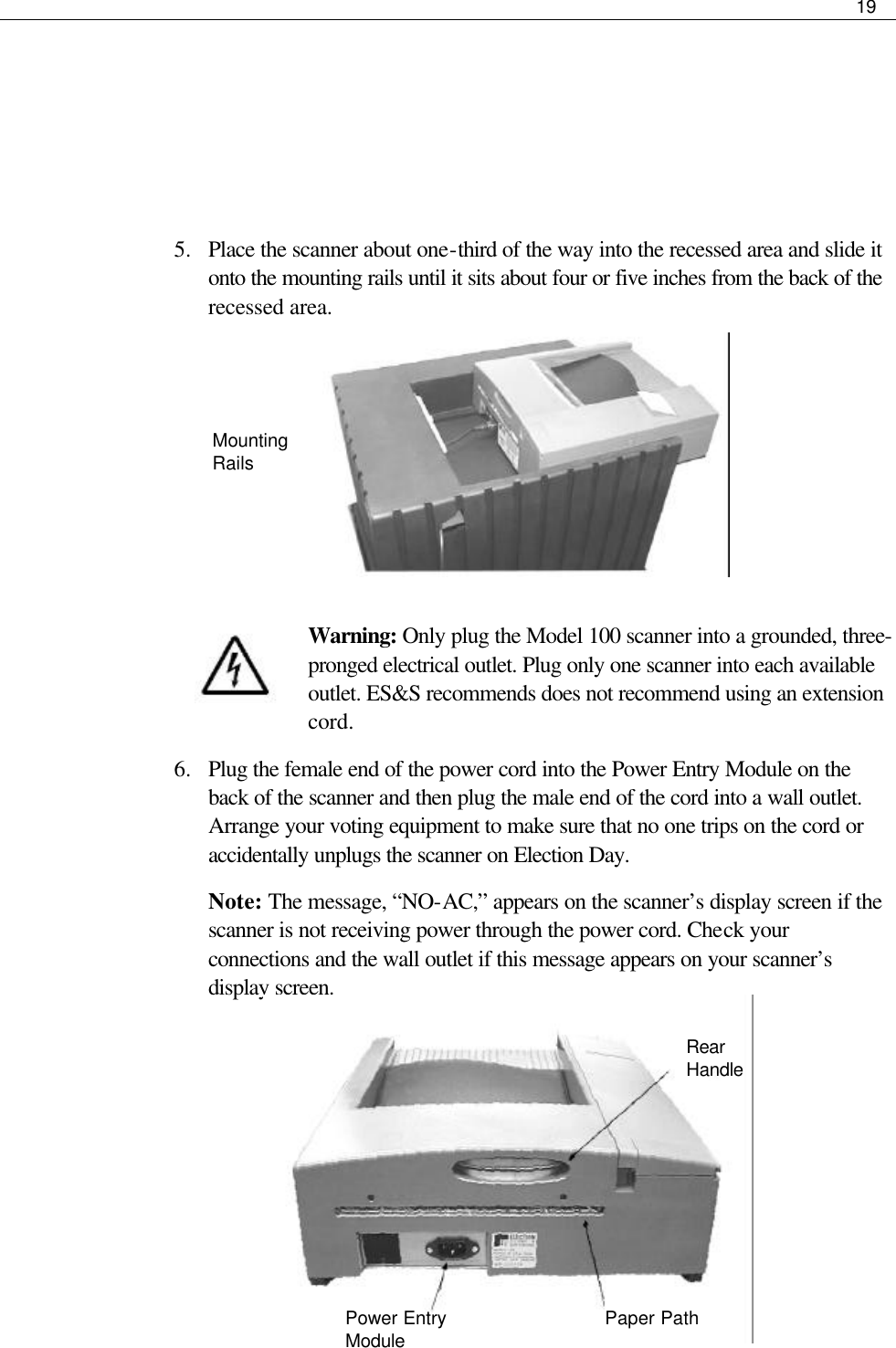
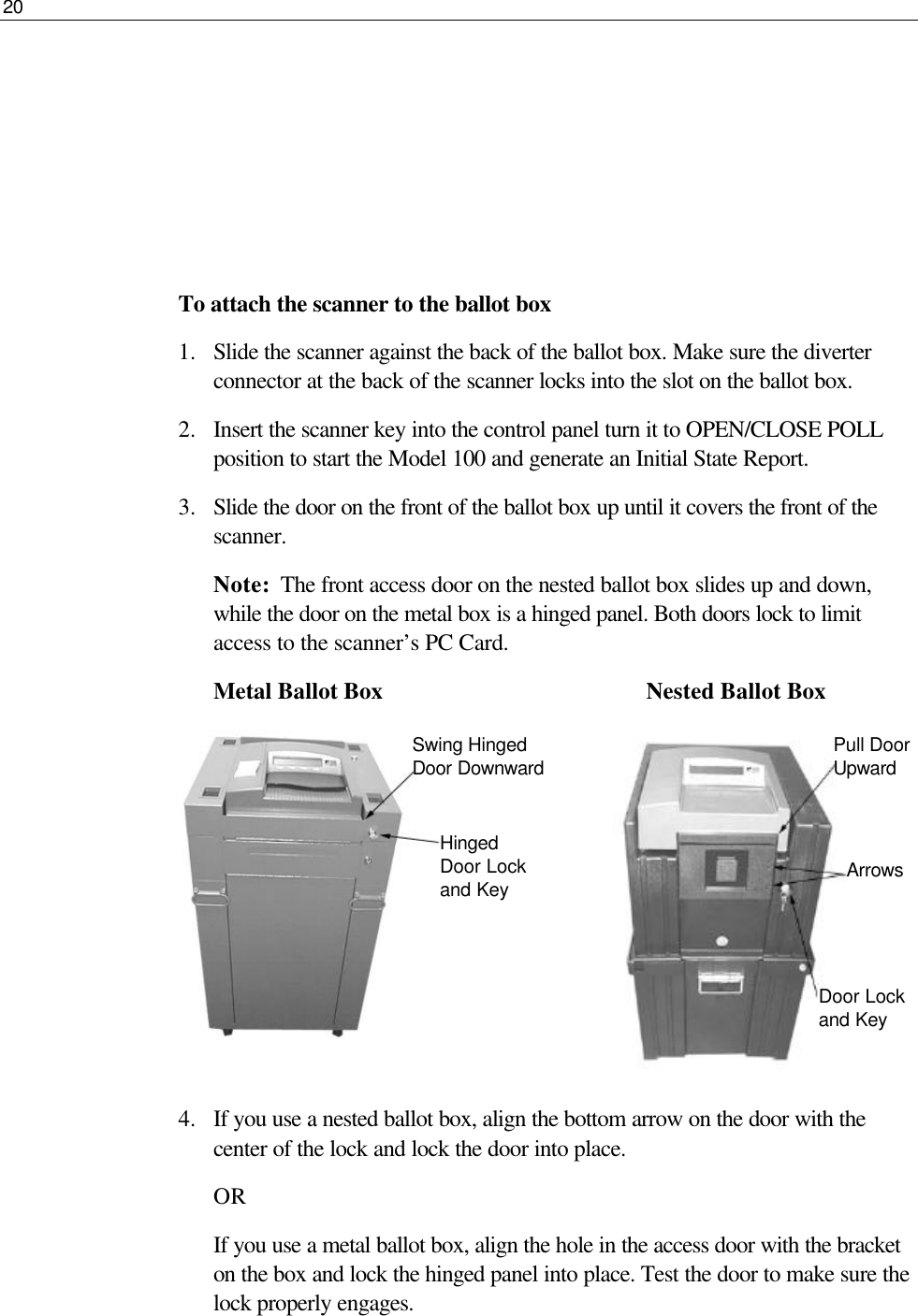
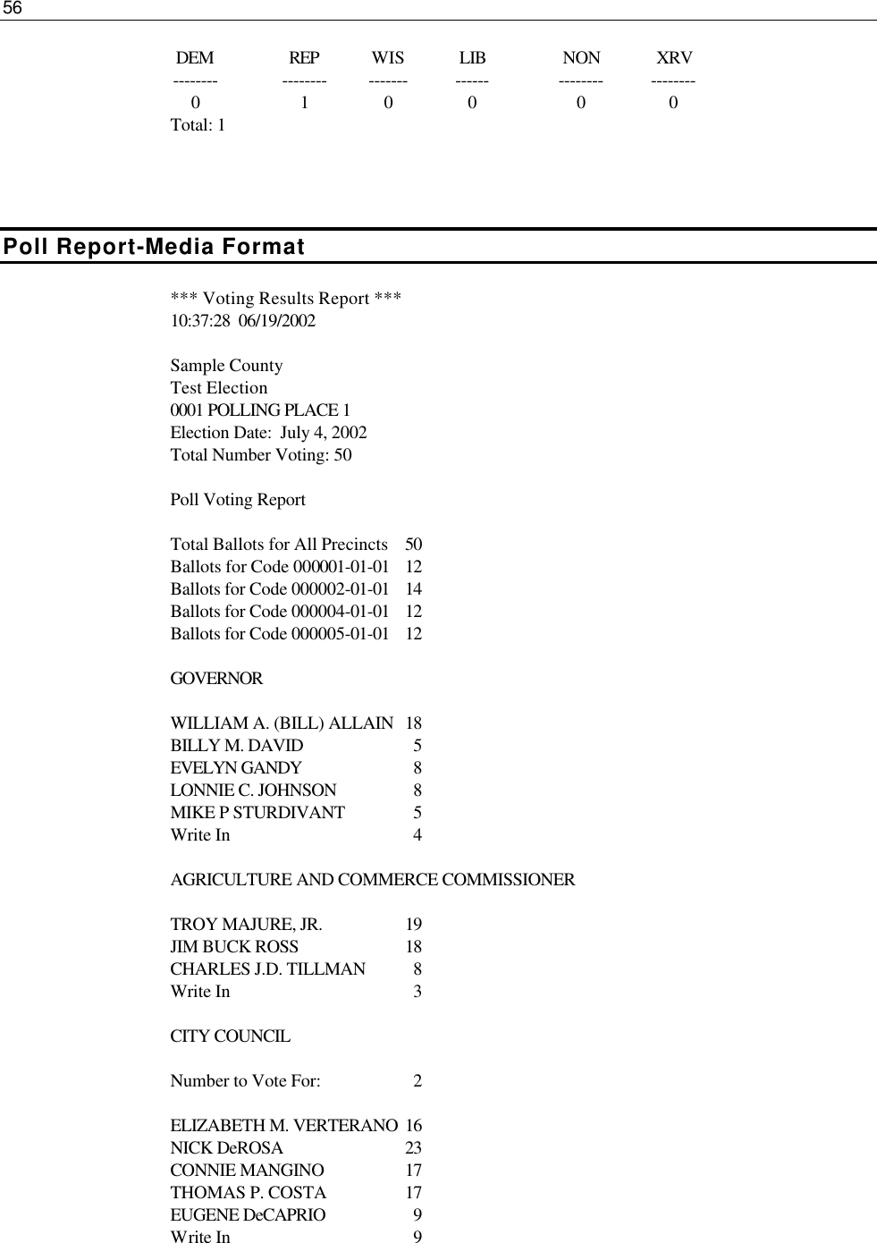
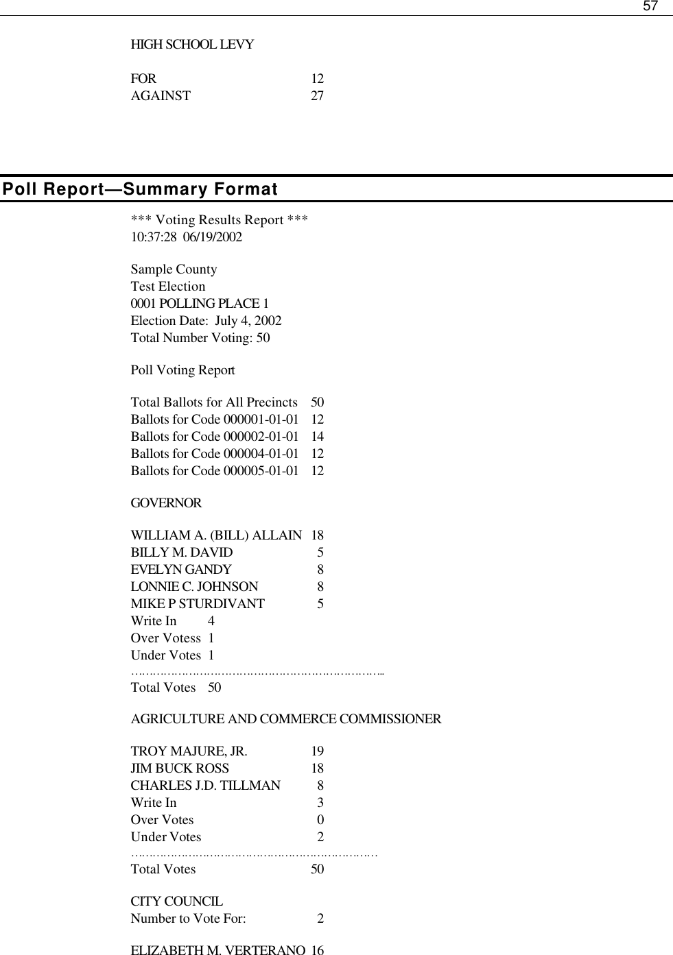
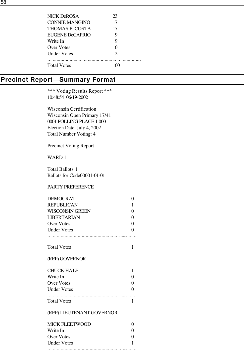
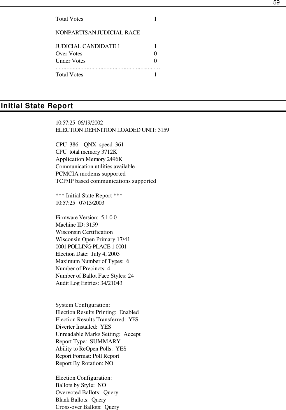
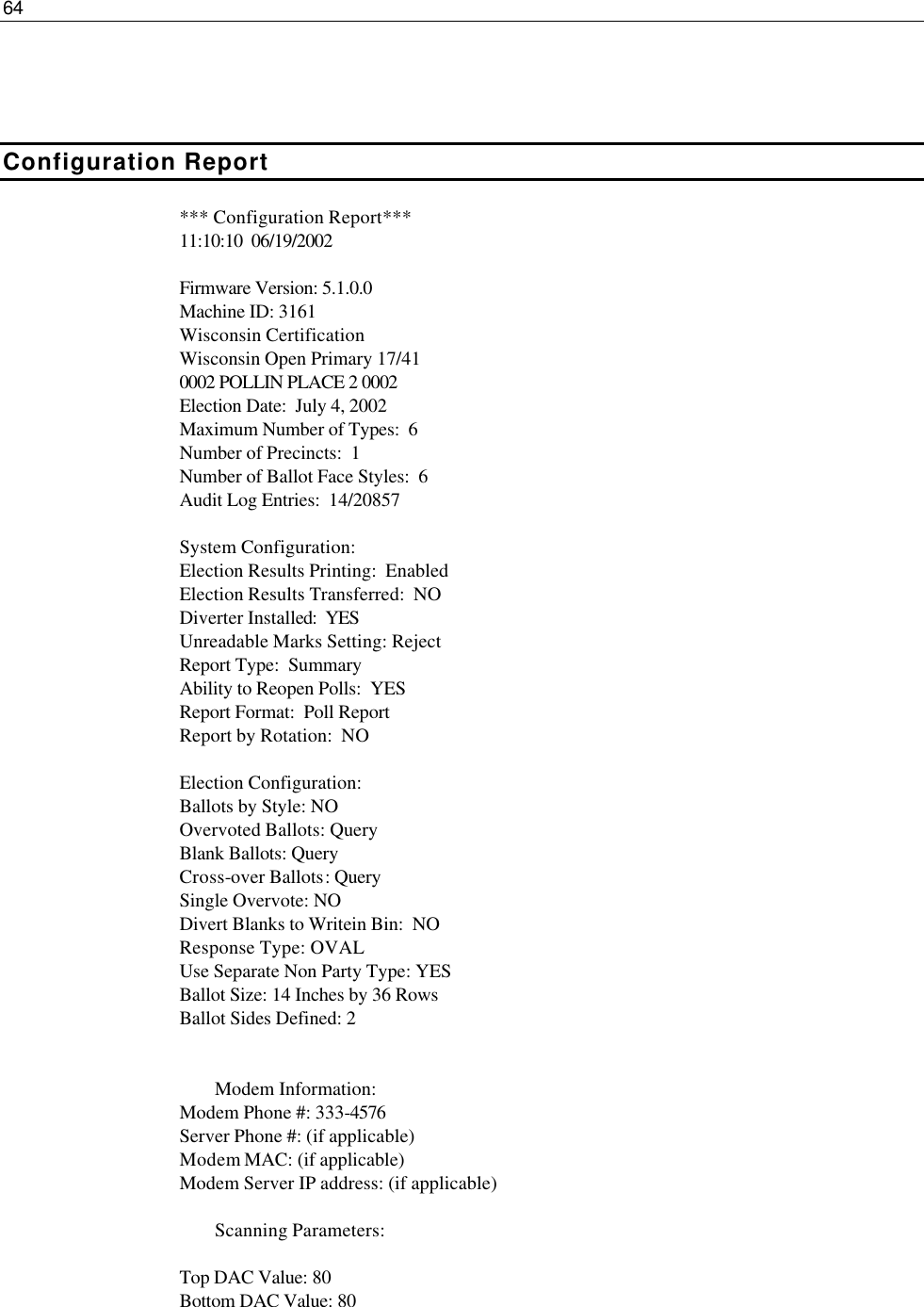
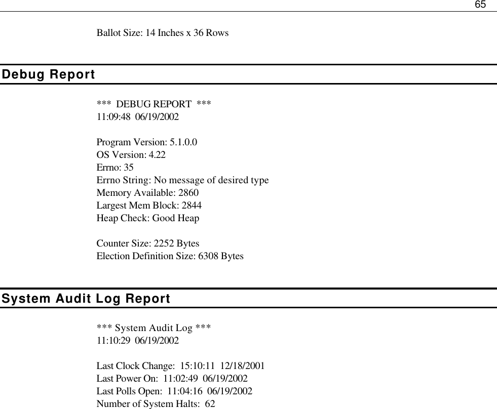
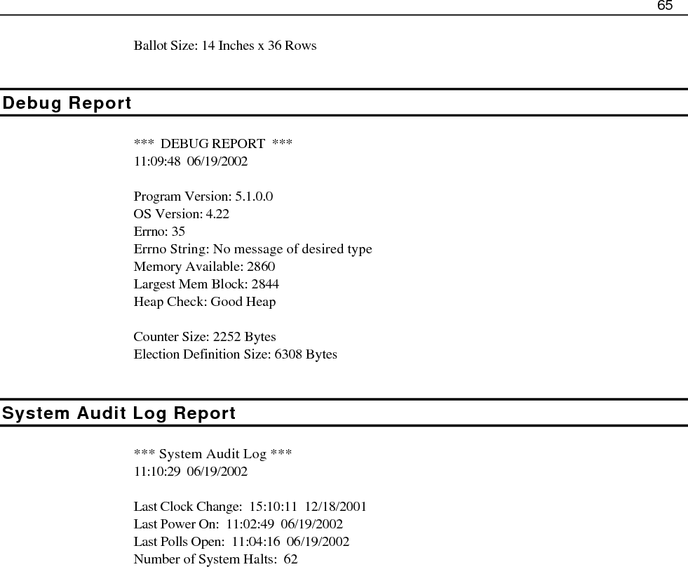
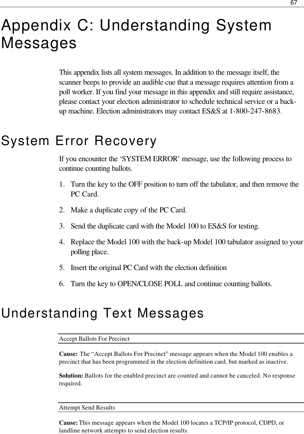
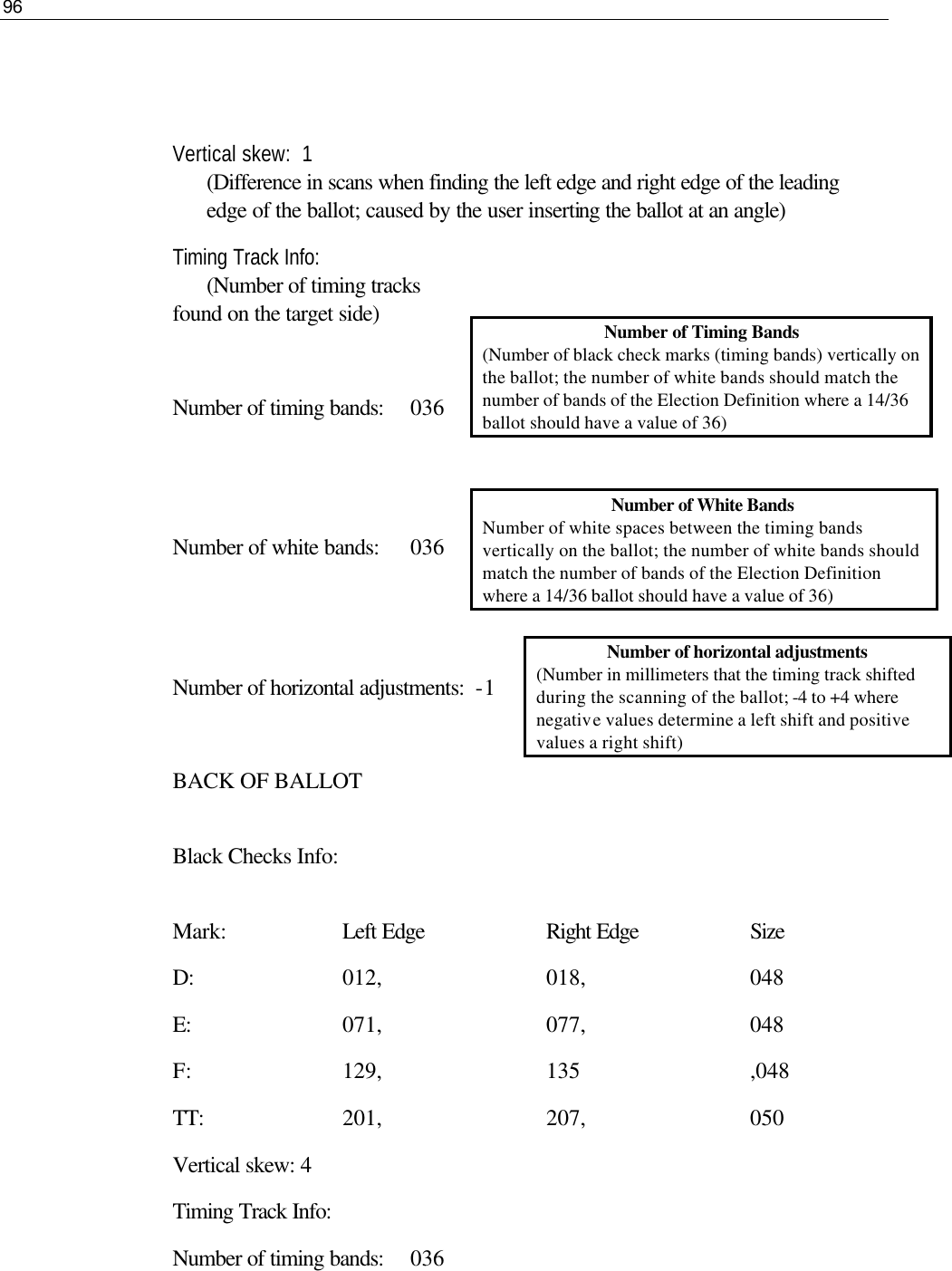
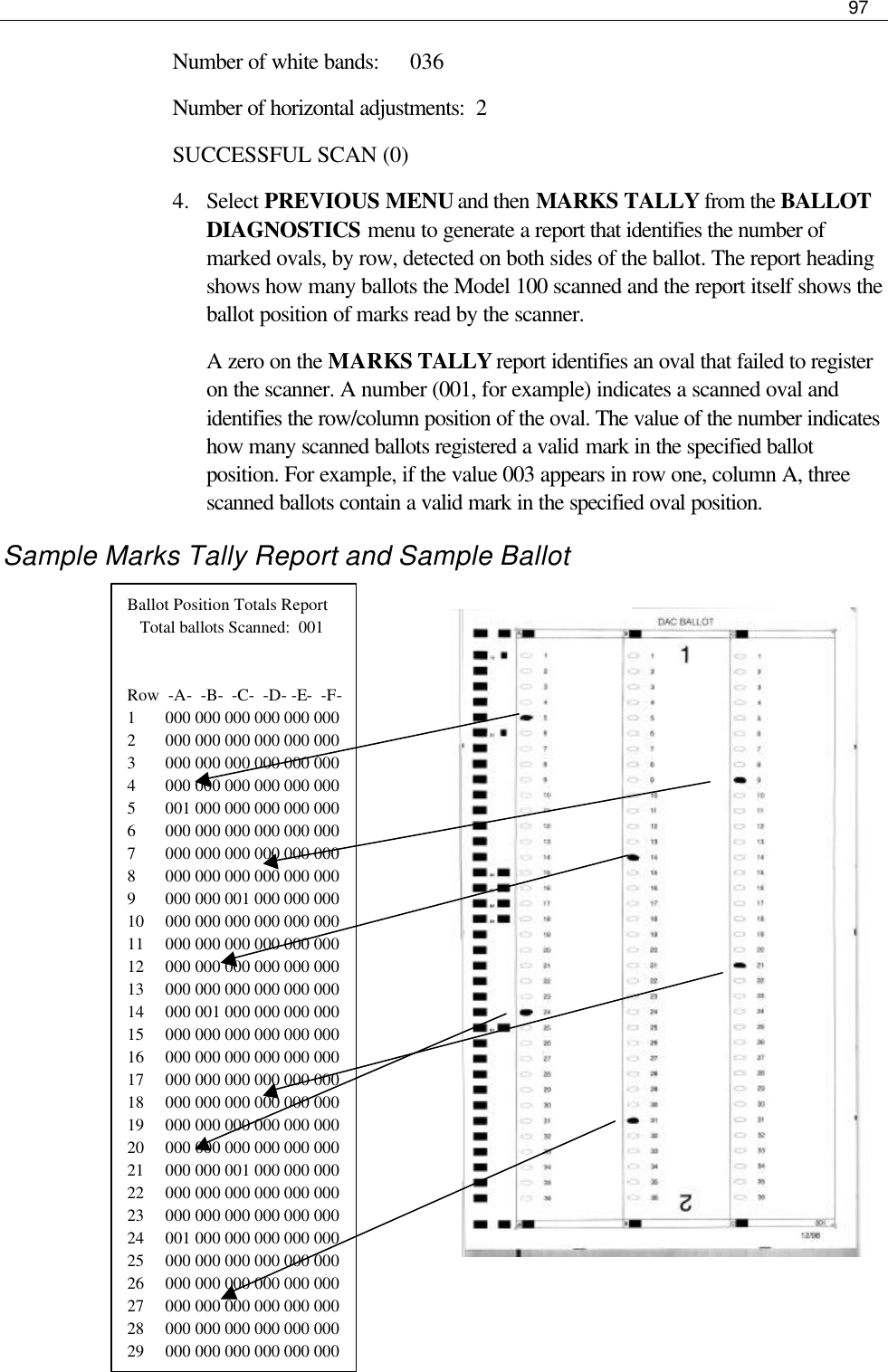
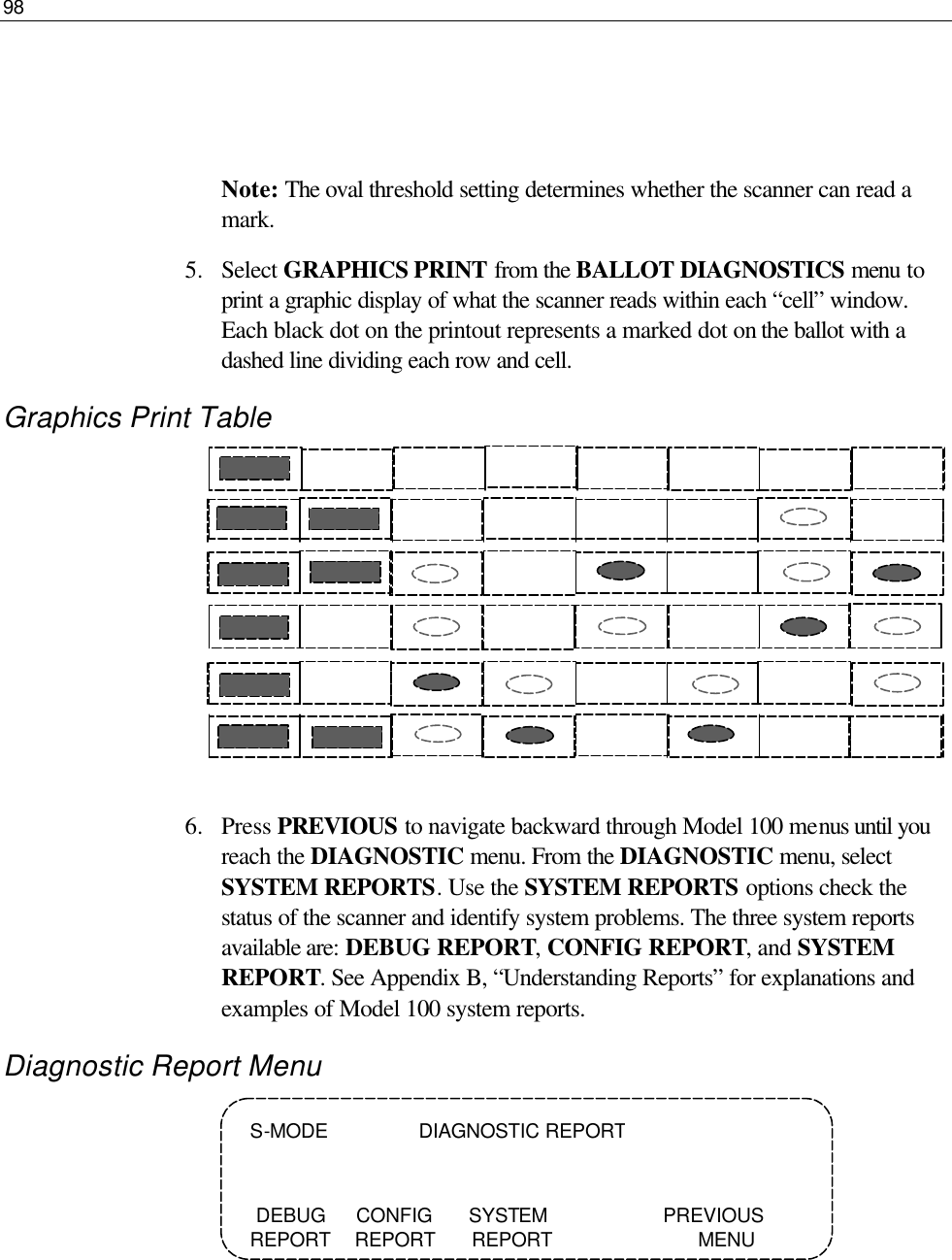
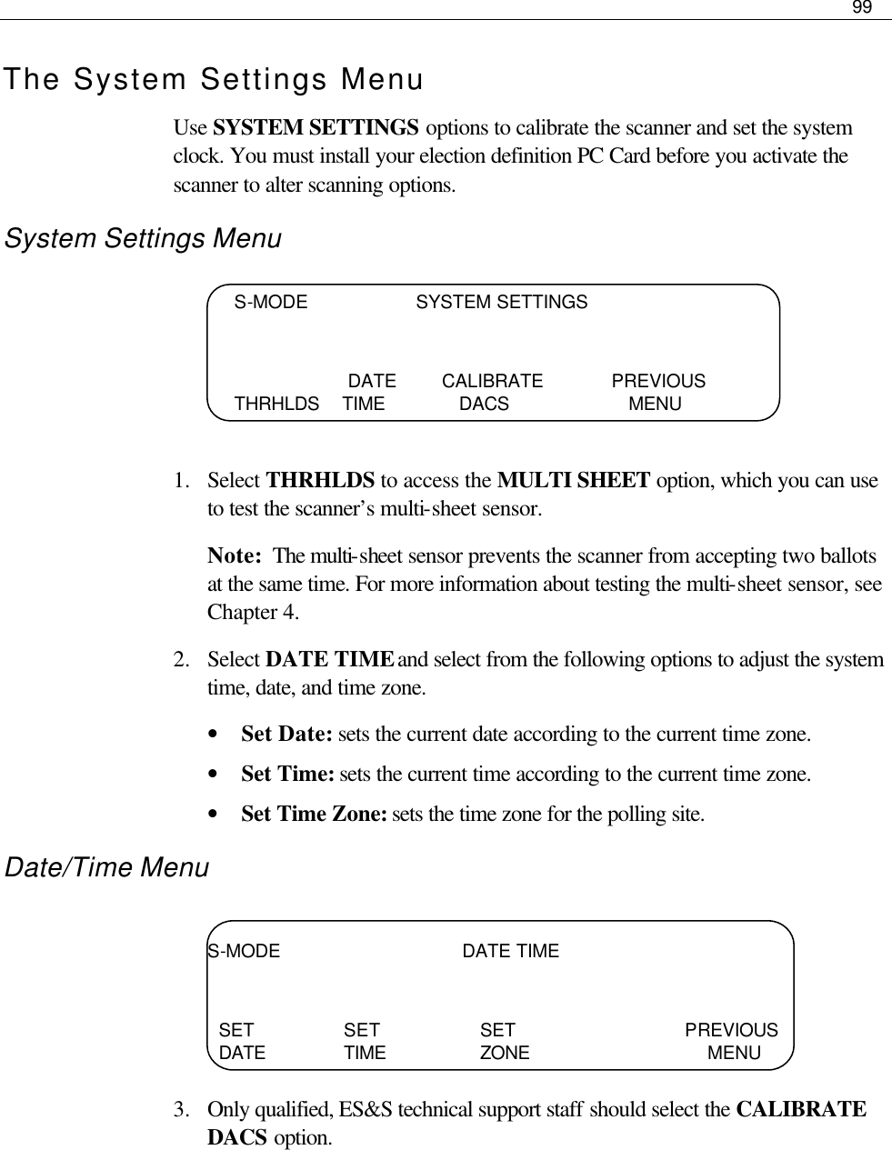
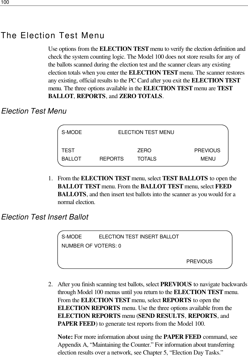
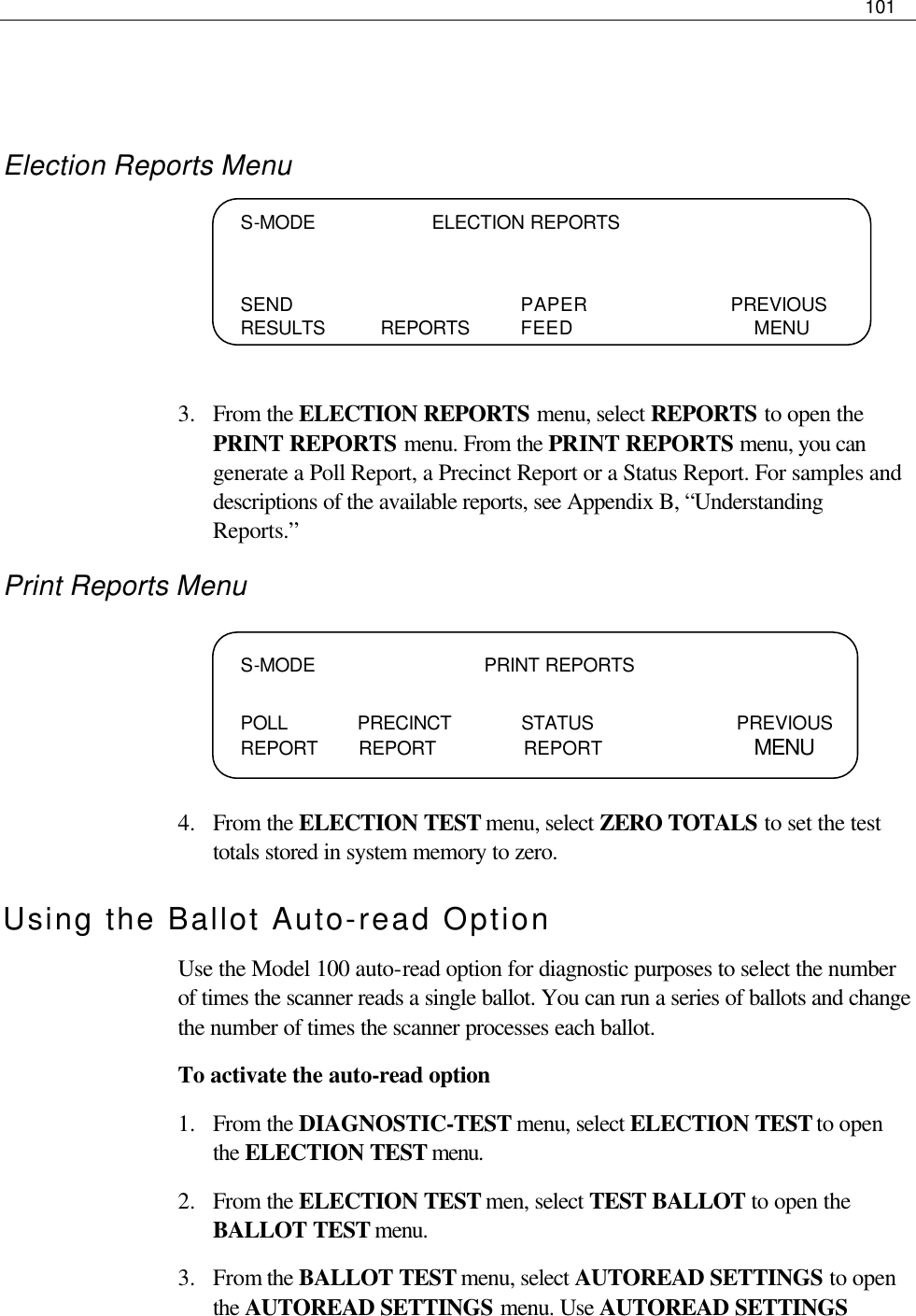
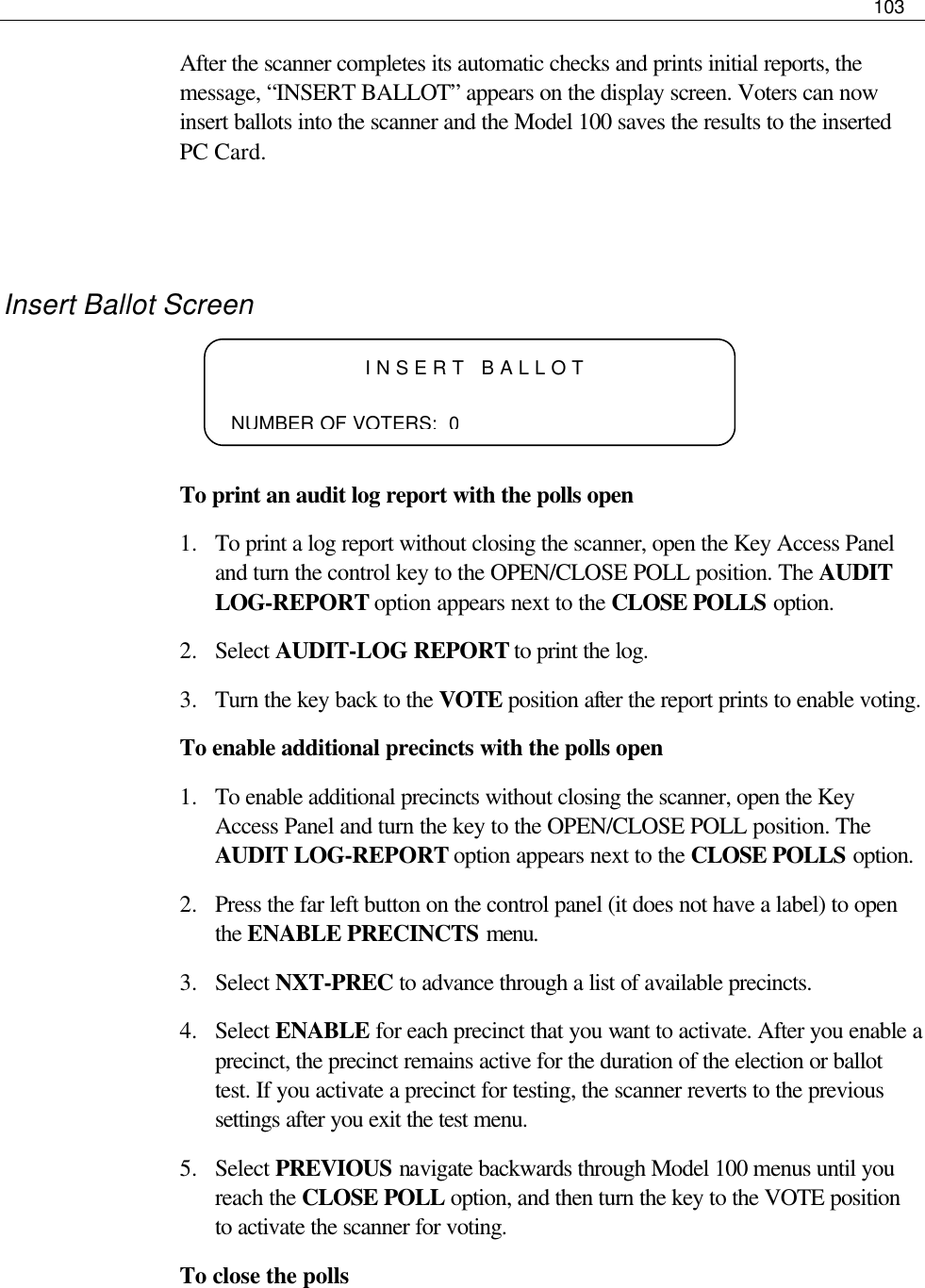
M100 User Manual