Electronic Controls Design E47-6342-45 MEGA M.O.L.E. User Manual A47 6342 00 2 10
Electronic Controls Design Inc MEGA M.O.L.E. A47 6342 00 2 10
Contents
- 1. Quick Reference Guide
- 2. User Manual part 1
- 3. User Manual part 2
- 4. User Manual part 3
User Manual part 3
♦249♦ MEGAM.O.L.E.® Help System Guide
5) Select the firmware file.
6) Click the Open command button to start updating the firmware.
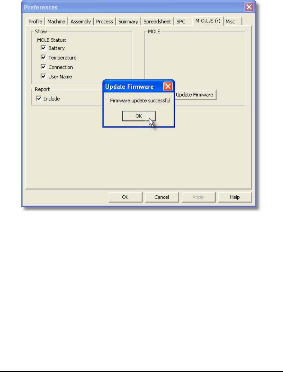
7) When the update firmware process is complete, select the OK command button.
MEGAM.O.L.E.® Help System Guide ♦250♦
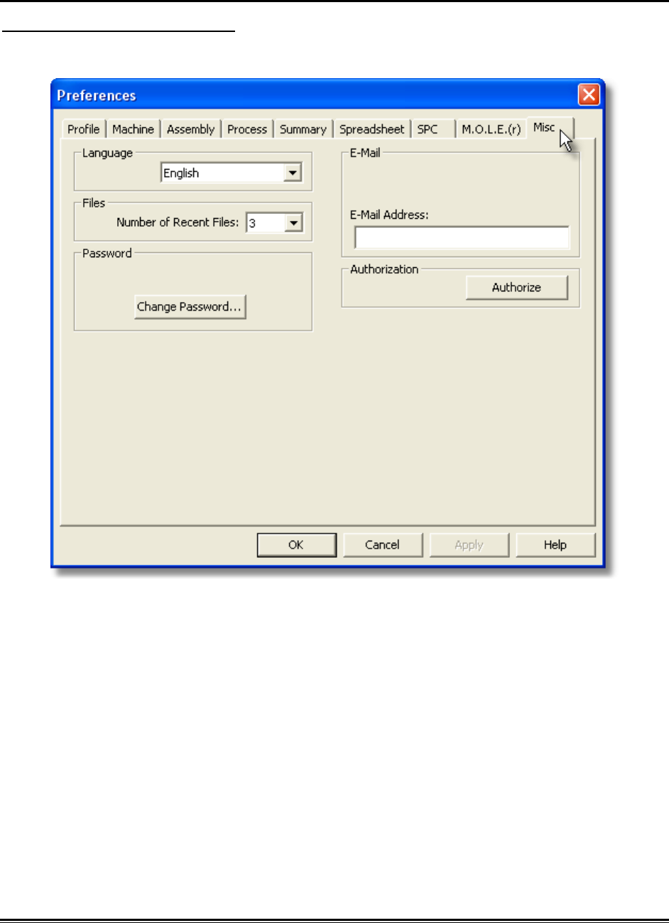
5.5.1.6.9. Misc
To access misc preferences:
1) On the File menu, click Preferences, and then click the Misc tab.
♦251♦ MEGAM.O.L.E.® Help System Guide
Language
This is where the user can change all of the menus and commands to a different
language.
If the language is changed it will require the software to be restarted.
To select a different language:
1) On the File menu, click Preferences, and then click the Misc tab.
2) Select a desired language from the Language drop-down box.
3) Restart the software program.
Files
The most recently selected working directories are displayed at the bottom of the File
menu. The user can select how many recent directories to display.
MEGAM.O.L.E.® Help System Guide ♦252♦
Password
The software has a password protection feature that uses case-sensitive text for
securing access to a Page Tab and the associated preference tab. When password
protection is used, the Page Tab will be highlighted in yellow and the user will not be
able to access the protected worksheet without proper password privileges.
If there are password protected Page Tabs, the password protect command will not
affect data when uploading from the M.O.L.E. profiler. The protected Page Tabs just
cannot be viewed without the password.
To change a password:
1) On the File menu, click Preferences, and then click the Profile tab.
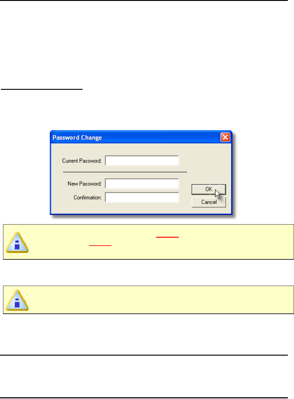
2) In the Password section, click the Change Password command button and the
Password Change dialog box appears.
The software has a default password Admin. When the password is changed
for the first time, Admin will need to be entered in the Current Password text
box.
3) Enter current password in the Current Password text box.
4) Enter a new password in the New Password text box.
The software only accepts passwords with a minimum of 4 characters.
5) Enter the new password again in the Confirmation text box and then click the
OK command button to accept or Cancel to not change the password.
Email
The user can send or save a Screen image (.BMP) or Data Run (.XMG) to an email
recipient. The user can set a default email address to have the software automatically
populate the Email recipient text box when using the Send to command.
♦253♦ MEGAM.O.L.E.® Help System Guide
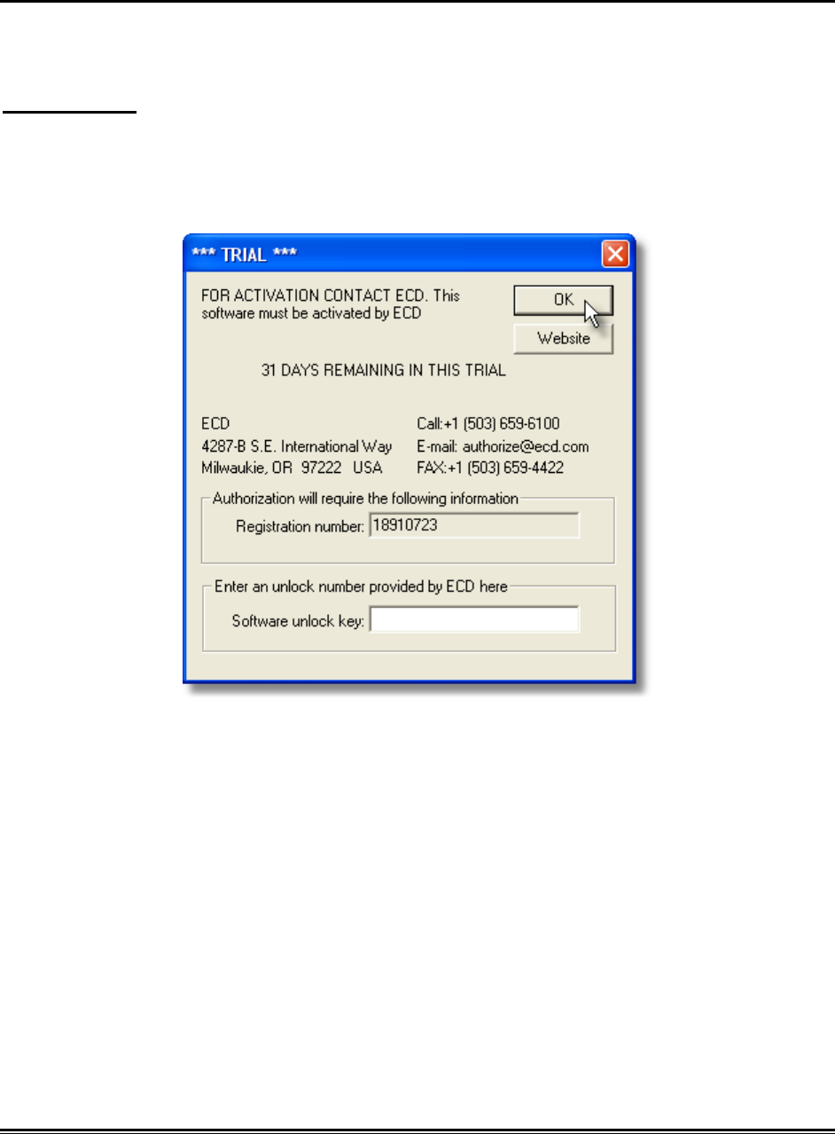
Authorization
The software is a fully functional 30-day trial version. Once the trial period is over, you
may purchase the software from an ECD Salesperson.
To authorize:
1) On the File menu, click Preferences, and then click the Profile tab.
2) In the Authorization section, click the Authorize command button and the
Password Change dialog box appears.
3) Enter the purchased Authorization key in the text box and click the OK command
button.
MEGAM.O.L.E.® Help System Guide ♦254♦
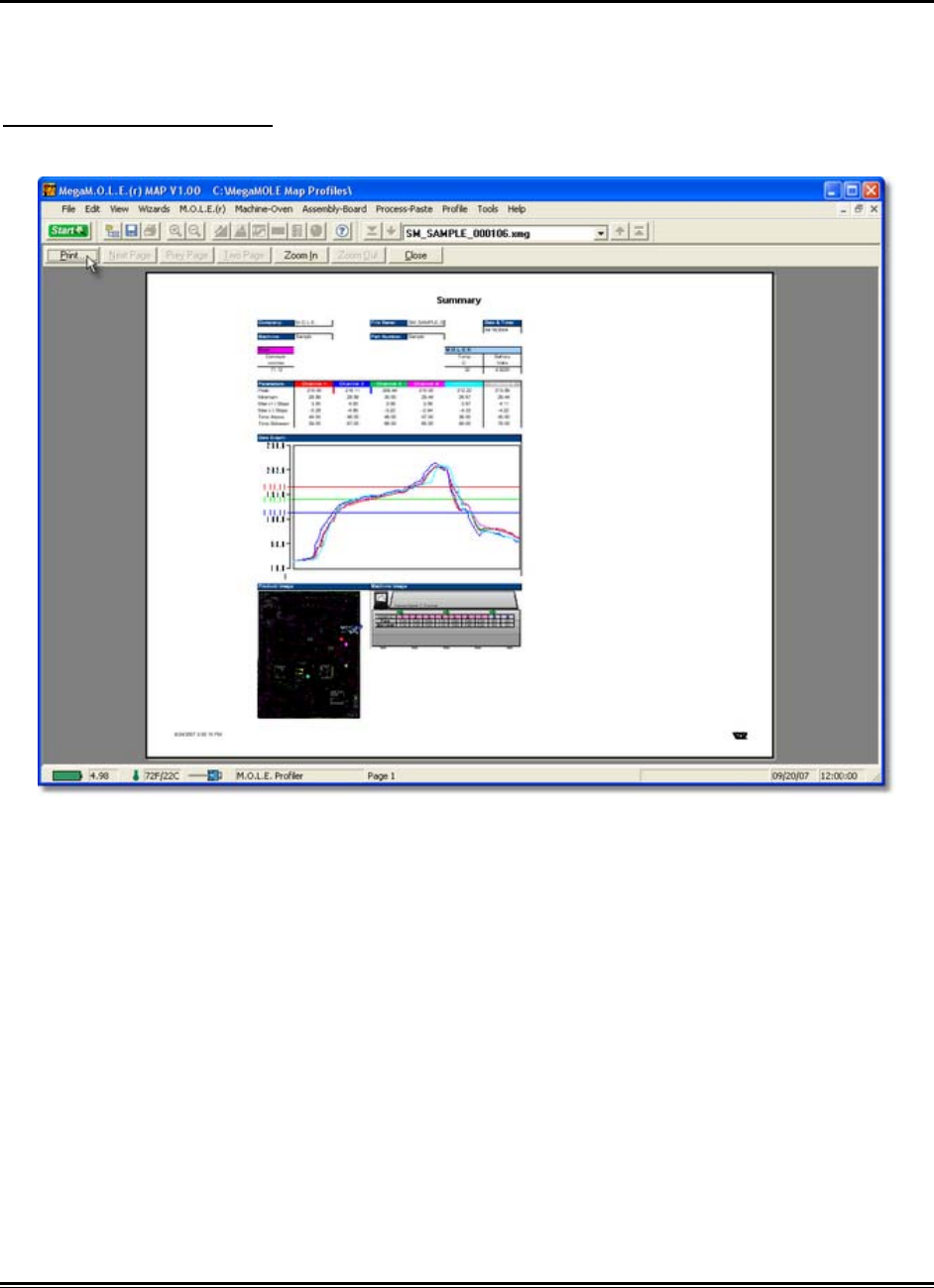
5.5.1.7. Print Preview
The Print Preview command shows a preview of the page(s) to be printed. This
command is useful when confirming print options.
To view a print preview:
1) On the File menu, click Print Preview.
2) Use the buttons on the toolbar to look over the page or make adjustments before
printing.
♦255♦ MEGAM.O.L.E.® Help System Guide
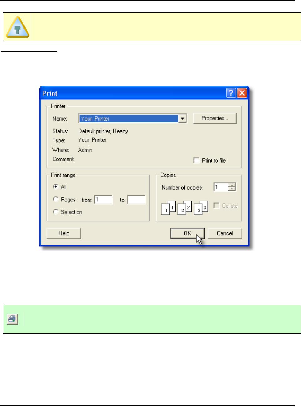
5.5.1.8. Print Page Tab
The Print Page Tab command prints the currently displayed Page Tab.
The options that appear on the Print dialog box will depend on the type of
printer and the installed printer driver.
To print a page:
1) On the File menu, click Print.
2) Select desired print options.
3) Click the OK command button to close the Print dialog box and initiate printing or
Cancel to quit the command.
This command can be accessed on the Toolbar and can also be used by pressing the
shortcut keys [CTRL + P].
Print Page Tab Button
MEGAM.O.L.E.® Help System Guide ♦256♦
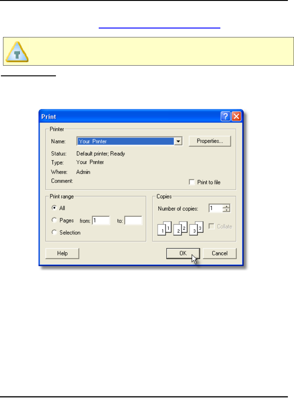
5.5.1.9. Print Report
The Print Report command prints all of the individual Page Tabs in a report format. The
Page Tabs included in the Print Report command can be configured on the associated
Preference tab. Refer to topic Software>Menus>File>Preferences for more
information.
The options that appear on the Print dialog box will depend on the type of
printer and the installed printer driver.
To print a page:
1) On the File menu, click Print Report.
2) Select desired print options.
3) Click the OK command button to close the Print dialog box and initiate printing or
Cancel to quit the command.
♦257♦ MEGAM.O.L.E.® Help System Guide
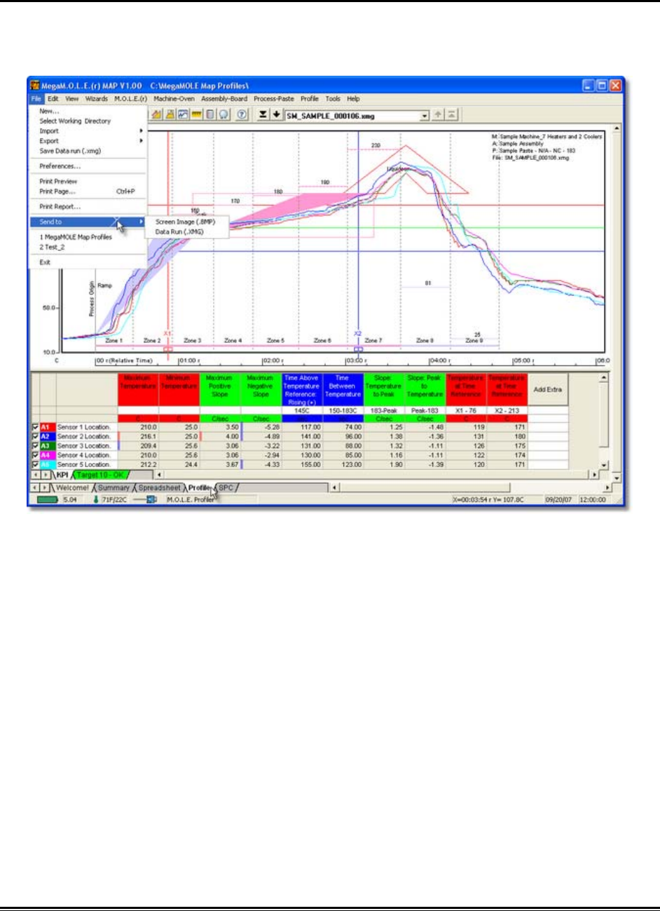
5.5.1.10. Send to
The Send to commands let the user send or save a Screen image (.BMP) or Data Run
(.XMG) to an email recipient or file folder. This command is useful when the user would
like to share profile data with other locations or when troubleshooting problems.

MEGAM.O.L.E.® Help System Guide ♦258♦
5.5.1.10.1. Screen Image
To send a screen image:
1) Launch an email program (i.e. Outlook, Firefox, Endora).
2) On the File menu, point to Send to Mail Recipients then select Screen Image
to capture a bitmap (.BMP) image of the displayed Page Tab screen.
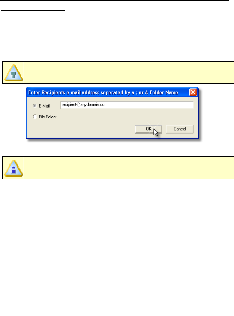
3) In the Send to dialog box select Email or File Folder.
4) Enter an email address or navigate to a file folder.
When sending a file to multiple recipients, all email addresses must be
separated by a semicolon (;).
5) Click the OK command button to finish or Cancel to quit the command.
When sending files, the email program may display an message dialog that
informs the user that it is sending the email.
♦259♦ MEGAM.O.L.E.® Help System Guide
5.5.1.10.2. Data Run
To send a data run file:
1) Launch an email program (i.e. Outlook, Firefox, Endora).
2) On the File menu, point to Send to Mail Recipients then select Data Run to
send or save the currently selected data run (.XMG).
3) In the Send to dialog box select Email or File Folder.
4) Enter an email address or navigate to a file folder.
When sending a file to multiple recipients, all email addresses must be
separated by a semicolon (;).
5) Click the OK command button to finish or Cancel to quit the command.
When sending files, the email program may display an message dialog that
informs the user that it is sending the email.
MEGAM.O.L.E.® Help System Guide ♦260♦
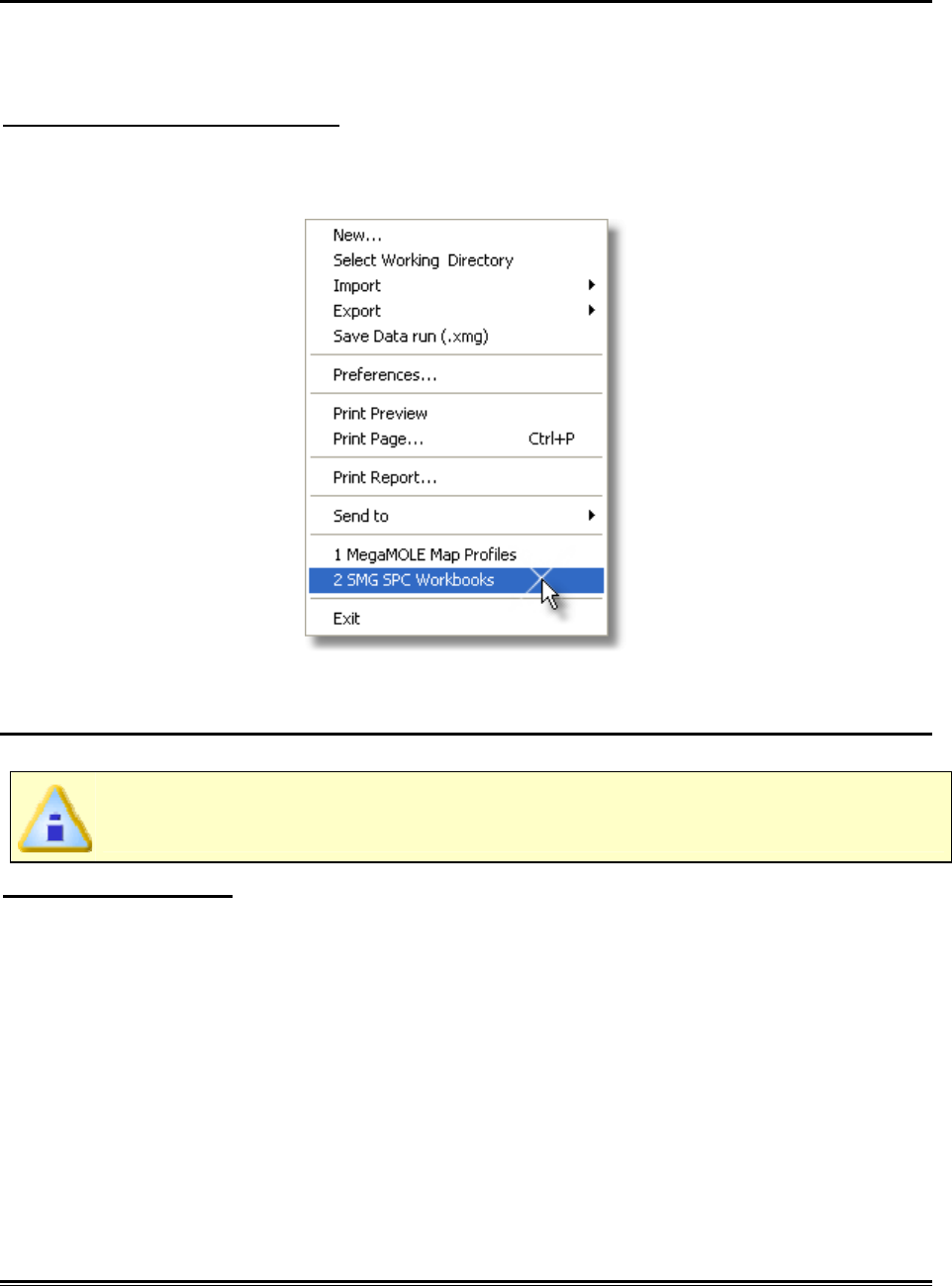
5.5.1.11. Recent Working Directory
The most recently selected working directories are displayed at the bottom of the File
menu.
To select a working directory:
1) On the File menu, click the name of the desired directory or press the
appropriate number beside it.
5.5.1.12. Exit
The Exit command closes the software program.
When exiting the software, any changes made to the currently selected data
run will automatically be saved.
To exit the program:
1) On the File menu, click Exit to quit the program.
♦261♦ MEGAM.O.L.E.® Help System Guide
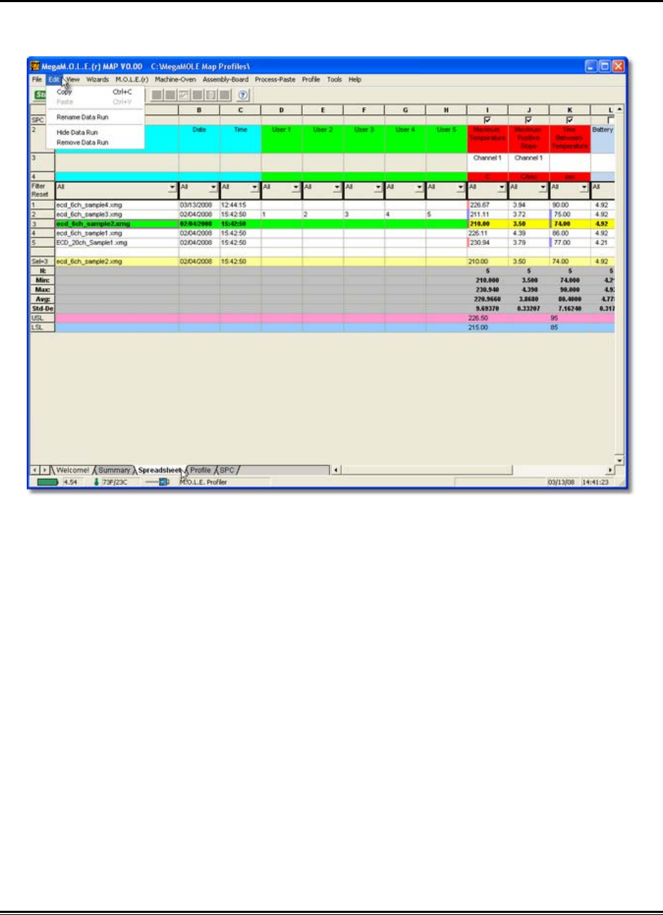
5.5.2. Edit Menu
The Edit menu commands enable the user manage the data run set displayed on the
Spreadsheet to so the most beneficial data is assembled in the working directory.

MEGAM.O.L.E.® Help System Guide ♦262♦
5.5.2.1. Copy
To copy data:
1) Select the Spreadsheet Page Tab.
2) Highlight a Spreadsheet data run row or individual cell.
3) On the Edit menu, click Copy to copy the data in the selected Spreadsheet cells
for pasting into other user definable cells or different programs.
This command can also be used by pressing the shortcut keys [CTRL +C].
♦263♦ MEGAM.O.L.E.® Help System Guide
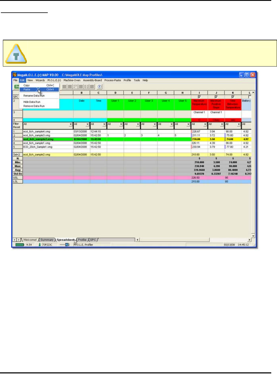
5.5.2.2. Paste
To paste data:
1) Select the Spreadsheet Page Tab.
2) Highlight a user definable cell.
User definable cells have label headers of User 1-5 and are colored green.
3) On the Edit menu, click Paste, to paste the data in the selected Spreadsheet
cells.
This command can also be used by pressing the shortcut keys [CTRL +V].
MEGAM.O.L.E.® Help System Guide ♦264♦
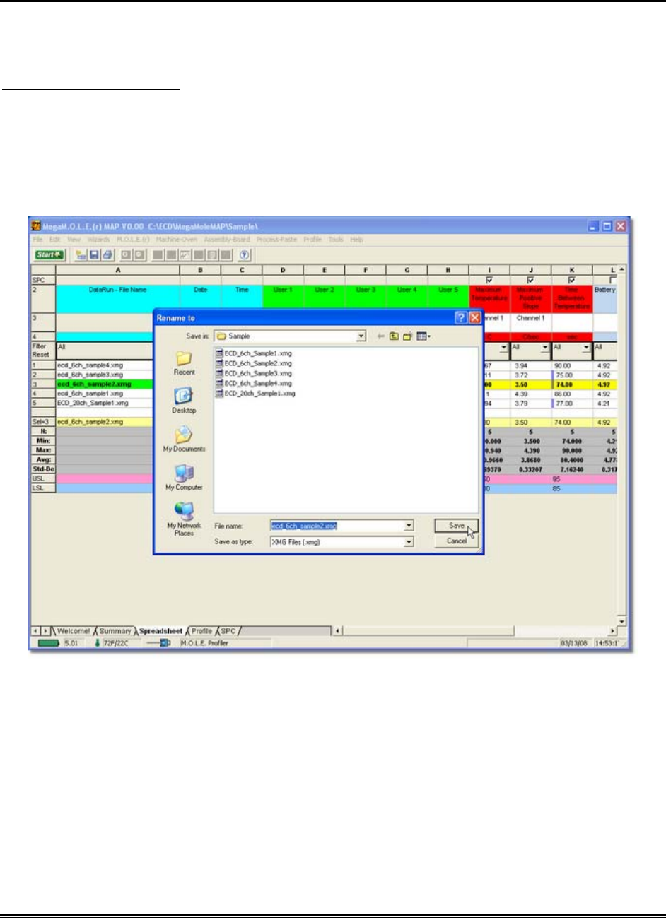
5.5.2.3. Rename Data Run
Since the software is a data run manager, the user can rename the data run files
displayed on the Spreadsheet Page Tab.
To rename a data run:
1) Select the Spreadsheet Page Tab.
2) Highlight a Spreadsheet data run.
3) On the Edit menu, click Rename Data Run and the software will prompt the user
to specify a new data run file name.
4) Rename the data run file.
5) Click the Save command button to rename the file or Cancel to quit the
command.
♦265♦ MEGAM.O.L.E.® Help System Guide
5.5.2.4. Hide Data Run
The Hide Data Run excludes a data run row without eliminating it completely from the
working directory. This command is similar to the filter function, and is helpful when data
runs may not be beneficial to the data run set statistics.
To hide a data run:
1) On the Edit menu, click Hide Row.
The data run is now excluded from the data run set without eliminating it completely
from the working directory.
To restore hidden data set row(s) click the Red Filter Reset button located on
the Spreadsheet Page Tab. Refer to topic Software>Page
Tabs>Spreadsheet>Filtersfor more information.
5.5.2.5. Remove Data Run
Since the software is a data run manager, the user can remove data runs selected
working directory displayed on the Spreadsheet Page Tab.
When a data run is removed the software automatically creates a backup
(.BAK) file of the removed data run. To restore, navigate to the working
directory, rename the (*.BAK) file extension to the MAP software (.XMG) file
extension.
To remove a data run:
1) On the Edit menu, click Remove Data Run to remove a data run that is not
wanted. This command is helpful when data has been collected and the user
feels it is not beneficial to the data run set or is corrupted.
MEGAM.O.L.E.® Help System Guide ♦266♦
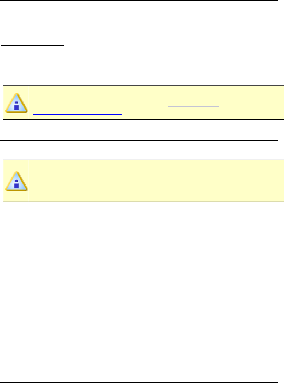
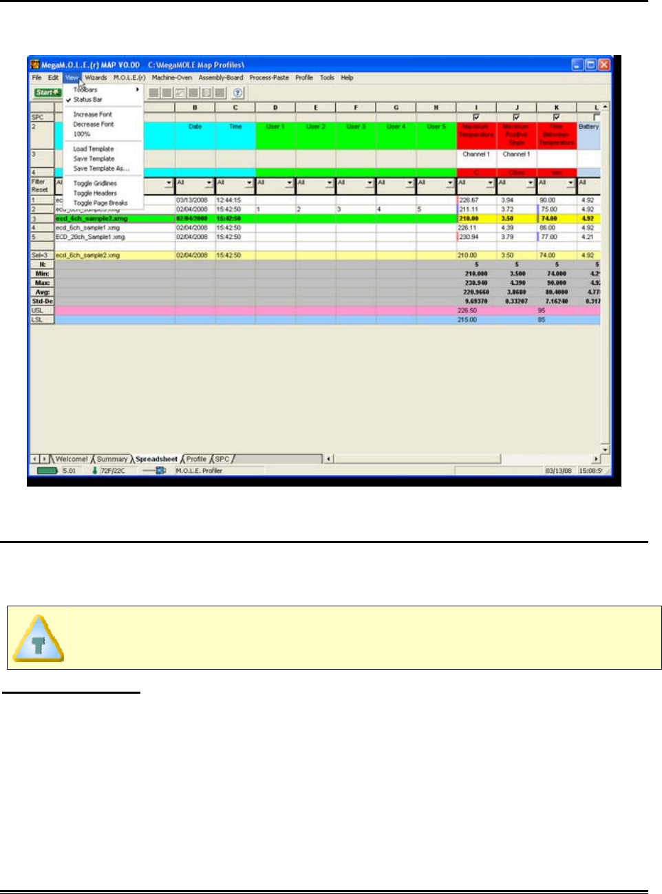
5.5.3. View Menu
The View menu commands enable the user to manipulate which areas are viewed on
the standard Page Tabs and Templates.
5.5.3.1. Toolbars
By default, the Standard and Navigate toolbars appear docked on a single row, showing
the toolbar buttons that are used most often. When there is a check mark beside the
toolbar command it indicates that that it is displayed.
The toolbars can be moved to other edges of the program window. To move,
drag docked toolbar until the toolbar snaps into place on the desired edge.
To hide a toolbar:
1) On the View menu, point to Toolbar then select the desired toolbar to display or
hide.
♦267♦ MEGAM.O.L.E.® Help System Guide
5.5.3.2. Status Bar
By default, the Status bar appears along the bottom of the program window. When there
is a check mark beside the toolbar command it indicates that that it is displayed.
To display the status bar:
1) On the View menu, click Status bar to display or hide the Status bar.
5.5.3.3. Increase Font
The Increase Font command has the capability to zoom the current Page Tab in
multiple times.
To Increase Font:
1) On the View menu, click Increase Font to make the current Page Tab view
larger. When the maximum Increase Font level has been reached the command
will be dimmed.
The Increase Font command can be accessed on all Page Tabs excluding the
Profile Page Tab.
5.5.3.4. Decrease Font
The Decrease Font command has the capability to zoom the current Page Tab out
multiple times.
To Decrease Font:
1) On the View menu, click Decrease Font to make the current Page Tab view
smaller. When the maximum Decrease Font level has been reached the
command will be dimmed.
The Decrease Font command can be accessed on all Page Tabs excluding the
Profile Page Tab.
MEGAM.O.L.E.® Help System Guide ♦268♦
5.5.3.5. 100%
The Zoom 100% command restores the current Page Tab to the default view level.
To zoom 100%:
1) On the View menu, click 100% to restore current Page Tab view to the default.
The 100% command can be accessed on all Page Tabs excluding the Profile
Page Tab.
5.5.3.6. Load Template
When a template data calculation has been changed or a new one has been added, the
user can use the load template to refresh the default template specified in
Software>Menus>File>Preferences.
To load a template:
1) On the View menu, click Load Template to load the default template.
This command can also be accessed by right-clicking over a template.
5.5.3.7. Save Template
When a template data calculation has been changed or a new one has been added, the
user can save the calculations to the default template specified in
Software>Menus>File>Preferences.
To save a template:
1) On the View menu, click Save Template to save the default template.
This command can also be accessed by right-clicking over a template data
calculation.
♦269♦ MEGAM.O.L.E.® Help System Guide
5.5.3.8. Save Template As...
When a template data calculation has been changed or a new one has been added, the
user can save the calculations to a new template file. This is useful when the user would
like to customize a template leaving the default template the same. The user can load
this new template by changing the default template specified in
Software>Menus>File>Preferences.
To save a new template:
1) On the View menu, click Save Template As and the Save Data Calculation
Template dialog box appears.
2) Specify a new file name.
3) Click the Save command button to save the new template file or Cancel to quit
the command.
This command can also be accessed by right-clicking over a template.
5.5.3.9. Toggle Gridlines
The Summary and Spreadsheet Page Tabs are built with cells that are organized into
columns and rows. The software allows the user to show and hide the cell gridlines as
needed. This command is particularly helpful when customizing the Summary Page Tab
template.
To toggle gridlines:
1) On the View menu, click Toggle Gridlines to show or hide cell gridlines.
This command can also be accessed by right-clicking over the Summary or
Spreadsheet templates.
MEGAM.O.L.E.® Help System Guide ♦270♦
5.5.3.10. Toggle Headers
The Summary and Spreadsheet Page Tabs are built with cells that are organized into
columns and rows. These columns and rows include row headings which are numbers
that appear on the left of each row, and column headings which are the letters that
appear at the top of each column.
To toggle headers:
1) On the View menu, click Toggle Headers to show or hide column and row
headers.
This command can also be accessed by right-clicking over the Summary or
Spreadsheet templates.

♦271♦ MEGAM.O.L.E.® Help System Guide
5.5.3.11. Toggle Page Breaks
As data calculations get added to the Spreadsheet Page Tab, it may increase the
amount of pages when printing. The software includes a preview of where page breaks
occur.
To toggle page breaks:
1) On the View menu, click Toggle Page Breaks to show or hide the page break
lines.
This command can also be accessed by right-clicking over the Spreadsheet
template.
MEGAM.O.L.E.® Help System Guide ♦272♦
5.5.4. Wizards Menu
MAP software wizards help guide the user through the most common multi-step tasks.
♦273♦ MEGAM.O.L.E.® Help System Guide
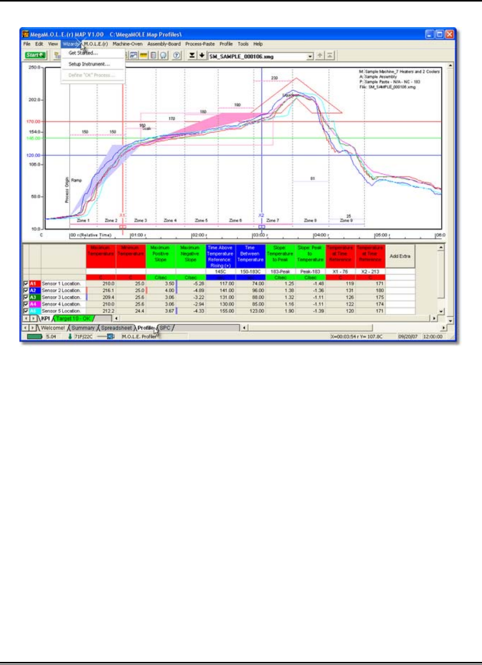
5.5.4.1. Get Started
This command activates the Get Started dialog box for access to the New (Start)
command.
To activate the Get Started dialog box:
1) On the Wizards menu, click Get Started and a dialog box appears with the New
(Start) command button.
5.5.4.2. Setup Instrument
This Wizard guides the user through a typical process on how to set a M.O.L.E. Profiler
up for performing a data run.
1) Connect the M.O.L.E. to the PC. Refer to Basics>Setup>Communications
Setup for more information.
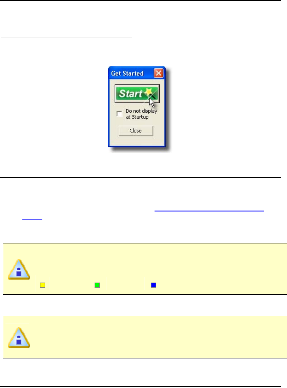
2) On the Wizards menu, click Setup Instrument and the workflow wizard
appears.
When navigating through the wizard, the step list on the left uses a color key
to inform the user of the current step, steps that have been completed and
remaining steps.
Current Completed Remaining
3) Select the desired instrument from the list box. If there is none listed, select the
Scan for Instruments command button to detect all connected instruments.
MAP software allows multiple instruments to be connected to a computer at
one time. Selecting the Scan for Instruments command button will detect all
instruments and display them in the list. If no instrument is detected, the
default Demonstration MEGAM.O.L.E.® profiler is displayed.
MEGAM.O.L.E.® Help System Guide ♦274♦
4) Select the Next command button.
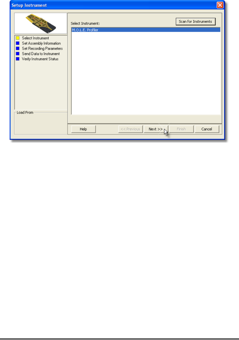
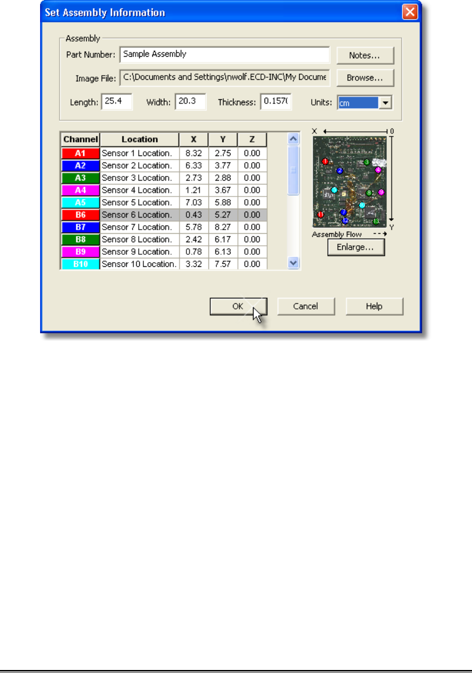
5) Set the assembly information such as part number, board size, sensor locations
and a product image.
♦275♦ MEGAM.O.L.E.® Help System Guide
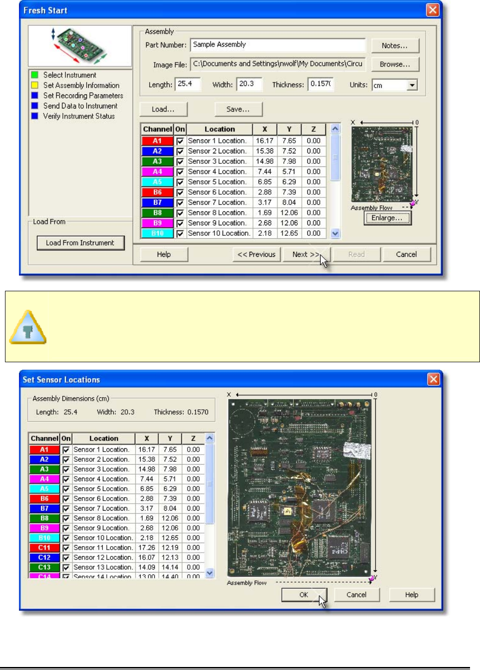
If the user specifies a product image, clicking the Enlarge command button
displays the Set Sensor Locations dialog box where the user can specify the
locations of each sensor. To move sensor locations, drag the sensor markers to
the approximate location where the sensors are attached.
6) Click the Next command button.
MEGAM.O.L.E.® Help System Guide ♦276♦
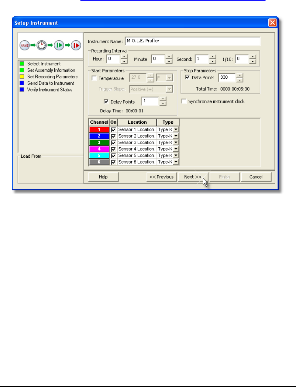
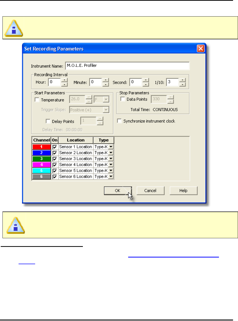
7) Set Recording Parameters such as the instrument name, recording interval, start
parameters and stop parameters. This step is where the user can also turn a
sensor channel ON or OFF, set the sensor location description and sensor type.
Refer to section Software>Menus>MOLE>Set Recording Parametersfor
detailed information for each setting.
8) Select the Next command button.
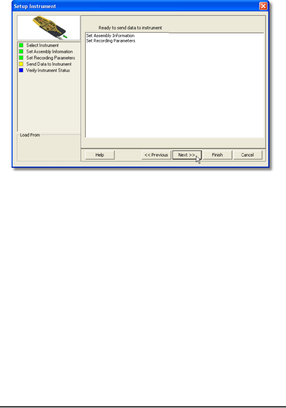
9) Select the Next command button to send the data listed in the dialog box to the
instrument.
♦277♦ MEGAM.O.L.E.® Help System Guide
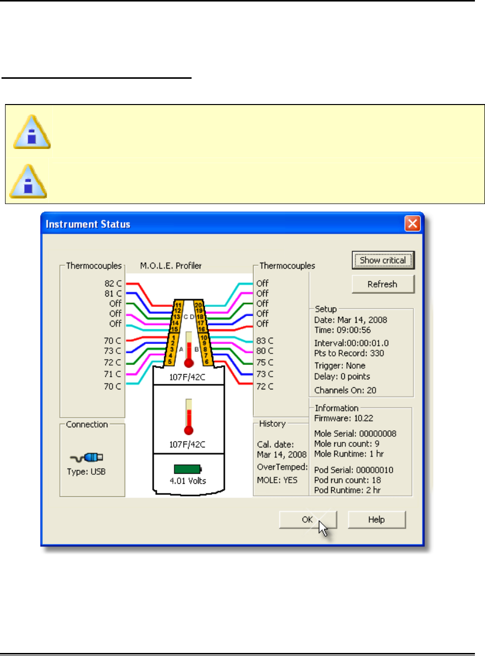
10) Verify the instrument status. This dialog box displays the health of the M.O.L.E.
Profiler such as battery charge, internal temperature, thermocouple
temperatures. If the user selects the Show Critical command button the dialog
box will only display items that will prevent the user from completing a successful
data run.
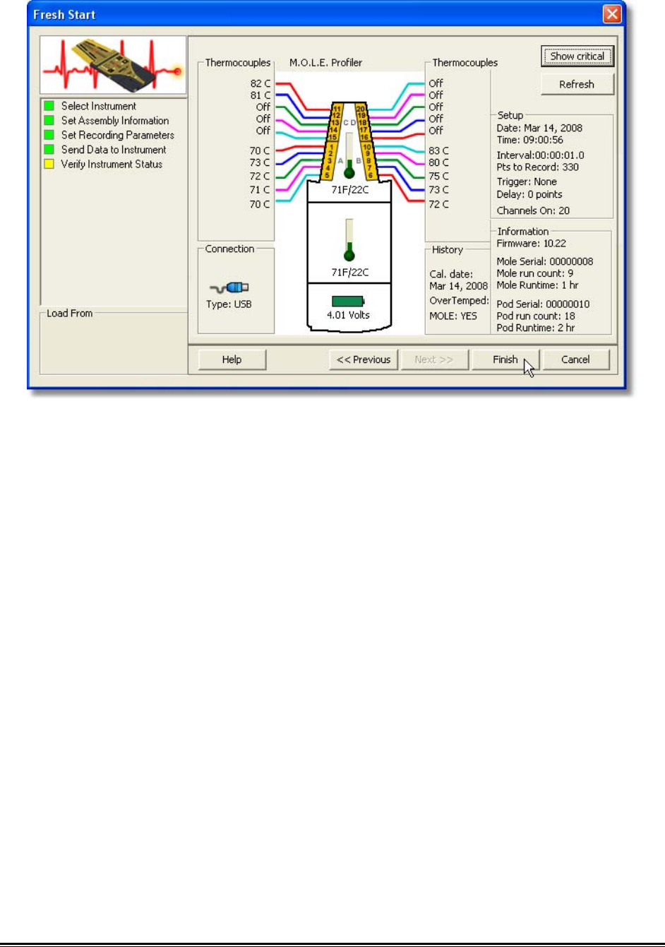
MEGAM.O.L.E.® Help System Guide ♦278♦
11) Select the Finish command button to complete the Setup Instrument wizard.
♦279♦ MEGAM.O.L.E.® Help System Guide
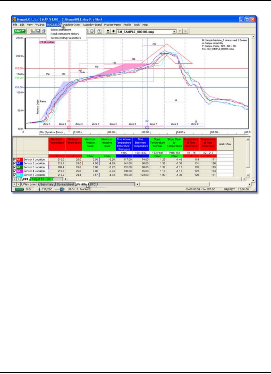
5.5.5. M.O.L.E. Menu
The M.O.L.E. menu commands configure a M.O.L.E. Profiler for collecting process data.
MEGAM.O.L.E.® Help System Guide ♦280♦
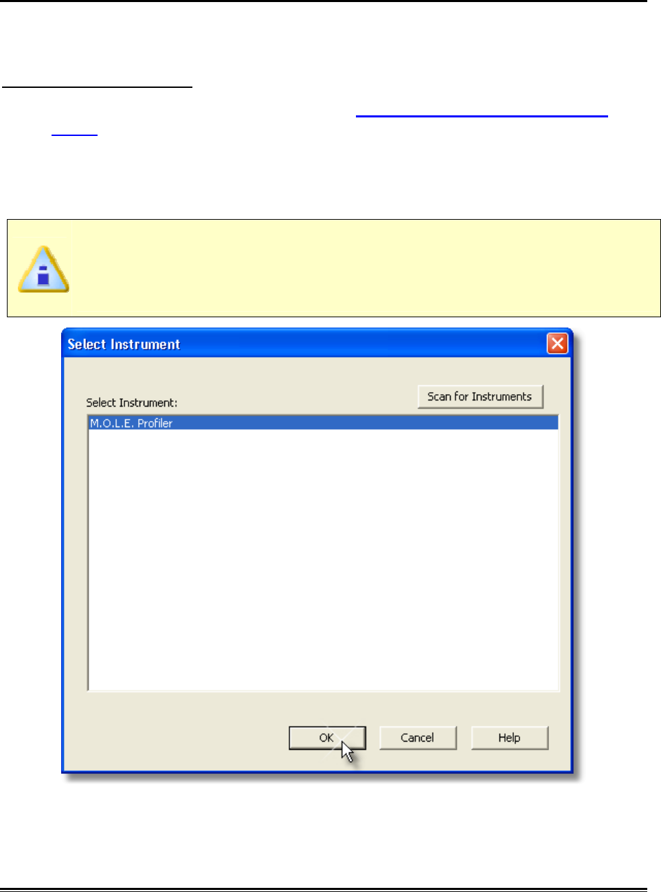
5.5.5.1. Select Instrument
The Select Instrument command allows the user to select an available M.O.L.E. Profiler
to make active so it can interface with the software.
To select an instrument:
1) Connect the M.O.L.E. to the PC. Refer to Basics>Setup>Communications
Setup for more information.
2) On the M.O.L.E. menu, click the Select Instrument command.
3) Select the desired instrument from the list box. If there are none listed, click the
Scan for Instruments command button to detect all available instruments.
MAP software allows multiple instruments to be connected to a computer at
one time. Selecting the Scan for Instruments command button will detect all
instruments and display them in the list. If no instrument is detected, the
default Demonstration MEGAM.O.L.E.® profiler is displayed.
4) Click the OK command button to accept or Cancel to quit the command.
♦281♦ MEGAM.O.L.E.® Help System Guide
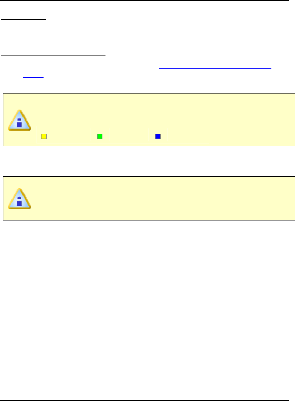
5.5.5.2. Read Instrument
The Download Data workflow is a wizard that starts a new profile (data run) by
downloading the M.O.L.E. Profiler. Once the data run is downloaded, the user can
then choose to apply Machine (Oven), Assembly (Board) and Process (Paste)
information.
The Download Data workflow:
1) Connect the M.O.L.E. to the PC. Refer to Basics>Setup>Communications
Setup for more information.
2) On the M.O.L.E. menu, click Read Instrument.
When navigating through the wizard, the step list on the left uses a color key
to inform the user of the current step, steps that have been completed and
remaining steps.
Current Completed Remaining
3) Select the desired instrument from the list box to make active. If there are none
listed, click the Scan for Instruments command button to detect all available
instruments.
MAP software allows multiple instruments to be connected to a computer at
one time. Selecting the Scan for Instruments command button will detect all
instruments and display them in the list. If no instrument is detected, the
default Demonstration MEGAM.O.L.E.® profiler is displayed.
MEGAM.O.L.E.® Help System Guide ♦282♦
4) Click the Next command button.
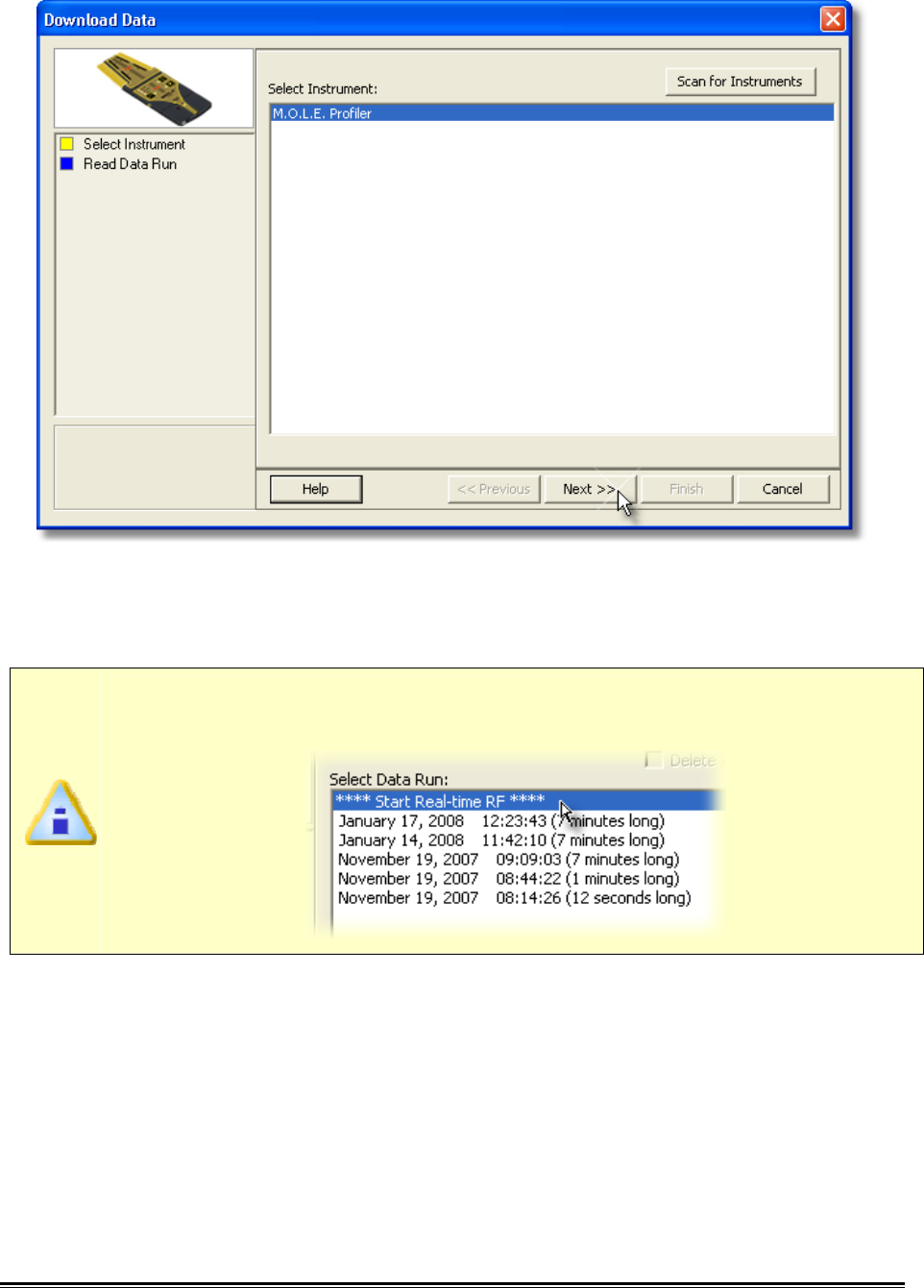
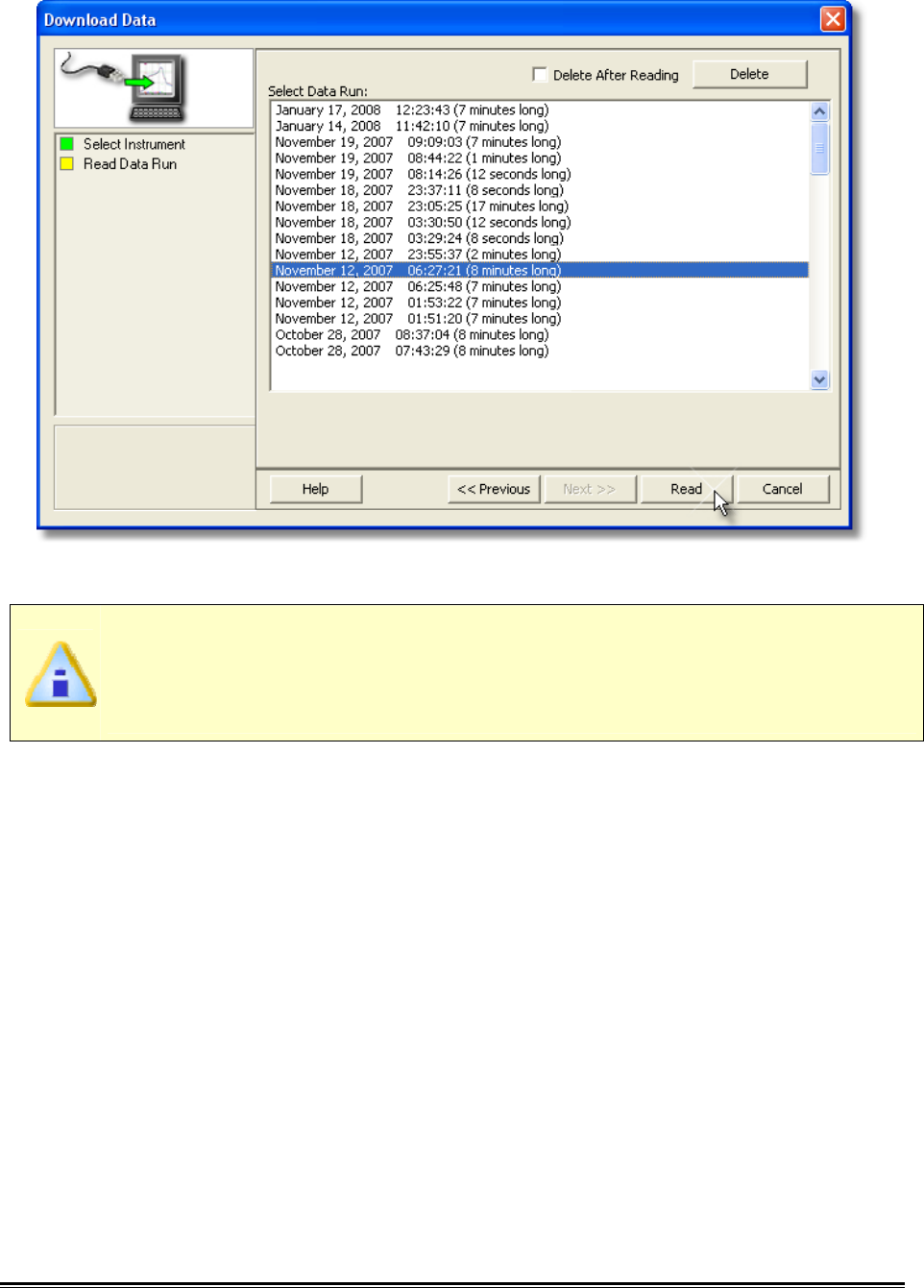
5) Select the desired data run and then click the Read command button to read the
data run from the M.O.L.E. Profiler.
If the user has selected to use the Wireless RF option, select Start real-time
RF on the top of the data run list.
♦283♦ MEGAM.O.L.E.® Help System Guide
On this step of the wizard, the user has the ability to remove a selected data
run from the M.O.L.E. profiler by either selecting the Delete After Reading
check box or selecting the Delete command button and removing it before
downloading.
6) When the data run has been downloaded, the software will prompt the user to
specify a new file name.
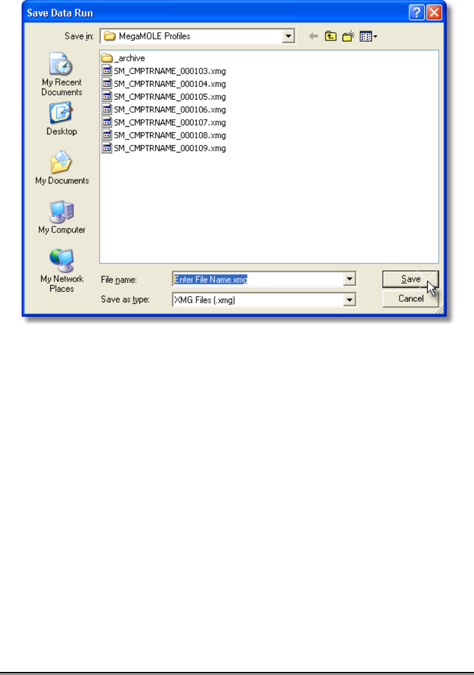
MEGAM.O.L.E.® Help System Guide ♦284♦
I
7) When finished, click the Save command button.
♦285♦ MEGAM.O.L.E.® Help System Guide
5.5.5.3. Instrument Status
This command displays the health of the M.O.L.E. Profiler such as battery charge,
internal temperature, thermocouple temperatures. This command also allows the user
to display items that will prevent the user from completing a successful data run.
To display the instrument status:
1) On the M.O.L.E. menu, click Instrument Status and the dialog box appears.
If an instrument is not currently connected to the computer, the default
Demonstration MEGAM.O.L.E.® profiler will be displayed.
If the I/O module is not connected to the MEGAM.O.L.E.® Profiler, the software
will display a warning message that the instrument is not communicating.
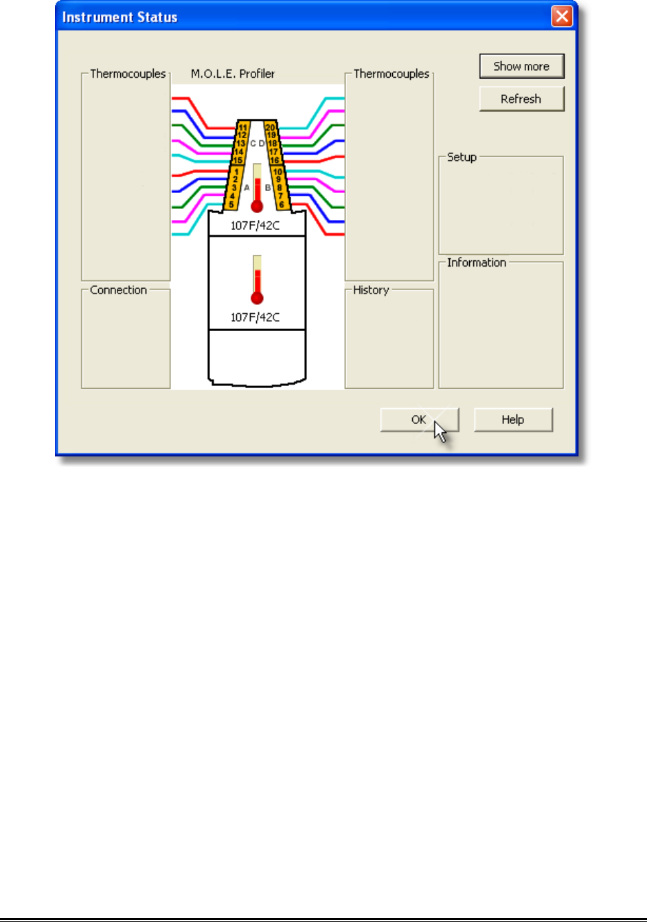
2) Click the Show Critical command button to filter the acceptable status items and
only display critical problems that may prevent the user from completing a data
run. In the example, the internal temperature reported is higher than the
recommended operating specification.
MEGAM.O.L.E.® Help System Guide ♦286♦
3) Click the OK command button to close the dialog box.
♦287♦ MEGAM.O.L.E.® Help System Guide
5.5.5.4. Set Recording Parameters
The Set Recording Parameters command configures how the M.O.L.E. profiler records
data during a data run.
The Start and Stop Parameters are optional settings and do not require
configuration.
If an instrument is not currently connected to the computer, the default
Demonstration MEGAM.O.L.E.® profiler will be displayed.
To set recording parameters:
1) Connect the M.O.L.E. to the PC. Refer to Basics>Setup>Communications
Setup for more information.
2) On the M.O.L.E. menu, click Set Recording Parameters.
3) In the Instrument Name text box, type a company, operator, or M.O.L.E. Profiler
name.
4) Enter the Recording interval at which the M.O.L.E. profiler records data points.
MEGAM.O.L.E.® Help System Guide ♦288♦
5) If desired, configure a Start Parameter such as a threshold temperature or Delay
Points by selecting the associated check box and entering the proper values.
Specifying a threshold temperature “triggers” the recording process when any
active channel reaches the specified temperature and Data Points “trigger” the
M.O.L.E. profiler to start recording when the specified data point is reached in
the process. The actual delay is equal to the Interval times the Pts Dly.
6) If desired, configure a Stop Parameter by selecting the associated check box and
entering the proper value. This parameter is a number of data points the
M.O.L.E. profiler will record during the data run. The maximum number is
dependent on the number of channels turned on.
If a no stop parameter is specified, the M.O.L.E. Profiler will log continuously
and will require the user to manually stop the recording process.
7) Configure sensor information by turning the amount of channels ON or OFF, set
the sensor location description and sensor type.
8) Click the OK command button to send the data to the instrument or Cancel to
quit the command.
♦289♦ MEGAM.O.L.E.® Help System Guide
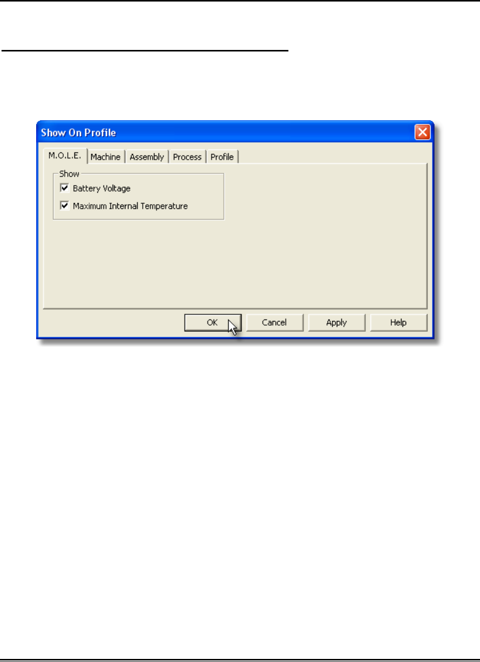
5.5.5.5. Show on Profile
M.O.L.E. status information can be displayed or hidden on the Data Graph.
To show machine information on the Data Graph:
1) On the M.O.L.E. menu, click Show on Profile.
2) Select or clear the associated machine characteristics to display or hide on the
Data Graph.
3) Click the OK command button to accept, or Cancel to quit the command.
MEGAM.O.L.E.® Help System Guide ♦290♦
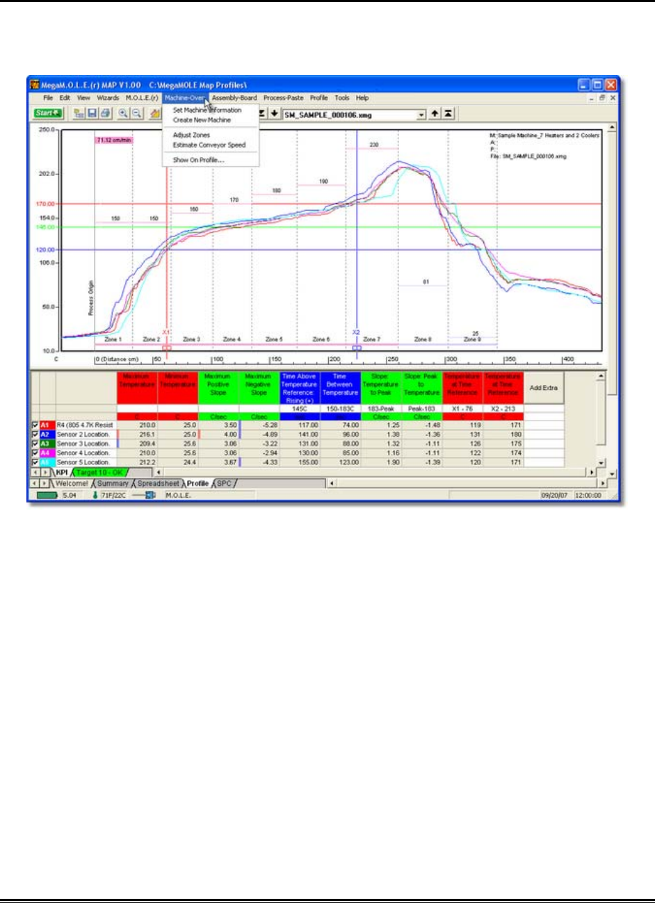
5.5.6. Machine-Oven Menu
The Machine-Oven menu include options to design specific machine models. Creating
an machine model allows the user to visualize it on the Data Graph along with the
associated data run profile.
♦291♦ MEGAM.O.L.E.® Help System Guide
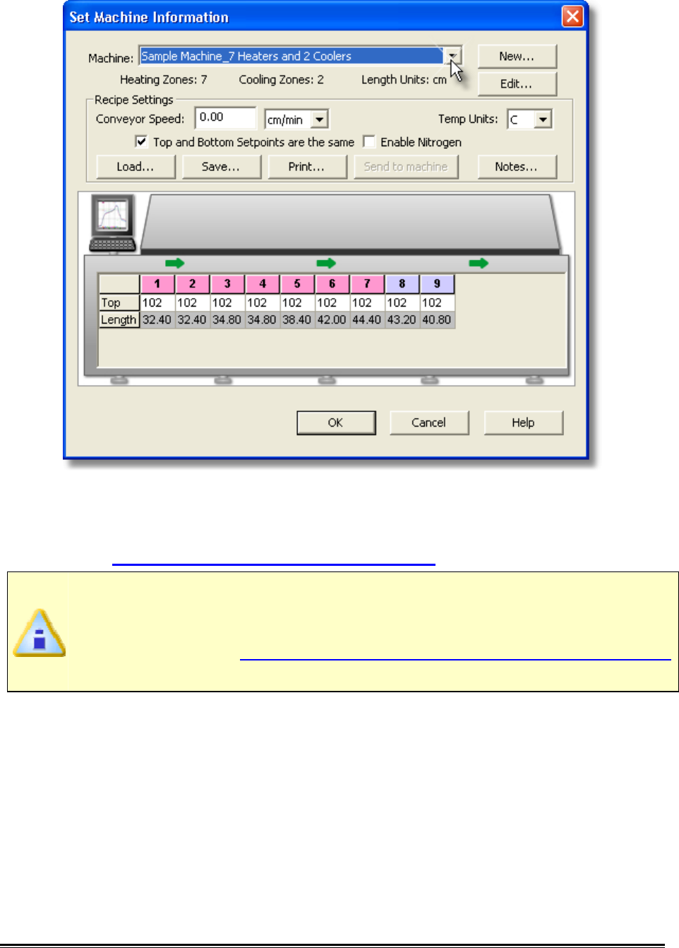
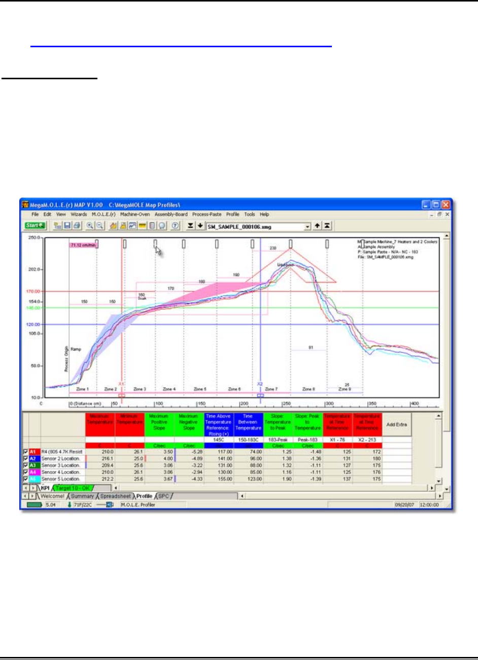
5.5.6.1. Set Machine Information
This command allows the user to set machine information and display it on the Data
Graph so the user can visually see how the data run profile lines up with the machine.
When setting machine information, this data will be applied to the currently
selected data run only. Existing defined machine models may not accurately
reflect your machine and are used as a starting template.
To set machine information:
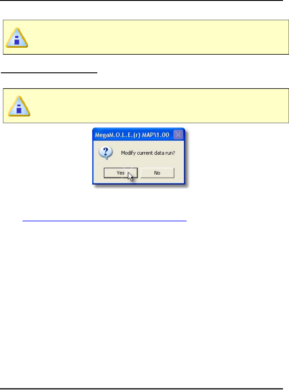
1) On the Machine-Oven menu, click Set Machine Information.
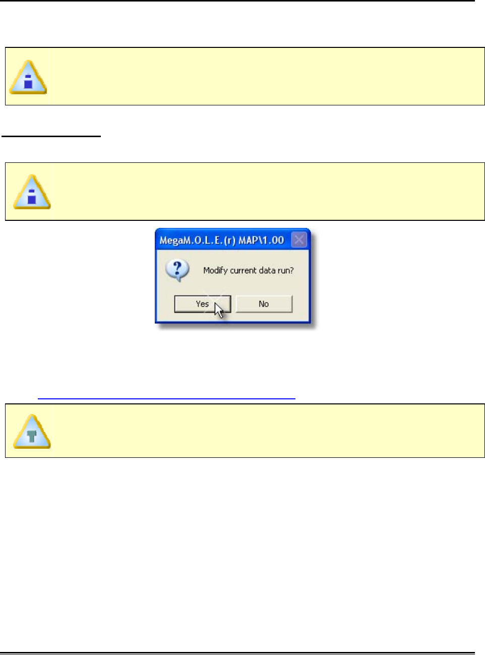
If a setting is already selected for a data run, the software will prompt the user
to decide if they wish to modify the current data run. Click the Yes command
button to continue or No to quit the command.
2) Select your machine from the Machine drop down list. If it does not appear in the
list click the New command button to create a new one. Refer to topic
Software>Menus>Machine>Create new Machine for more information.
MEGAM.O.L.E.® Help System Guide ♦292♦
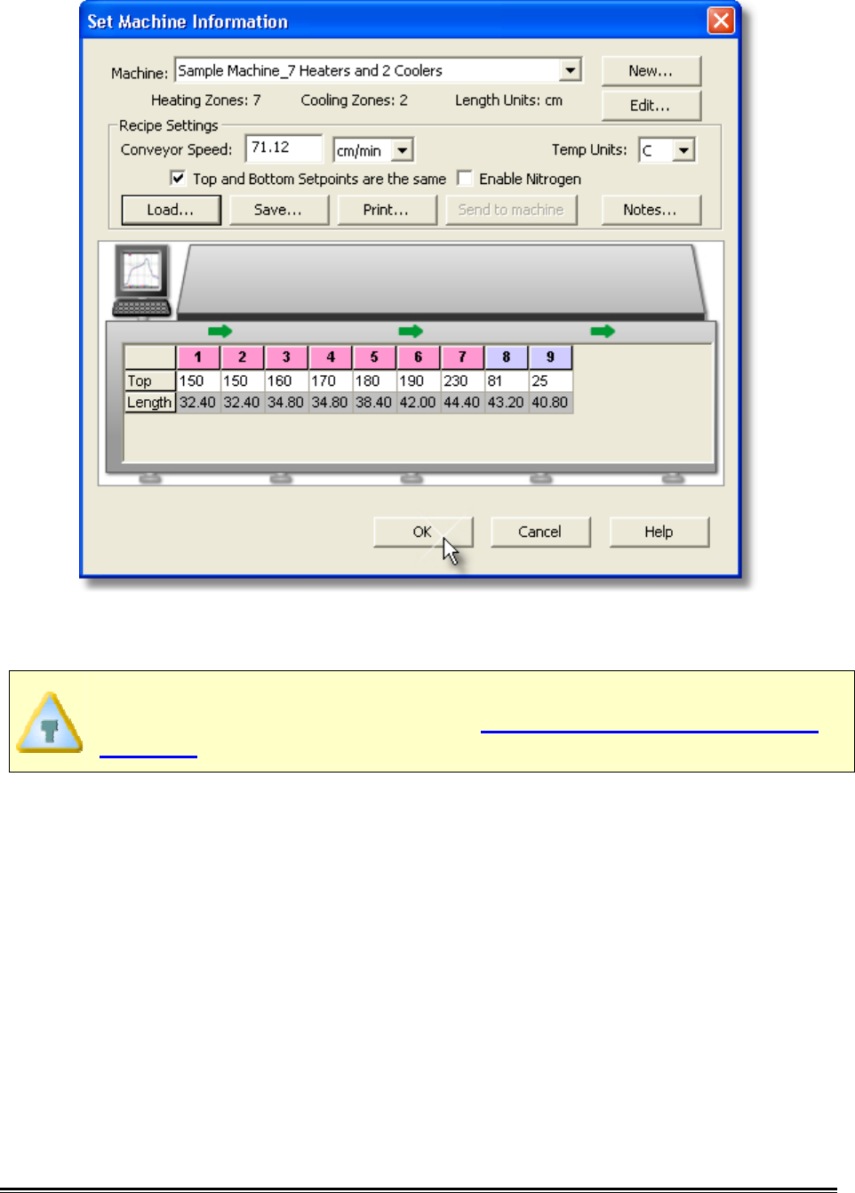
3) Set the machine conveyor speed. The software uses this value to calculate the
Time (X) Scale values when Distance units are displayed. This number is also
used as the actual conveyor speed when prediction data lines are added. Refer
to topic Software>Menus>Tools>Prediction Tool for more information.
To properly display a machine model on the Data Graph, a conveyor speed
must be set. If you do not know what the conveyor speed is, the software
allows you to estimate it based on the machine information and the data run
profile. Refer to topic Software>Menus>Machine>Estimate Conveyor Speed
for more information.
4) Set the machine temperature units.
5) Set the Zone Temperatures in the zone matrix. These temperatures could be the
upper and lower thresholds of acceptable temperatures to meet process
standards or temperature settings of upper and lower heat sources. Upper zone
temperatures appear as solid lines and lower zones appear as dotted lines on
the Data Graph.
♦293♦ MEGAM.O.L.E.® Help System Guide
6) Click the OK command button to set the machine information, or Cancel to quit
the command.
To view the machine information on the Data Graph, the Show on Profile
settings must be enabled. Refer to topic Software>Menus>Machine>Show
on Profile for more information.
MEGAM.O.L.E.® Help System Guide ♦294♦
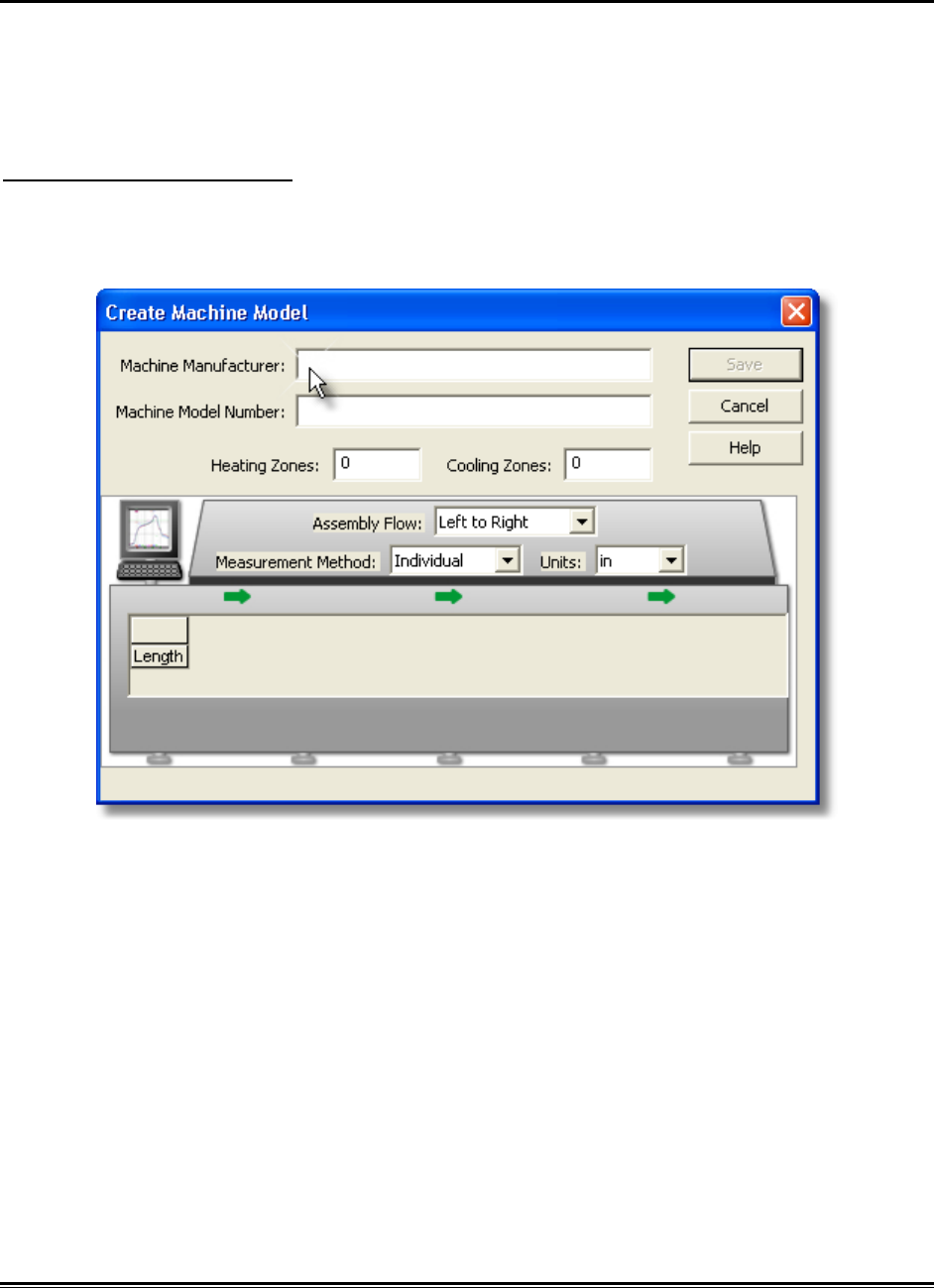
5.5.6.2. Create New Machine
When setting machine information, the user is required to select a machine. The
software includes basic machine models for the user to select from. If your machine
model does not appear in the list the software has the ability for you to create a new
machine model.
To create a new machine:
1) On the Machine-Oven menu, click Create New Machine.
2) Enter the machine manufacturer and model number.
3) Enter the amount of heating and cooling zones. As zones are specified the zone
matrix will automatically grow to allow you to enter zone measurements.
♦295♦ MEGAM.O.L.E.® Help System Guide
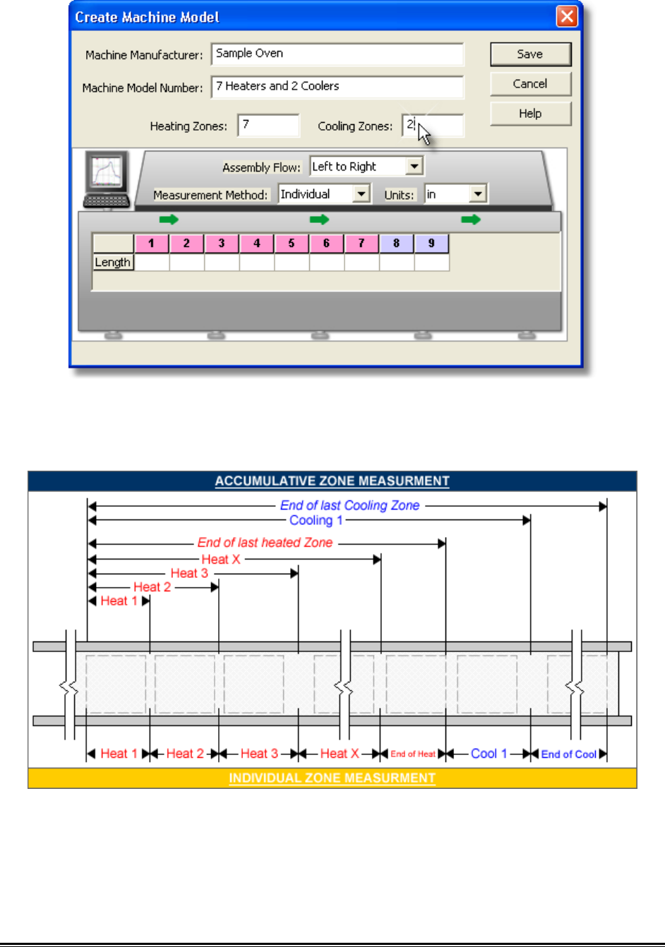
4) Select the assembly flow (left to right or right to left), zone measurement method
(individual or accumulative) and units of measurement. Refer to the illustration
below for proper measurement methods.
5) Enter the zone measurements in the zone matrix.
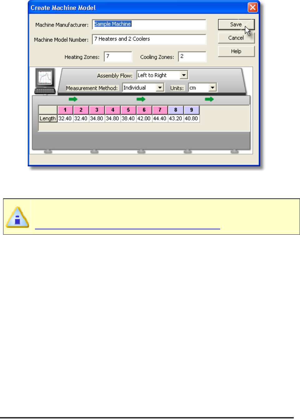
MEGAM.O.L.E.® Help System Guide ♦296♦
6-) Click the Save command button to save the new machine, or Cancel to quit the
command.
The new machine will now appear in the Machine drop-down list on the Set
Machine Information dialog box. Refer to topic
Software>Menus>Machine>Set Machine Information for more information.
♦297♦ MEGAM.O.L.E.® Help System Guide
5.5.6.3. Adjust Zones
This command allows the user to manually adjust the displayed machine zones on the
Data Graph. To use this command a machine must be selected and displayed. Refer to
topic Software>Menus>Machine>Set Machine Information.
To adjust zones:
1) One the Machine-Oven menu, click Adjust Zones to activate. A check mark
appears to the left of the command indicating the software is in Adjust Zones
mode.
2) Position the mouse pointer over a desired machine zone line.
3) Click and hold the left mouse button to drag it left or right releasing the mouse
button when the machine zone line is at the desired location.
4) Lock the settings by selecting the Adjust Zones command again. This removes
the check mark next to the command indicating the software is not in Adjust
Zones mode.
MEGAM.O.L.E.® Help System Guide ♦298♦
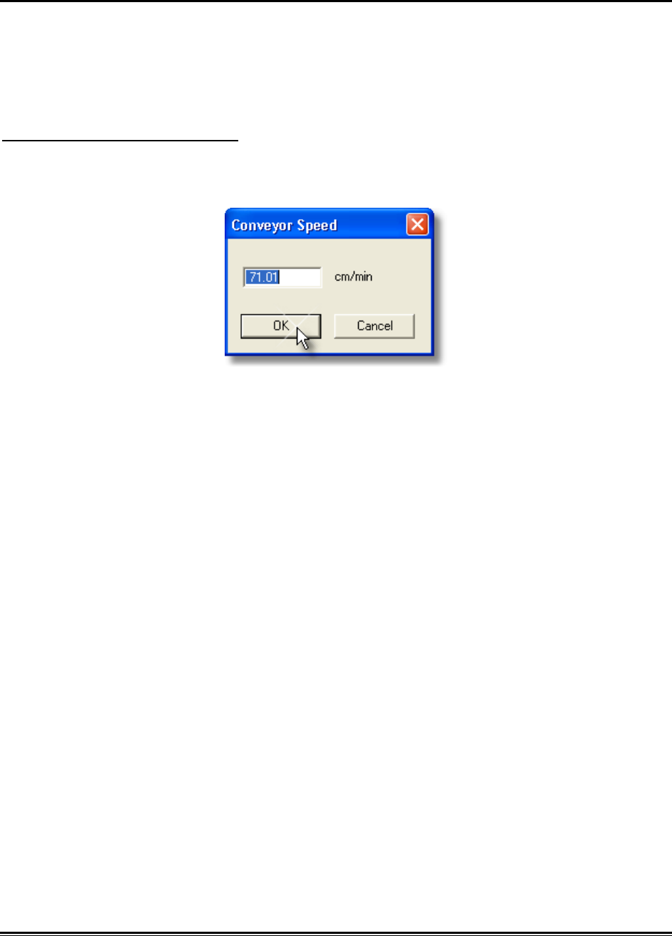
5.5.6.4. Estimate Conveyor Speed
To properly display a machine model on the Data Graph, a conveyor speed must be
set. If you do not know what the conveyor speed is when setting machine information,
the software allows you to estimate it based on the machine information and the data
run profile.
To estimate conveyor speed:
1) On the Machine-Oven menu, click Estimate Conveyor Speed. and the
estimated conveyor speed automatically is displayed in the text box.
2) Click the OK command button to accept the estimated conveyor speed, or
Cancel to quit the command.
♦299♦ MEGAM.O.L.E.® Help System Guide
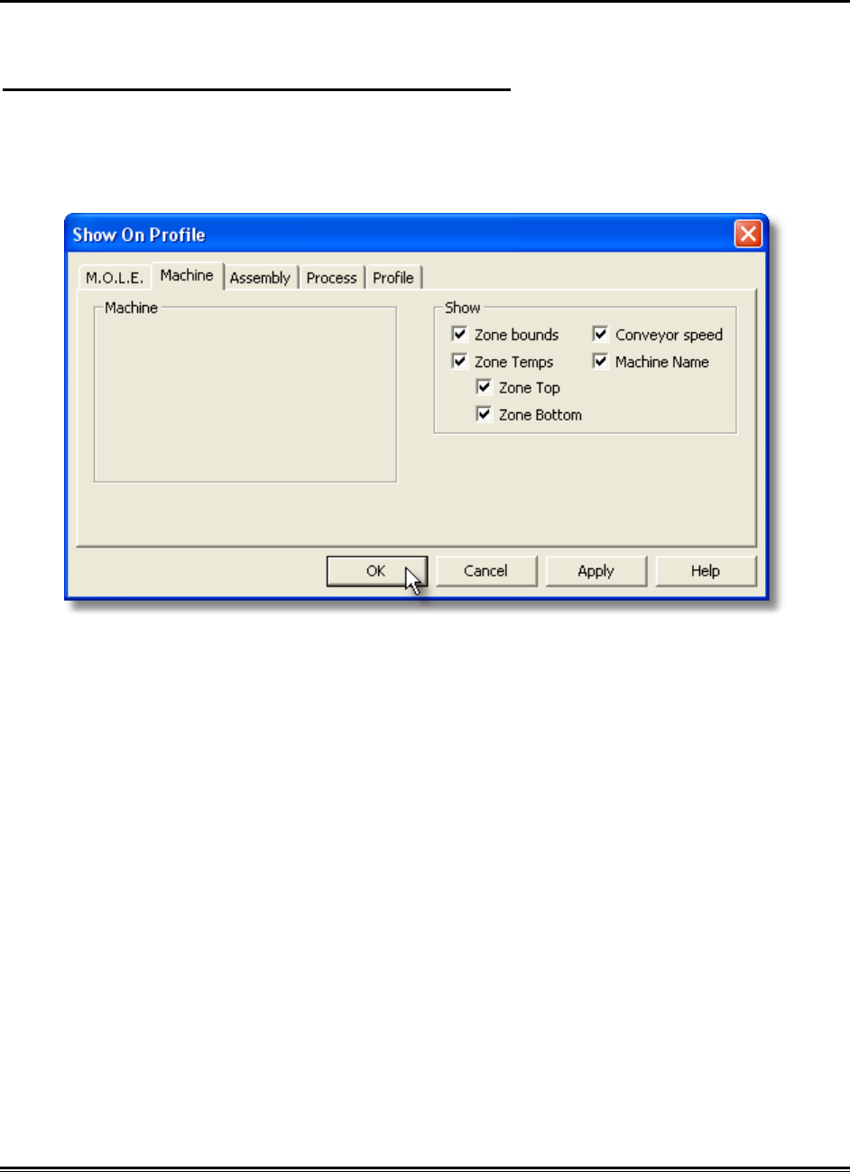
5.5.6.5. Show on Profile
Machine information can be displayed or hidden on the Data Graph.
To show machine information on the Data Graph:
1) On the Machine-Oven menu, click Show on Profile.
2) Select or clear the associated machine characteristics to display or hide on the
Data Graph.
3) Click the OK command button to accept, or Cancel to quit the command.
MEGAM.O.L.E.® Help System Guide ♦300♦
5.5.7. Assembly-Board Menu
The Assembly-Board menu includes commands that enable the user to set and edit
experimental assembly documentation.
♦301♦ MEGAM.O.L.E.® Help System Guide
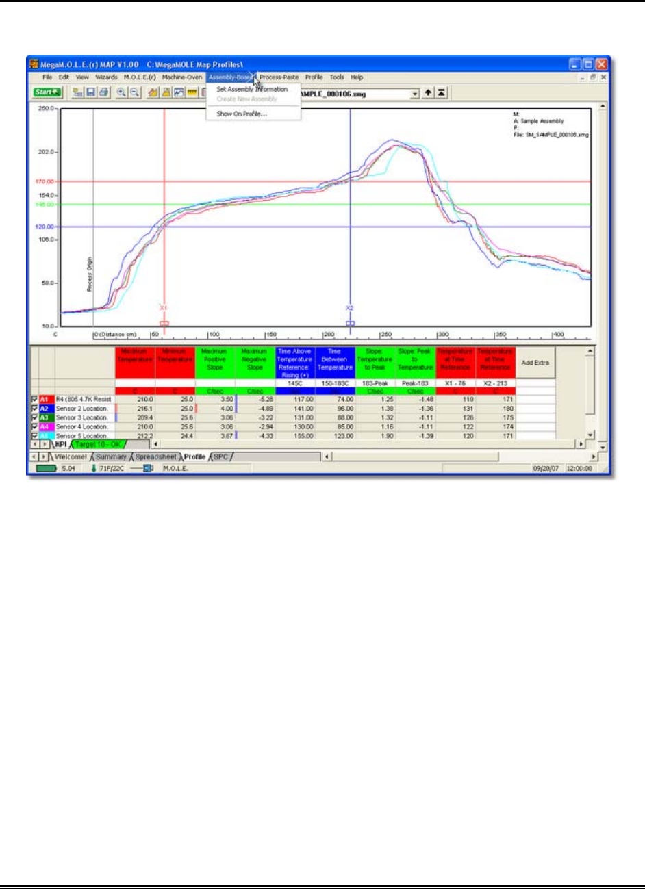
5.5.7.1. Set Assembly Information
This command allows the user to set assembly information associated with the selected
data run profile.
When setting assembly information, this data will be applied to the currently
selected data run only.
To enter sensor information:
1) On the Assembly-Board menu, click Set Assembly Information.
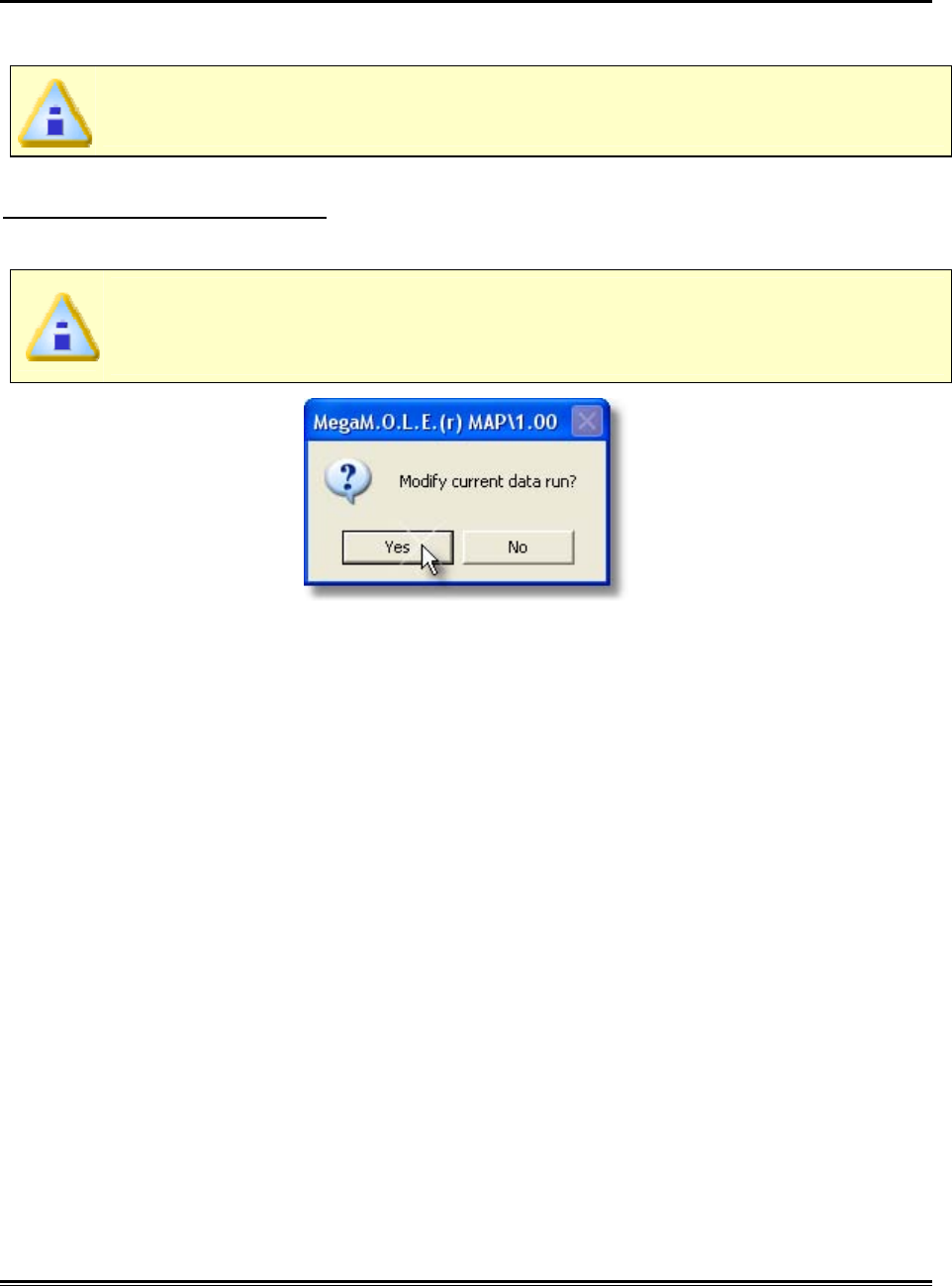
If a setting is already selected for a data run, the software will prompt the user
to decide if they wish to modify the current data run. Click the Yes command
button to continue or No to quit the command.
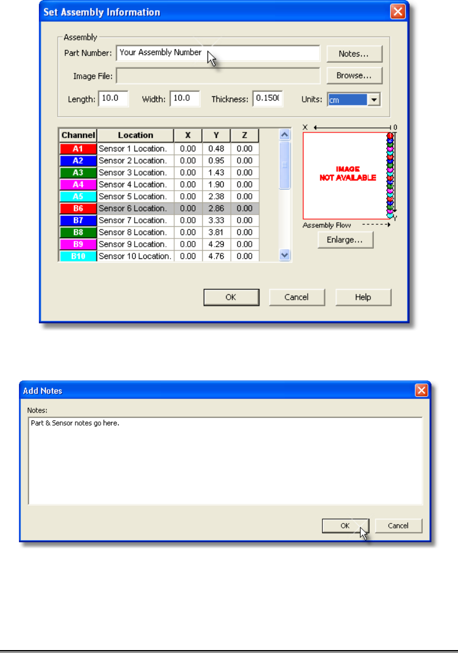
2) Enter an assembly part number.
MEGAM.O.L.E.® Help System Guide ♦302♦
3) Click the Notes command button if you would like to enter part documentation
about the test assembly being profiled.
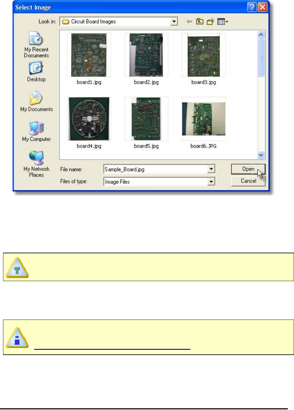
4) Click the image file Browse command button to select a product image. Image
files supported by the software are Dib-(.dib), Gif (.gif), Pcx (.pcx), Tiff (.tif), Targa
(.tga), Bitmap (.bmp) and Jpeg (.jpg).
♦303♦ MEGAM.O.L.E.® Help System Guide
5) Enter the test assembly board length, width and thickness.
6) Enter the sensor location descriptions. These descriptions can be the location
where each sensor is connected to the test product. The channel color
associated with the description indicates which Data Plot on the Data Graph it
represents.
Thermocouple placement information entered in the sensor location matrix are
also displayed as the Sensor Locations in the Data Table.
7) Enter sensor location dimensions. Sensor Locations can also be set by dragging
sensor location markers on the selected image. To move the markers, click the
Enlarge command button below the assembly image and the Set Sensor
Locations dialog box appears.
Specified X-dimensions may be altered when using the Align Profile Peaks
command to align the data run profile lines. Refer to topic
Software>Menus>Profile>Align Profile Peaks for more information.
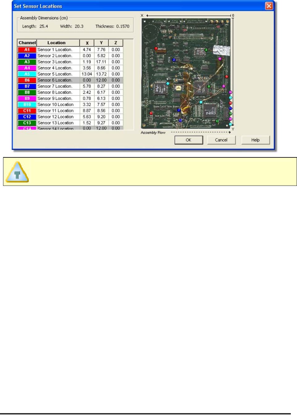
MEGAM.O.L.E.® Help System Guide ♦304♦
X-dimensions are measured from the leading (right) edge or the first edge to
enter the process, and Y dimensions are from the top down.
8) Select which sensor channels to display in the Data Table. Excluding a sensor
channel does not delete channel data and can be turned back on at any time.
This is helpful when data has been collected and it may not be beneficial to the
data run profile.
♦305♦ MEGAM.O.L.E.® Help System Guide
9) Click the OK command button accept or Cancel to quit the command.
MEGAM.O.L.E.® Help System Guide ♦306♦
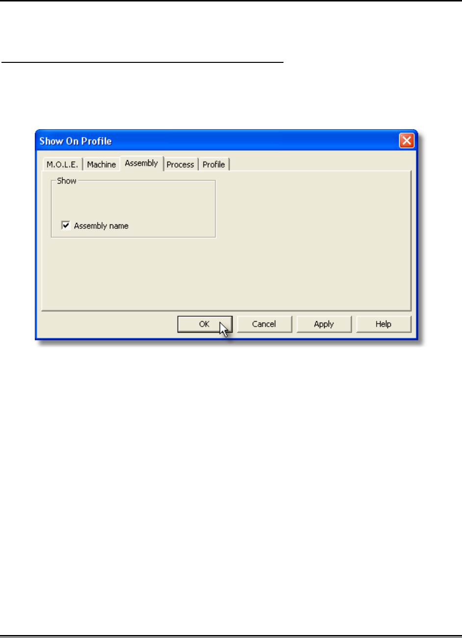
5.5.7.2. Show on Profile
Assembly name can be displayed or hidden on the MAP data section of the Data
Graph.
To show assembly information on the Data Graph:
1) On the Assembly-Board menu, click Show on Profile.
2) Select or clear the Assembly name check box to display or hide it on the Data
Graph.
3) Click the OK command button to accept, or Cancel to quit the command.
♦307♦ MEGAM.O.L.E.® Help System Guide
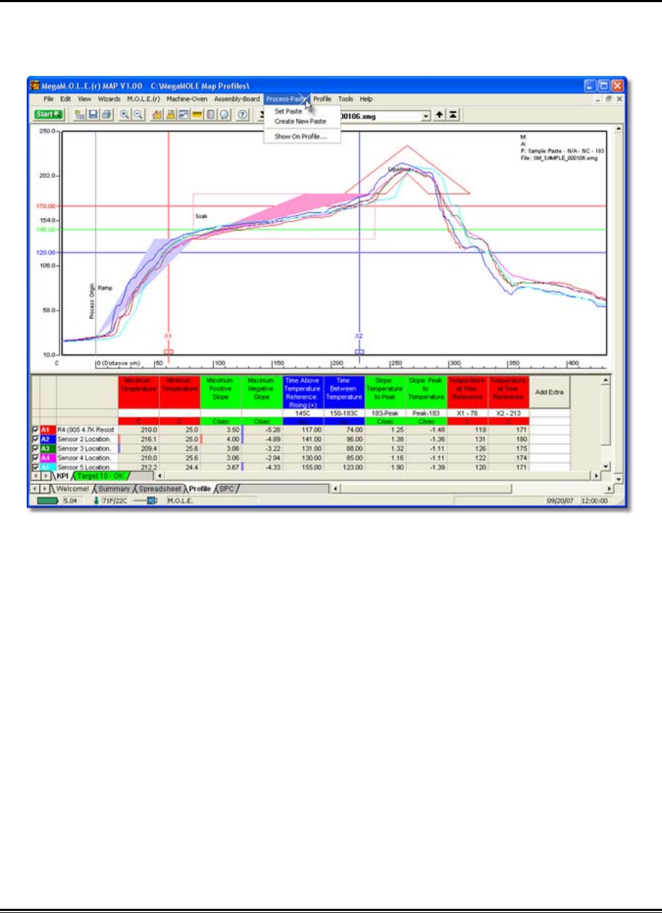
5.5.8. Process-Paste Menu
The Process-Paste menu include options to select or design a process paste. Creating
an process paste allows the user to visualize it on the Data Graph along with the
associated data run profile.
MEGAM.O.L.E.® Help System Guide ♦308♦
5.5.8.1. Set Process
This command allows the user to set a process paste and display it on the Data Graph
so the user can visually see how the data run profile lines up with the process
specification.
When setting a process, this data will be applied to the currently selected data
run only. Existing defined machine models may not accurately reflect your
machine and are used as a starting template.
To set a process:
1) On the Process-Paste menu, click Set Process.
If a setting is already selected for a data run, the software will prompt the user
to decide if they wish to modify the current data run. Click the Yes command
button to continue or No to quit the command.
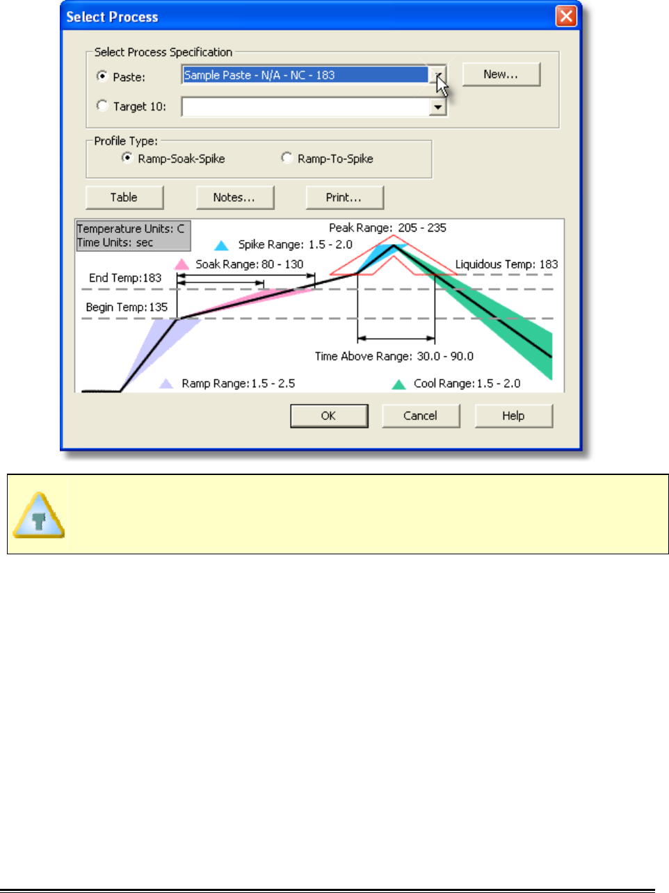
2) Select your process specification. The user can select a Paste from the database
or a pre-defined Target 10 file. If the desired paste does not appear in the
database list click the New command button to create a new one. Refer to topic
Software>Menus>Process>Create new Paste for more information.
When a paste specification is selected, the software automatically creates a
Target 10 specification file for future use.
♦309♦ MEGAM.O.L.E.® Help System Guide
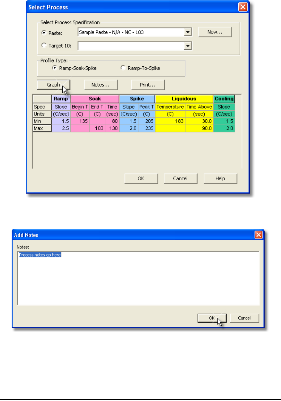
3) Choose the Profile Type (Ramp-Soak-Spike or Ramp-to-Spike).
Once a process is selected, the specifications are displayed on the graph. The
software also allows paste specification data to be viewed in a table view by
clicking the Table command button.
MEGAM.O.L.E.® Help System Guide ♦310♦
4) Click the Notes command button if you would like to enter process paste
documentation.
5) Click the OK command button to set the process, or Cancel to quit the
command.

♦311♦ MEGAM.O.L.E.® Help System Guide
To view the process on the Data Graph, the Show on Profile settings must be
enabled. Refer to topic Software>Menus>Process>Show on Profile for more
information.
MEGAM.O.L.E.® Help System Guide ♦312♦
5.5.8.2. Create New Paste
When setting machine information, the user is required to select a machine. The
software includes basic machine models for the user to select from. If your machine
model does not appear in the list the software has the ability for you to create a new
machine model.
To create a new paste:
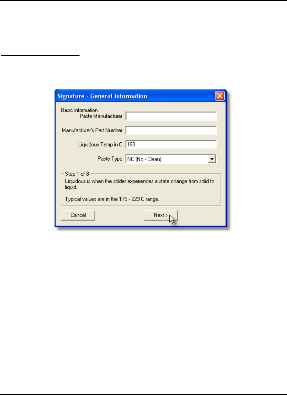
1) On the Process-Paste menu, click Create New Paste.
2) Enter the required information and select the Next button.
3) Enter the RAMP – Slope information and select the Next button.
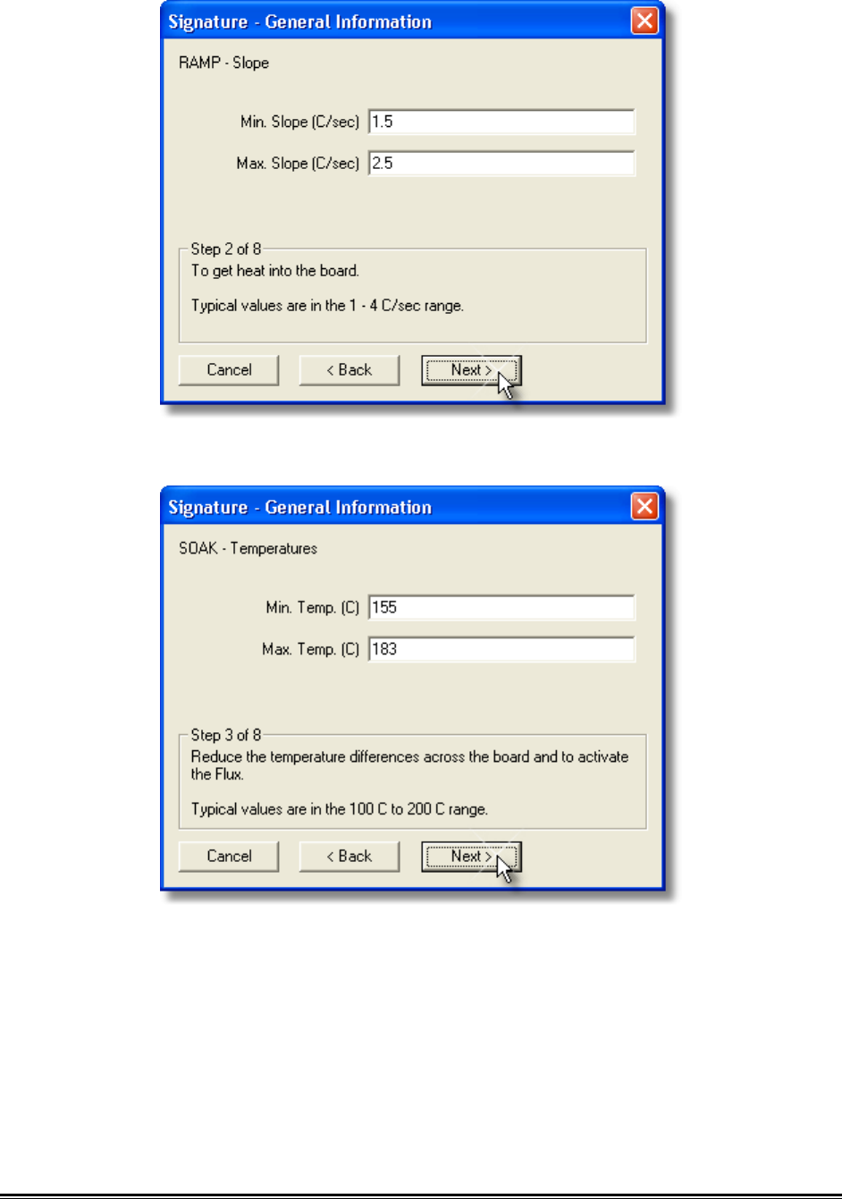
♦313♦ MEGAM.O.L.E.® Help System Guide
4) Enter the SOAK –Temperatures information and select the Next button.
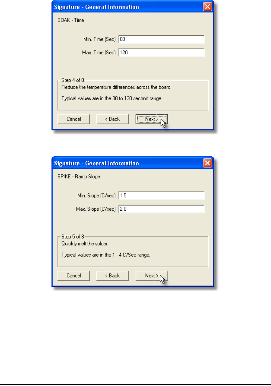
5) Enter the SOAK –Time information and select the Next button.
MEGAM.O.L.E.® Help System Guide ♦314♦
6) Enter the SPIKE – Ramp Slope information and select the Next button.
7) Enter the SPIKE – Time Above information and select the Next button.
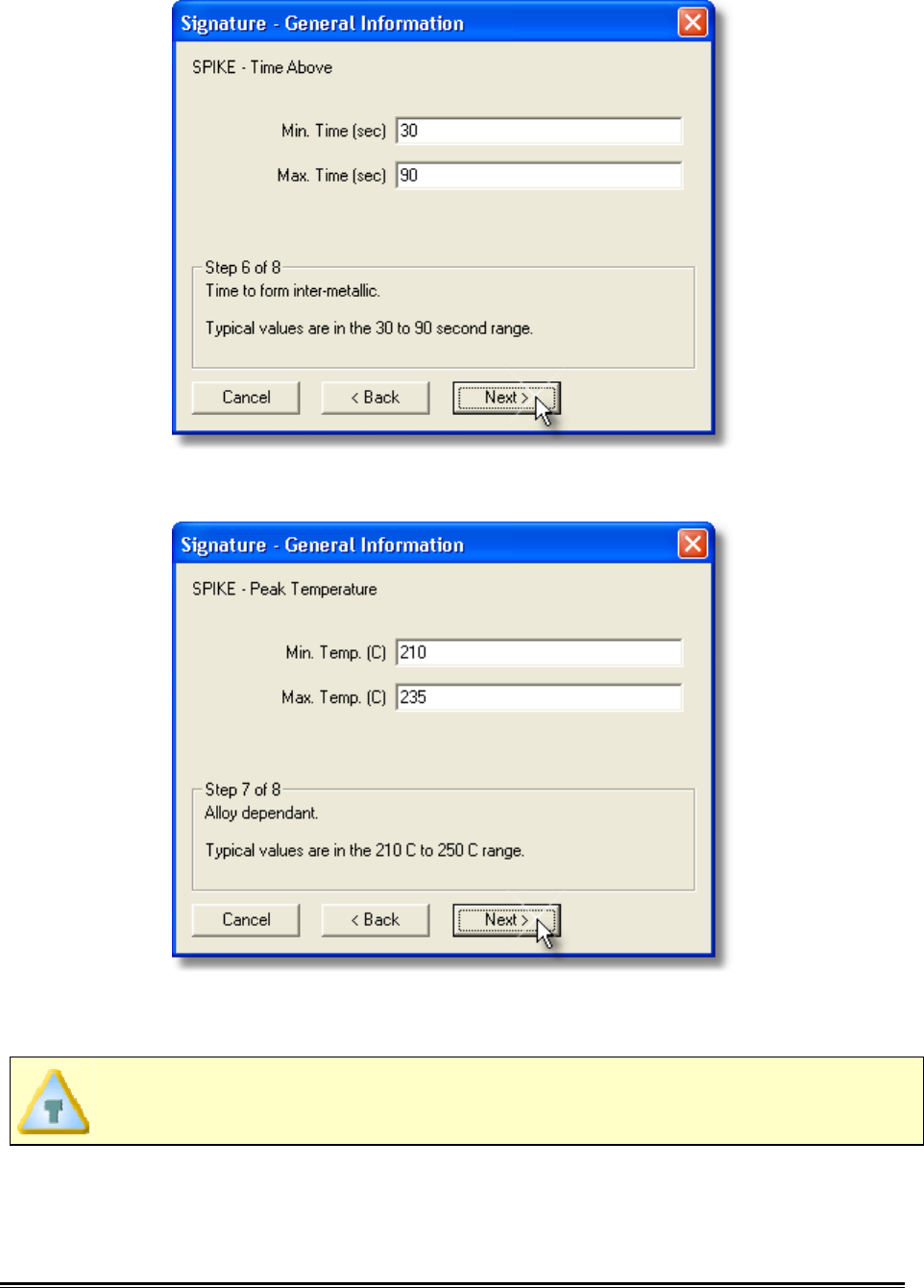
♦315♦ MEGAM.O.L.E.® Help System Guide
8) Enter the SPIKE – Peak Temperature information and select the Next button.
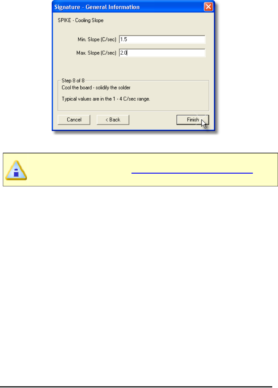
9) Enter the SPIKE – Cooling Slope information and select the Finish button to
create the new paste and return to the Paste Specification database dialog box.
Once the user proceeds to each Step, the Back button can be selected to
confirm or modify previously entered information.
MEGAM.O.L.E.® Help System Guide ♦316♦
10) Click the Finish command button to accept, or Cancel to quit the command.
The new process paste will now appear in the Paste drop-down list on the Set
Paste dialog box. Refer to topic Software>Menus>Process>Set Paste for
more information.
♦317♦ MEGAM.O.L.E.® Help System Guide
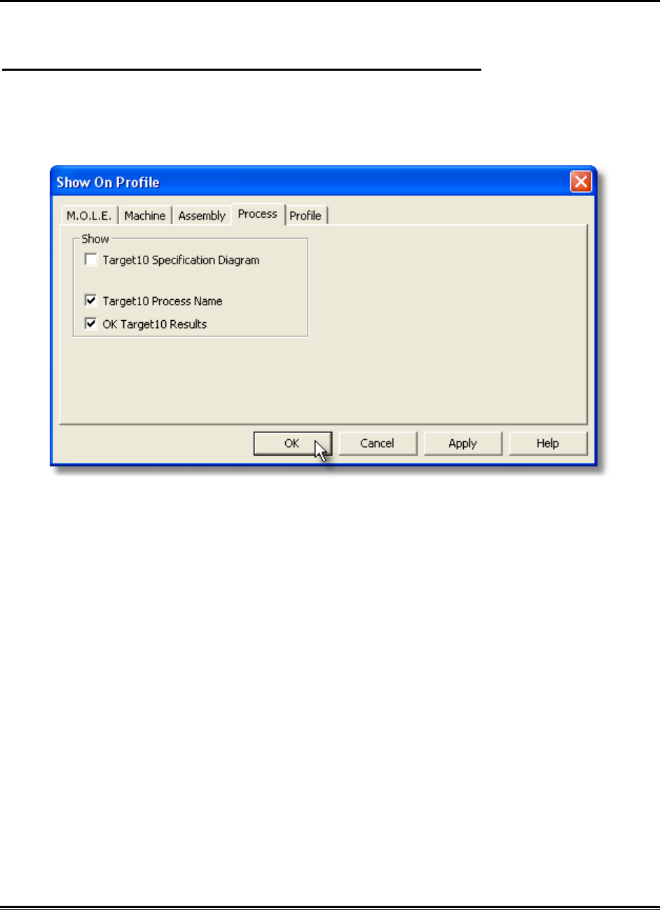
5.5.8.3. Show on Profile
Process Paste specification can be displayed or hidden on the Data Graph.
To show the process paste specification on the Data Graph:
1) On the Process-Paste menu, click Show on Profile.
2) Select or clear the associated process paste options to display or hide on the
Data Graph.
3) Click the OK command button to accept, or Cancel to quit the command.

MEGAM.O.L.E.® Help System Guide ♦318♦
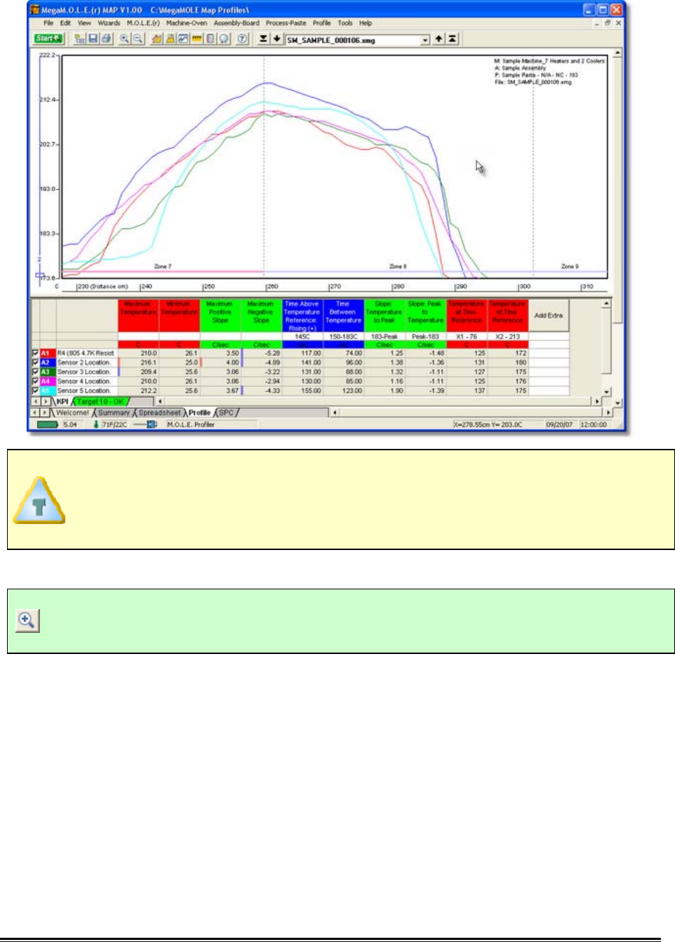
5.5.9. Profile Menu
The Profile menu includes special commands specifically used on the Profile worksheet.
Commands in this menu enable the user to view and edit data run documentation,
change the appearance of the Data Graph and design experiments.
♦319♦ MEGAM.O.L.E.® Help System Guide
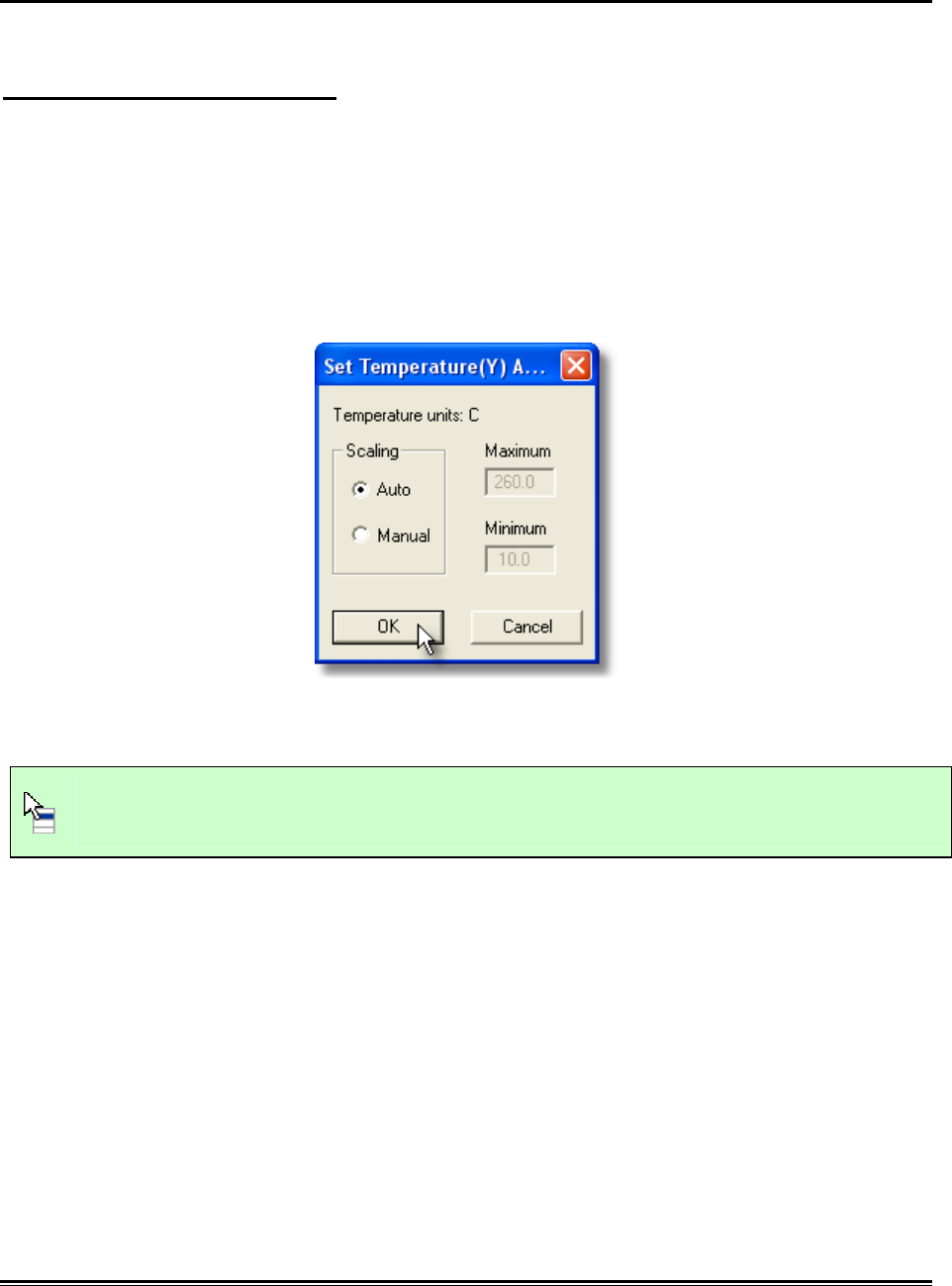
5.5.9.1. Set Temperature (Y) Scale
This command controls the scale of the Temperature (Y) axis on the Data Graph.
To use the scaling command:
1) On the Profile menu, click Set Temperature (Y) Scale. This dialog box identifies
the current settings of the displayed units and the maximum and minimum
values.
2) Select between Auto or Manual mode. In Auto mode, the software selects the
scale of the Y-Axis to ensure all Data Point values and the highest Zone
temperature settings are visible in the Data Graph. In Manual mode, the range of
values must be manually set.
3) Click the OK command button to use the settings or Cancel to quit the
command.
This command can also be accessed by double-clicking the scale on the Data
Graph.
MEGAM.O.L.E.® Help System Guide ♦320♦
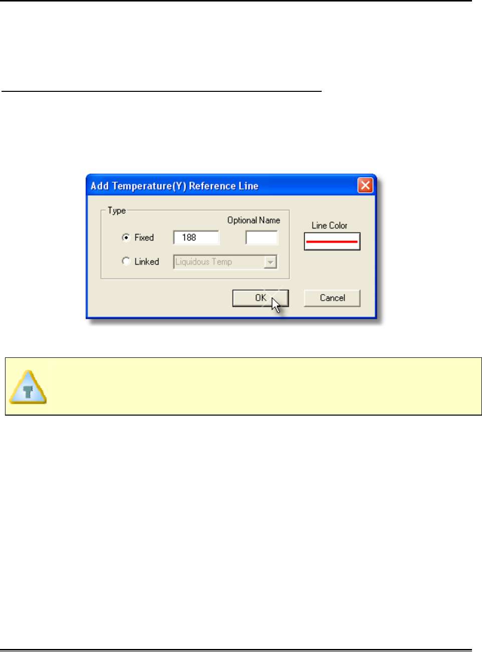
5.5.9.2. Add Temperature (Y) Reference Lines
Temperature Reference Lines are colored horizontal lines and can be positioned
anywhere within the range of Y-values in the graph.
They are used for analysis when the Temperature (Y) parameter calculations are
displayed in the Data Table.
To add Temperature Reference Lines to the Data Graph:
1) On the Profile menu, click Add Temperature (Y) Reference Line.
2) Choose the reference line Type (Fixed and Linked). If Fixed is selected, enter a
fixed Temperature value. If Linked is selected, select a portion of the profile to
link it to.
3) Select the line color by clicking the line button below the label.
When an reference line is displayed on the Data Graph, the default label is the
specified temperature. The software allows the user to rename the line by
using the Optional Name text box.
♦321♦ MEGAM.O.L.E.® Help System Guide
4) Click the OK command to accept the new settings or Cancel to quit the
command.
This command can also be accessed by right-clicking the scale on the Data
Graph and select Add Temperature (Y) Scale from the shortcut menu.
To move an Temperature (Y) Reference Line:
1) Position the mouse pointer over the desired reference line.
2) Double-click the reference line and the Add Temperature (Y) Reference line
dialog box appears.
3) Edit the reference line settings and click the OK command to accept the new
settings or Cancel to quit the command.
MEGAM.O.L.E.® Help System Guide ♦322♦
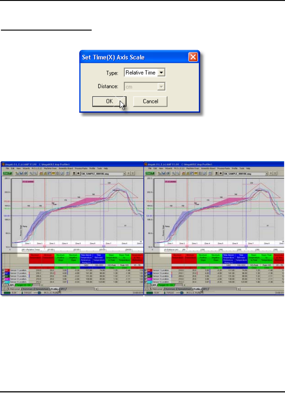
5.5.9.3. Set Time (X) Scale
This command controls the scale of the Time (X) axis on the Data Graph.
To select a Time (X) scale:
1) On the Profile menu, click Set Time (X) Scale.
2) Select the scale Type and Distance units.
3) Click the OK command button to accept the changes, or Cancel to discard any
changes.
Relative Time Scale Distance Scale
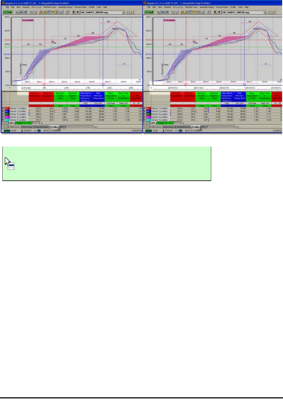
♦323♦ MEGAM.O.L.E.® Help System Guide
Points Scale Absolute Time Scale
This command can also be accessed by right-clicking the
scale on the Data Graph and select Set Time (X) Scale
from the shortcut menu.
MEGAM.O.L.E.® Help System Guide ♦324♦
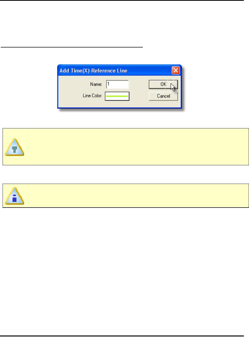
5.5.9.4. Add Time (X) Reference Lines
Time Reference Lines are colored vertical lines that can be positioned anywhere within
the range of X-values on the Data Graph.
These reference lines indicate the temperature values at the intersection of a Data Plot
with each displayed reference line.
To add Time Reference Lines to the Data Graph:
1) On the Profile menu, click Add Time (X) Reference Line.
2) Select the line color by clicking the line button below the label.
When a reference line is displayed on the Data Graph, the default label is the
next number of reference line. For example if there is two reference lines
displayed, the next default label will be 3. The software allows the user to
rename the line by using the Name text box.
3) Click the OK command to accept the new settings or Cancel to quit the
command.
If a reference line is used in a Data Table calculation, the name of the
reference appears in the header along with the parameter value.
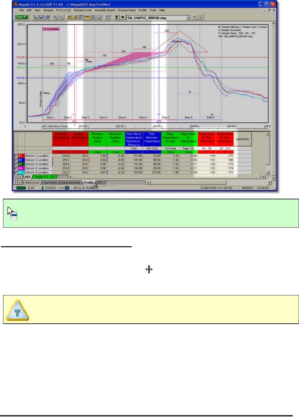
♦325♦ MEGAM.O.L.E.® Help System Guide
This command can also be accessed by right-clicking the scale on the Data
Graph and select Add Time (X) Reference from the shortcut menu.
To move an Time (X) Reference Line:
1) Position the mouse pointer over the a Time (X) Reference line.
2) When the mouse pointer becomes a , click and hold the left mouse button to
drag it left or right releasing the mouse button when the Time (X) Reference line
is at the desired location.
When moving the selected Time (X) Reference line, it can be moved past other
cursors to any location on the Data Graph.
When a Time (X) Reference line is moved to a new position, it snaps to the closest real
Time (X) value. Notice on highly magnified graphs that the line jumps from point to
point. The values in the Data Table are automatically updated to reflect the new
position.

MEGAM.O.L.E.® Help System Guide ♦326♦
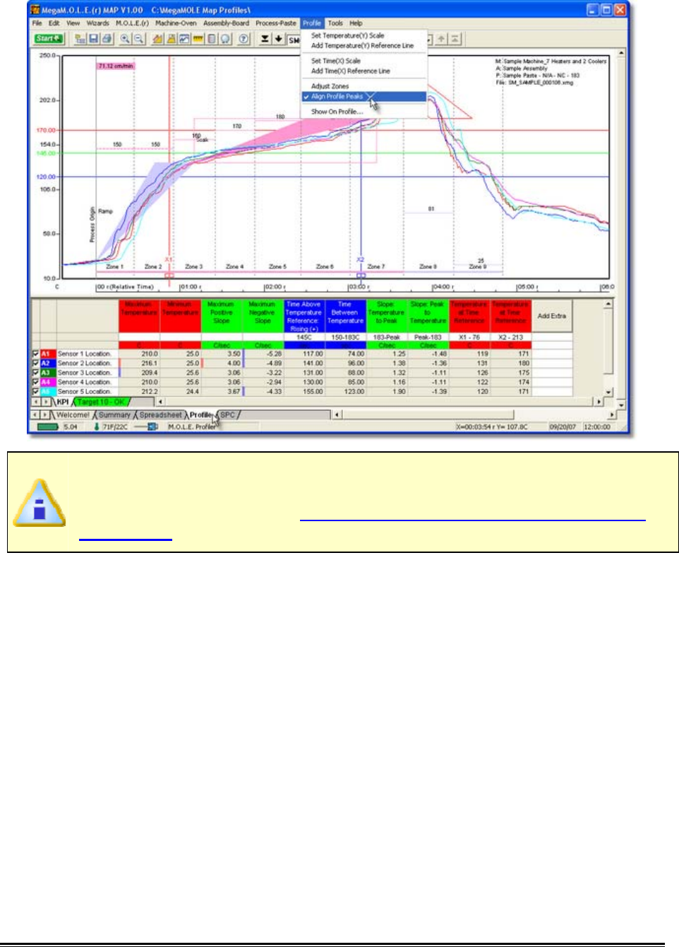
5.5.9.5. Align Profile Peaks
If sensors are placed along a line parallel to the direction of flow in a conveyorized
process so they enter and exit oven zones at different times, the resulting Data Plots lag
behind one another. The Align Profile Peaks command automatically aligns the Time
(X) axis maximum peak values for each Data Plot so the results can be easily compared
during analysis.
A conveyor speed must be set to properly use this command. Refer to topic
Software>Menus>Machine>Set Machine Information or Software>Page
Tabs>Profile>Data Graph>Conveyor Speed Indicator for more details.
To align profile peaks:
1) On the Profile menu, click Align Profile Peaks the channel lag values are
automatically calculated, and the Data Plots adjust to reflect them. A check mark
appears to the left of the command indicating the software is in Align Profile
Peaks mode. Repeat this step to disable the command.
♦327♦ MEGAM.O.L.E.® Help System Guide
If sensor X-dimension values were previously entered in the Set Assembly
Information dialog box, Align Profile Peaks will automatically overwrite the
current values. Refer to topic Software>Menus>Assembly>Set Assembly
Information for more information.
MEGAM.O.L.E.® Help System Guide ♦328♦
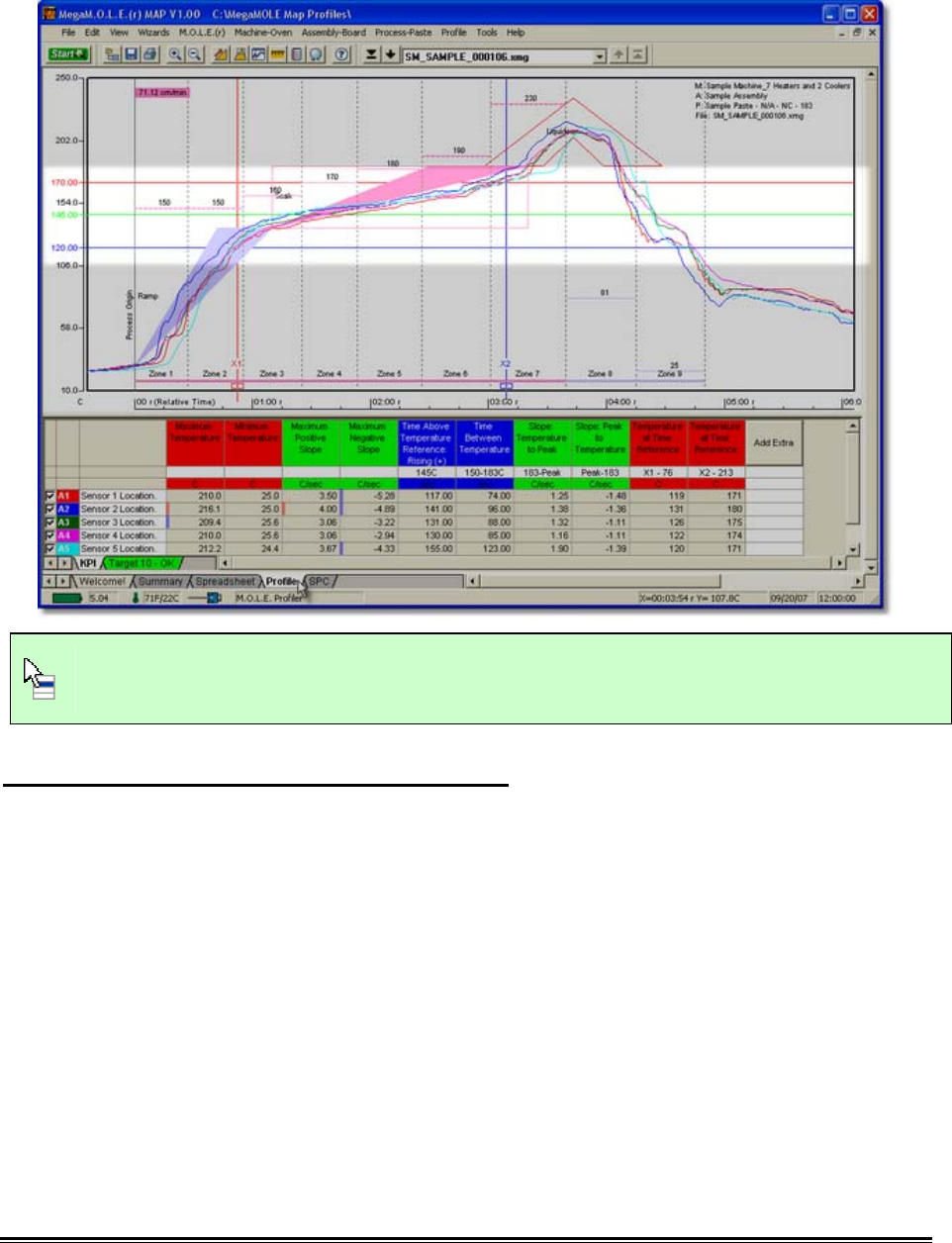
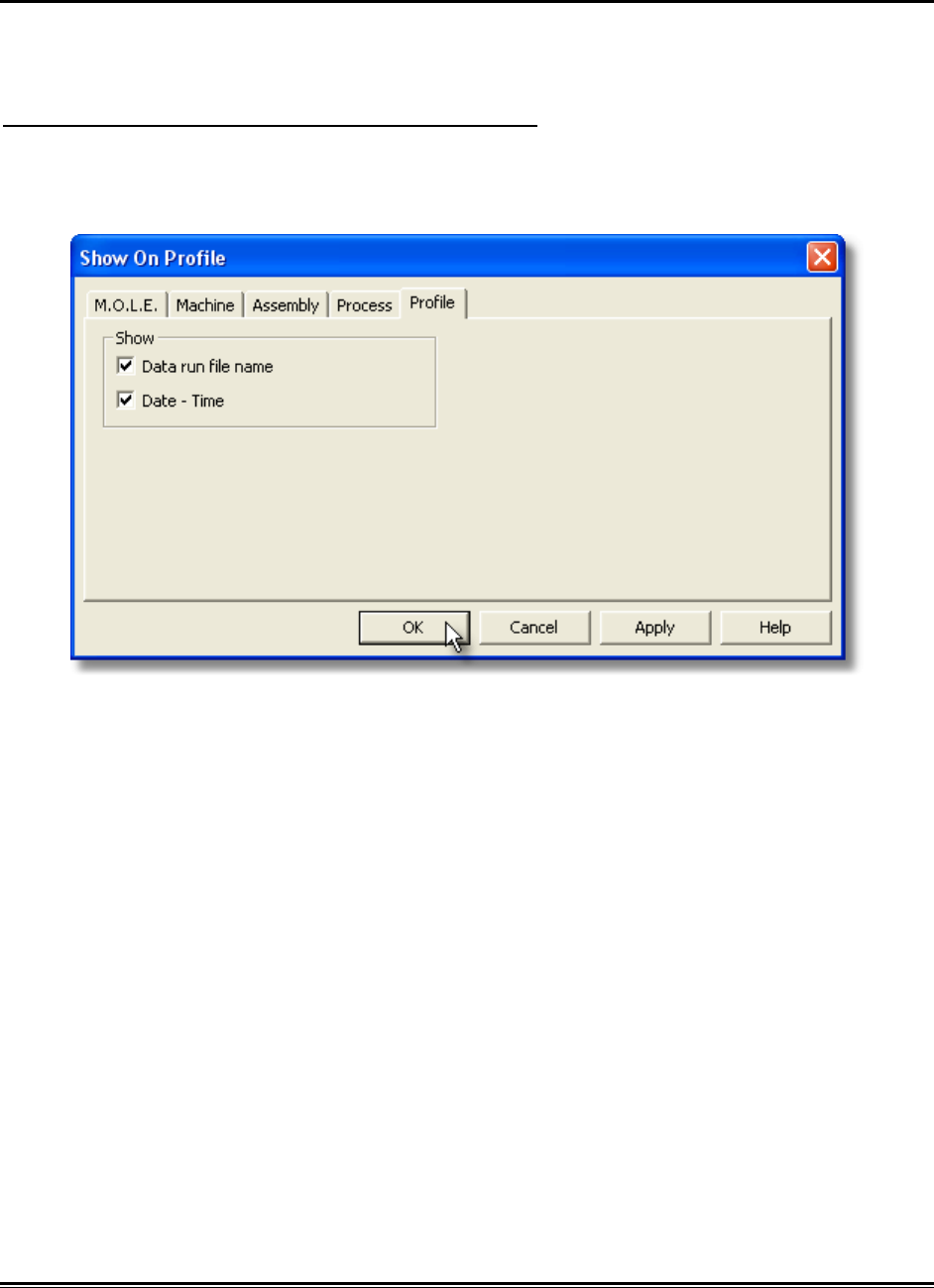
5.5.9.6. Show on Profile
The data run file name can be displayed or hidden on the MAP data section of the Data
Graph.
To show profile information on the Data Graph:
1) On the Profile menu, click Show on Profile.
2) Select or clear the File Name check box to display or hide it on the Data Graph.
3) Click the OK command button to accept, or Cancel to quit the command.
♦329♦ MEGAM.O.L.E.® Help System Guide
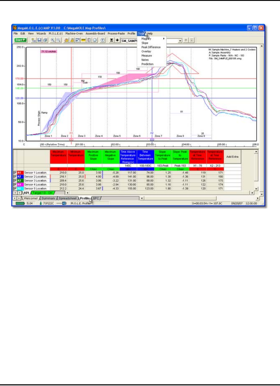
5.5.10. Tools Menu
Options in this menu help the user manipulate and analyze the data run profile
displayed on the Data Graph.
MEGAM.O.L.E.® Help System Guide ♦330♦
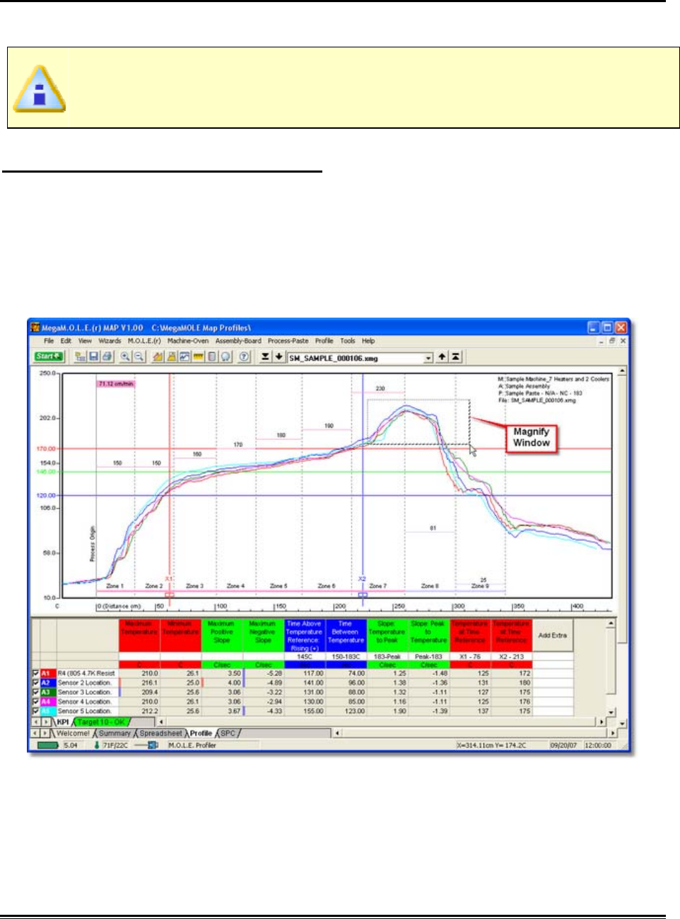
5.5.10.1. Magnify
The Magnify tool enlarges any selected area of the data graph for easy visual
examination.
When a Magnified Window constraint is applied to a parameter in the Data
Table, the Magnify tool is used to enlarge a portion of the Data Graph, and the
values within the magnified area are displayed in the Data Table.
To magnify a portion of the Data Graph:
1) On the Tools menu, point to Magnify then select Select Area.
2) Position the mouse pointer on a corner of the area to enlarge.
3) Press the left mouse button and drag the pointer diagonally to the opposite
corner to form a box around the area to be magnified. An outline of the box
appears as you drag.
4) Release the left mouse button when the outline of the area to be magnified is
visible. The area inside the box is then magnified to fill the entire Data Graph.
♦331♦ MEGAM.O.L.E.® Help System Guide
To show even more detail in the Data Graph, Magnify can be performed
multiple times. If the Magnify tool reaches the maximum zoom capability the
software will display a message box informing that the user has “Zoomed to
Tight”.
This command can be accessed on the Toolbar when the Profile Tab is active.
Magnify Button
MEGAM.O.L.E.® Help System Guide ♦332♦
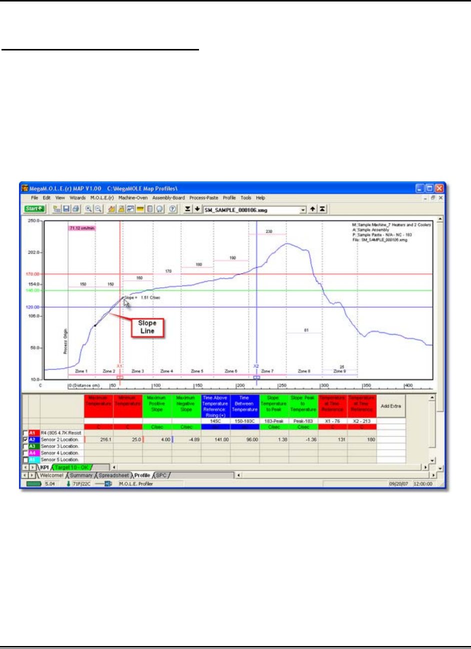
5.5.10.2. Slope
The Slope tool finds the average slope between any two points in the Data Graph.
To find the average slope of a line:
1) On the Tools menu, click Slope.
2) Position the mouse pointer at a point on the curve.
3) Press and hold the left mouse button.
4) Drag the pointer to the end of the desired slope line.
5) Release the left mouse button when the pointer is at the desired location. The
software will draw a slope line on the Data Graph, and label the slope value.
♦333♦ MEGAM.O.L.E.® Help System Guide
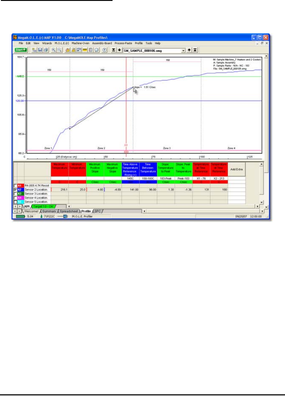
To obtain more accurate slopes:
1) On the Tools menu, click Magnify to magnify a portion of the Data Graph
2) Repeat the Slope command.
MEGAM.O.L.E.® Help System Guide ♦334♦
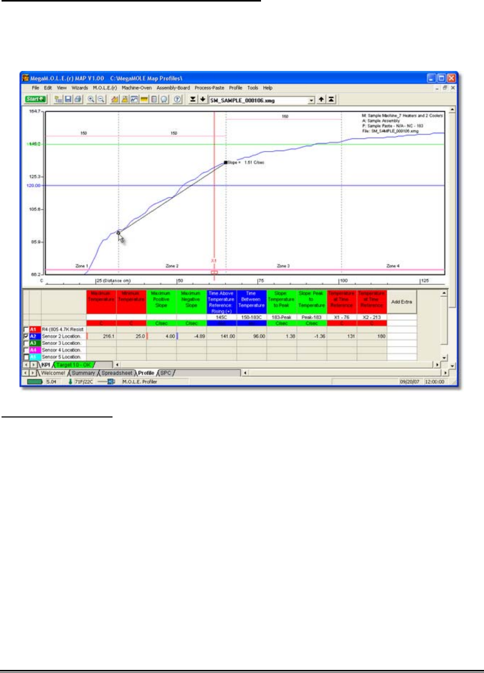
To remove a slope line from the Data Graph:
1) Using the mouse pointer, select the object on the Data Graph by clicking it once.
The object trackers will then become bold indicating that it has been selected.
2) Press the [Delete] key on the keyboard to remove the object.
Slope Applications
• Use the Slope tool to find the average slope between any two points on the
graph. Longer slope lines tend to produce more accurate slope calculations.
• The Slope tool can be used to compare actual data with ideal conditions by
drawing a line with a known slope (to represent the ideal condition) beside a
portion of a Data Plot.

♦335♦ MEGAM.O.L.E.® Help System Guide
Slope Limitations
• Slope calculations are based on logged points connected by the slope line.
Points occur only at the exact time intervals used to record data.
• The Slope tool cannot measure slopes when the line is vertical.
This command can be accessed on the Toolbar when the Profile Tab is active.
Slope Button
MEGAM.O.L.E.® Help System Guide ♦336♦
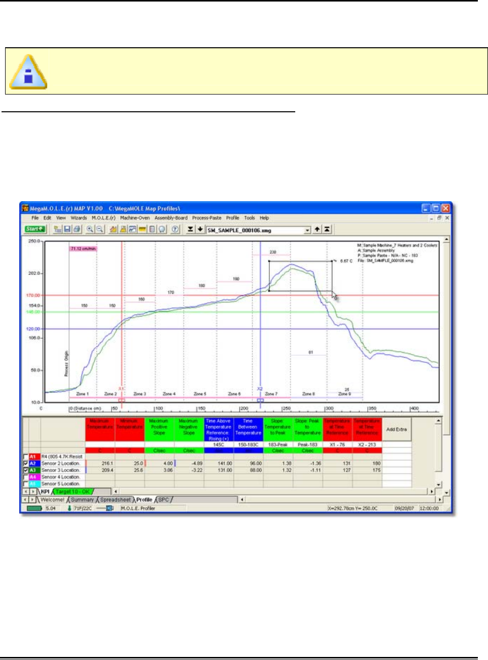
5.5.10.3. Peak Difference
This command displays the difference in value between the peak of the maximum Data
Plot and the peak of the minimum Data Plot in any location of the Data Graph. This
command is especially useful for measuring side-to-side heating differences in ovens.
The peak difference is calculated as the maximum difference between the
highest peak and the lowest peak within the rectangle.
To display the peak difference between Data Plots:
1) On the Tools menu, click Peak Difference.
2) Position the mouse pointer on a corner of the area you want to analyze.
3) Press the left mouse button and drag the pointer diagonally to the opposite
corner to form a Peak difference box. An outline of the box appears as you drag.
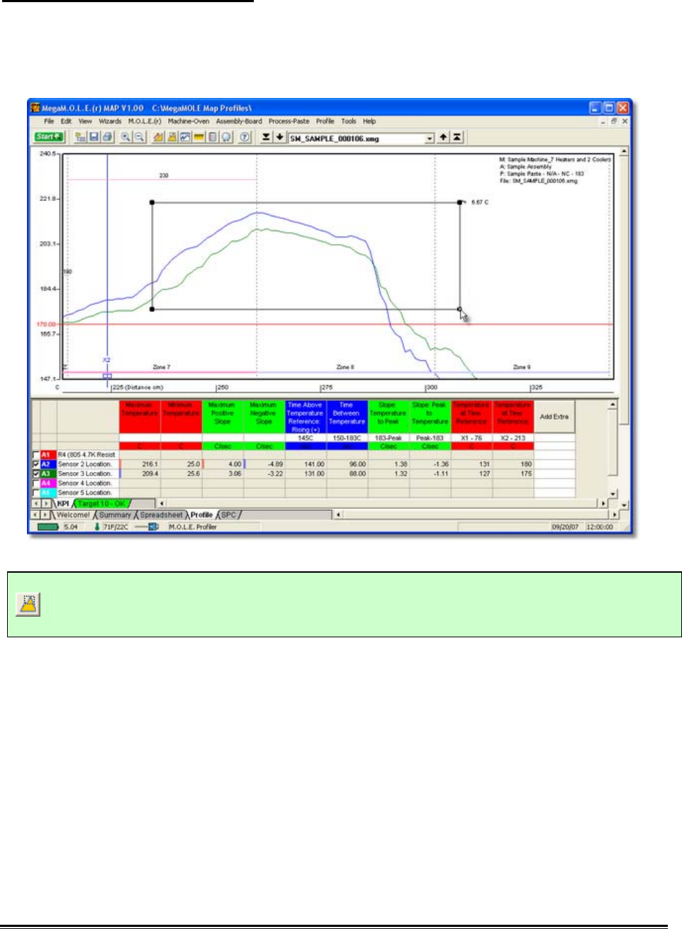
♦337♦ MEGAM.O.L.E.® Help System Guide
To remove the peak difference:
1) Using the mouse pointer, select the object on the Data Graph by clicking it once.
The object trackers will then become bold indicating that it has been selected.
2) Press the [Delete] key on the keyboard to remove the object.
This command can be accessed on the Toolbar when the Profile Tab is active.
Peak Difference Button
MEGAM.O.L.E.® Help System Guide ♦338♦
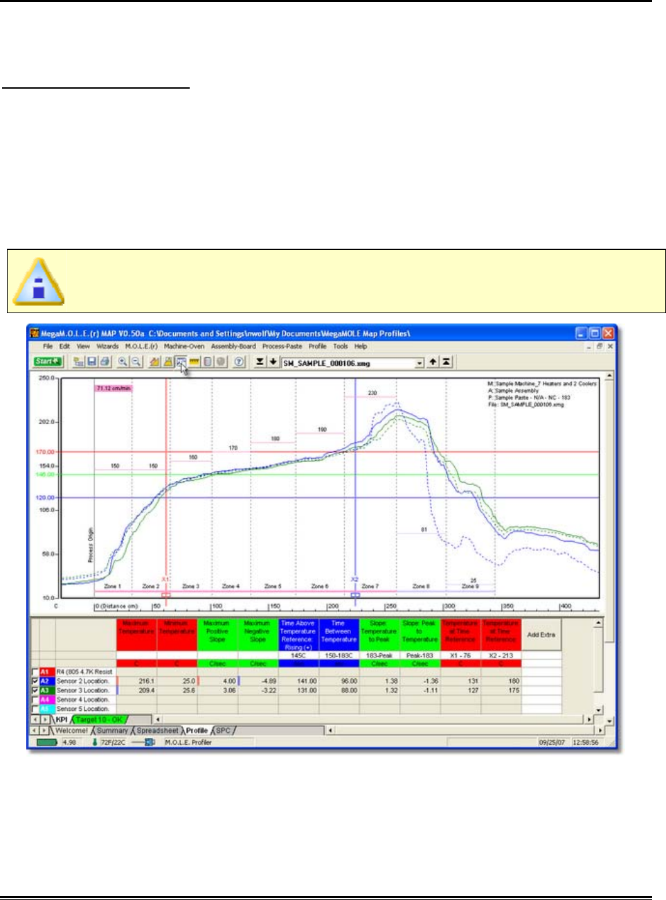
5.5.10.4. Overlay
The Overlay tool displays a second data run profile over the currently displayed profile
on the Data Graph for comparison.
To overlay two Profiles:
1) On the Tools menu, click Overlay. A list box of data run files (.XMG) in the
currently selected working directory appears.
2) Select a data run file (.XMG) to overlay on the original.
The profile will be inserted at the same process origin and automatically scaled to the
same Temperature (Y) axis. The original Data plots remain as solid lines while those
added for comparison are dashed.
The dashed “Overlay” Data Plots are the same color as the original Data Plots.
♦339♦ MEGAM.O.L.E.® Help System Guide
To remove the overlaid Data Graph:
1) Select the Overlay command again.
Overlay Applications
• The Overlay and Magnify tools can be used together to overlay and compare
ideal reference profiles and magnified portions of the two data files. They can
have different but overlapping Time (X) values (times, point numbers, logging
intervals) or temperatures.
Overlay Limitations
• If the Data Plots are too numerous to clearly see the information of interest, they
can be suppressed by turning the desired channel in one or both files "OFF".
This must be done to the overlaid data run file prior to using the Overlay tool.
Save that data run file and use the Overlay tool again.
This command can be accessed on the Toolbar when the Profile Tab is active.
Overlay Button
MEGAM.O.L.E.® Help System Guide ♦340♦
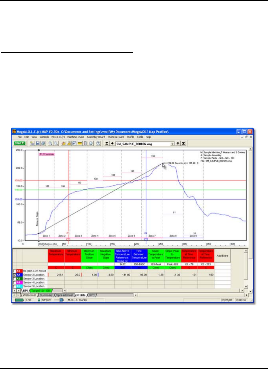
5.5.10.5. Measure
The Measure tool is similar to the Slope tool except it measures the distance between
any two points on the Profile worksheet Data Graph. This tool adds a line labeled with
the distance values to the graph, and notes the change in X and change in Y (Delta X
and Delta Y) instead of the slope. »
To find the distance between two points:
1) On the Tools menu, click Measure.
2) Position the mouse pointer at a point on the curve.
3) Press and hold the left mouse button.
4) Drag the pointer to the end of the desired point on the curve.
5) Release the left mouse button when the pointer is at the desired location and a
slope line labeled with the change in X and Y appears on the Data Graph.
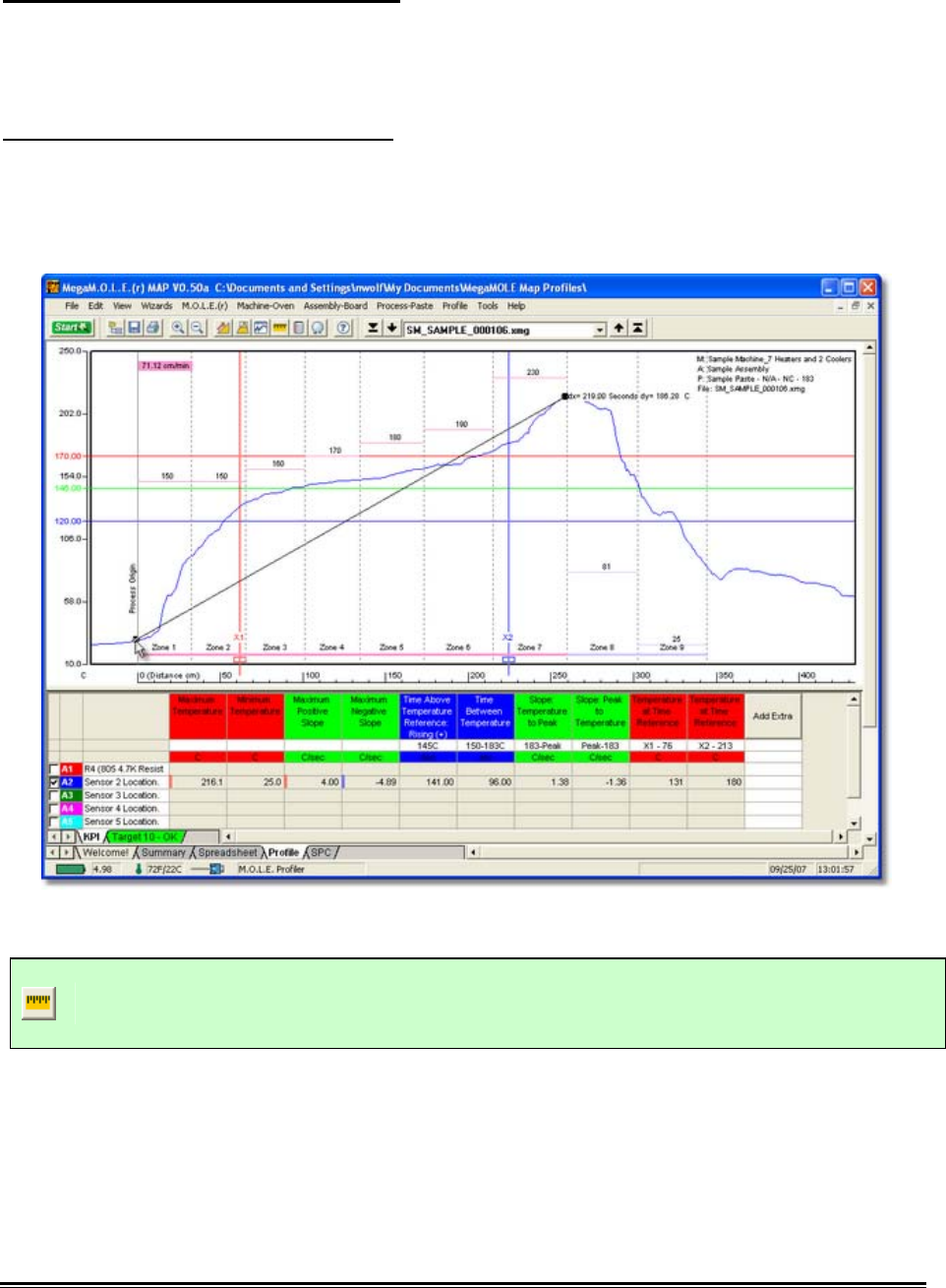
♦341♦ MEGAM.O.L.E.® Help System Guide
To obtain more accurate distances:
1) Magnify a portion of the Data Graph using the Magnify tool and repeat this
procedure.
To remove the annotated distance:
1) Using the mouse pointer, select the object on the Data Graph by clicking it once.
The object trackers will then become bold indicating that it has been selected.
2) Press the [Delete] key on the keyboard to remove the object.
This command can be accessed on the Toolbar when the Profile Tab is active.
Measure Button
MEGAM.O.L.E.® Help System Guide ♦342♦
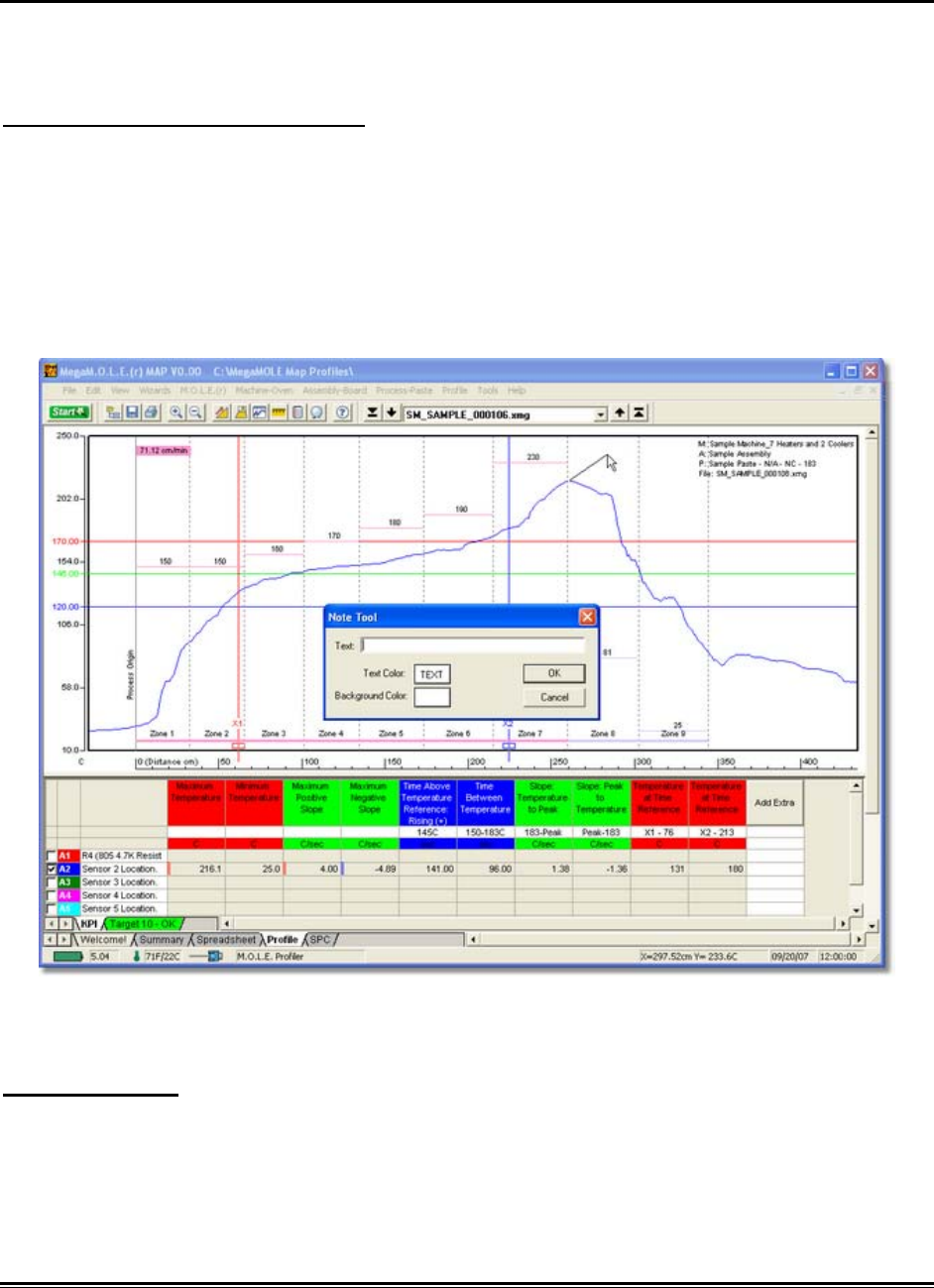
5.5.10.6. Notes
The Notes tool adds a leader with text to any portion on the Data Graph to label special
points of interest.
To add notes to the Data Graph:
1) On the Tools menu, click Notes.
2) Position the mouse pointer at the desired location to start the note leader, click
and drag the mouse pointer to the desired location for the note text and release
the mouse button.
3) A dialog box appears allowing the user to enter a note by typing it in the text box.
There also are options to customize the color and font size.
4) Click the OK command button or Cancel to quit the command.
To move notes:
1) Select a note leader, click and drag the mouse pointer to the desired location for
the note and release the mouse button.
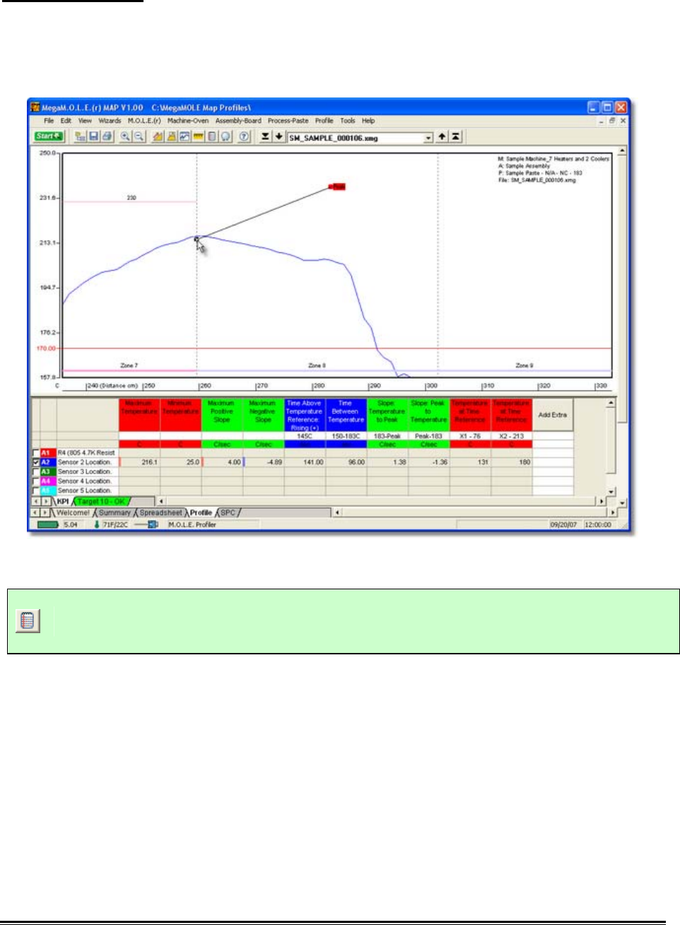
♦343♦ MEGAM.O.L.E.® Help System Guide
To remove notes:
1) Using the mouse pointer, select the object on the Data Graph by clicking it once.
The object trackers will then become bold indicating that it has been selected.
2) Press the [Delete] key on the keyboard to remove the object.
This command can be accessed on the Toolbar when the Profile Tab is active.
Notes Button
MEGAM.O.L.E.® Help System Guide ♦344♦
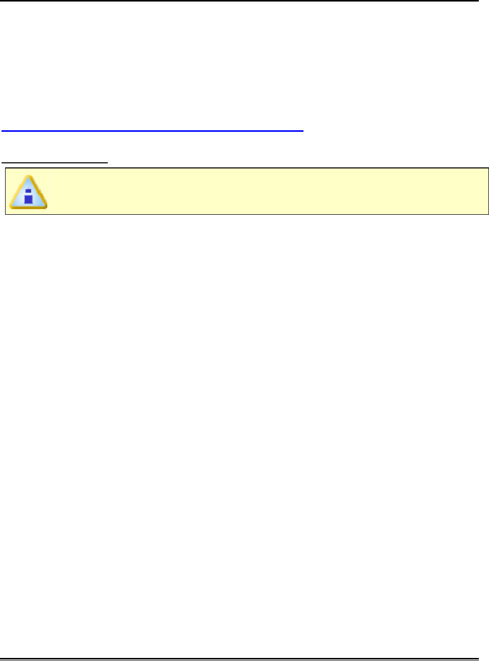
5.5.10.7. Prediction
One of the most impressive software features is the Prediction tool. This tool enables
the user to change a zone temperature value or the conveyor speed and predict the
outcome of that change. Prediction is easy to use and a valuable command that quickly
defines process parameters.
To use the Prediction Tool machine information must first be set to build an accurate
“model” of an oven environment. As experience with modeling grows, the first values
selected may need to be modified accurately reflect the process. Refer to topic
Software>Menus>Machine>Set Machine Information.
To predict results:
If Zone temperatures are not set, the Prediction tool will not work.
1) On the Tools menu, click Prediction and the Prediction pallet appears.
♦345♦ MEGAM.O.L.E.® Help System Guide
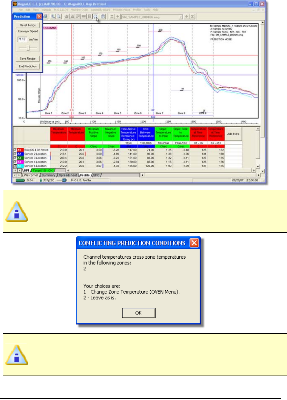
If sensor temperatures are inconsistent with zone temperature settings, a
message box with an explanation appears. The explanation appears only once
for all zones, each time Prediction is used. After that, the software assumes the
user is aware of the potential problem.
The inconsistent setting does not prevent the software from making a
prediction. It makes a rational assumption about what is happening. In addition
to the explanation, several logical ways are displayed to correct the conflicting
conditions at the bottom of the dialog box.
MEGAM.O.L.E.® Help System Guide ♦346♦
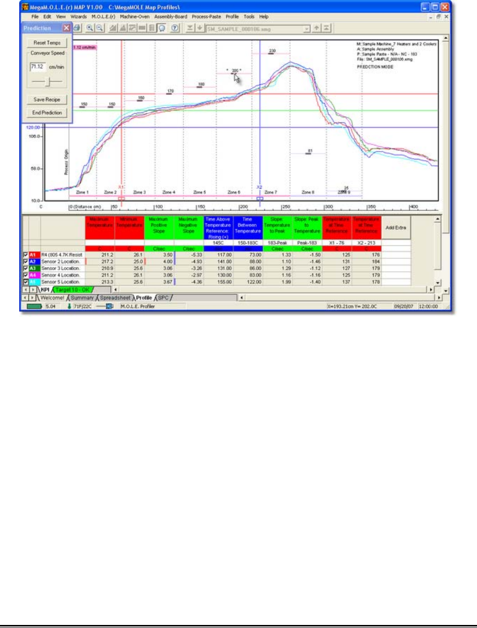
2) Experiment by making “what if” changes to the conveyor speed and sliding Zone
Temperature Prediction Handles up or down to the preferred prediction
temperature.
3) Once the predicted machine recipe is at the desired settings, the user can save
them to a recipe file (.XMR) or print them by selecting the Save Recipe
command button.
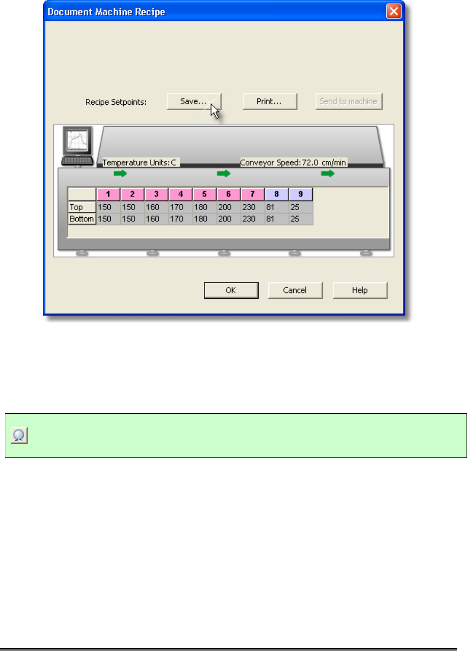
♦347♦ MEGAM.O.L.E.® Help System Guide
4) Once the machine recipe is saved, set the machine to the final prediction values,
let it stabilize and then perform another data run to check if the process has been
optimized.
This command can be accessed on the Toolbar when the Profile Page Tab is active.
Prediction Button
MEGAM.O.L.E.® Help System Guide ♦348♦
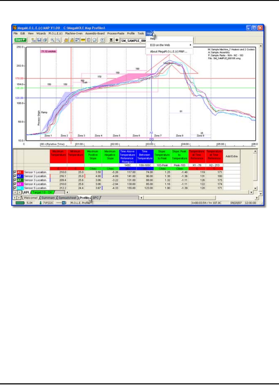
5.5.11. Help Menu
The Help menu commands are useful when information is needed quickly or when this
Users guide is not available.
♦349♦ MEGAM.O.L.E.® Help System Guide
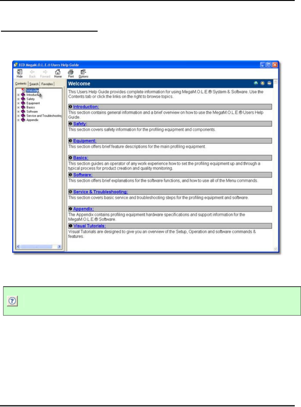
5.5.11.1. Help
The Help Index is a complete reference tool that can be used at any time.
To launch the help system:
1) On the Help menu, click Help to launch the user’s help guide. You may now
search for the help topic of your choice.
This command can be accessed on the Toolbar and can also be used by pressing the
shortcut key [F1].
Help Button
MEGAM.O.L.E.® Help System Guide ♦350♦
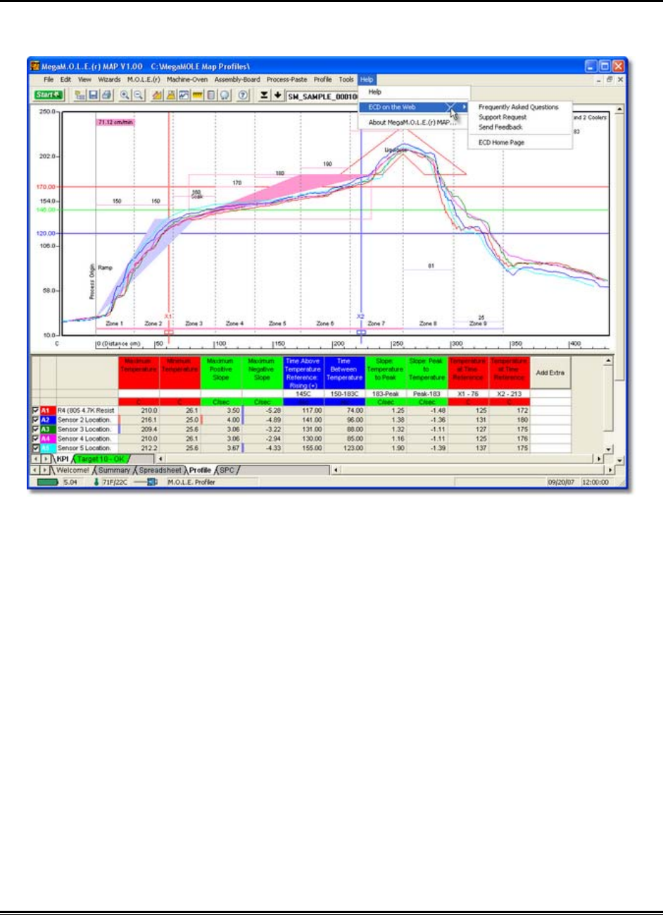
5.5.11.2. ECD on the Web
You can access more help by using ECD web commands. Let us help you by using the
linked commands to the ECD Web site.
♦351♦ MEGAM.O.L.E.® Help System Guide
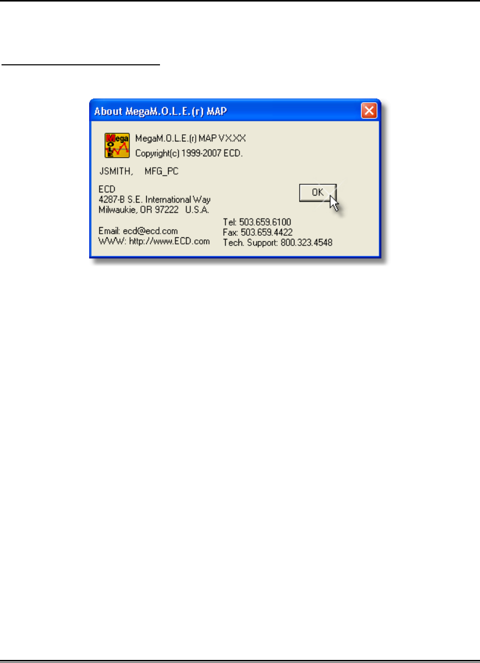
5.5.11.3. About MEGAM.O.L.E.® MAP
The About command displays the software version, release date and company
information.
To view About information:
1) On the Help menu, click About MEGAM.O.L.E.® MAP.
MEGAM.O.L.E.® Help System Guide ♦352♦
6.0 Service and Troubleshooting
6.1. General Service Information
This section covers maintaining and troubleshooting a M.O.L.E., Thermocouples, Power
Pack battery, Software, Wiring, and other parts of the system.
The following service and calibration instructions are for use by qualified
personnel only. Refer to the Safety>Operators Safety Information prior to
performing any service.
Service Troubleshooting:
Decide if the problem is with the M.O.L.E. profiler Hardware, Communications, or
Software.
• If the problem occurs while attempting to log data, the Hardware may be faulty.
• If the problem occurs while attempting to communicate between M.O.L.E. profiler
and the computer, the Communications links may be faulty.
• If the problem occurs while attempting to use a software function, the software
may be faulty.
Once it has been determined what item is causing the problem, refer to the appropriate
service section. Start at the top of the list and work your way down. If the problem is still
unresolved go to Service>How to Get Additional Help.

♦353♦ MEGAM.O.L.E.® Help System Guide
6.2. MEGAM.O.L.E.®
This section describes problems that can occur with M.O.L.E. profiler hardware.
Hardware Problems:
Wrong or erratic temperature readings:
• Open or intermittent thermocouple, cable, or connector: Individual channels
being detected as “Open” on the profile plot will indicate this. Check
thermocouple wires and insulation. Also, check the connectors visually for
damage or loose connections. Tighten all the connections and check with an
ohmmeter or millivolt meter if available or substitute a thermocouple that you
know works properly.
• Shorted thermocouple, cable, or connector: This is harder to find. A shorted
thermocouple connector or cable creates a new thermocouple junction at the
location of the short; therefore, actual temperatures are recorded, but not the
ones desired. If the short is intermittent, the recorded temperatures may jump
between that of the thermocouple and that of the shorted location. Visually check
for shorts inside of connectors and for damaged insulation on the wires. Repair
or replace any suspicious components.
• Wrong type thermocouple, connector, or wire: Wrong thermocouple types will
give consistently wrong readings, either always high or always low. Wrong
connectors or wrong wire types (used as an extension) create extra
thermocouple junctions and uncontrolled temperature offsets. Use only Type K
thermocouple wires, and connectors.
• Thermocouple connector wired backwards: Typically causes high
temperatures to read as negative (e.g., -150°F.). Should be Yellow=Ch, Red=Al.
• Low power pack charge: Charge the power pack.
• Conductive contamination inside the M.O.L.E. profiler or I/O Module:
Although unlikely, this is known to cause “spikes” (abrupt jumps in value) in the
recorded temperatures. Other kinds of errors are also possible.
• Incorrect calibration: If the recorded temperatures for all of the active channels
are wrong in the same direction (e.g., all too high), then possibly the I/O Module
has incorrect calibration. Refer to topic Service>MEGAM.O.L.E.>Calibration
Information for cautions and procedures, or return the M.O.L.E. profiler to ECD
for re-calibration.
• Internal temperature effects: If the M.O.L.E. profiler and it's components has
been subjected to an internal temperature in excess of the published
specifications. Temperatures outside the specified operating range may cause
incorrect readings and shorten Power Pack life. Internal temperatures in

MEGAM.O.L.E.® Help System Guide ♦354♦
excess of the absolute maximum warranteed internal temperature may
cause permanent, irreparable damage to your MEGAM.O.L.E. profiler.
• M.O.L.E. profiler never turns on, but the software can read and write the
hardware configuration: The start switch is possibly defective, return to ECD
for service.

♦355♦ MEGAM.O.L.E.® Help System Guide
6.2.1. Communications Problems
“Instrument not responding” error message:
• Try triggering the M.O.L.E. profiler with the switch. If you cannot get the light to
flash, you have a hardware problem with the M.O.L.E. profiler itself.
If you can activate the M.O.L.E. profiler with the switch, check for the following:
• Wrong computer communication port: Cable must be connected to which is
selected using the Select Instruments command in the software.
• Conflicting use of COM port: Perhaps some other software, such as a mouse
driver, communications programs, or PDA is trying to use the same COM port.
• Computer Interface cable defective: Order spare or replacement cables from
ECD, refer to Service>How to Get Additional Help for contact information.
MEGAM.O.L.E.® Help System Guide ♦356♦
6.2.2. Calibration Information
Because the MEGAM.O.L.E. profiler and I/O Module are made with precision
components with high temperature stability and tight tolerances; the analog-to-digital
converter remains stable for years. High quality components together with software
algorithms based on the ITS-90* standard for Type K thermocouples have been
provided to yield specified accuracy and long-term stability. Each unit has been tested
at the factory before it is shipped.
ECD recommends the MEGAM.O.L.E. profiler I/O Module is factory re-
calibrated every 6 months when it is being used constantly. If the use is
occasional, a period of no greater than 12 months between calibrations is
recommended.
Depending on use, however, temperature accuracy should be periodically verified using
a suitable temperature standard. Any observed inaccuracies are probably not caused by
calibration error but by any one of a number of other sources, primarily the following:
1) Poor thermocouple connectors or open thermocouples.
2) Using a temperature standard that is inaccurate or is not traceable to the
National Institute of Standards and Technology (NIST, formerly the Nation
Bureau of Standards).
• Check the accuracy of your temperature standard and that it is traceable to NIST.
Be sure that you’re using Type K wire connected to the standard. Be sure that
your temperature standard is cold-junction compensated, or use an ice point
reference.
3) Extremely low Power Pack battery charge.
• Recharge the Power Pack battery. Refer to topic Basics>Setup>Charging the
Power Pack Battery.
4) Sudden changes or excessive ambient temperatures.
• Allow MEGAM.O.L.E. profiler temperature to stabilize for 1/2 hour before
calibration.
If after checking these possible sources of inaccuracy the MEGAM.O.L.E. profiler I/O
Module still needs to be calibrated, contact ECD for the proper calibration procedure
P/N A47-6342-05.
If you need to return the MEGAM.O.L.E. profiler I/O Module for re-calibration, contact
ECD and request an RMA (Return Merchandise Authorization). Refer to section How to
Get Additional Help for contact information.
*ITS-90 (International Temperature Scale of 1990)
♦357♦ MEGAM.O.L.E.® Help System Guide
6.2.3. Constructing a Thermocouple
The following procedures describe how to construct a nano thermocouple and a
protective plug.
Thermocouple construction:
The following items will be needed to construct a Thermocouple:
• 1 nano thermocouple housing and 2 hardware screws.
• Up to five Thermocouples.
• Phillips (Crosshead) screwdriver
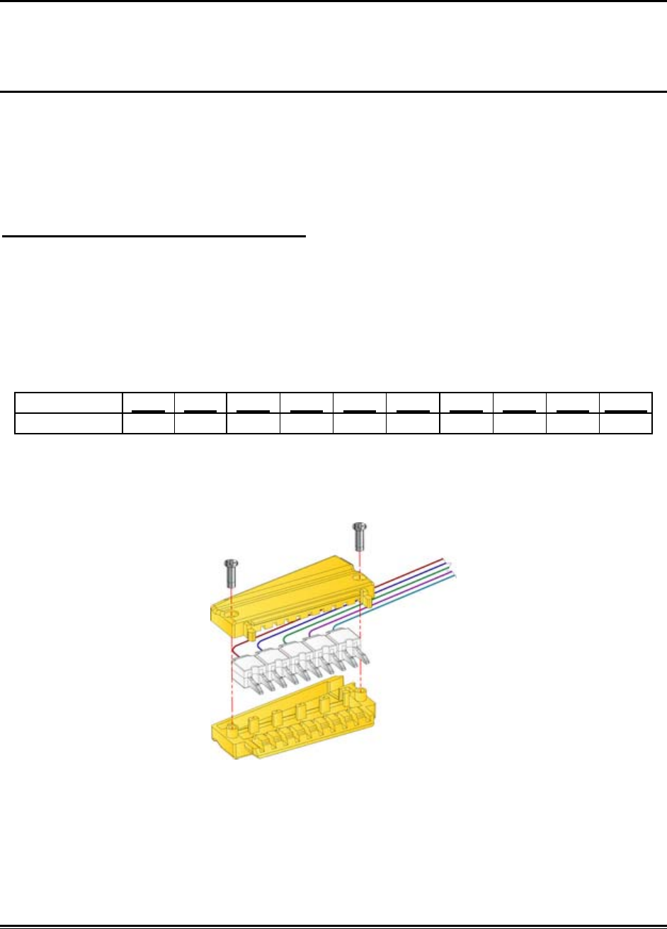
Construct a thermocouple as follows:
1) Disassemble the thermocouple housing by unscrewing the 2 Phillips hardware
screws.
2) Remove the existing thermocouple(s).
3) Insert the new thermocouple(s) in the top half of the thermocouple housing until
they are fully seated. Be careful to place them in the proper color arrangement
per the table below.
Channels: 1/11 2/12 3/13 4/14 5/15 6/16 7/17 8/18 9/19 10/20
Color: Red Blue Green Violet Cyan Red Blue Green Violet Cyan
4) Route the wires through the housing exit.
5) Carefully place the two halves of the thermocouple housing together. Verify that
the wires are not pinched and that the wire positions are correct.
6) Replace the hardware screws.
MEGAM.O.L.E.® Help System Guide ♦358♦
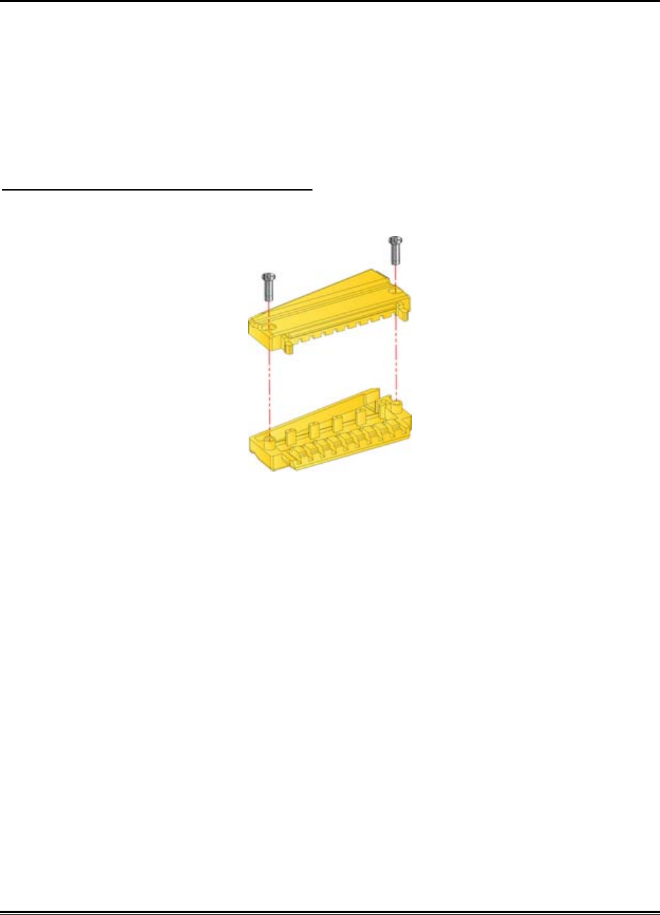
Protective plug construction
If fewer than four nano connectors (20 sensors) are used in your application, a
protective plug may be used for each of the unused I/O Module channel banks.
The following items will be needed to construct a Thermocouple:
• 1 nano thermocouple housing and 2 hardware screws.
• Phillips (Crosshead) screwdriver
Construct a protective plug as follows:
1) Carefully place the two halves of the thermocouple housing together.
2) Replace the 2 hardware screws.

♦359♦ MEGAM.O.L.E.® Help System Guide
6.3. How to Get Additional Help
If you still have problems, let us help you. We offer many ways to service your
problems. You can call our Service/Test technicians, visit our web site to view our FAQ
section (Frequently asked Questions) or send us e-mail explaining your problem in
detail.
When calling our Service/Test technicians or sending us e-mail, please include the
following information:
• Product Description (i.e.MEGAM.O.L.E.)
• Product Serial Number
• Software Version
Here is how to contact ECD:
Telephone: +(1) 800.323.4548
+(1) 503.659.6100
FAX: +(1) 503.659.4422
Technical Support: +(1) 800.323.4548
Email: ecd@ecd.com
Internet: http://www.ecd.com
MEGAM.O.L.E.® Help System Guide ♦360♦
Appendix
A: Specifications
MEGAM.O.L.E. 20 Profiler
I/O Module:
INPUTS: Up to 20 type K ECD Nano-Thermocouples
PHYSICAL DIMENSIONS: 63.5mm x 75.4mm x 7.2mm (2.50" x 2.97" x 0.28")
TEMPERATURE MEASUREMENT RANGE: -129°C to +1272°C (200°F to +2322°F)
INTERNAL OPERATING TEMPERATURE RANGE: -40°C to 85°C (-40°F to 185°F)
Absolute Maximum Warranteed Internal
Temperature: 82°C (180°F)* MEGAM.O.L.E. I/O Module
automatically stops operating when the internal
temperature exceeds 85°C (185°F)
*WARNING: Exceeding this temperature may permanently damage the equipment!
ACCURACY: ±1°C. Channel to channel compliance within 1°C.
PROGRAMMABLE SAMPLING PERIOD: 0.1 seconds to 24 hours
OPEN THERMOCOUPLE DETECTION. All 20 channels
NUMBER OF SAMPLES PER CHANNEL 100,000 total for 20 channels
Main Module:
PHYSICAL DIMENSIONS: 63.5mm x 63.5mm x 7.2mm (2.50" x 2.50" x 0.28")
INTERNAL OPERATING TEMPERATURE RANGE: -40°C to 85°C (-40°F to 185°F)
Absolute Maximum Warranteed Internal
Temperature: 82°C (180°F)* MEGAM.O.L.E. Main Module
automatically stops operating when the internal
temperature exceeds 85°C (185°F)
*WARNING: Exceeding this temperature may permanently damage the equipment!
HARDWARE REAL-TIME CLOCK/CALENDAR: ±1 minute/month at 25°C
♦361♦ MEGAM.O.L.E.® Help System Guide
Power Pack Battery:
PHYSICAL DIMENSIONS: 63.5mm x 38.2mm x 7.2mm (2.50" x 1.50" x 0.28")
POWER PACK CHARGE: Typical 50 ten-minute profiles.
CHARGE TIME: 8 hours (a 15 min. charge allows one 10min. data
run)
EXPECTED POWER PACK LIFE: 300-400 charging cycles.
OPERATING RANGE: 4.2V to 3.0V
Power Pack Battery Charger:
INPUT: Voltage Rating: 100 to 240 VAC
Current: 200mA(RMS) max. @ 115VAC
80mA(RMS) max. @ 230VAC
Frequency: 50/60Hz
OUTPUT: 5V DC, Load 0A MIN. 1A MAX.
Mains Voltage Fluctuations: + 10%
Wireless RF Option:
This equipment has been tested and found to comply with the limits for a Class A digital device, pursuant to
Part 15 of the FCC Rules. These limits are designed to provide reasonable protection against harmful
interference in a residential installation. This equipment generates, uses and can radiate radio frequency
energy and, if not installed and used in accordance with the instructions, may cause harmful interference to
radio communications. However, there is no guarantee that interference will not occur in a particular
installation. If this equipment does cause harmful interference to radio or television reception, which can be
determined by turning the equipment off and on, the user is encouraged to try to correct the interference by
one or more of the following measures:
• Reorient or relocate the receiving antenna.
• Increase the separation between the equipment and receiver.
• Connect the equipment into an outlet on a circuit different from that to which the receiver is connected.
• Consult the dealer or an experienced radio/TV technician for help.
Thermocouple Specifications:
Thermocouples: Type K, Micro-Connector, Teflon insulated. (Other insulation types available.)
THERMOCOUPLE RESPONSE TIME
Wire Size Still Air
800/100°F 60 Ft./Sec. Air
800/100°F Still H2O
200/100°F
.005 in. 1.0 sec. 0.08 sec. 0.04 sec.

MEGAM.O.L.E.® Help System Guide ♦362♦
Environmental Limitation Specifications:
MegaMOLE Profiler:
• Maximum relative humidity 80% RH from 0°C to 31°C, decreasing linearly to 17% RH at 50°C.
• Pollution Degree 2 (Normally only dry pollution, but with temporary conductivity caused by condensation)
Power Pack Charger:
• Temperature: (Operation) 0 to +45°C (32 to 113°F)
• Temperature: (Non-Operation) -20 to +75°C (-4 to 167°F)
• Humidity: (Operation) 20 to 90%
NOTE:Tests have shown that because of the sensitive nature of the measurement and logic circuits, the
following precautions must be observed:
• Minimize exposure to ESD Events. If the M.O.L.E. profiler or one of the thermocouples receives an
8kV electrostatic discharge during the data collection sequence, the M.O.L.E. profiler may switch itself
“OFF”. To retrieve the data, simply upload the data that was recorded prior to the event. If a new data
collection sequence is started without uploading first, the existing data stored in the M.O.L.E. profiler will
be lost.
• Keep strong electromagnetic fields away. The thermocouple wires serve as an antenna for
electromagnetic radiation. If field strength of 3 volts per meter is present (usually due to close proximity
of radio transmitters) while the M.O.L.E. profiler is collecting data, the accuracy of the data may be
compromised. This interference is compounded by using long thermocouple wires, as well as the effect
of the thermocouple wires acting as a “tuned” antenna.

♦363♦ MEGAM.O.L.E.® Help System Guide
B: Statistical Process Control (SPC) Background Information
This appendix deals with the subset of SPC that is incorporated into MAP Software. It
does not address general SPC principals. A working knowledge of general statistical
principals and SPC terms is assumed and is not addressed here. There are many good
basic SPC books where this information may be obtained.
Reflow and Wave Solder operators, engineers and production managers are expected
to understand their soldering process so as to deliver quality products cost effectively.
This is a continuous process.
First, the machine must be checked for consistency. A standard or typical set up should
be routinely checked prior to any process set point determinations, or actual production
run machine checks. Only after the machine has been determined to be operating
correctly and not experiencing abnormal variation, should data from the machine be
utilized. SPC is all about identifying common or normal variation from abnormal
variation.
Second, the correct process set points must be determined for a particular product.
Utilizing the M.O.L.E. profiler, the correct set points for a particular product may be
determined. These set points, if selected correctly and followed, should deliver the
maximum throughput of quality product.
Third, the machine must consistently deliver the correctly determined set points. SPC
will help identify common or normal variation from abnormal variation. Checking the
machine using your M.O.L.E. profiler and the MAP Software with its SPC capability will
help ensure that the machine is consistently performing to its set points and your
expectations.
Fourth, repeat the above three steps. Continuous improvement is a never-ending cycle.
Check the long-term variation of the machine by graphing typical set point samples.
Using the M.O.L.E. profiler, recheck/adjust part number specific set points to maximize
your quality throughput. Check the machine during a part number run to control the
machine variation from that part number’s actual ideal set points.
While SPC had its start in high volume repetitive operations, SPC is applicable to many
other types of operations as well. However, SPC can be difficult to apply to short runs.
Short runs may be runs that take a long time to process, runs in which multiple samples
are difficult to collect, and runs where samples are difficult to place into subgroups or
runs where small quantities are run.
The MAP Software charts will be more meaningful to the user if SPC charts are
generated based on data sets that have the same set points each time.
MEGAM.O.L.E.® Help System Guide ♦364♦
There are several basic short run SPC techniques:
1. Nominals Charts
2. Individuals/Moving Range Charts
3. Moving Average/Moving Range Charts
4. Standardized Formula Charts
The Moving Average/Moving Range Chart technique is particularly well suited for
situations where control information is desired as soon as possible and there is a
relatively long time between sample collections. After considering the nature of solder
operations and the machine sampling process, the Moving Average/Moving Range
Chart technique was incorporated into MAP Software.
Moving Average/Moving Range Chart Technique:
MAP Software utilizes the standard Moving Average/Moving Range Charting technique
with a subgroup size of 2-6 that is selected by the user. The following steps and figure
illustrates the Moving Average/Moving Range calculations (using a group size of two)
that are used to construct the SPC chart.
Steps for Creating a Moving Average Moving Range Control Chart:
1. Select the key variable to monitor.
2. Select the moving average group size. (We will use two in our example.)
3. Obtain your first sample and record it as sample 1 (X1).
4. Obtain your second sample and record it as sample 2 (X2).
5. Determine the x-bar and R values.
Moving Average formulas:
X
1 +
X
2
2
X =
(
Ran
g
e
)
R=X - X
H
L
6. Plot this value on the chart as subgroup 1.
7. Carry forward sample 2 into subgroup 2’s calculation. Obtain your third sample
and record it as sample 3. The averages of sample 2 and sample 3 form
subgroup 2.
8. Plot this value on the chart as subgroup 2.
9. Repeat for all the samples.
10. Calculate control limits using standard x-bar and R formulas for the
appropriate sample sizes. MAP Software uses range-based calculations for LCL
and UCL.
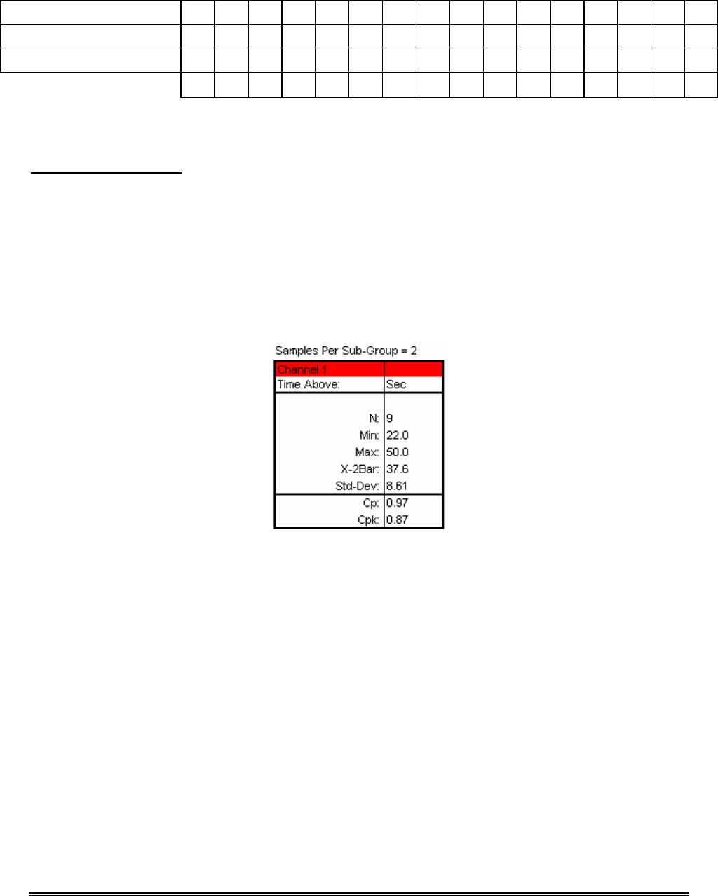
♦365♦ MEGAM.O.L.E.® Help System Guide
11. Continue monitoring the process.
SAMPLE # 1 2 3 4 5 6 7 8 9 10 11 12 13 14 15 16
SAMPLE MEASUREMENTS 3 4 5 3 2 9 5 2 6 8 4 8 5 6 3 3
SUBGROUP VALUE x 3.5 4.5 4 2.5 5.5 7 3.5 4 7 6 6 6.5 5.5 4.5 3
R 1 1 2 1 7 4 3 4 2 4 4 3 1 3 0
Moving Average/Moving Range Subgroup Size 2 Calculations Chart
Process Capability
A process capability index is a standard measure of how a process compares with its
specification limits—how a process is performing relative to how it is supposed to
perform. As opposed to the control chart, which shows detailed information about how
the data compares with control limits, a capability index is a summary of how the data
compares with the specification limits.
Two common capability indicators are Cp and Cpk. These values are shown in the
Statistics Box on the SPC Page Tab.
For both of the index values, the data used to determine them is dictated by the
subgroup size (N) chosen by the user. In the case where N=1, individual data is used—
for N>1, average data is used (x bar).
The charts on the next page give a graphical representation of the concept of Cp and
Cpk. Notice that in each graph, the same upper and lower specification limits (USL,
LSL) are used. The values of Cp and Cpk will differ according to the data that is
compared with those specifications.
Depending on the particular process being monitored, the desired value for Cp and Cpk
may differ. In general, however, a Cp and Cpk of 1.33 or above is desired. This assures
that the process is not only capable of meeting the required specification limits, but also
has a built-in margin for error that may be needed in special circumstances. In addition
to targeting a certain minimum Cp and Cpk, it is also desirable to have these two values
equal one another. This indicates that the process is well-centered between the
specification limits.
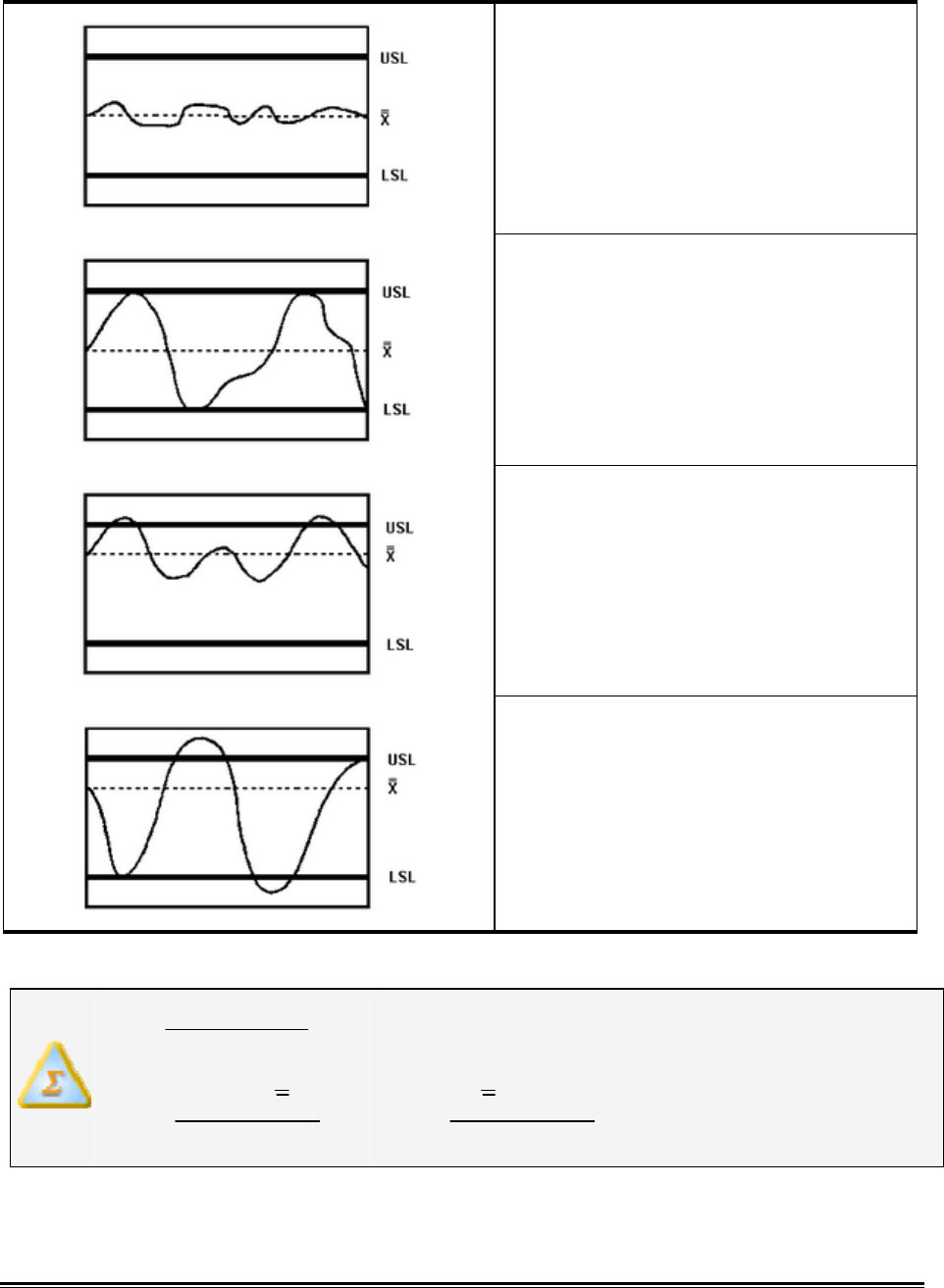
MEGAM.O.L.E.® Help System Guide ♦366♦
Cp ≥ 1.33: Data tightly distributed.
Cpk ≥ 1.33: Data well inside spec limits.
Cp = 1.00: Data fills entire spec range.
Cpk = 1.00: Data fills entire spec range.
Cp > 1.00: Data tightly distributed. If it
were centered between the spec limits,
no data would lie beyond those limits.
Cpk < 1.00: Some data is outside the
spec limits.
Cp < 1.00: Data not tightly distributed. If
it were centered between the spec limits,
some data would still lie outside those
limits.
Cpk < 1.00: Some data is outside the
spec limits.
The equations used to calculate the index values are as follows:
.).(*6 DevStd
LSLUSL
Cp −
=
.).(*3 DevStd
xUSL
Cpk −
=O
R .).(*3 DevStd
LSLx
Cpk −
=, whichever is less
As can be interpreted from the above equations, Cp gives an indication of how narrow
the data distribution is relative to the width of the specification limits. Essentially, it

♦367♦ MEGAM.O.L.E.® Help System Guide
indicates how well the process would be able to stay within the specified limits if the
data were perfectly centered between those limits.
Cpk compares the widest half of the data distribution to the appropriate specification
limit. It indicates whether the process is capable of meeting the specification as
indicated by the “worst half” of the measurements. Unlike Cp, the Cpk index measures
process capability without assuming the data is well-centered.
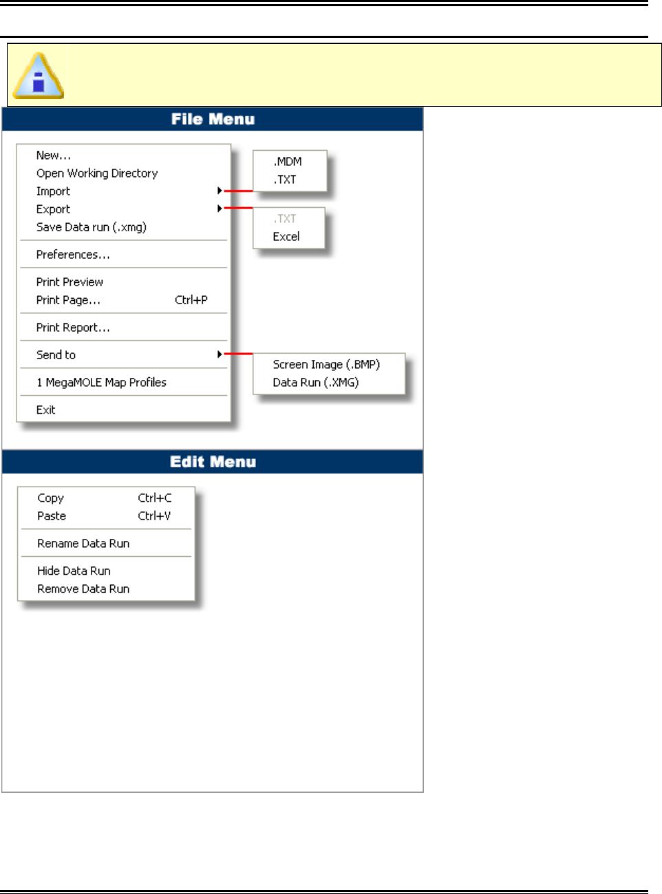
MEGAM.O.L.E.® Help System Guide ♦368♦
C: Pull Down Menus & Toolbar Buttons
Menus:
The dimmed menu commands are used in other Page Tabs.
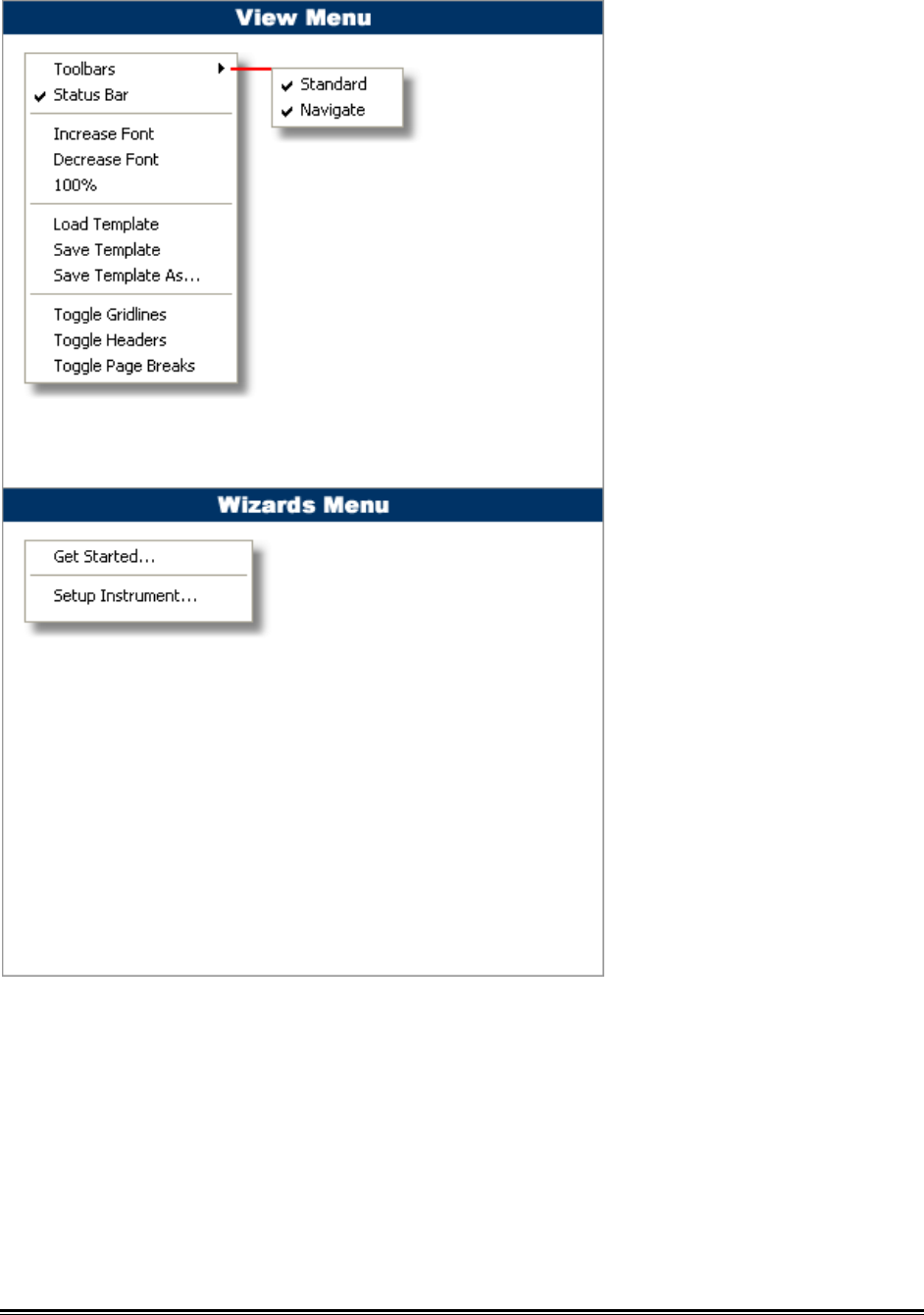
♦369♦ MEGAM.O.L.E.® Help System Guide
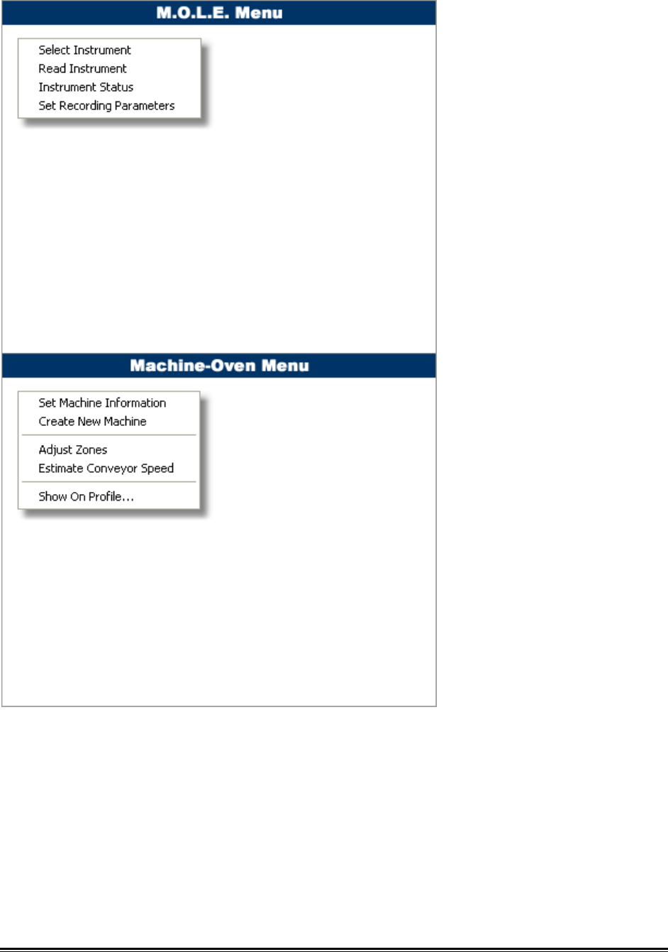
MEGAM.O.L.E.® Help System Guide ♦370♦
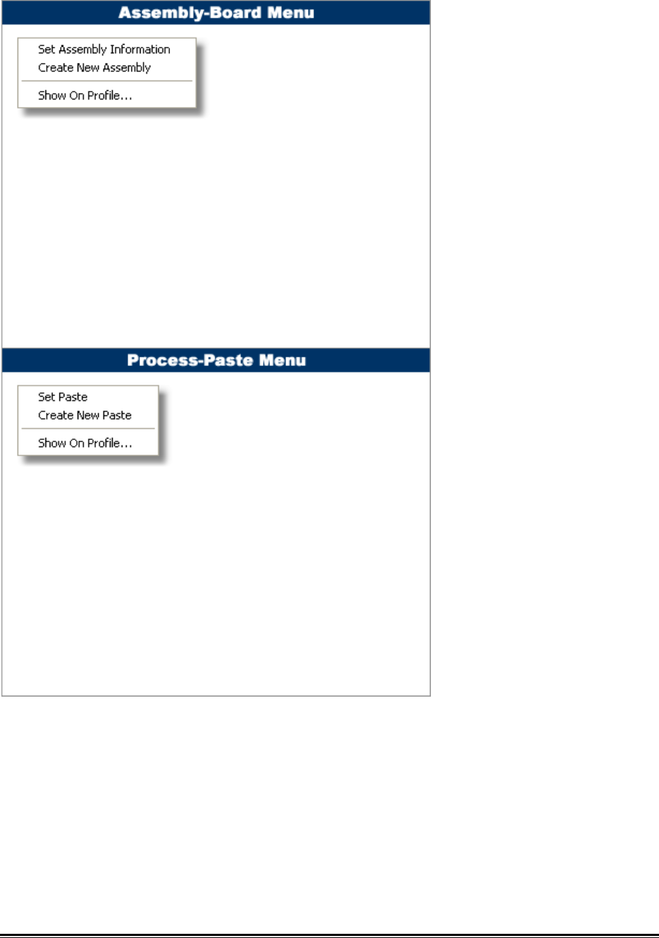
♦371♦ MEGAM.O.L.E.® Help System Guide
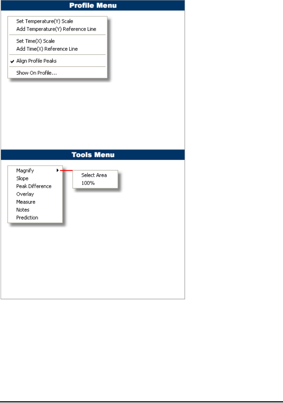
MEGAM.O.L.E.® Help System Guide ♦372♦
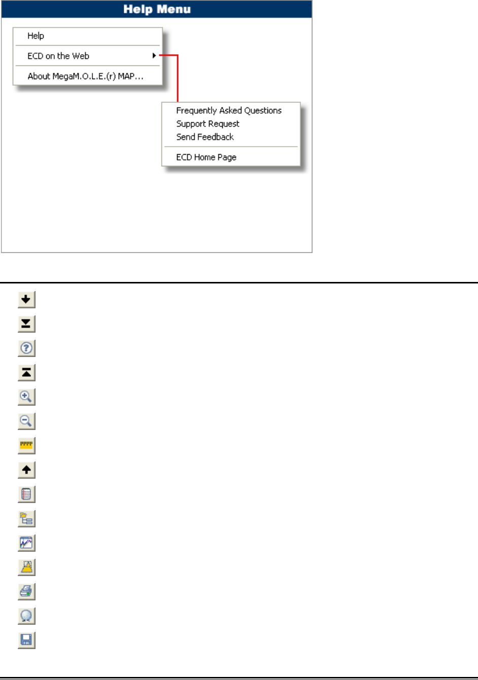
♦373♦ MEGAM.O.L.E.® Help System Guide
Toolbar buttons:
Back (To Previous Data Run)
First (Data Run)
Help
Last (Data Run)
Magnify Window
Magnify 100%
Measure
Next (Data Run)
Notes
Open Working Directory
Overlay
Peak Difference
Print Page Tab
Prediction
Save Data Run

MEGAM.O.L.E.® Help System Guide ♦374♦
Slope
Start/New