Electronic Systems Technology ESTEEM192E User Manual 192E Manual
Electronic Systems Technology 192E Manual
Contents
- 1. User manual
- 2. User Manual
- 3. Revised Manual
User manual

Revision: 1.0 Date: 9 May 01
Electronic Systems Technology (EST) copyrights this manual and the firmware described in it, with all rights reserved. Under
the copyright laws, this manual or the firmware internal to the ESTeem unit may not be copied, in whole or part, without the
written consent of EST. Under the law, copying includes translating into another language.
EST cannot guarantee that you will receive notice of a revision to the firmware described in the manual, even if you have
returned a registration/warranty card received with the product. You should periodically check with your authorized EST
dealer or call factory direct.
EST and the EST logo are registered trademarks of Electronic Systems Technology, Inc. Simultaneously published in the
United States and Canada. All rights reserved.
ESTEEM USERS MANUAL
for
MODEL 192E
May 2001

Revised: 9 May 01
PRODUCT WARRANTY
Electronic Systems Technology, Inc., (hereinafter EST)
expressly warrants its products as free of manufacturing
defects for a period of one year from the date of sale to
first user/customer.
THERE ARE NO OTHER WARRANTIES, EXPRESS
OR IMPLIED AND THERE IS EXPRESSLY
EXCLUDED ALL WARRANTIES OF
MERCHANTABILITY OR FITNESS FOR A
PARTICULAR PURPOSE. NO OTHER WARRANTY
GIVEN BY ANY EMPLOYEE, AGENT,
DISTRIBUTOR OR OTHER PERSON WITH
RESPECT TO THE PRODUCT SHALL BE BINDING
ON EST.
LIMITATION OF LIABILITY:
EST's liability shall be limited to refunding of purchase
price, repair or replacement of product.
IN NO EVENT SHALL EST HAVE LIABILITY FOR
CONSEQUENTIAL, INCIDENTAL, SPECIAL OR
EXEMPLARY DAMAGES CAUSED DIRECTLY OR
INDIRECTLY BY THE PRODUCT, INCLUDING
BUT NOT LIMITED TO ANY INTERRUPTION OF
SERVICES, LOSS OF BUSINESS OR
ANTICIPATORY PROFITS. IN NO EVENT SHALL
EST BE LIABLE FOR ANY DAMAGES
WHATSOEVER IN EXCESS OF THE PURCHASE
PRICE OF THE PRODUCT.
In the event that a unit or part requires replacement or
factory servicing, the following conditions apply:
a) Customer must obtain from EST an authorized
RMA (Return Materials Authorization) number
(call 509-735-9092 Customer Support) before
shipment of product or parts to EST for any
reason;
b) If the whole unit is shipped, it must be in its
original carton and shipping components, or a
carton and shipping components supplied by
EST, or if parts only are shipped, they must be
packaged and cushioned so as to prevent
damage in transit and shipped freight prepaid;
PRODUCT WILL BE CONSIDERED OUT OF
WARRANTY IF:
a) If the product is damaged due to improper or
abnormal use, abuse, mishandling, accident or
improper maintenance or failure to follow
operating instruction;
b) If the product is defective as a result of sand,
dirt, or water damage;
c) If any factory-sealed enclosure has been opened
or shows evidence of an attempt to be opened;
d) If defects or damage are caused by the use of
unauthorized parts or unauthorized service;
e) If the product has had its serial numbers altered
or removed.
Warranty repair form must be accompanied by proof of
user's purchase of unit. Product must be shipped to the
manufacturer at the following address:
Electronic Systems Technology
415 North Quay Street
Kennewick, Washington USA 99336
ADDITIONAL SERVICE:
If EST releases an improvement update to firmware
internal to the ESTeem unit during the 90 day period
after the unit was purchased by the first user/customer,
EST will update the applicable unit with the revised
version at no charge other than for UPS handling and
shipping to and from your location to the EST factory.
Return of any such item must be accompanied with proof
of purchase.

TABLE OF CONTENTS
Revised: 9 May 01
CHAPTER 1 - STARTING OUT
Overview............................................................. 1-2
Hardware Layout .................................................1-2
Installing ESTeem Utility Software –
Windows 95/98/NT .............................................1-2
Running The Program .........................................1-2
Front Panel Description.......................................1-2
Configuration ...................................................... 1-3
Connect and Power Up the ESTeem .................... 1-3
Associate an IP Address with the ESTeem...........1-3
Using a DHCP Server..........................................1-3
Using the arp Command......................................1-3
CHAPTER 2 – APPLICATION
PROGRAMMING
System Configurations.........................................2-2
Access Point Configuration.................................. 2-2
Ethernet Bridge Configuration............................. 2-2
Combined Access Point and Ethernet Bridge.......2-2
CHAPTER 3 - INTERFACING
Serial Interface Configuration.............................. 3-2
RS-232 Port Pin-Out Table.................................. 3-2
Ethernet Interface................................................ 3-3
CHAPTER 4 - ANTENNAS
Antenna and Cable Configurations.......................4-2
Weather Proofing Coaxial Connectors..................4-2
Grounding ...........................................................4-3
Lightning Arrestors..............................................4-3
Model 192E Typical Outdoor Antenna
Installation Diagram ............................................4-3
Model 192E Typical Indoor Antenna
Installation Diagram ............................................4-4
ESTeem SWR Measurements Block Diagram ......4-5
APPENDICES
Appendix A - FCC Licensing
(USA only)................................................ APX A-2
Appendix B - Specifications
ESTeem Specifications................................APX B-1
Model 192E Antenna Specifications............APX B-2
CHAPTER 2
APPLICATION PROGRAMMING
SYSTEM CONFIGURATIONS
ACCESS POINT CONFIGURATION
ETHERNET BRIDGING CONFIGURATION
COMBINED ACCESS POINT AND
ETHERNET BRIDGING CONFIGURATION
Ethernet Wired LAN
Mobile Wireless Network With
Overlap Coverage
192E
Model WLANC11 Wireless
LAN Card
192E
Point to Multi-Point Wireless Network
192E
Ethernet Wired LAN
Wireless Access Point
Programming
Terminal
HMI Terminal
Remote PLC
Remote PLC
192E
192E
Ethernet Wired LAN
LAN Bridging
Digi-Repeating
192E

CHAPTER 2
APPLICATION PROGRAMMING
Revised: 10 May 01 2-3
Ethernet Wired LAN
Mobile Wireless Network
Model WLANC11
Wireless LAN Card
192E
10BASE-T
192E
192E
Ethernet Wired LAN
LAN Bridging
Digi-Repeating
192E
Ethernet Hub
Figure 3: Combination Network

CHAPTER 2
APPLICATION PROGRAMMING
SYSTEM CONFIGURATIONS
ACCESS POINT CONFIGURATION
ETHERNET BRIDGING CONFIGURATION
COMBINED ACCESS POINT AND ETHERNET BRIDGING
CONFIGURATION
CHAPTER 2
APPLICATION PROGRAMMING
Revised: 10 May 01 2-2
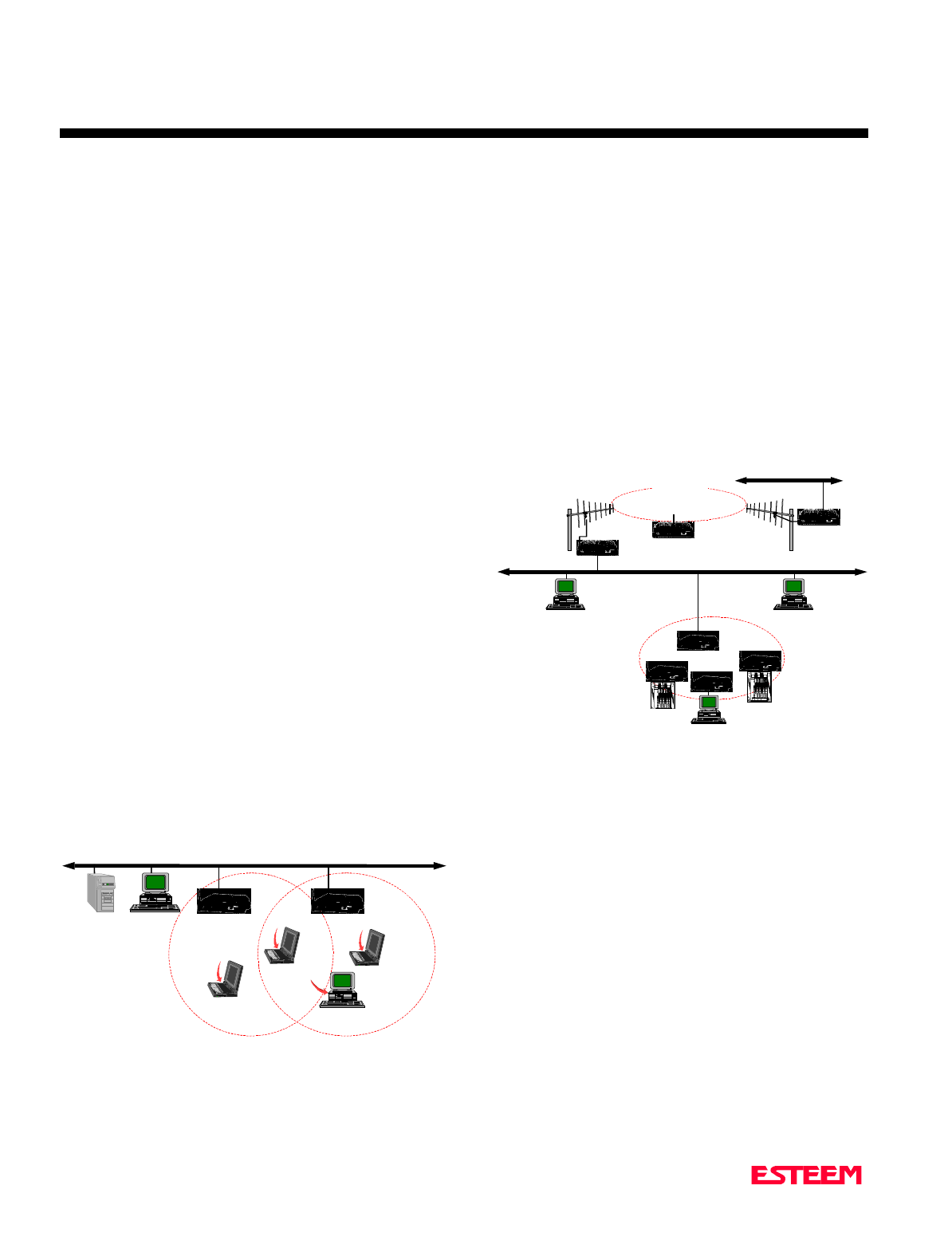
SYSTEM CONFIGURATIONS
The ESTeem Model 192E can be used in a variety of
network system configurations. The ESTeem can stand
alone as the center of a wireless infrastructure, can
provide access from your wireless network to your wired
LAN, or bridge between Ethernet segments on your
network.
The Model 192E can also be configured as a repeater in
the network to increase the range of the wireless
infrastructure. The maximum communications range is
based upon how you configure your wireless network.
This section of the manual will describe the possible
configurations of the wireless network.
ACCESS POINT CONFIGURATION
In this network one of the ESTeem Model 192E modems
is configured as the “Access Point”. This Access Point is
then used to bridge wireless network to the cabled LAN
network or act as the center point on a stand alone
wireless network. When configured in this type of
network, all wireless cards (ESTeem Model WLANC11)
communicate only with the Access Point that serves the
WLAN as a HUB. This type of network can extend the
range of the wireless cards greater than they can directly
communication with each other.
The Access Point is responsible for maintaining a logical
link between the clients and providing the wireless
clients with access to information on the wired LAN
network. Figure 1 shows and example of the Model
192E in an Access Point Configuration.
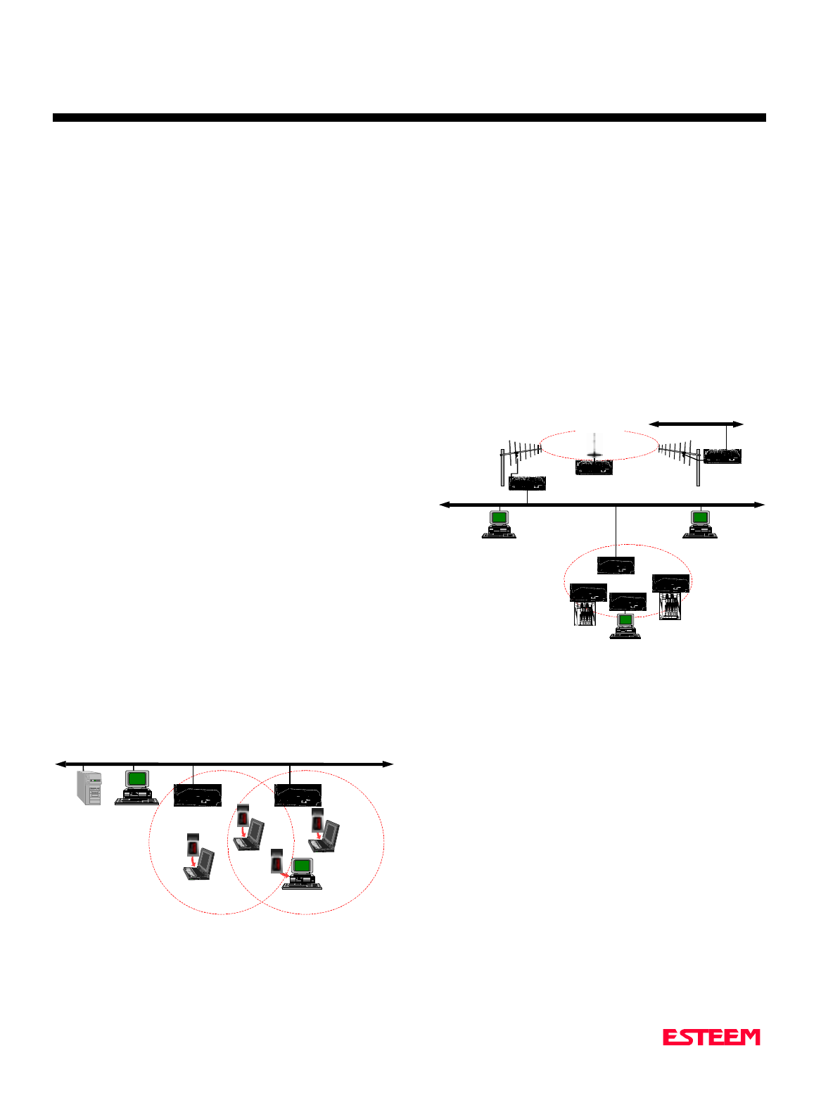
ETHERNET BRIDGING CONFIGURATION
The Ethernet Bridging network allows the Model 192E
modems to provide links between two or more Ethernet
segments on a network. Ethernet segments can be either
single network clients such as computers or PLCs or ties
into building LAN networks such as HUBs or switches.
This type of network can provide tremendous flexibility
in your wireless network configurations and also provide
a much greater range than available through the wireless
card network as described in the Access Point section.
Figure 2 shows an example of an Ethernet Bridging
network.
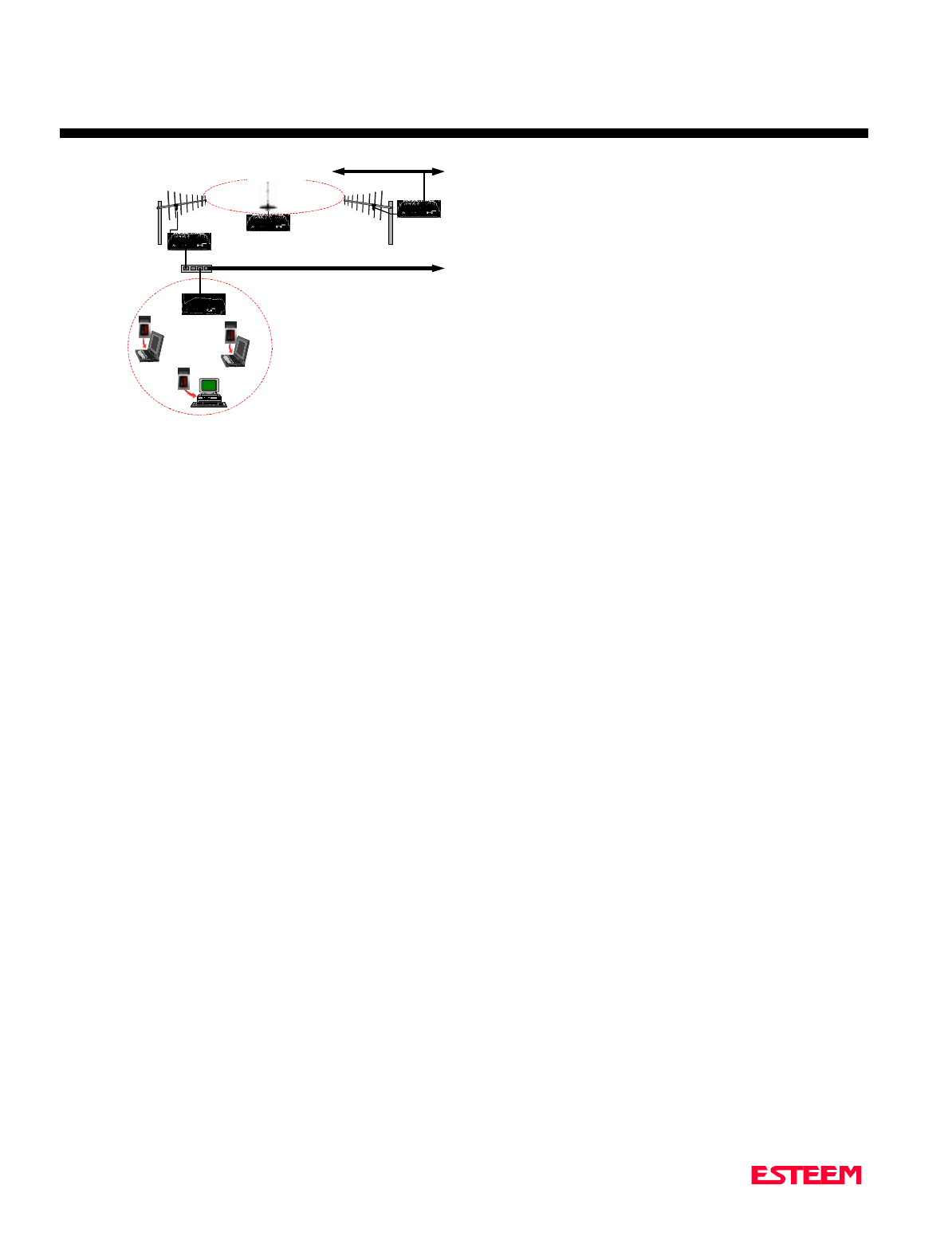
COMBINED ACCESS POINT AND
ETHERNET BRIDGING CONFIGURATION
As the name would imply, this type of network is a
combination of an Access Point network and an Ethernet
Bridging network. This type of network would prove
both communication to a Building LAN network from a
remote Model 192E and also provide wireless access to
the network for the wireless cards. This type of network
requires two ESTeem Model 192E modems and at least a
three port Ethernet HUB. Figure 3 shows a combined
network.
Ethernet Wired LAN
Mobile Wireless Network With
Overlap Coverage
192E
Model WLANC11 Wireless
LAN Card
192E
10BASE-T 10BASE-T
Figure 1: Access Point Network
Point to Multi-Point Wireless Network
10BASE-T
192E
Ethernet Wired LAN
Wireless Access Point
Programming
Terminal
HMI Terminal
Remote PLC
Remote PLC
192E
192E
Ethernet Wired LAN
LAN Bridging
Digi-Repeating
192E
Figure 2: Ethernet Bridging Network
CHAPTER 2
APPLICATION PROGRAMMING
Revised: 10 May 01 2-3
Ethernet Wired LAN
Mobile Wireless Network
Model WLANC11
Wireless LAN Card
192E
10BASE-T
192E
192E
Ethernet Wired LAN
LAN Bridging
Digi-Repeating
192E
Ethernet Hub
Figure 3: Combination Network

CHAPTER 3
INTERFACING
SERIAL INTERFACE CONFIGURATION
RS-232 PORT PINOUT TABLE
ETHERNET INTERFACE

CHAPTER 3
INTERFACING
Revised: 10 May 01 3-2
SERIAL INTERFACE CONFIGURATION
The ESTeem Model 192E has a standard RS-232C, 9-pin
Female connector for interfacing directly with the serial
port on the computer. Use ESTeem part number AA062
to interface the Model 192E with a 9-pin serial port on a
computer.
The serial port on the ESTeem Model 192E can be used
to access the configuration menu in the ESTeem for
system and network configuration. The ESTeem
communications port operates at 19,200 bps, No Parity, 8
Data Bits and 1 Stop Bit (19,200,N,8,1). Configure your
terminal program to match these settings.
RS-232 PORT PIN-OUT TABLE
ESTeem Model 192E
RS-232C Port Pin-Out Table
Pin No. Function
1Data Carrier Detect (DCD)
2Receive Data (RxD)
3Transmit Data (TxD)
4Data Terminal Ready (DTR)
5Signal Ground
6Data Set Ready (DSR)
7Request To Send (RTS Input)
8Clear To Send (CTS)
9Ring Line (RI)
ETHERNET INTERFACE
The ESTeem Model 192E’s Ethernet Port is configured
to directly interface with an Ethernet HUB using a
straight through 10BaseT cable. If the ESTeem is
connected to a network interface card (NIC), you will
need to use 10BaseT reversing cable.

CHAPTER 4
ANTENNAS
ANTENNA AND CABLE CONFIGURATIONS
WEATHER PROOFING COAXIAL CONNECTORS
GROUNDING
LIGHTINING ARRESTORS
MODEL 192E TYPICAL OUTDOOR ANTENNA
INSTALLATION DIAGRAM
MODEL 192E TYPICAL INDOOR ANTENNA INSTALLATION
DIAGRAMS
ESTEEM SWR MEASUREMENT BLOCK DIAGRAM

CHAPTER 4
ANTENNAS
Revised: 10 May 01 4-2
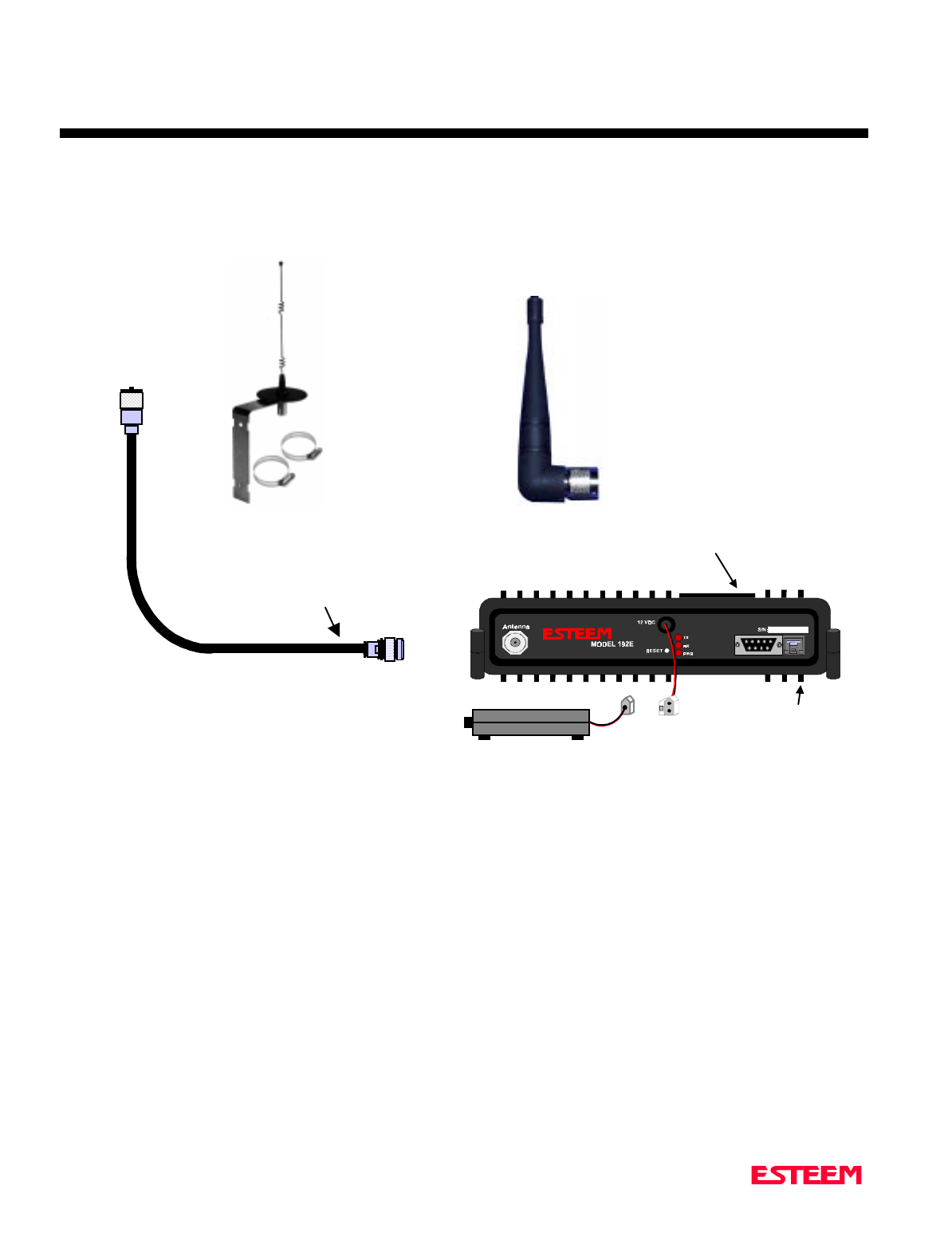
ANTENNA AND CABLE
CONFIGURATIONS
EST offers three (3) different types of antennas for both
indoor and outdoor configurations.
Part Number: AA01S
Omni Directional Rubber Duck Antenna.
Unity Gain
Part Number: AA20S
Omni Directional Building Mount Antenna
5 dB gain
Part Number: AA202S
Directional Building Mount Antenna
13.9 dB gain
Outdoor Fixed Base Configuration
Lightning Protection
50’ Heliax Cable
Indoor Configuration
25’ RG-8 Cable
Note: The cables and antennas are optimized with the
ESTeem for maximum output power allowed by
the FCC and IC.
Extreme care must be taken when attaching
coax connectors to the antenna feedlines.
If there is any error in making this
connection the output of the transmitter will
be greatly reduced.
COAXIAL CABLES
To minimize signal loss, the overall length of the coaxial
cable should be as short as possible. To avoid corrosion
select coaxial cable manufacturers with tinned copper
braid, where possible. Listed below are representative
cable losses in db/100 ft at the 2.4 GHz frequency range:
Frequency (GHz) RG-8 ½” Heliax
---------------------------------------------------------------------
2.400-2.462 - 8.0 - 3.74
In a severe noise environment it may be desirable to use a
double shield type of coax cable such as RG-214/U in
place of the RG-8.
Note: Pre-made coax cables can be purchased from
the factory. A -3 dB loss means you have lost
1/2 of your signal. A +3 dB gain means you
have doubled (x2) your signal.
WEATHER PROOFING COAX
CONNECTIONS
1. Coat the threads of the connectors with silicone
lubricant prior to assembly (See Note 1) and hand
tighten. Care should be taken not to get any
lubricant on the center conductor.
2. Wrap the connector assembly with a vapor barrier
patch for weather proofing (See Note 2), ensuring to
overlap onto the coax cable approximately 1 1/2
inches.
3. Apply an electrical coating (sealing agent) over the
vapor barrier patch for added protection (See Note
3).
Notes:
1. Dow Corning RTV-3140 or equivalent.
2. Suggested vendors:
VAPOR-WRAP
Decibel Products
3184 Quebec St.
Dallas, TX 75356
214-631-0310

CHAPTER 4
ANTENNAS
Revised: 10 May 01 4-3
VYNIL-MASTIC, P/N 2200
3-M Company
Customer Service
512-984-1800
3. SCOTCHKOTE, 3-M Company, or equivalent.
GROUNDING
All building mount antennas require attachment to a
good earth ground for optimum efficiency. Contact a
reputable local communications shop for procedures for
your area.
LIGHTNING ARRESTORS
Lightning arrestors should be used on all external
building mount antennas for personal protection and to
minimize damage to the transceiver during lightning
storms. The units should be installed as per
manufacturers instructions provided with the device.
CHAPTER 4
ANTENNAS
Revised: 10 May 01 4-4
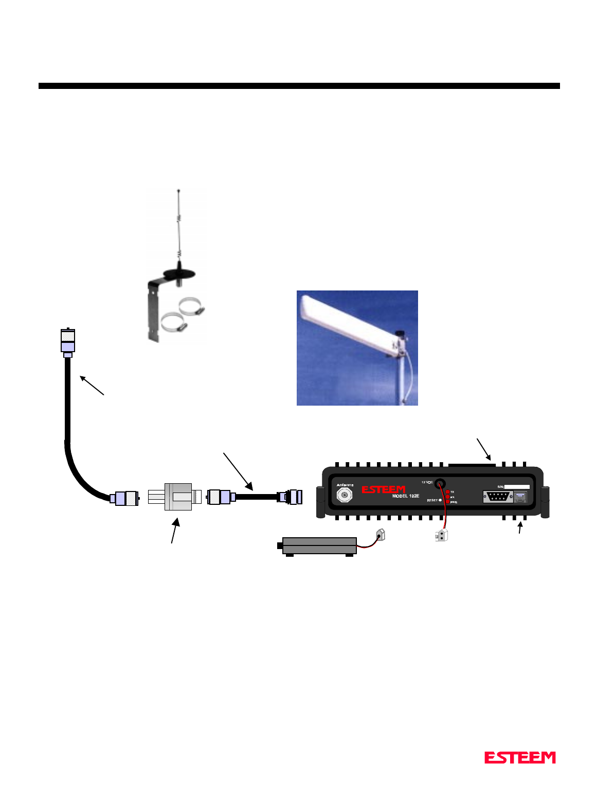
Model 192E
Outdoor Fixed Base Site Diagram
ANTENNA
RECOMMENDATIONS
N Male
Connector
Heliax Feedline
EST P/N AA236, 50 ft.
N Male
Connector
N Male
Connector
TNC-R
Male Connector
LIGHTNING
ARRESTOR
EST P/N AA164 12 VDC POWER SUPPLY
RECOMMENDATIONS
EST P/N AA174
Battery Packs
Solar Power
2 Pin Molex
Connector
RG-8 Coax
EST P/N AA230, 2 ft.
RS-232 Interface
Connector
Omni-Directional
Antenna
EST P/N AA20S.
Warning
Omni-
directional
antenna should
not be located
within 20 cm of
personnel.
Directional Antenna
EST P/N AA202S.
Warning
High gain
directional
antenna’s main
beam should not
be pointed in
close proximity of
personnel.
RJ-45 Ethernet
Connector
CHAPTER 4
ANTENNAS
Revised: 10 May 01 4-5
Model 192E Indoor Equipment Diagram
RE
SET
N Male
Connector
TNC-R
Male Connector
12 VDC POWER SUPPLY
RECOMMENDATIONS
EST P/N AA174
Batter
y
Packs
Solar Power
2 Pin Molex
Connector
RG-8 Coax
EST P/N AA230, 25 ft.
RE
SET
Omni-Directional
Antenna
EST P/N AA01S.
Rubber duck, back
of set mount
RS-232 Interface
Connector
RJ-45 Ethernet
Connector
Warning
Omni-
directional
antenna
should not be
located within
20 cm of
personnel.
Omni-Directional
Antenna
EST P/N AA20S.
CHAPTER 4
ANTENNAS
Revised: 10 May 01 4-6
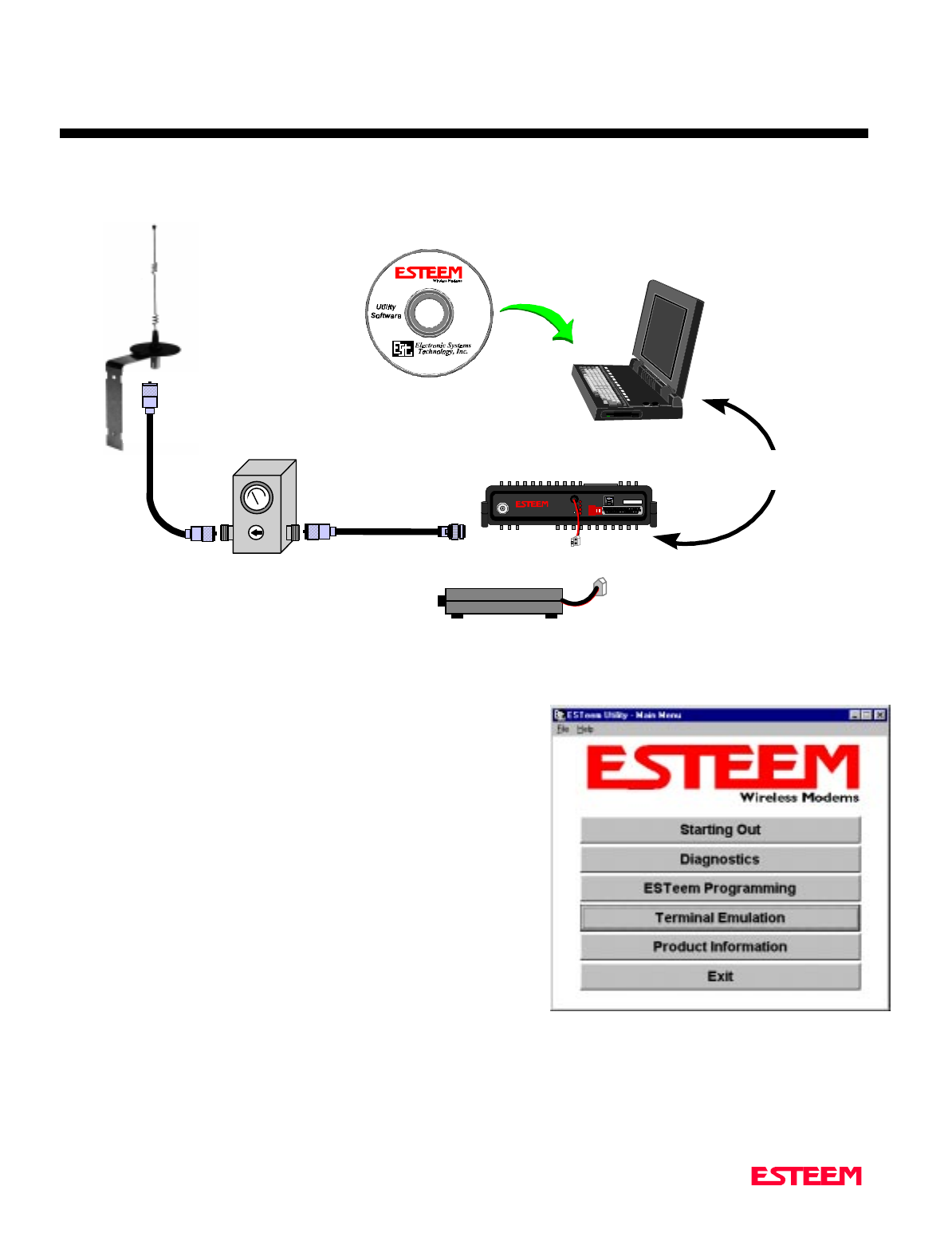
ESTeem SWR Measurement Block Diagram
Programming the ESTeem Model 192E For SWR Measurements
1. Configure the hardware as per the above diagram.
2. Install the ESTeem Utility on the PC hard drive as per instructions
with the software.
3. From Utility Main Menu (Figure 1) select the Terminal Emulation
Mode.
4. In the Terminal Emulation Mode press the Enter key to display the
Model 192E configuration menu.
5. Select the Turn Transmitter ON option.
6. When the testing is completed, select Turn Transmitter OFF option
on the configuration menu.
Figure 1: ESTeem Utility Main Menu
N Male
Connector N Male
Connector
TNC-R Male
Connector
Antenna
2 Pin Molex
Connector
RS-232C Interface Cable
(EST P/N AA062)
N Male
Connector
SWR Meter
RG-8 Cable
(EST P/N AA230)
12 VDC Power Supply
(EST P/N AA174)
S/ N:T/E
TX
RX
PW R
IR
Po rt
Phone
Model 192S
Antenna 12 V D C
RESET
ESTeem Model 192 Utility
Software Windows Version
Warning
Omni-directional antenna
should not be located within
20 cm of personnel
High gain directional
antenna’s main beam should
not be pointed in close
proximity of personnel.

APPENDICES
APPENDIX “A” FCC INFORMATION (USA Only)
APPENDIX “B” SPECIFICATIONS
ESTeem Specifications
Antenna Specifications

APPENDIX A
FCC LICENSING
Revised: 11 May 01 APX A-2
INFORMATION TO USERS
This equipment complies with FCC Part 15.
Other Information
Model 192E
Direct Sequence
FCC Type Acceptance No: ENPESTEEM192E

APPENDIX A
FCC LICENSING
Revised: 11 May 01 APX A-3
FEDERAL COMMUNICATIONS COMMISSION FIELD OFFICES
ALASKA
1011 E. Tudor Rd.
Rm 240 Box 2955
Anchorage, AK 99510
CALIFORNIA
7840 El Cajon Blvd
Suite 405
La Mesa, CA 92041
3711 Long Beach Blvd
Suite 501
Long Beach, CA 90807
323A Battery St
San Francisco, CA 94111
COLORADO
Executive Tower
1405 Curtis St
Suite 2925
Denver, CO 80202
FLORIDA
919 Federal Bldg
51 SE First Ave.
Miami, FL 33130
1211 N. Westshore
Suite 601
A.D. P. Building
Tampa, FL 33607
GEORGIA
Massell Bldg. 440
1365 Peachtree NE
Atlanta, GA 30309
HAWAII
7304 Prince Kuhi
Federal Building
Honolulu, HI
HAWAII
300 Almoana Blvd.
P.O. Box 50023
Honolulu, HI
ILLINOIS
3935 Federal Bldg
230 S. Dearborn
Chicago, IL 60604
LOUISIANA
1009 Edw Hebert Bldg.
600 South Street
New Orleans, LA 70130
MARYLAND
1017 Geo. Fallon
Building 31
Hopkins Plaza
Baltimore, MD
MASSACHUSETTS
1600 Customhouse
165 State Street
Boston, MA 02109
MICHIGAN
1054 Federal Building
231 W LaFayette
Detroit, MI 48225
MINNESOTA
691 Federal Building
316 N Robert St.
St. Paul, MN
MISSOURI
Brywood Office Tower
6800 E. 63rd Street
Kansas City, MO
NEW YORK
1307 Federal Building
111 W. Huron
Buffalo, NY 14202
201 Varick Street
New York, NY 10014
OREGON
1782 Federal Building
1220 SW 3rd Avenue
Portland, OR 97204
PENNSYLVANIA
Room 404
2300 E. Lincoln H
Langhorne, PA
PUERTO RICO
747 Federal Building
Carlo Chardon Ave.
Hato Rey, PR 00918
TEXAS
Cabeli Building
1100 Commerce
Dallas, TX 75242
5636 Federal Building
515 Rusk Avenue
Houston, TX 77002
VIRGINIA
Military Circle
870 N. Military Hwy.
Norfolk, VA 23502
WASHINGTON
3256 Federal Building
915 Second Avenue
Seattle, WA 98174

APPENDIX B
SPECIFICATIONS
Model 192E Specifications
Revised: 11 May 01 APX B-1
LED INDICATORS
• Power On
• Receiver Carrier Detect
• Transmitter Enable
I/O – CONNECTORS
• RS-232C - 9 Pin Sub D Female
• RJ-45 10BaseT Connection
• Antenna Output – TNC-R
• Input Power - 2 Pin Molex
Female
DATA INPUT
• RS-232 Asynchronous
• 19,200 baud Fixed Data Rate
• 8 data bits
• No parity
• One Stop Bit
FREQUENCY OF
OPERATION
• 2.4 to 2.462 GHz.
• Frequency selectable in 11
frequency zones
RF DATA RATE
• 1-11 Mbps RF data rate
TRANSMITTER
• 1 Watt RF output
• 100% duty cycle
• 50 ohms output impedance
• Protocol activated keying
• 10 µsec typical latency
• Direct sequence spread spectrum
RECEIVER
• Double conversion
superheterodyne
• -93 dBm 8E-2 Frame Error Rate
• 80 dB Image Rejection
• > 35 dBm Adjacent Channel
Rejection
POWER REQUIREMENTS
• 11-16 VDC @ 700 ma Transmit
300 ma Receive
SIZE
• 2.45 in. Height
8.16 in. Width
9.37 in. Length
WEIGHT:
• 4.6 lbs.
• Rugged die cast aluminum case
ENVIRONMENT
• -30° to 50° C
• 95% Non-condensing
WARRANTY
1 Year
APPENDIX B
SPECIFICATIONS
Model 192S Antennas
Revised: 11 May 01 APX B-2
Model No: AA01S
Antenna Type: Omni-Directional, right angle rubber duck, ½ wave
Applications:Back of ESTeem Model 192S mount.
Frequency: 2400 to 2485 MHz
Polarization: Vertical
Impedance: 50 ohms
Gain: 3 dBd
VSWR: < 1.5
Front To Back Ratio: n/a
Horizontal Beamwidth: n/a
Vertical Beamwidth: n/a
Antenna Material: Rubber duct whip.
Mounting Hardware: n/a
Antenna Connector:TNC-R Male
Antenna Envelope: 4 in. length by 1.5 in width
Weight: .08 lbs.
Model No: AA20S
Antenna Type: Omni Directional, 5/8 Wave over 5/8 Wave over ¼ Wave.
Applications:Fixed base or mobile mount.
Frequency: 2400 to 2485 MHz
Polarization: Vertical
Impedance: 50 ohms
Gain: 5 dBd
VSWR: < 1.5
Front To Back Ratio: n/a
Horizontal Beamwidth: n/a
Vertical Beamwidth: n/a
Antenna Material: Stainless steel whip. All other hardware anodized metal.
Mounting Hardware: Stainless steel clamps for mounting to ¾ in. to 1½ in. pipe
with right angle mount of direct panel mount..
Antenna Connector:N Female.
Antenna Envelope: 9 in. length by 3.5 in. width
Weight: .4 lbs.
3.5 in. Dia.
Right Angle
Mounting
Bracket
Stanless
Steel
Clamps
9 in.
Model AA20S
4 in.
1.5 in.
Model AA01S
Warning
Omni-directional antenna
should not be located
within 20 cm of personnel

APPENDIX B
SPECIFICATIONS
Model 192S Antennas
Revised: 11 May 01 APX B-3
Model No: AA202S
Antenna Type: Directional, 15 element yagi in sealed UV
stable radome
Applications:Fixed base.
Frequency: 2400 to 2500 MHz
Polarization: Linear
Impedance: 50 ohms
Gain: 13.9 dBd
VSWR: < 1.5
Front To Back Ratio: 18 dB
Horizontal Beamwidth: 34 degrees
Vertical Beamwidth: 30 degrees
Antenna Material: Stainless hardware with one piece copper
radiating element. Advanced microwave
substrate. All other hardware anodized
metal.
Mounting Hardware: Stainless steel U bolts for mounting to 1.5
in. to 2.2 in. diameter pipe.
Antenna Connector:N Female on UltraLink® Pigtail
Maximum Power Input: 50 Watts
Antenna Envelope: 26 in. length by 4.0 in. height by 1.5 in. width
Windload (RWV): 125 mph
Wind Load ½ in. Ice: 100 mph
Wind Surface Area: 0.4 ft2
Weight: 1.25 lbs.
Model AA202S
Warning
High gain directional antenna’s
main beam should not be
pointed in close proximity of
personnel.