Electronic Systems Technology ESTEEM192E User Manual 192E Manual
Electronic Systems Technology 192E Manual
Contents
- 1. User manual
- 2. User Manual
- 3. Revised Manual
Revised Manual
Revision: 1.1 Date: 15 Oct 01
Electronic Systems Technology (EST) copyrights this manual and the firmware described in it, with all rights reserved. Under
the copyright laws, this manual or the firmware internal to the ESTeem unit may not be copied, in whole or part, without the
written consent of EST. Under the law, copying includes translating into another language.
EST cannot guarantee that you will receive notice of a revision to the firmware described in the manual, even if you have
returned a registration/warranty card received with the product. You should periodically check with your authorized EST
dealer or call factory direct.
EST and the EST logo are registered trademarks of Electronic Systems Technology, Inc. Simultaneously published in the
United States and Canada. All rights reserved.
ESTEEM USERS MANUAL
for
MODEL 192E
October 2001

Revised: 15 Oct 01
PRODUCT WARRANTY
Electronic Systems Technology, Inc., (hereinafter EST)
expressly warrants its products as free of manufacturing
defects for a period of one year from the date of sale to
first user/customer.
THERE ARE NO OTHER WARRANTIES, EXPRESS
OR IMPLIED AND THERE IS EXPRESSLY
EXCLUDED ALL WARRANTIES OF
MERCHANTABILITY OR FITNESS FOR A
PARTICULAR PURPOSE. NO OTHER WARRANTY
GIVEN BY ANY EMPLOYEE, AGENT,
DISTRIBUTOR OR OTHER PERSON WITH
RESPECT TO THE PRODUCT SHALL BE BINDING
ON EST.
LIMITATION OF LIABILITY:
EST's liability shall be limited to refunding of purchase
price, repair or replacement of product.
IN NO EVENT SHALL EST HAVE LIABILITY FOR
CONSEQUENTIAL, INCIDENTAL, SPECIAL OR
EXEMPLARY DAMAGES CAUSED DIRECTLY OR
INDIRECTLY BY THE PRODUCT, INCLUDING
BUT NOT LIMITED TO ANY INTERRUPTION OF
SERVICES, LOSS OF BUSINESS OR
ANTICIPATORY PROFITS. IN NO EVENT SHALL
EST BE LIABLE FOR ANY DAMAGES
WHATSOEVER IN EXCESS OF THE PURCHASE
PRICE OF THE PRODUCT.
In the event that a unit or part requires replacement or
factory servicing, the following conditions apply:
a) Customer must obtain from EST an authorized
RMA (Return Materials Authorization) number
(call 509-735-9092 Customer Support) before
shipment of product or parts to EST for any
reason;
b) If the whole unit is shipped, it must be in its
original carton and shipping components, or a
carton and shipping components supplied by
EST, or if parts only are shipped, they must be
packaged and cushioned so as to prevent
damage in transit and shipped freight prepaid;
PRODUCT WILL BE CONSIDERED OUT OF
WARRANTY IF:
a) If the product is damaged due to improper or
abnormal use, abuse, mishandling, accident or
improper maintenance or failure to follow
operating instruction;
b) If the product is defective as a result of sand,
dirt, or water damage;
c) If any factory-sealed enclosure has been opened
or shows evidence of an attempt to be opened;
d) If defects or damage are caused by the use of
unauthorized parts or unauthorized service;
e) If the product has had its serial numbers altered
or removed.
Warranty repair form must be accompanied by proof of
user's purchase of unit. Product must be shipped to the
manufacturer at the following address:
Electronic Systems Technology
415 North Quay Street
Kennewick, Washington USA 99336
ADDITIONAL SERVICE:
If EST releases an improvement update to firmware
internal to the ESTeem unit during the 90 day period
after the unit was purchased by the first user/customer,
EST will update the applicable unit with the revised
version at no charge other than for UPS handling and
shipping to and from your location to the EST factory.
Return of any such item must be accompanied with proof
of purchase.

TABLE OF CONTENTS
Revised: 15 Oct 01
CHAPTER 1 - STARTING OUT
Overview .............................................................1-2
Hardware Layout .................................................1-2
Installing ESTeem Utility Software –
Windows 95/98/NT..............................................1-2
Running The Program .........................................1-2
Front Panel Description .......................................1-3
Basic Configuration.............................................1-3
Connect and Power Up the ESTeem.....................1-3
Opening the ESTeem Configuration Menu ..........1-4
CHAPTER 2 – APPLICATION
PROGRAMMING
Selecting Ethernet Configuration.........................2-2
Using the Configuration Menu.............................2-2
Accessing Through Telnet ...................................2-2
Changing Configuration Information...................2-2
Saving and Exiting Configuration Menu..............2-2
Modem Setup.......................................................2-2
Step 1 – Radio Configuration...............................2-2
Step 2 – Modes of Operation................................2-3
Access Point Configuration..................................2-3
Ethernet Bridging Configuration .........................2-4
Master Bridge......................................................2-5
Client Bridge.......................................................2-5
Repeater Configuration ....................................... 2-6
Combined Access Point and Bridging.................. 2-6
Loading Factory Default Values .......................... 2-7
CHAPTER 3 - INTERFACING
Serial Interface Configuration ............................. 3-2
RS-232 Port Pin-Out Table.................................. 3-2
Ethernet Interface................................................ 3-3
CHAPTER 4 - ANTENNAS
Antenna and Cable Configurations...................... 4-2
Weather Proofing Coaxial Connectors................. 4-2
Grounding........................................................... 4-3
Lightning Arrestors............................................. 4-3
Model 192E Typical Outdoor Antenna
Installation Diagram ........................................... 4-3
Model 192E Typical Indoor Antenna
Installation Diagram ........................................... 4-4
ESTeem SWR Measurements Block Diagram ..... 4-5
APPENDICES
Appendix A - FCC Licensing
(USA only)................................................ APX A-2
Appendix B - Specifications
ESTeem Specifications............................... APX B-1
Model 192E Antenna Specifications........... APX B-2

CHAPTER 1
STARTING OUT
OVERVIEW
HARDWARE LAYOUT
INSTALLING SOFTWARE
Installing ESTeem Utility Software
Running The Program
FRONT PANEL DESCRIPTION
BASIC CONFIGURATION
Connect and Power Up the ESTeem
Opening the Configuration Menu

CHAPTER 1
STARTING OUT
Revised: 2 Oct 01 1-2
OVERVIEW
The ESTeem Model 192E is a wireless LAN transceiver
that can be configured as the center point of a stand-
alone wireless network, connection point between
wireless and wired network (Access Point) or a bridge
between Ethernet segments. Each configuration is
explained in detail in Chapter 2 of this manual. This
section of the User’s Manual will complete the basic
configuration of the system and allow further
programming through the ESTeem Configuration Menu.
The ESTeem Model 192E uses a menu-driven
management system for configuration and diagnostics.
This management system can be accessed through a
Telnet network connection or through any terminal
emulation program. To link through the network
connection, some of the basic operating parameters such
as assigning the ESTeem an IP address and Subnet mask
must be completed by accessing the configuration menu
through the serial port. Any terminal emulation program
can be used for this configuration of the ESTeem and
will be configured similarly, but this section of the
manual will describe basic configuration of the ESTeem
Model 192E using the Terminal Emulation program
contained on the ESTeem Utility Program CD-ROM.
HARDWARE LAYOUT
Locate the items contained in Figure 1 for initial
configuration of the ESTeem Model 192E. Take a few
minutes to inventory your equipment before you proceed.
Report any missing or damaged items to Customer
Support (509-735-9092) as soon as possible.
Caution: Your ESTeem hardware may have antennas
other than the AA01S listed in Figure 1, but you must
have an antenna connected to the antenna port before
applying power to the unit.
INSTALLING SOFTWARE
The ESTeem Utility Program is designed to provide the
ESTeem user access to the configuration menu of the
ESTeem Model 192E. The Utility contains a Terminal
Emulation program that will allow direct access to the
management menus of the modem. None of the other
sections of this utility, such as Diagnostics will function
with the Model 192E. The ESTeem Utility Program is
designed to operate with Windows 95®, Windows 98®
and Windows NT® 4.0 and greater.
Installing ESTeem Utility Software
Windows 95/98/NT4.0 (or greater)
1. Place the ESTeem Utility Software CD in your CD-
ROM drive (Figure 1).
2. Select Run on the Start Menu.
3. Type (your CD-ROM drive letter, D in this example
D:\ESTUtil\Setup.exe)
4. Click the OK button and the program will begin
installation.
Running The Program
1. Select the ESTeem Utility Icon on Start>Programs
menu. Figure 2 shows an example of the Main
Utility Menu.
Figure 2: ESTeem Utility Main Menu
RS-232C Interface Cable
(EST P/N AA062)
12 VDC Power Supply
(EST P/N AA174)
2 Pin Molex
Connector
ESTeem Model 192E
Rear View
ESTeem Model 192 Utility
Software Windows Version
(EST P/N AA107)
Computer Running
Windows 95/98/NT
Rubber Duck Antenna
(EST P/N AA01S)
Warning
Omni-directional antenna
should not be located within
7cm of personnel
Figure 1: Hardware Layout Diagram
CHAPTER 1
STARTING OUT
Revised: 2 Oct 01 1-3
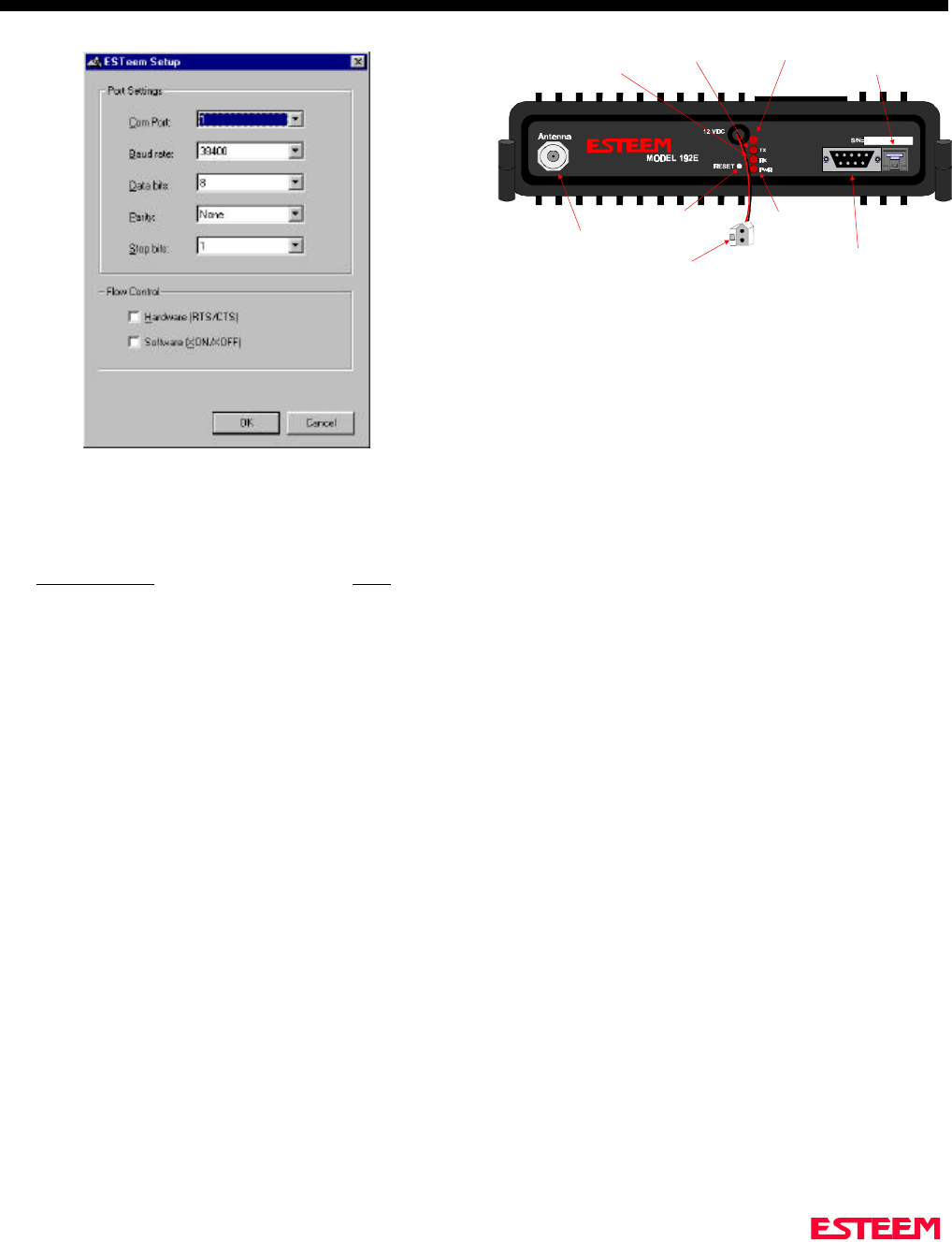
2. Select Terminal Emulation from the Main Menu.
3. Once the Terminal Emulation is loaded, select the
Terminal Setup from the menu and press Ports. You
should see the serial port configuration menu (Figure
3).
4. Select the serial port you have connected to the
ESTeem Model 192E (i.e. COM1 would be 1), set
the Baud Rate to 38400, Data Bits to 8, Parity to
None, Stop Bits to 1 and leave both the Hardware
and Software flow control boxes unchecked. Press
the OK button when complete.
5. Verify the settings in the upper left hand corner of
the Terminal window are set to
COM1:38400,N,8,1). If the communications port
number is other than 1 it will be displayed as the
number (i.e. COM2, etc.).
The software is now configured for accessing the
ESTeem Model 192E for system configuration. Any
other terminal emulation program will need to be
configured similarly.
FRONT PANEL DESCRIPTION
Figure 4 contains a description of the ESTeem Model
192E front panel.
BASIC CONFIGURATION
Connect and Power Up the ESTeem
The following steps should be completed before any
modifications are made to the network operating
parameters for the ESTeem Model 192E.
Note: Plan to configure the Model 192E prior to
mounting. Some of the following steps, such as
connecting the serial cable, are easier to perform if the
ESTeem is accessible.
1. Connect the antenna to the antenna port on the
ESTeem Model 192E (Figure 4).
2. Connect the Ethernet cable from the wired 10BaseT
Ethernet LAN to the Ethernet connector on the front
of the ESTeem (Figure 4).
3. Connect the serial cable (EST P/N: AA062) between
the RS-232 connector on the ESTeem to the serial
port on the computer.
4. Plug the ESTeem Model AA174 power supply into a
wall socket and connect the Molex power connector
to the ESTeem. The power light (PWR) on the front
of the ESTeem should be illuminated.
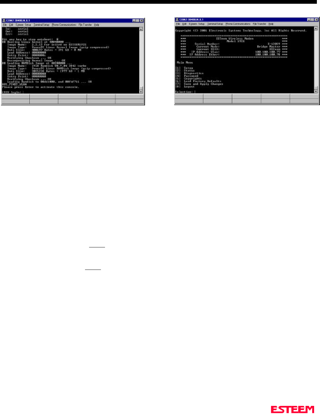
5. You should see the ESTeem Model 192E booting
sequence on your Terminal Emulation program.
Once the ESTeem boot sequence is complete
(approximately 1 minute) you will receive the
message “Please press Enter to active this console.”
6. Press the Enter key and you will be at the
Configuration Menu login prompt (192E login:).
See Figure 5 for an example of this prompt.
Figure 3: Serial Port Configuration Menu
Antenna Connector
(TNC-R)
12 VDC Input
Power Connector
(2 Pin Molex)
Reset Switch
RS-232
Input/Output Connector
(9 Pin DB Connector)
RJ-45 10BaseT
Ethernet Port
Power LED
Transmit LED
Receive LED
T/E LED
T/E
Figure 4: Front Panel Description
CHAPTER 1
STARTING OUT
Revised: 2 Oct 01 1-4
Opening the ESTeem Configuration Menu
To enter the Model 192E Configuration Menu you will
need to log into the system with a login name and
password.
Note: These values can be changed from factory default
through the Configuration Menu. If this not the first time
configuration of the ESTeem, see you network systems
administrator for these values.
If this is the first time the ESTeem has been programmed
or the login was not changed from the factory default
values, please use the following to access the
Configuration Menu:
1. At the 192E login prompt type admin for the login
name and press the Enter key (<Enter>). Please note
that all characters are lower case.
2. At the Password prompt type admin for the password
and press the Enter key (<Enter>). Please note that
all characters are lower case.
The ESTeem Configuration Menu (Figure 6) will now be
displayed. Please proceed to Chapter 2 in this manual for
programming the ESTeem Model 192E for your specific
application.
Figure 5: Boot Prompt Example Figure 6: Configuration Menu

CHAPTER 2
APPLICATION PROGRAMMING
SELECTING ETHERNET CONFIGURATION
USING THE CONFIGURATION MENU
Accessing Through Telnet
Changing Configuration Information
Saving and Exiting Configuration Menu
MODEM SETUP
Step 1 - Radio Configuration
Step 2 – Modes of Operation
Access Point Configuration
Ethernet Bridging Configuration
Repeater Configuration
Combined Access Point and Ethernet Bridging
LOADING FACTORY DEFAULT VALUES
CHAPTER 2
APPLICATION PROGRAMMING
Revised: 2 Oct 01 2-2
SELECTING ETHERNET
CONFIGURATION
To begin setup of your wireless Ethernet network you
must first select the type of Model 192E configuration
required. The following are examples of networking
requirements and the type of configuration required for
each:
Networking Requirements Model 192E
Configuration
Link 802.11b wireless network cards
(EST P/N: WLANC11 or others) in
Infrastructure Mode
Access Point
(Figure 3)
Provide relay point for wireless
network cards (EST P/N: WLANC11
or others) to increase range of Wireless
Area Network (WLAN)
Access Point
Provide access to a cabled Ethernet
network from a wireless network
(WLAN)
Access Point
Communicate between two or more
Ethernet (10BaseT) ports using the
Model 192E
Ethernet
Bridge
(Figure 6)
Link two or more Ethernet HUBs using
the Model 192E Ethernet
Bridge
Provide building to building Ethernet
access using Model 192E Ethernet
Bridge
Provide wireless Ethernet links to both
remote 10BaseT Ethernet ports and
access to wireless network cards
Combined
Access Point
and Bridge
(Figure 10)
All possible Ethernet network configurations can not be
listed. If your application does not match any of the
above Networking Requirements, please consult with
your network system administrator or contact EST
Customer Support at 509-735-9092.
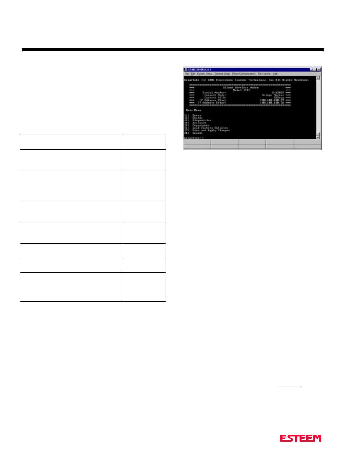
USING THE CONFIGURATION MENU
The ESTeem Model 192E Configuration Menu (Figure
1) is used to set the operating parameters of the wireless
Ethernet modem to operate in an Ethernet network. We
learned in Chapter 1- Starting Out how to configure a
terminal emulation program to access the Configuration
Menu through the RS-232 port on the ESTeem. If you
have not completed Chapter 1 or have questions on how
to access the Configuration Menu, please review that
section before proceeding.
Accessing Through Telnet
Looking at the Main Menu screen of the Configuration
Menu, you will notice the header lists the connected
ESTeem Model 192E’s serial number, current mode of
operation, current Service Set Identifier (SSID - if Access
Point) or Bridge IP address (Bridge Mode Only), and IP
address. Using the IP address, you can start a Telnet
session to the ESTeem through the Ethernet network to
access the Configuration Menu.
Note: If the ESTeem Model 192E is configured in
Ethernet Bridge mode, the Wireless IP and the Ethernet
IP addresses must be on unique Subnets (See Ethernet
Bridging Configuration for more information) to gain
access to the configuration menu through Telnet. Each
operating system has a different method of starting a
Telnet session. Please review the documentation on your
operating system or consult with your network system
administrator.
Changing Configuration Information
To move between menu items in the ESTeem Model
192E Configuration Menu you must first enter the
number next to the menu item and then press the Enter
Key (<Enter>). All commands must be followed by the
Enter key. For example, to review the Copyright
information on the ESTeem Model 192E, press the
number 5 key followed by the Enter key (5<Enter>).
The Configuration Menu will always prompt you if
further input is required or the input received was
invalid. To back out of most menu screens and return to
Figure 1: Configuration Menu

CHAPTER 2
APPLICATION PROGRAMMING
Revised: 2 Oct 01 2-3
the previous menu without making changes, press the X
key followed by the Enter key (X<Enter).
Saving and Exiting Configuration Menu
Any changes made in the Configuration Menu will
only take effect in the Model 192E when the Save and
Apply Changes (7<Enter>) is selected. When Save and
Apply Changes is selected, you will be asked if you wish
to continue. Press the Y key followed by the Enter key
(Y<Enter>) and the ESTeem will save the changes and
reboot the modem. It will take approximately 1 minute
for the ESTeem to reboot to obtain a new login prompt.
If you wish to exit the Configuration Menu without
saving any of the changes made, select Logout
(8<Enter>).
Note: Any changes made during the time you were
logged into the Configuration Menu will be lost.
MODEM SETUP
Step 1 – Radio Configuration
The first step in configuring a wireless Ethernet network
is setting all ESTeem Model 192Es that communicate
with each other to the same radio configuration
parameters.
1. From the Configuration Main Menu, select Setup
(1<Enter>).
2. Select Radio Configuration (2<Enter>) to load the
Radio Configuration Menu (Figure 2).
3. Select Power Settings (1<Enter>) to configure the
output power of the ESTeem.
4. Select Data Rates (2<Enter>) to set the RF baud rate
of the ESTeem. If all baud rates (1, 2, 5.5 and 11
Mbps) are listed, the ESTeem will scale through the
baud rates as required by signal quality and strength
(recommended).
5. Select Channel (3<Enter>) to set the operating
frequency of the ESTeem.
Note: All ESTeems that communicate with each other
MUST be set to the same channel number.
Channel Number Center Frequency
1 2412 MHz
2 2417 MHz
3 2422 MHz
4 2427 MHz
5 2432 MHz
6 2437 MHz
7 2442 MHz
8 2447 MHz
9 2452 MHz
10 2457 MHz
11 2462 MHz
6. Review all your changes on the screen are correct
and select Return to previous menu (X<Enter>) to
return to the Setup Menu.
7. Select Return to previous menu (X<Enter>) a second
time to return to the Main Menu.
Step 2 – Modes of Operation
The ESTeem Model 192E can be used in a variety of
network system configurations. The ESTeem can stand-
alone as the center of a wireless infrastructure, can
provide access from your wireless network to your wired
LAN, or bridge between Ethernet segments on your
network.
The Model 192E can also be configured as a repeater in
the network to increase the range of the wireless
infrastructure. The maximum communications range is
based upon how you configure your wireless network.
This section of the manual will describe the possible
configurations of the wireless network.
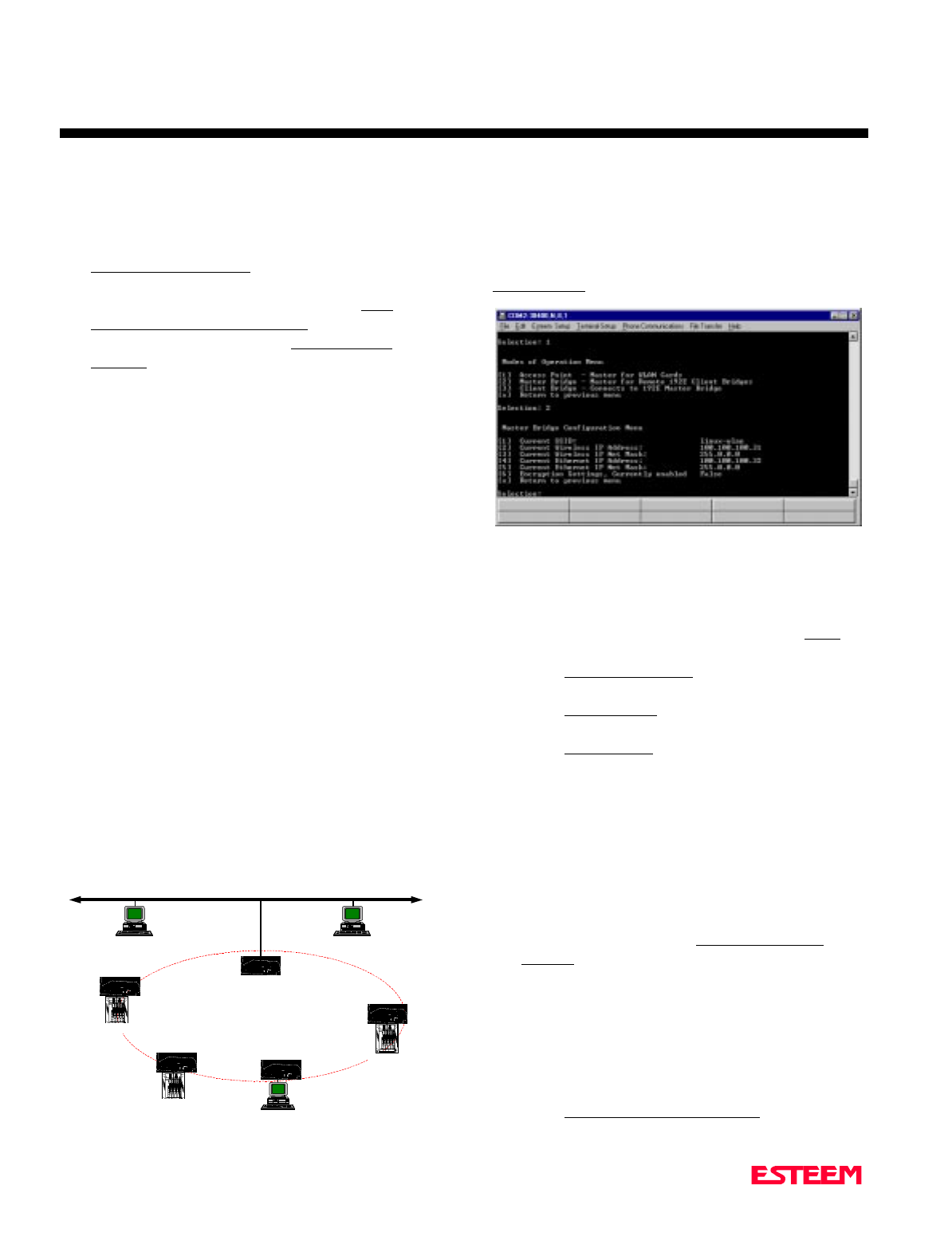
Access Point Configuration
In this network one of the ESTeem Model 192E modems
is configured as the “Access Point”. This Access Point is
then used to bridge wireless network to the cabled LAN
network or act as the center point on a stand alone
wireless network. When configured in this type of
Figure 2: Radio Configuration Menu
CHAPTER 2
APPLICATION PROGRAMMING
Revised: 2 Oct 01 2-4
network, all wireless cards (ESTeem Model WLANC11)
communicate only with the Access Point that serves the
Wireless Local Area Network (WLAN) as a HUB.
Multiple Access Points can be configured in the network
to extend the coverage area of the wireless cards. The
wireless cards will automatically change between Access
Points (Roam) as long as they are all configured with the
same SSID and Wired Equivalent Privacy (WEP)
information. This type of network can extend the range
of the wireless cards greater than they can directly
communication with each other.
The Access Point is responsible for maintaining a logical
link between the clients and providing the wireless
clients with access to information on the wired LAN
network. Figure 3 shows an example of the Model 192E
in an Access Point Configuration.
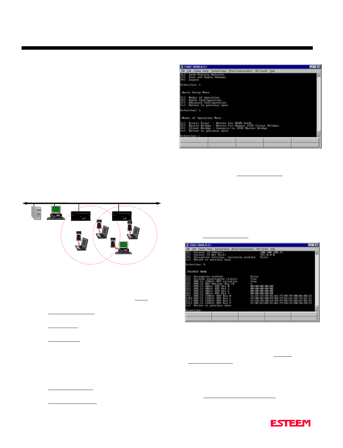
To configure the ESTeem Model 192E as an Access
Point, please use the following:
1. From the Configuration Main Menu, select Setup
(1<Enter>).
2. Select Modes of Operation (1<Enter) to enter the
system configuration menu (Figure 4).
3. Select Access Point (1<Enter>) to open the Access
Point configuration screen.
4. Select Current SSID (1<Enter>) and type in the
SSID information for your WLAN.
Note: The SSID is the unique identification for your
wireless network. All 802.11b devices that share a
wireless network MUST have the same SSID code. This
identification code is case sensitive and must NOT
contain spaces.
5. Select Current IP Address (2<Enter>) to assign the
ESTeem an IP address.
6. Select Current IP Net Mask (3<Enter>) to change
the ESTeem Net Mask.
7. If the wireless network is going to be using WEP
security codes, press Encryption Settings (4<Enter>)
to enter the Privacy Menu (Figure 5) otherwise leave
the setting at “False” and skip to Step 12.
Note: Setting the WEP security codes are highly
recommended for network privacy. They do require
extensive network administration, but if used correctly
they can provide the same level of security as a wired
network.
8. If WEP security is going to be used in the WLAN,
select Encryption Enabled (1<Enter>) and value will
change to “True”.
9. If you wish to keep clients without the correct WEP
code from entering your WLAN, set Exclude
unencrypted clients (2<Enter>) to “True” otherwise
set to “False”. If this value is set to “False”, the
Access Point will allow clients without the correct
WEP code and those with the correct WEP code to
join the network as long as all SSID codes match.
10. Select 802.11 128bit WEP encryption (3<Enter>)
and set to “True” if the wireless cards will be using
Ethernet Wired LAN
Mobile Wireless Network With
Overlap Coverage
192E
Model WLANC11 Wireless
LAN Card
192E
10BASE-T 10BASE-T
Figure 3: Access Point Diagram
Figure 4: Access Point Configuration Menu
Figure 5: Privacy Menu
CHAPTER 2
APPLICATION PROGRAMMING
Revised: 2 Oct 01 2-5
128bit WEP encryption. If using 40bit WEP
encryption, leave at “False”.
11. Load the WEP Key values in sections 4-12. Review
all your changes on the screen are correct and select
Return to previous menu (X<Enter>) to return to the
Access Point Configuration Menu.
12. If all configurations appear correct, press Load
Values and Return to Main Menu (M<Enter>).
13. Once at the Main Menu, press Save and Apply
Changes (7<Enter>) and Yes (Y<Enter>) to reboot
the ESTeeem.
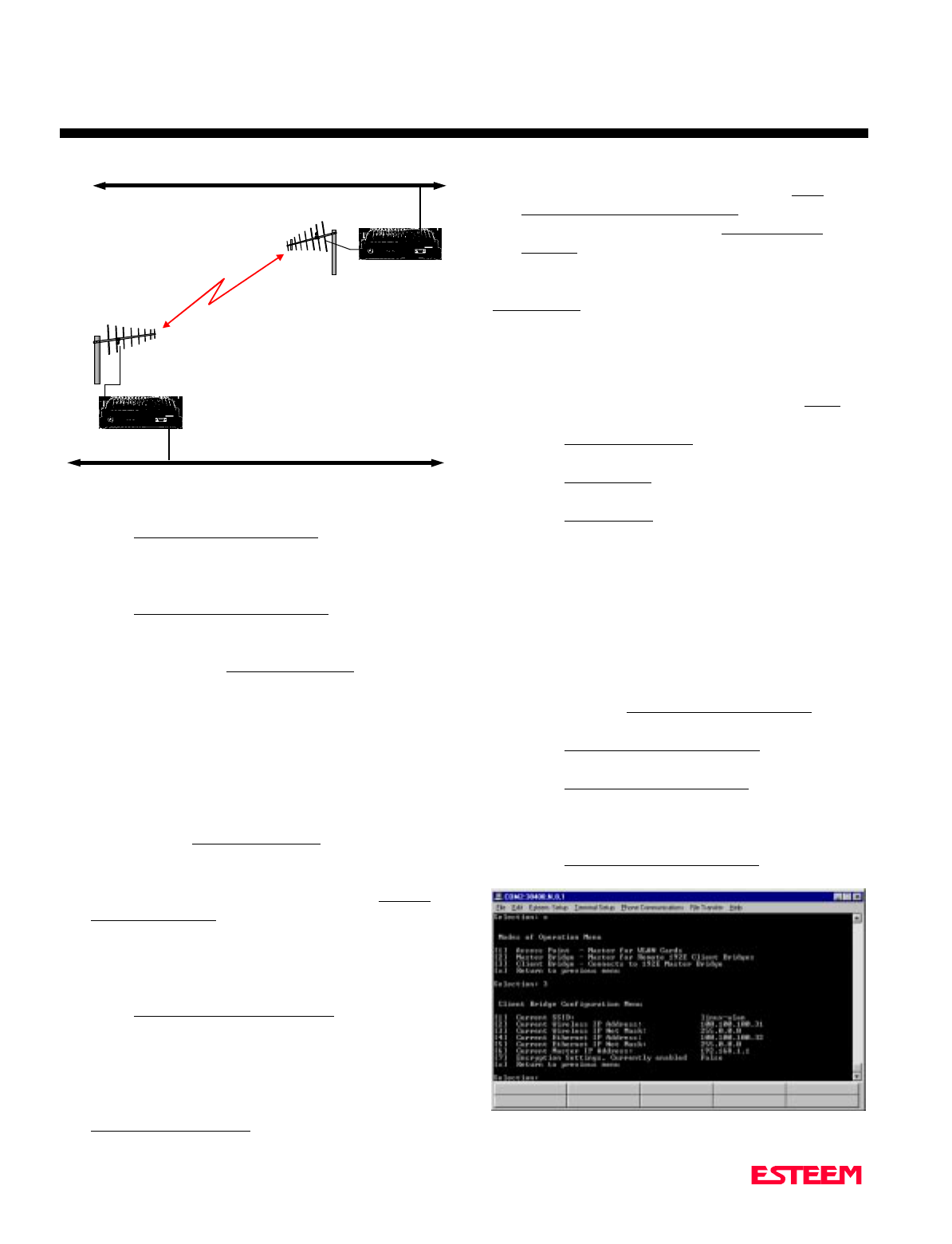
Ethernet Bridging Configuration
The Ethernet Bridging network allows the Model 192E
modems to provide links between two or more Ethernet
segments on a network. Ethernet segments can be either
single network clients such as computers or PLCs or ties
into building LAN networks such as HUBs or switches.
This type of network can provide tremendous flexibility
in your wireless network configurations and also provide
a much greater range than available through the wireless
card network as described in the Access Point section.
Figure 6 shows an example of an Ethernet Bridging
network.
The Bridging Mode has two possible configurations,
Master Bridge and Client Bridge (Figure 6). A bridging
networks can only have one ESTeem Model 192E
configured as a Master Bridge. A 192E configured as a
Client Bridge can communicate with another 192E
configured as a Client Bridge, but the Ethernet data
MUST be routed through a Master Bridge first. The two
Client Bridge modems do not communicate directly,
therefore all bridge networks must have at least one 192E
configured as the Master Bridge. For example, in a
simple point to point wireless Ethernet network, one
Model 192E will be configured as a Master Bridge and
one will be configured as a Client Bridge.
Master Bridge
To configure the ESTeem Model 192E as a Master
Bridge, please use the following:
1. From the Configuration Main Menu, select Setup
(1<Enter>).
2. Select Modes of Operation (1<Enter) to enter the
system configuration menu (Figure 4).
3. Select Master Bridge (2<Enter>) to open the Master
Bridge configuration menu (Figure 7).
4. Select Current SSID (1<Enter>) and type in the
SSID information for your bridge network.
Note: The SSID is the unique identification for your
wireless network. All ESTeem Model 192Es in the
bridge network MUST have the same SSID code. This
identification code is case sensitive and must NOT
contain spaces.
5. Two unique IP addresses are required for the
ESTeem Model 192E in bridging mode. Both the
WLAN port and the 10BaseT port need a unique IP
number (Figure 8). Select Current Wireless IP
Address (2<Enter>) to assign the ESTeem an IP
address.
Note: To gain access to the Model 192E through Telnet
while configured in Bridge Mode, the Wireless IP and
the Ethernet IP address must be on unique Subnets.
Contact your system network administrator for further
information on what IP address should be used in the
subnet.
6. Select Current Wireless IP Net Mask (3<Enter>) to
change the ESTeem Net Mask.
Figure 7: Master Bridge Configuration
10BASE-T
192E - Master
Bridge
Ethernet Wired LAN
Master Bridge
Programming
Terminal
HMI Terminal
Remote PLC
Remote PLC
Remote PLC
192E- Client
Bridge
192E- Client
Bridge
192E- Client
Bridge
192E- Client
Bridge
Figure 6: Bridging Mode Diagram
CHAPTER 2
APPLICATION PROGRAMMING
Revised: 2 Oct 01 2-6
7. Select Current Ethernet IP Address (4<Enter>) to
assign the ESTeem an IP address.
Note: The Ethernet IP and the Wireless IP addresses
must NOT be the same.
8. Select Current Ethernet IP Net Mask (5<Enter>) to
change the ESTeem Net Mask.
9. If the bridge network is going to be using WEP
security codes, press Encryption Settings (6<Enter>)
to enter the Privacy Menu (Figure 5) otherwise leave
the setting at “False” and skip to Step 14.
Note: Setting the WEP security codes are highly
recommended for network privacy. They do require
extensive network administration, but if used correctly
they can provide the same level of security as a wired
network.
10. If WEP security is going to be used in the bridge
network, select Encryption Enabled (1<Enter>) and
value will change to “True”.
11. If you wish to keep clients without the correct WEP
code from entering your bridge network, set Exclude
unencrypted clients (2<Enter>) to “True” otherwise
set to “False”. If this value is set to “False”, the
Access Point will allow clients without the correct
WEP code and those with the correct WEP code to
join the network as long as all SSID codes match.
12. Select 802.11 128bit WEP encryption (3<Enter>)
and set to “True” if the wireless cards will be using
128bit WEP encryption. If using 40bit WEP
encryption, leave at “False”.
13. Load the WEP Key values in sections 4-12. Review
all your changes on the screen are correct and select
Return to previous menu (X<Enter>) to return to the
Access Point Configuration Menu.
14. If all configurations appear correct, press Load
Values and Return to Main Menu (M<Enter>).
15. Once at the Main Menu, press Save and Apply
Changes (7<Enter>) and Yes to reboot the
ESTeeem.
Client Bridge
To configure the ESTeem Model 192E as a Client
Bridge, please use the following:
1. From the Configuration Main Menu, select Setup
(1<Enter>).
2. Select Modes of Operation (1<Enter) to enter the
system configuration menu (Figure 4).
3. Select Client Bridge (3<Enter>) to open the Client
Bridge configuration menu (Figure 9).
4. Select Current SSID (1<Enter>) and type in the
SSID information that matches the Master Bridge.
Note: The SSID is the unique identification for your
wireless network. All ESTeem Model 192Es in the
bridge network MUST have the same SSID code. This
identification code is case sensitive and must NOT
contain spaces.
5. Two unique IP addresses are required for the
ESTeem Model 192E in bridging mode. Both the
WLAN port and the 10BaseT port need a unique IP
number. Select Current Wireless IP Address
(2<Enter>) to assign the ESTeem an IP address.
6. Select Current Wireless IP Net Mask (3<Enter>) to
change the ESTeem Net Mask.
7. Select Current Ethernet IP Address (4<Enter>) to
assign the ESTeem an IP address.
Note: The Ethernet IP and the Wireless IP addresses
must NOT be the same.
8. Select Current Ethernet IP Net Mask (5<Enter>) to
change the ESTeem Net Mask.
Ethernet Wired LAN
Ethernet Wired LAN
192E - Client
Brid
g
e
192E - Master
Brid
g
e
Ethernet IP Address (Example)
192.168.1.0
Ethernet IP Address (Example)
192.168.1.1
Wireless IP Address (Example)
192.168.2.1
Wireless IP Address (Example)
192.168.2.0
Figure 8: IP Addressing Diagram
Figure 9: Client Bridge Configuration
CHAPTER 2
APPLICATION PROGRAMMING
Revised: 2 Oct 01 2-7
9. Select Current Master IP Address (6<Enter>) to
input the Wireless IP address of the Master Bridge.
Note: The Master IP address must match the Wireless IP
address of the Master Bridge for the bridging mode to
function correctly.
10. If the bridge network is going to be using WEP
security codes, press Encryption Settings (7<Enter>)
to enter the Privacy Menu (Figure 5) otherwise leave
the setting at “False” and skip to Step 15.
Note: Setting the WEP security codes are highly
recommended for network privacy. They do require
extensive network administration, but if used correctly
they can provide the same level of security as a wired
network.
11. If WEP security is going to be used in the bridge
network, select Encryption Enabled (1<Enter>) and
value will change to “True”.
12. If you wish to keep clients without the correct WEP
code from entering your bridge network, set Exclude
unencrypted clients (2<Enter>) to “True” otherwise
set to “False”. If this value is set to “False”, the
Access Point will allow clients without the correct
WEP code and those with the correct WEP code to
join the network as long as all SSID codes match.
13. Select 802.11 128bit WEP encryption (3<Enter>)
and set to “True” if the wireless cards will be using
128bit WEP encryption. If using 40bit WEP
encryption, leave at “False”.
14. Load the WEP Key values in sections 4-12. Review
all your changes on the screen are correct and select
Return to previous menu (X<Enter>) to return to the
Access Point Configuration Menu.
15. If all configurations appear correct, press Load
Values and Return to Main Menu (M<Enter>).
16. Once at the Main Menu, press Save and Apply
Changes (7<Enter>) and Yes to reboot the
ESTeeem.
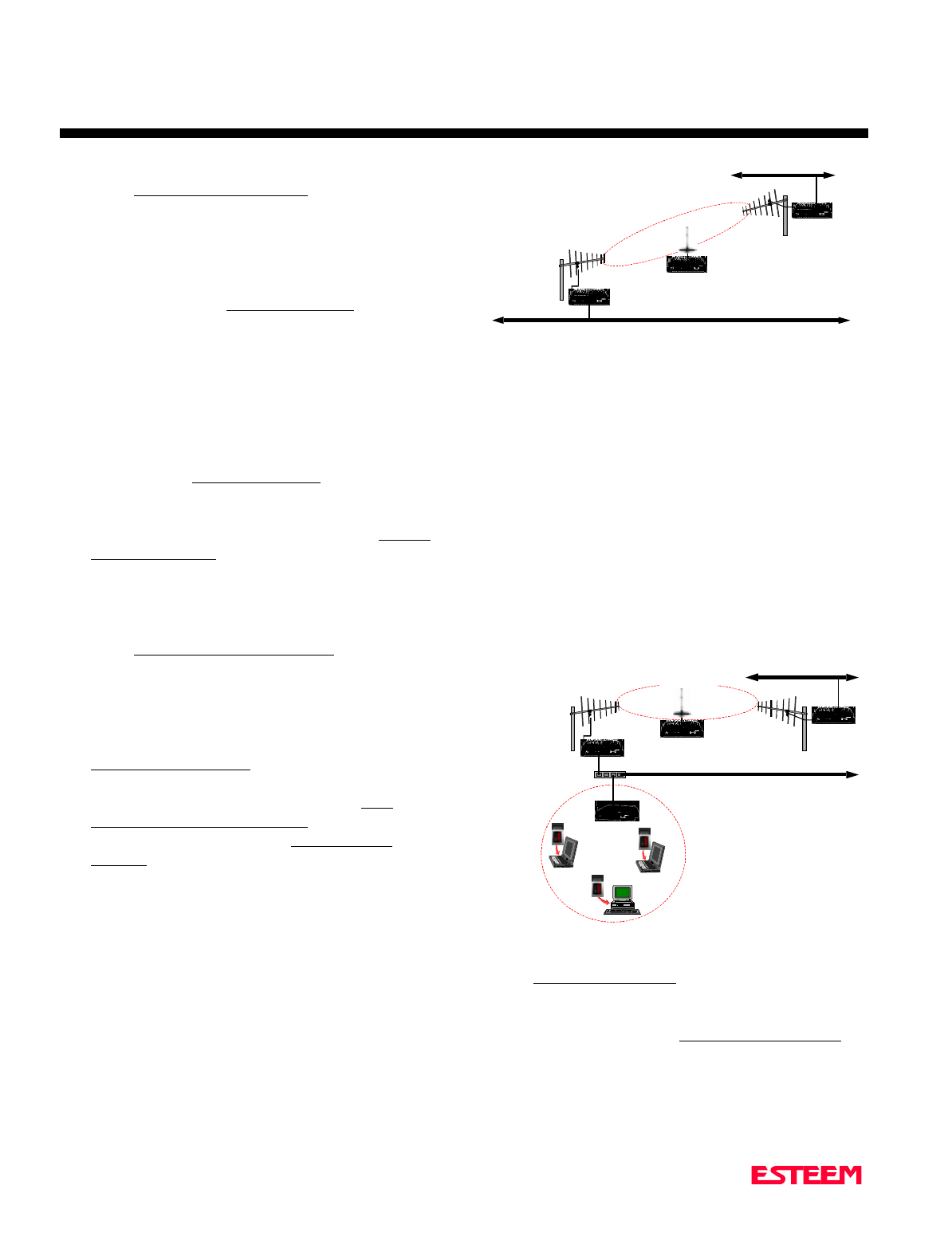
Repeater Configuration in Bridging Mode
To add a repeater site to a bridging mode system can be
accomplished simply configuring the repeater location as
a Master Bridge and all other locations as Client Bridges
(Figure 10). Follow the steps for configuring the Master
and Client Bridges above to complete the ESTeem Model
192E programming.
Combined Access Point and Ethernet Bridging
Configuration
As the name would imply, this type of network is a
combination of an Access Point network and an Ethernet
Bridging network. This type of network would provide
both communication to a Building LAN network from a
remote Model 192E and also provide wireless access to
the network for the wireless cards. This type of network
requires two ESTeem Model 192E modems and at least a
three port Ethernet HUB. Figure 11 shows a combined
network. Follow the steps for configuring the Access
Point, Master and Client Bridges in this chapter to
complete the ESTeem Model 192E programming.
LOADING FACTORY DEFAULT VALUES
To return the ESTeem Model 192E to the factory default
values, login to the Configuration Menu (Figure 1) and
select Load Factory Defaults (6<Enter>). A message that
the factory default settings were restored will appear and
the Configuration Menu will reload. To keep these
factory default values, select Save and Apply Changes
(7<Enter>) and then Yes to reboot the ESTeem.
Ethernet Wired LAN
Digi-Repeating
Ethernet Wired LAN
192E - Master
Bridge
192E- Client
Bridge
192E- Client
Bridge
Figure 10: Repeater Configuration
Ethernet Wired LAN
Mobile Wireless Network
Model WLANC11
Wireless LAN Card
192E
10BASE-T
192E
192E
Ethernet Wired LAN
LAN Bridging
Digi-Repeating
192E
Ethernet Hub
Figure 11: Combined System Diagram

CHAPTER 3
INTERFACING
SERIAL INTERFACE CONFIGURATION
RS-232 PORT PINOUT TABLE
ETHERNET INTERFACE

CHAPTER 3
INTERFACING
Revised: 15 Oct 01 3-2
SERIAL INTERFACE CONFIGURATION
The ESTeem Model 192E has a standard RS-232C, 9-pin
Female connector for interfacing directly with the serial
port on the computer. Use ESTeem part number AA062
to interface the Model 192E with a 9-pin serial port on a
computer.
The serial port on the ESTeem Model 192E can be used
to access the configuration menu in the ESTeem for
system and network configuration. The ESTeem
communications port operates at 19,200 bps, No Parity, 8
Data Bits and 1 Stop Bit (19,200,N,8,1). Configure your
terminal program to match these settings.
RS-232 PORT PIN-OUT TABLE
ESTeem Model 192E
RS-232C Port Pin-Out Table
Pin No. Function
1Data Carrier Detect (DCD)
2Receive Data (RxD)
3Transmit Data (TxD)
4Data Terminal Ready (DTR)
5Signal Ground
6Data Set Ready (DSR)
7Request To Send (RTS Input)
8Clear To Send (CTS)
9Ring Line (RI)
ETHERNET INTERFACE
The ESTeem Model 192E’s Ethernet Port is configured
to directly interface with an Ethernet HUB using a
straight through 10BaseT cable. If the ESTeem is
connected to a network interface card (NIC), you will
need to use 10BaseT reversing cable.

CHAPTER 4
ANTENNAS
ANTENNA AND CABLE CONFIGURATIONS
WEATHER PROOFING COAXIAL CONNECTORS
GROUNDING
LIGHTINING ARRESTORS
MODEL 192E TYPICAL OUTDOOR ANTENNA
INSTALLATION DIAGRAM
MODEL 192E TYPICAL INDOOR ANTENNA INSTALLATION
DIAGRAMS
ESTEEM SWR MEASUREMENT BLOCK DIAGRAM
CHAPTER 4
ANTENNAS
Revised: 15 Oct 01 4-2
ANTENNA AND CABLE
CONFIGURATIONS
Warning: Only the tested cable lengths and antennas
provided by EST meet the FCC maximum peak output
power requirements. Any other combination of
antennas or coax cables is not authorized.
EST offers three (3) different types of antennas for both
indoor and outdoor configurations.
Part Number: AA01S
Omni Directional Rubber Duck Antenna.
Unity Gain
Directly mounts to antenna port
Part Number: AA20S
Omni Directional Building Mount Antenna
5 dBd gain
Uses either 25’ RG-8 Cable (Indoor) or
50’ Heliax Cable (Outdoor)
Part Number: AA202S* (Point-to-point ONLY)
Directional Building Mount Antenna
13.9 dBd gain
50’ Heliax Cable (Outdoor) with Lightning Arrestor
(EST P/N: AA164) and RG-8 Patch Cable
Outdoor Fixed Base Configuration
AA20S or AA202S Antenna
Lightning Protection
50’ Heliax Cable
Indoor Configuration
AA20S or AA202S Antenna
25’ RG-8 Cable
Warning: Only pre-made coax cables from the factory
used in conjunction with either the AA20S
omni-directional or AA202S directional
antenna meet all FCC Section 15.247(b)
EIRP maximum power requirements.
*Use of the AA202S, directional antenna
is limited to fixed point to point
applications only. In accordance FCC
Section 15.247(b)iii, the operator or
installer is responsible for ensuring the
systems is used exclusively for fixed, point-
to-point applications.
COAXIAL CABLES
The 25’ length of RG-8 coax cable and the 50’ length of
Heliax cable are the minimum cable lengths allowed for
use the above antennas. Listed below are representative
cable losses in db/100 ft at the 2.4 GHz frequency range:
Frequency (MHz) RG-8 ½” Heliax
---------------------------------------------------------------------
2400-2462 - 10.0 - 3.74
In a severe noise environment it may be necessary to use
a double shield type of coax cable such as RG-214/U in
place of the RG-8. This cable must be purchased from
the factory to meet FCC requirements.
Note: A -3 dB loss means you have lost 1/2 of your
signal. A +3 dB gain means you have doubled
(x2) your signal.
WEATHER PROOFING COAX
CONNECTIONS
1. Coat the threads of the connectors with silicone
lubricant prior to assembly (See Note 1) and hand
tighten. Care should be taken not to get any
lubricant on the center conductor.
2. Wrap the connector assembly with a vapor barrier
patch for weather proofing (See Note 2), ensuring to
overlap onto the coax cable approximately 1 1/2
inches.
3. Apply an electrical coating (sealing agent) over the
vapor barrier patch for added protection (See Note
3).
Notes:
1. Dow Corning RTV-3140 or equivalent.
2. Suggested vendors:
VAPOR-WRAP
Decibel Products
3184 Quebec St.
Dallas, TX 75356
214-631-0310
VYNIL-MASTIC, P/N 2200
3-M Company
Customer Service
512-984-1800
3. SCOTCHKOTE, 3-M Company, or equivalent.

CHAPTER 4
ANTENNAS
Revised: 15 Oct 01 4-3
GROUNDING
All building mount antennas require attachment to a
good earth ground for optimum efficiency. Contact a
reputable local communications shop for procedures for
your area.
LIGHTNING ARRESTORS
Lightning arrestors should be used on all external
building mount antennas for personal protection and to
minimize damage to the transceiver during lightning
storms. The units should be installed as per
manufacturers instructions provided with the device.
CHAPTER 4
ANTENNAS
Revised: 15 Oct 01 4-4
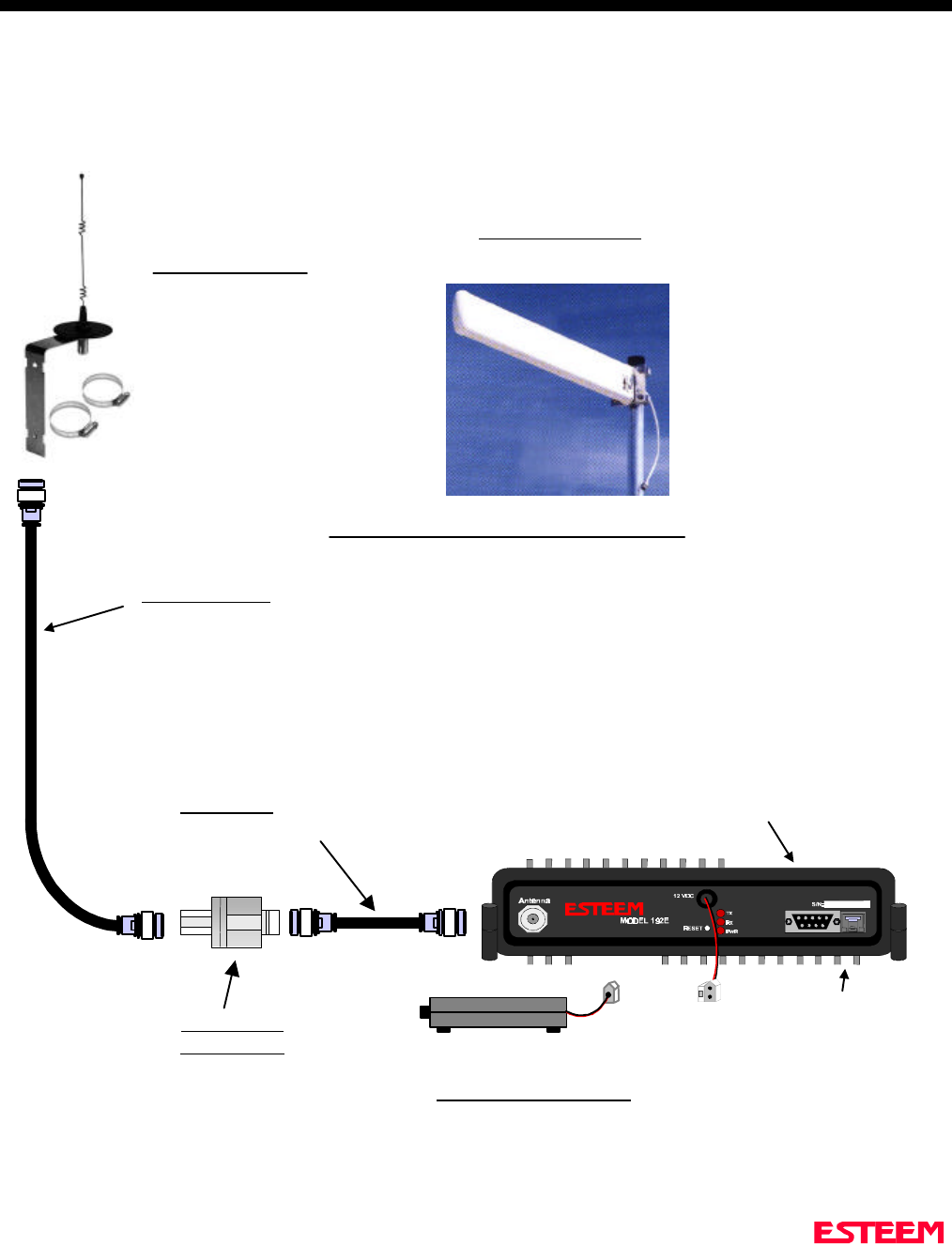
Model 192E
Outdoor Fixed Base Site Diagram
ANTENNA
CONFIGURATIONS
Heliax Feedline
50 ft.
TNC-R
Male Connector
LIGHTNING
ARRESTOR
12 VDC POWER SUPPLY
RECOMMENDATIONS
EST P/N AA174
Battery Packs
Solar Power
2 Pin Molex
Connector
RG-8 Coax
2 ft.
RS-232 Interface
Connector
Directional Antenna
EST P/N AA202S.
Omni-Directional
Antenna
EST P/N AA20S.
Caution
To comply with the FCC
exposure compliance
requirements, a separation
distance of at least 7 cm must
be maintained between the
antenna and all persons.
Caution
To comply with the FCC
exposure compliance
requirements, a separation
distance of at least 19 cm
must be maintained between
the antenna and all persons..
RJ-45 Ethernet
Connector
NOTES
1. Vapor wrap all external antenna coax
connections with vinyl wrap (EST Part No. AA241)
and apply Scotchkote Electrical Coating (EST Part
No. AA242).
2. Contact EST for recommendations regarding
antenna mounting hardware and installation tips.
3. Ground antenna structure, base and lightning
arrestor.
TNC-R
Male Connector
TNC-R
Male
Connector
TNC-R
Male
Connector
CHAPTER 4
ANTENNAS
Revised: 15 Oct 01 4-5
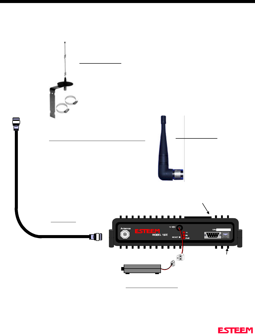
Model 192E Indoor Equipment Diagram
Omni-Directional
Antenna
EST P/N AA20S.
Caution
To comply with the FCC
exposure compliance
requirements, a separation
distance of at least 7 cm
must be maintained
between the antenna and
all persons.
RE
SET
TNC-R
Male Connector
12 VDC POWER SUPPLY
RECOMMENDATIONS
EST P/N AA174
Battery Packs
Solar Power
2 Pin Molex
Connector
RG-8 Coax
25 ft.
RE
SET
Omni-Directional
Antenna
EST P/N AA01S.
Rubber duck, back
of set mount
RJ-45 Ethernet
Connector
RS-232 Interface
Connector
NOTES
1. Vapor wrap all external antenna coax
connections with vinyl wrap (EST Part No. AA241)
and apply Scotchkote Electrical Coating (EST Part
No. AA242).
2. Contact EST for recommendations regarding
antenna mounting hardware and installation tips.
3. Ground antenna structure, base and lightning
arrestor.
TNC-R
Male Connector
CHAPTER 4
ANTENNAS
Revised: 15 Oct 01 4-6
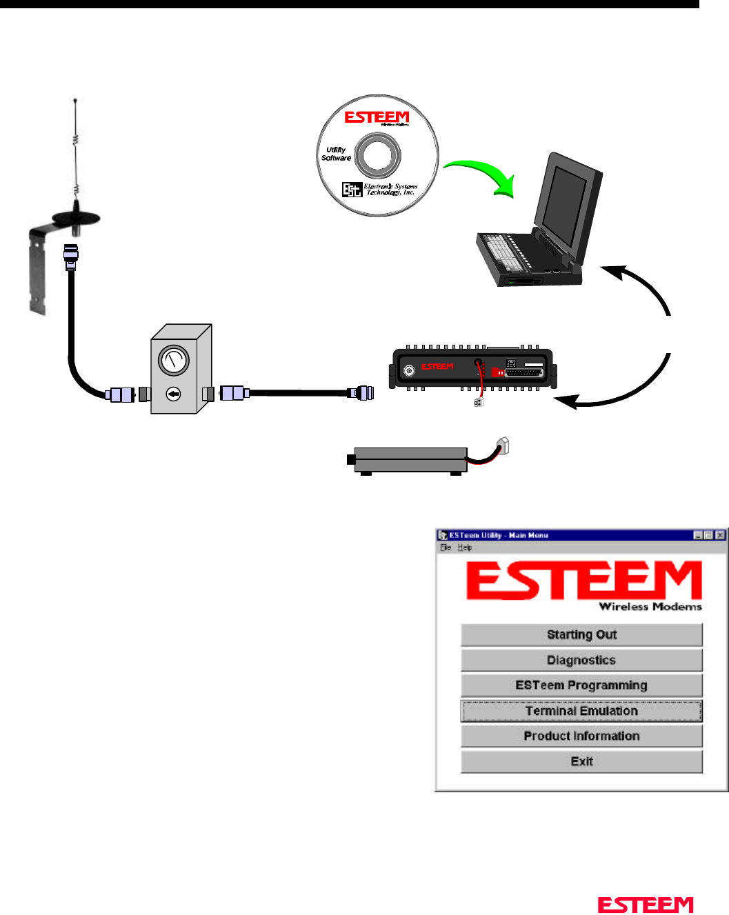
ESTeem SWR Measurement Block Diagram
N Male
Connector N Male
Connector
Antenna
2 Pin Molex
Connector
RS-232C Interface Cable
(EST P/N AA062)
SWR Meter
RG-8 Cable
(EST P/N AA230)
12 VDC Power Supply
(EST P/N AA174)
S/N:T/E
TX
RX
PWR
IR
Port
Phone
Model 192S
Antenna 12 VDC
RESET
ESTeem Model 192 Utility
Software Windows Version
TNC-R Male
Connector
TNC-R Male
Connector
Caution
To comply with the FCC exposure
compliance requirements, a
separation distance of at least 7 cm
for an omni-directional and 19 cm for
a directional antenna must be
maintained between the antenna and
all persons.
Note
The cables listed above are only
available with the purchase of an
SWR Meter.
Programming the ESTeem Model 192E For SWR Measurements
1. Configure the hardware as per the above diagram.
2. Install the ESTeem Utility on the PC hard drive as per instructions
with the software.
3. From Utility Main Menu (Figure 1) select the Terminal Emulation
Mode.
4. In the Terminal Emulation Mode press the Enter key to display the
Model 192E configuration menu.
5. Select the Turn Transmitter ON option.
6. When the testing is completed, select Turn Transmitter OFF option on
the configuration menu.
Figure 1: ESTeem Utility Main Menu

APPENDICES
APPENDIX “A” FCC INFORMATION (USA Only)
APPENDIX “B” SPECIFICATIONS
ESTeem Specifications
Antenna Specifications

APPENDIX A
FCC LICENSING
Revised: 15 Oct 01 APX A-2
INFORMATION TO USERS
The ESTeem Model 192E complies with Part 15 of the
FCC Rules. Operation is subject to the following two
conditions: (1) This device may not cause harmful
interference, and (2) this device must accept any
interference received, including interference that may
cause undesired operation.
Note to User:
Changes or modifications to this equipment not expressly
approved by Electronic Systems Technology for
compliance could void the user's authority to operate the
equipment.
Other Information
Model 192E
Direct Sequence
FCC Type Acceptance No: ENPESTEEM192E

APPENDIX A
FCC LICENSING
Revised: 15 Oct 01 APX A-3
FEDERAL COMMUNICATIONS COMMISSION FIELD OFFICES
ALASKA
1011 E. Tudor Rd.
Rm 240 Box 2955
Anchorage, AK 99510
CALIFORNIA
7840 El Cajon Blvd
Suite 405
La Mesa, CA 92041
3711 Long Beach Blvd
Suite 501
Long Beach, CA 90807
323A Battery St
San Francisco, CA 94111
COLORADO
Executive Tower
1405 Curtis St
Suite 2925
Denver, CO 80202
FLORIDA
919 Federal Bldg
51 SE First Ave.
Miami, FL 33130
1211 N. Westshore
Suite 601
A.D. P. Building
Tampa, FL 33607
GEORGIA
Massell Bldg. 440
1365 Peachtree NE
Atlanta, GA 30309
HAWAII
7304 Prince Kuhi
Federal Building
Honolulu, HI
HAWAII
300 Almoana Blvd.
P.O. Box 50023
Honolulu, HI
ILLINOIS
3935 Federal Bldg
230 S. Dearborn
Chicago, IL 60604
LOUISIANA
1009 Edw Hebert Bldg.
600 South Street
New Orleans, LA 70130
MARYLAND
1017 Geo. Fallon
Building 31
Hopkins Plaza
Baltimore, MD
MASSACHUSETTS
1600 Customhouse
165 State Street
Boston, MA 02109
MICHIGAN
1054 Federal Building
231 W LaFayette
Detroit, MI 48225
MINNESOTA
691 Federal Building
316 N Robert St.
St. Paul, MN
MISSOURI
Brywood Office Tower
6800 E. 63rd Street
Kansas City, MO
NEW YORK
1307 Federal Building
111 W. Huron
Buffalo, NY 14202
201 Varick Street
New York, NY 10014
OREGON
1782 Federal Building
1220 SW 3rd Avenue
Portland, OR 97204
PENNSYLVANIA
Room 404
2300 E. Lincoln H
Langhorne, PA
PUERTO RICO
747 Federal Building
Carlo Chardon Ave.
Hato Rey, PR 00918
TEXAS
Cabeli Building
1100 Commerce
Dallas, TX 75242
5636 Federal Building
515 Rusk Avenue
Houston, TX 77002
VIRGINIA
Military Circle
870 N. Military Hwy.
Norfolk, VA 23502
WASHINGTON
3256 Federal Building
915 Second Avenue
Seattle, WA 98174

APPENDIX B
SPECIFICATIONS
Model 192E Specifications
Revised: 15 Oct 01 APX B-1
LED INDICATORS
• Power On
• Receiver Carrier Detect
• Transmitter Enable
I/O – CONNECTORS
• RS-232C - 9 Pin Sub D Female
• RJ-45 10BaseT Connection
• Antenna Output – TNC-R
• Input Power - 2 Pin Molex
Female
DATA INPUT
• RS-232 Asynchronous
• 38,400 bps Fixed Data Rate
• 8 data bits
• No parity
• One Stop Bit
FREQUENCY OF
OPERATION
• 2412 to 2462 MHz.
• Frequency selectable in 11
frequency zones
RF DATA RATE
• 1-11 Mbps RF data rate
TRANSMITTER
• 1 Watt RF output
• 100% duty cycle
• 50 ohms output impedance
• Protocol activated keying
• 10 µsec typical latency
• Direct sequence spread spectrum
RECEIVER
• Double conversion
superheterodyne
• -93 dBm 8E-2 Frame Error Rate
• 80 dB Image Rejection
• > 35 dBm Adjacent Channel
Rejection
POWER REQUIREMENTS
• 11-16 VDC @ 700 ma Transmit
300 ma Receive
SIZE
• 2.45 in. Height
8.16 in. Width
9.37 in. Length
WEIGHT:
• 4.6 lbs.
• Rugged die cast aluminum case
ENVIRONMENT
• -30° to 50° C
• 95% Non-condensing
WARRANTY
• 1 Year
APPENDIX B
SPECIFICATIONS
Model 192E Antennas
Revised: 15 Oct 01 APX B-2
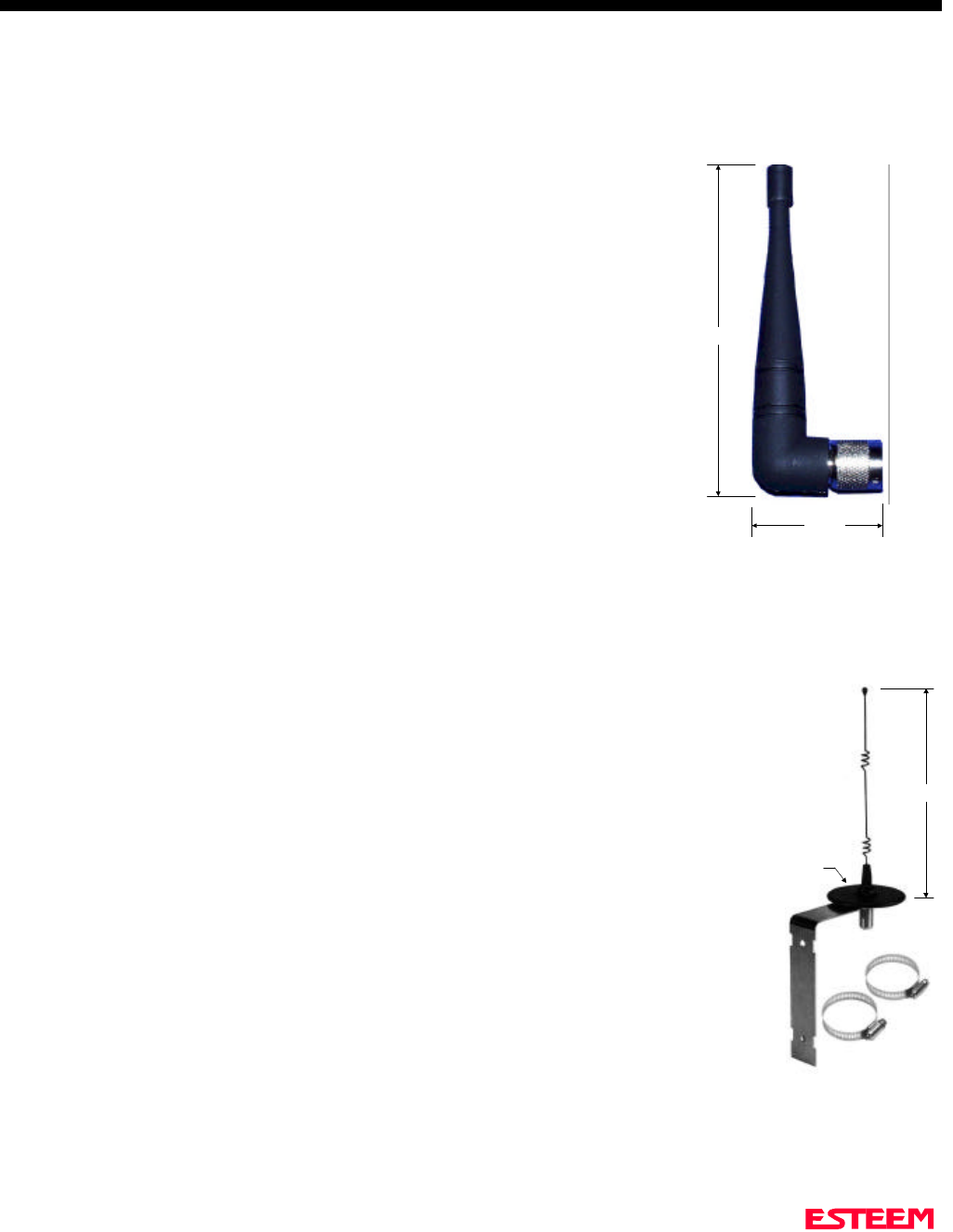
Model No: AA01S
Antenna Type: Omni-Directional, right angle rubber duck, ½ wave
Applications:Back of ESTeem Model 192S mount.
Frequency: 2400 to 2485 MHz
Polarization: Vertical
Impedance: 50 ohms
Gain: 2 dBd
VSWR: < 1.5
Front To Back Ratio: n/a
Horizontal Beamwidth: n/a
Vertical Beamwidth: n/a
Antenna Material: Rubber duct whip.
Mounting Hardware: n/a
Antenna Connector:TNC-R Male
Antenna Envelope: 4 in. length by 1.5 in width
Weight: .08 lbs.
Model No: AA20S
Antenna Type: Omni Directional, 5/8 Wave over 5/8 Wave over ¼ Wave.
Applications:Fixed base or mobile mount.
Frequency: 2400 to 2485 MHz
Polarization: Vertical
Impedance: 50 ohms
Gain: 5 dBd
VSWR: < 1.5
Front To Back Ratio: n/a
Horizontal Beamwidth: n/a
Vertical Beamwidth: n/a
Antenna Material: Stainless steel whip. All other hardware anodized metal.
Mounting Hardware: Stainless steel clamps for mounting to ¾ in. to 1½ in. pipe
with right angle mount of direct panel mount..
Antenna Connector:TCN-R Female.
Antenna Envelope: 9 in. length by 3.5 in. width
Weight: .4 lbs.
3.5 in. Dia.
Right Angle
Mounting
Bracket
Stanless
Steel
Clamps
9 in.
Model AA20S
4 in.
1.5 in.
Model AA01S
Caution
To comply with the FCC
exposure compliance
requirements, a separation
distance of at least 7 cm must
be maintained between the
antenna and all persons.

APPENDIX B
SPECIFICATIONS
Model 192E Antennas
Revised: 15 Oct 01 APX B-3
Model No: AA202S
Antenna Type: Directional, 15 element yagi in sealed UV
stable radome
Applications:Fixed base.
Frequency: 2400 to 2500 MHz
Polarization: Linear
Impedance: 50 ohms
Gain: 13.9 dBd
VSWR: < 1.5
Front To Back Ratio: 18 dB
Horizontal Beamwidth: 34 degrees
Vertical Beamwidth: 30 degrees
Antenna Material: Stainless hardware with one piece copper
radiating element. Advanced microwave
substrate. All other hardware anodized
metal.
Mounting Hardware: Stainless steel U bolts for mounting to 1.5
in. to 2.2 in. diameter pipe.
Antenna Connector:TNC-R Female on Pigtail
Maximum Power Input: 50 Watts
Antenna Envelope: 26 in. length by 4.0 in. height by 1.5 in. width
Windload (RWV): 125 mph
Wind Load ½ in. Ice: 100 mph
Wind Surface Area: 0.4 ft2
Weight: 1.25 lbs.
Model AA202S
Caution
To comply with the FCC
exposure compliance
requirements, a separation
distance of at least 19 cm
must be maintained between
the antenna and all persons.