Electronic Systems Technology ESTEEM192E User Manual 192E Manual
Electronic Systems Technology 192E Manual
UserManual.wiki
>
Electronic Systems Technology
>
ESTEEM192E User Manual
>
Revised Manual
Contents
1.
User manual
2.
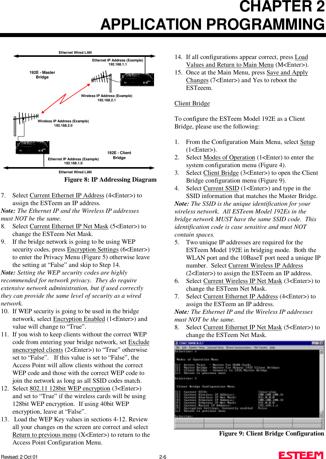
User Manual
3.
Revised Manual
Revised Manual
Navigation menu
Upload a User Manual
Namespaces
Wiki Guide
HTML
PDF
Info
Views
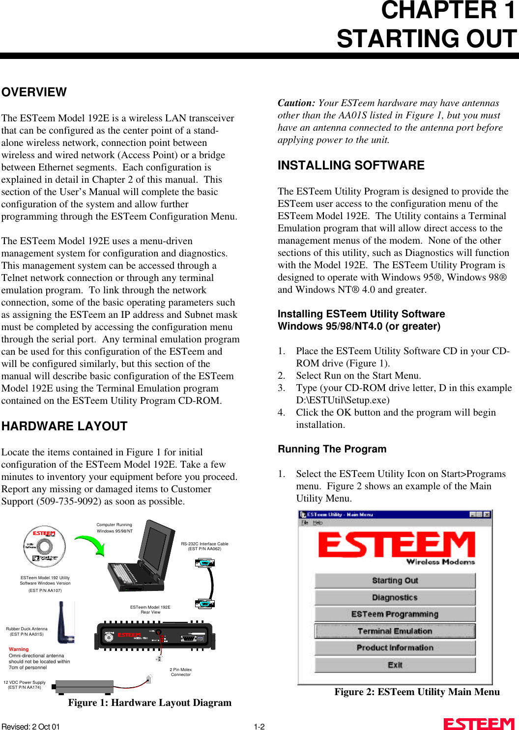
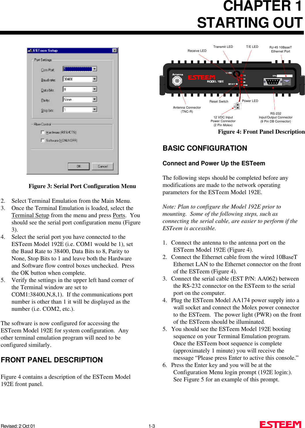
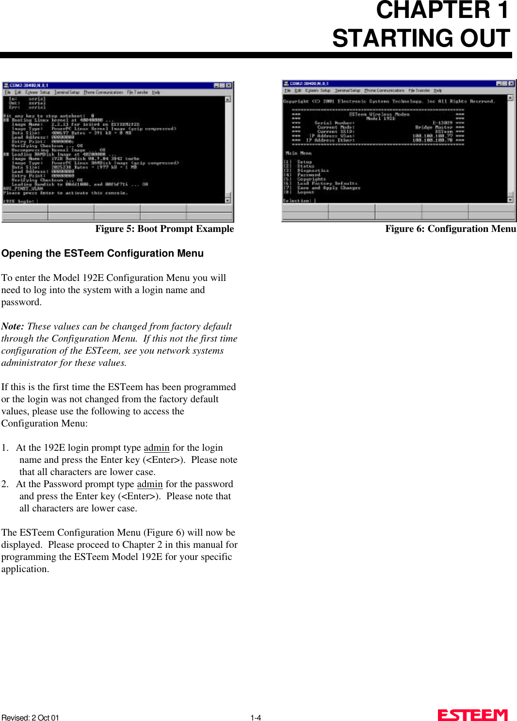
User Manual
Discussion / Help
Navigation