Electronic Systems Technology ESTEEM192MHP Wireless Modem User Manual Chaper 0 Front Cover v3
Electronic Systems Technology Wireless Modem Chaper 0 Front Cover v3
UserManual.wiki
>
Electronic Systems Technology
>
ESTEEM192MHP User Manual
>
Manual Part 1
Contents
1.
Manual Part 1
2.
Manual Part 2
Manual Part 1
Navigation menu
Upload a User Manual
Namespaces
Wiki Guide
HTML
PDF
Info
Views
User Manual
Discussion / Help
Navigation


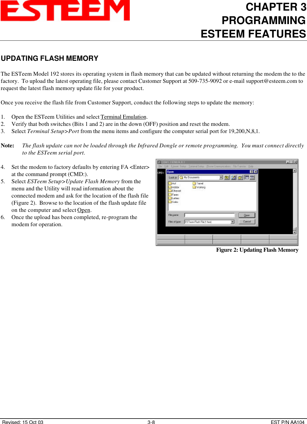
![CHAPTER 3PROGRAMMINGESTEEM FEATURES Revised: 15 Oct 03 3-4 EST P/N AA104MULTI-CONNECTThe actual polling of the ESTeem must originate from the host device connected to the ESTeem using the CONNECT commandto originate the initial connect and the COMMAND character to return from the CONVERSE mode to the COMMAND mode. The first time around the pole a CONNECT data packet (RF transmission) will be initiated. When a link is established, it is heldinternally in the ESTeem connect table. The next time around the pole to the same address, the link status will be checked in theESTeem table. If the address indicates a link has already been established, then only data and its corresponding ACK will betransmitted to that node. This greatly increases polling time by eliminating the usual CONNECT/DISCONNECT sequence eachtime except when communication is first established.The MULTID command allows the user to send data to a specific ESTeem address from the CONVERSE Mode by specifying theESTeem address routing before the data packet. This feature will also display the address of the sending ESTeem on anyreceived data.Example Of Transmitted Data:[001]DATA Routes data to an ESTeem addressed 1.[100,200,250,1]DATA Routes data to an ESTeem addressed 1 via ESTeems addressed 100, 200, and 250.The above example replaces the CONNECT command from the COMMAND Mode. Received data packets will have the address of the ESTeem that sent the data at the beginning of the data packet.Example Of Received Data:[004]RECEIVED DATA Data received from ESTeem addressed 4.[030,100,244,004] Data received from ESTeem addressed 4 via ESTeems addressed 30, 100, and 244.MULTID (on/off) = On Enables this feature. Factory default = OFF.](https://usermanual.wiki/Electronic-Systems-Technology/ESTEEM192MHP.Manual-Part-1/User-Guide-599035-Page-16.png)
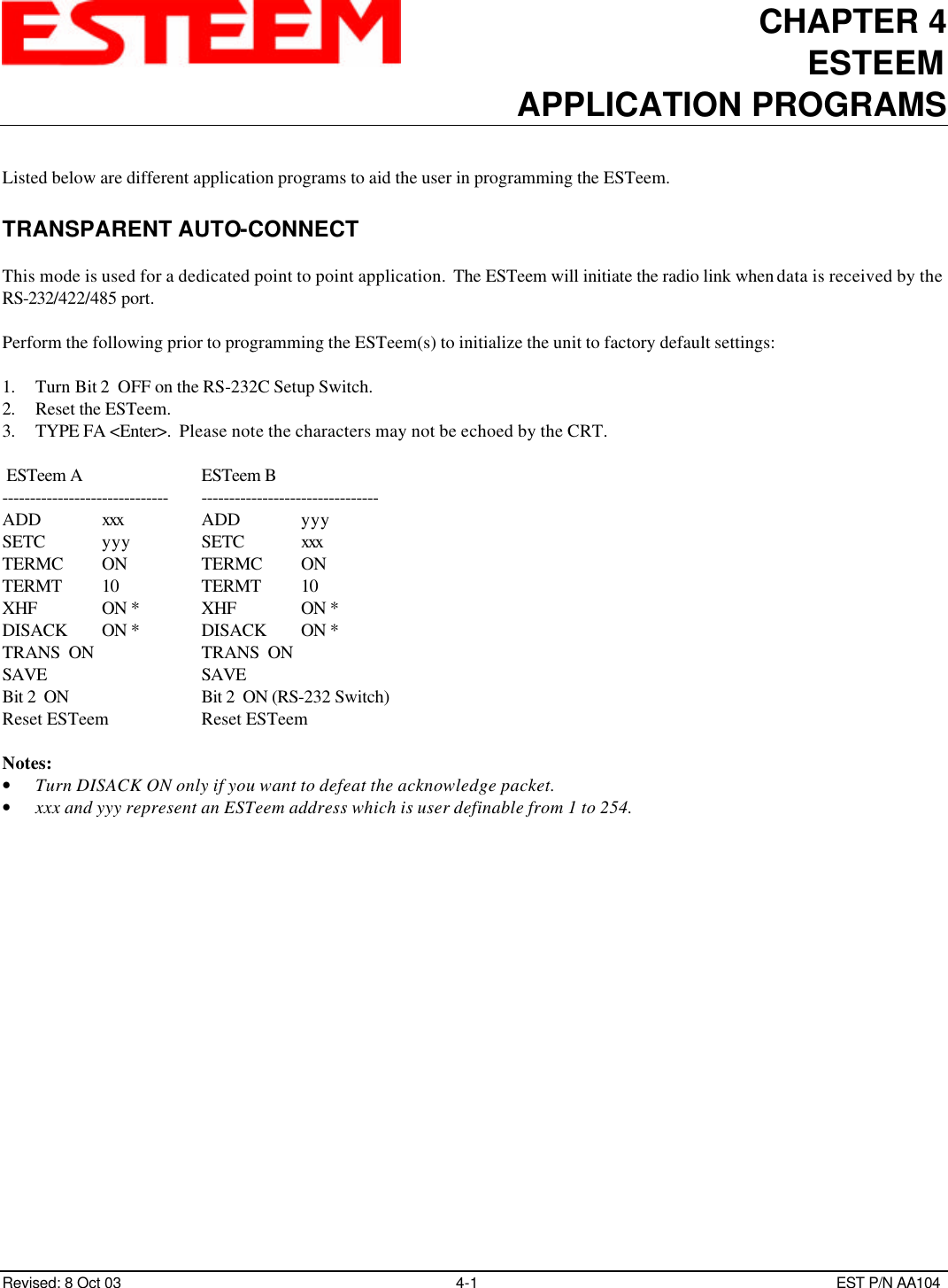
![CHAPTER 3PROGRAMMINGESTEEM FEATURES Revised: 15 Oct 03 3-6 EST P/N AA104HARDWARE RING LINE (Factory Option)When the ESTeem establishes a CONNECT or link with another ESTeem (T/E Light on solid), pin 22 at the ESTeem RS-232C willchange from a -15 vdc voltage state to a +15 vdc voltage state. The RING software command allows the user to change theoutput from a latched state to a pulsed state. To change the state of this line program the following from the COMMANDmode. Factory default = LATCH.RING = Latch. Pin 22 is high when the ESTeem T/E light is on solid.RING = Pulse. Pin 22 is pulsed (positive 250 ms.) when the ESTeem T/E light is on solid.PACKET MONITORThe PACKM [ON/OFF] command places the ESTeem in a special packet monitor mode. When this feature is enabled theESTeem is placed in a receive only mode and will not function as a normal ESTeem. The ESTeem will monitor and report thestatus of all message traffic within the network in the following format, the actual packet message will not be outputted.SA-xxx, DA-xxx, Type Code, R1-Repeater Status, R2-Repeater Status, R3-Repeater Status, Data Bytes Sentxxx =ESTeem AddressDA =Destination ESTeemSA =Source ESTeemR1 =Address of first ESTeem repeater.R2 =Address of second ESTeem repeater.R3 =Address of third ESTeem repeater.Type CodesI= InformationDISC = DisconnectedRR = Receive ReadyUA = Unnumbered AcknowledgeRNR = Receive Not ReadyFRMR = Frame RejectREJ = RejectDM = Disconnected ModeUI = Unnumbered InformationSABM = Set Async. Balance ModeRepeater StatusP=PendingD=Done](https://usermanual.wiki/Electronic-Systems-Technology/ESTEEM192MHP.Manual-Part-1/User-Guide-599035-Page-18.png)