Electronic Systems Technology ESTEEM192MHP Wireless Modem User Manual Chaper 0 Front Cover v3
Electronic Systems Technology Wireless Modem Chaper 0 Front Cover v3
UserManual.wiki
>
Electronic Systems Technology
>
ESTEEM192MHP User Manual
>
Manual Part 2
Contents
1.
Manual Part 1
2.
Manual Part 2
Manual Part 2
Navigation menu
Upload a User Manual
Namespaces
Wiki Guide
HTML
PDF
Info
Views
User Manual
Discussion / Help
Navigation


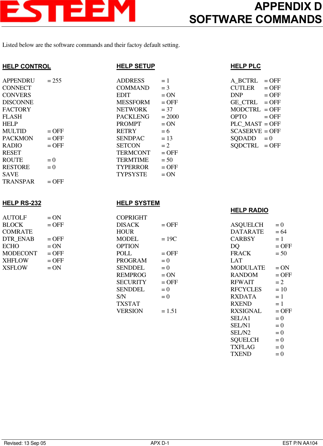
![APPENDIX DSOFTWARE COMMANDSRevised: 13 Sep 05 APX D- 6EST P/N AA104MESSform (on/off)When enabled all of the system status and error messages will be in a formatted form."xx" indicates what error or message (See Error Messages and System Status Messages).EMxx <CR> [ESTeem Error Messages]SExx <CR> [System Error Messages]SSxx <CR> [System Status Messages]SSxx-xxxx <CR> [System Status Message W/Returned Value]ON: Enabled.OFF: Disabled.Factory default = OFF.MOdecontr (on/off)ON: The mode of the ESTeem modem is controlled by pin 19 of the RS-232C connector. A low (0) directs the ESTeem intothe COMMAND mode. A high (1) directs the ESTeem into CONVERSE/TRANSPARENT mode.OFF: The mode of the ESTeem modem is controlled by ASCII character.Factory default = OFFMODEL (xx)Displays the product model of default firmware that is installed. Model should be the same as product being used. Listed beloware the model codes19C = ESTeem Model 192C19F = ESTeem Model 192F19V = ESTeem Model 192VMODCTRLThis command enables the Modicon controller protocol. For further detail Reference the EST Engineering Report on Modiconcontroller interfacing. OFF: Disabled.Factory default = OFF.MODUlate (on/off)The radio modulate command. When enabled will transmit a modulated test signal when the RADIO ON command is enabled.ON: Enabled.OFF: Disabled.Factory default = OFF.MOORE (on/off)This function enables the Moore products using Hart protocol. For further details reference the EST Engineering Report onMoore Products interfacing. ON: Enabled.OFF: Disabled.Factory default = OFF.](https://usermanual.wiki/Electronic-Systems-Technology/ESTEEM192MHP.Manual-Part-2/User-Guide-599036-Page-30.png)
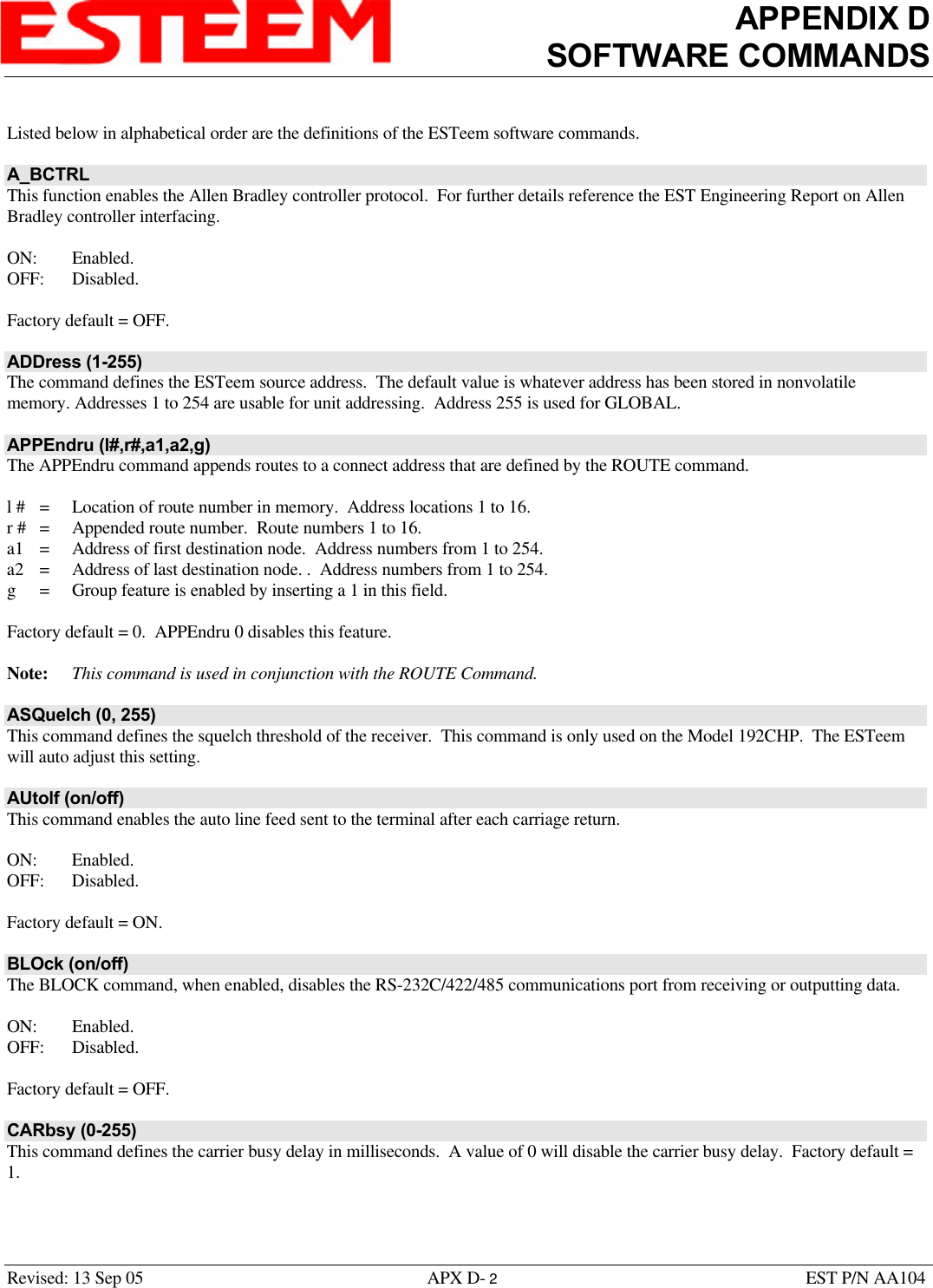
![APPENDIX DSOFTWARE COMMANDSRevised: 13 Sep 05 APX D- 7EST P/N AA104MULTID (on/off)This command when enabled allows the ESTeem User to send data to another ESTeem from the CONVERSE MODE byspecifying the routing address before the data.ON: Enabled.OFF: Disabled.Factory default = OFF.Example Of Transmitted Data:[001]DATA Routes data to an ESTeem addressed 1.[100,200,250,1]DATA Routes data to an ESTeem addressed 1 via ESTeems addressed 100, 200, and 250.This replaces using the CONNECT command from the COMMAND Mode. Received data packets will have the address of theESTeem that sent the data at the beginning of the data packet.Example Of Received Data:[004]RECEIVED DATA Data received from an ESTeem addressed 4.[030,100,244,004] Data received from an ESTeem addressed 4 via ESTeems addressed 30, 100, and 244.NETwork (0-255)Network identification code. This is used to program a common code for all modems in the customers network so that anotherfacility on your frequency using the same addresses will not interfere with your equipment. Factory default = 37.OPTO (on/off)This function enables the Opto 22 protocol. For further details reference the EST Engineering Report on Opto 22 interfacing. ON: Enabled.OFF: Disabled.Factory default = OFF.PACKleng (1-2000)This command defines the length of the data packet in bytes. Factory default = 2000.PACKMon (on/off)Places the ESTeem in the packet monitor mode. Factory default = OFF.PHone (on/off)Phone port enable command. The ESTeem will answer an incoming call when enabled.ON: Enabled.OFF: Disabled.Factory default = OFF.](https://usermanual.wiki/Electronic-Systems-Technology/ESTEEM192MHP.Manual-Part-2/User-Guide-599036-Page-31.png)