Electronic Systems Technology ESTEEM195C 450-470MHz Narrow-band UHF modem User Manual ESTEEM USERS MANUAL
Electronic Systems Technology 450-470MHz Narrow-band UHF modem ESTEEM USERS MANUAL
Contents
- 1. User Manual Part 1
- 2. User Manual Part 2
User Manual Part 1

ESTeem USER’S MANUAL
Models 195C – 195M
Manual Revision 1.0
September 2013
Electronic S
y
stems Technolo
gy,
Inc.

Author: Date:
Name: Eric P. Marske
Title: Product Support Manager
Approved by: Date:
Name: Tom L. Kirchner
Title: President
Electronic Systems Technology, Inc.
Building B1
415 N. Quay Street
Kennewick, WA 99336
Phone: 509-783-9092
Fax: 509-783-5472
E-mail: market@esteem.com
Web Site: www.esteem.com
Copyright© 2013 by Electronic Systems Technology, Inc.
All rights reserved. Printed in the United States of America. No part of this publication may be reproduced, stored
in a retrieval system, or transmitted, in any form or by any means, electronic, mechanical, photocopying, recording,
or otherwise, without the prior written permission of Electronic Systems Technology.

PRODUCT WARRANTY
ELECTRONIC SYSTEMS TECHNOLOGY, INC. Specifications subject to change without notice
415 North Quay Street • Kennewick, WA 99336 www.esteem.com
Phone (509) 735-9092 • Fax (509) 783-5475 Revised: 26 September 2013
Electronic Systems Technology, Inc., (hereinafter EST) expressly warrants its products as free of manufacturing defects for a period
of one year from the date of sale to first user/customer. THERE ARE NO OTHER WARRANTIES, EXPRESS OR IMPLIED AND
THERE IS EXPRESSLY EXCLUDED ALL WARRANTIES OF MERCHANTABILITY OR FITNESS FOR A PARTICULAR
PURPOSE. NO OTHER WARRANTY GIVEN BY ANY EMPLOYEE, AGENT, DISTRIBUTOR OR OTHER PERSON WITH
RESPECT TO THE PRODUCT SHALL BE BINDING ON EST.
LIMITATION OF LIABILITY:
EST's liability shall be limited to refunding of purchase price, repair or replacement of product. IN NO EVENT SHALL EST HAVE
LIABILITY FOR CONSEQUENTIAL, INCIDENTAL, SPECIAL OR EXEMPLARY DAMAGES CAUSED DIRECTLY OR
INDIRECTLY BY THE PRODUCT, INCLUDING BUT NOT LIMITED TO ANY INTERRUPTION OF SERVICES, LOSS OF
BUSINESS OR ANTICIPATORY PROFITS. IN NO EVENT SHALL EST BE LIABLE FOR ANY DAMAGES WHATSOEVER IN
EXCESS OF THE PURCHASE PRICE OF THE PRODUCT.
In the event that a unit or part requires replacement or factory servicing, the following conditions apply:
a) Customer must obtain from EST an authorized RMA (Return Materials Authorization) Number before shipment of product
or parts to EST for any reason;
b) If the whole unit is shipped, it must be in its original carton and shipping components, or a carton and shipping components
supplied by EST, or it parts only are shipped, they must be packaged and cushioned so as to prevent damage in transit
and shipped freight prepaid;
PRODUCT WILL BE CONSIDERED OUT OF WARRANTY IF:
a) If the product is damaged due to improper or abnormal use, abuse, mishandling, accident or improper maintenance or
failure to follow operating instruction;
b) If the product is defective as a result of sand, dirt, or water damage;
c) If any factory-sealed enclosure has been opened or shows evidence of an attempt to be opened;
d) If defects or damage are caused by the use of unauthorized parts or unauthorized service;
e) If the product has had its serial numbers altered or removed.
Warranty repair form must be accompanied by proof of user's purchase of unit. Product must be shipped to the manufacturer at the
following address:
Electronic Systems Technology
415 North Quay Street
Kennewick, Washington USA 99336
ADDITIONAL SERVICE:
If EST releases an improvement update to firmware internal to the ESTeem unit during the 90 day period after the unit was
purchased by the first user/customer, EST will update the applicable unit with the revised version at no charge other than for UPS
handling and shipping to and from your location to the EST factory. Return of any such item must be accompanied with proof of
purchase.

TABLE OF CONTENTS
Revised: 26 Sep 13 Page 1 EST P/N AA107-195C/MCM
CHAPTER 1 – Introduction
Before You Begin 1-1
Model 195C/M Overview 1-1
Model 195C/M Configuration Modes 1-1
Access Point Modes --------------------------------------------- 1-2
Access Point Repeater --------------------------------------------- 1-3
Self-Healing Mesh Network --------------------------------------------- 1-3
Station Modes --------------------------------------------- 1-4
RS-232 Serial Applications --------------------------------------------- 1-5
CHAPTER 2 – Starting Out
Three Configuration Phases 2-1
Model 195C/M Hardware Description 2-1
Front Panel Layout --------------------------------------------- 2-2
Antenna Connection Overview --------------------------------------------- 2-2
CHAPTER 3 – Example Applications
Modes of Operation Description and Examples 3-1
Ethernet Bridge Mode --------------------------------------------- 3-1
Router Modes --------------------------------------------- 3-3
Mobile Client Modes --------------------------------------------- 3-4
Programming Examples 3-7
Using ESTeem Network Configuration (ENC) Utility --------------------------------------------- 3-7
Example 1 – Point to Point Ethernet Bridge --------------------------------------------- 3-9
Example 2 – Point to Point Ethernet Bridge with Repeater --------------------------------------------- 3-10
Example 3 – Point to Multipoint with Mesh Repeater --------------------------------------------- 3-11
Example 4 – Point to Multipoint Router Mode --------------------------------------------- 3-13
Example 5 – Mobile Client Mode --------------------------------------------- 3-15
Example 6 – Access Point Mode --------------------------------------------- 3-16
Router Addressing Examples --------------------------------------------- 3-17
CHAPTER 4 – Utilities and Features
ESTeem Network Configuration (ENC) Utility --------------------------------------------- 4-1
Using ESTeem Discovery Program --------------------------------------------- 4-2
Using EtherStation Status Program --------------------------------------------- 4-5
Setting Local Time 195C/M --------------------------------------------- 4-6
Configuring Time Server --------------------------------------------- 4-7
Simple Network Management Protocol (SNMP) --------------------------------------------- 4-15

TABLE OF CONTENTS
Revised: 26 Sep 13 Page 2 EST P/N AA107-195C/MCM
CHAPTER 5 – Web Configuration
Logging Into Web Configuration Manager 5-1
Web Configuration Manager 5-2
Top Menu --------------------------------------------- 5-2
Setting ModemID Field --------------------------------------------- 5-2
Status Menu --------------------------------------------- 5-3
System Log Screen --------------------------------------------- 5-5
Setup Screen --------------------------------------------- 5-5
Advanced Configuration Screen --------------------------------------------- 5-6
Backup Screen --------------------------------------------- 5-6
Restore Screen --------------------------------------------- 5-7
Software Update --------------------------------------------- 5-8
System Reboot --------------------------------------------- 5-8
CHAPTER 6 – Serial Configuration and Applications
Using USB Programming Port 6-1
Using RS-232 Data Port 6-3
CHAPTER 7 – Repeating and Mesh Networking
ESTeem Mesh Network 7-1
Configuration --------------------------------------------- 7-1
Rapid Spanning Tree Protocol (RSTP) 7-2
Spanning Tree Protocols (STP) 7-3
Overview --------------------------------------------- 7-3
Phases --------------------------------------------- 7-4
Priority and Path Cost --------------------------------------------- 7-4
Root Bridge --------------------------------------------- 7-4
Redundant Backup 7-5
Redundant Master Configuration --------------------------------------------- 7-5
CHAPTER 8 – Antenna Setups
Antenna and Cable Configurations 8-1
Weatherproofing Coaxial Cable Connections 8-6

TABLE OF CONTENTS
Revised: 26 Sep 13 Page 3 EST P/N AA107-195C/MCM
APPENDIX A – FCC Information
APPENDIX B – Interface Ports
Ethernet Interface --------------------------------------------- B-1
RS-232 Data Port Pin-Out --------------------------------------------- B-1
APPENDIX C – Radio Configuration
Frequency of Operation --------------------------------------------- C-1
Average RF Output Power --------------------------------------------- C-1
APPENDIX E – Troubleshooting
Testing Communication Link --------------------------------------------- D-1
Viewing RF Data Rates --------------------------------------------- D-3
Signal Strength vs Data Rates --------------------------------------------- D-4
Setting Maximum Distance Value --------------------------------------------- D-4
Troubleshooting Tips --------------------------------------------- D-5
APPENDIX F – 195C/M Specifications
195C/M Specifications --------------------------------------------- E-1
Case Layout --------------------------------------------- E-2
Antenna Specifications --------------------------------------------- E-3
CHAPTER 1
INTRODUCTION
BEFORE YOU BEGIN
Thank you and congratulations on your purchase of the ESTeem Model
195C/M Wireless Ethernet Radio Modem! This manual was written to help
both the first time and advanced user of the 195C/M to configure the
wireless modem for your application. If this is your first time configuring
the 195C/M and you would like to get going as soon as possible, we
recommend using the ESTeem Resource CD provided with the modem. The
Resource CD will provide the software utilities and guide you through the
configuration of the wireless modem for your application. Figure 1: ESTeem Model 195C/M Series
The ESTeem 195C/M wireless Ethernet modems are sophisticated networking devices. To keep the manual usably short,
many of the application descriptions and programming details assume the user has a good working knowledge of the following
network concepts:
Throughout this User’s Manual are
“Technical Tips” in boxes like this that
have been added to help answer the
most commonly asked questions.
• General Ethernet networking and the configuration of LAN topologies
• Common Ethernet terminology and acronyms
• TCP/IP network protocol structure and how to configure TCP/IP networks
and subnets
• How to identify and set the TCP/IP address on your computer
• Have administrator privileges to the computer and network you are configuring
• If using routing protocols, you must be able to identify and configure the network routers, gateways and firewalls
• You must be familiar with using web browser software such as Internet Explorer, Chrome or Firefox
If you are unfamiliar with any of the above networking concepts, you may need to contact your network administrator for
assistance.
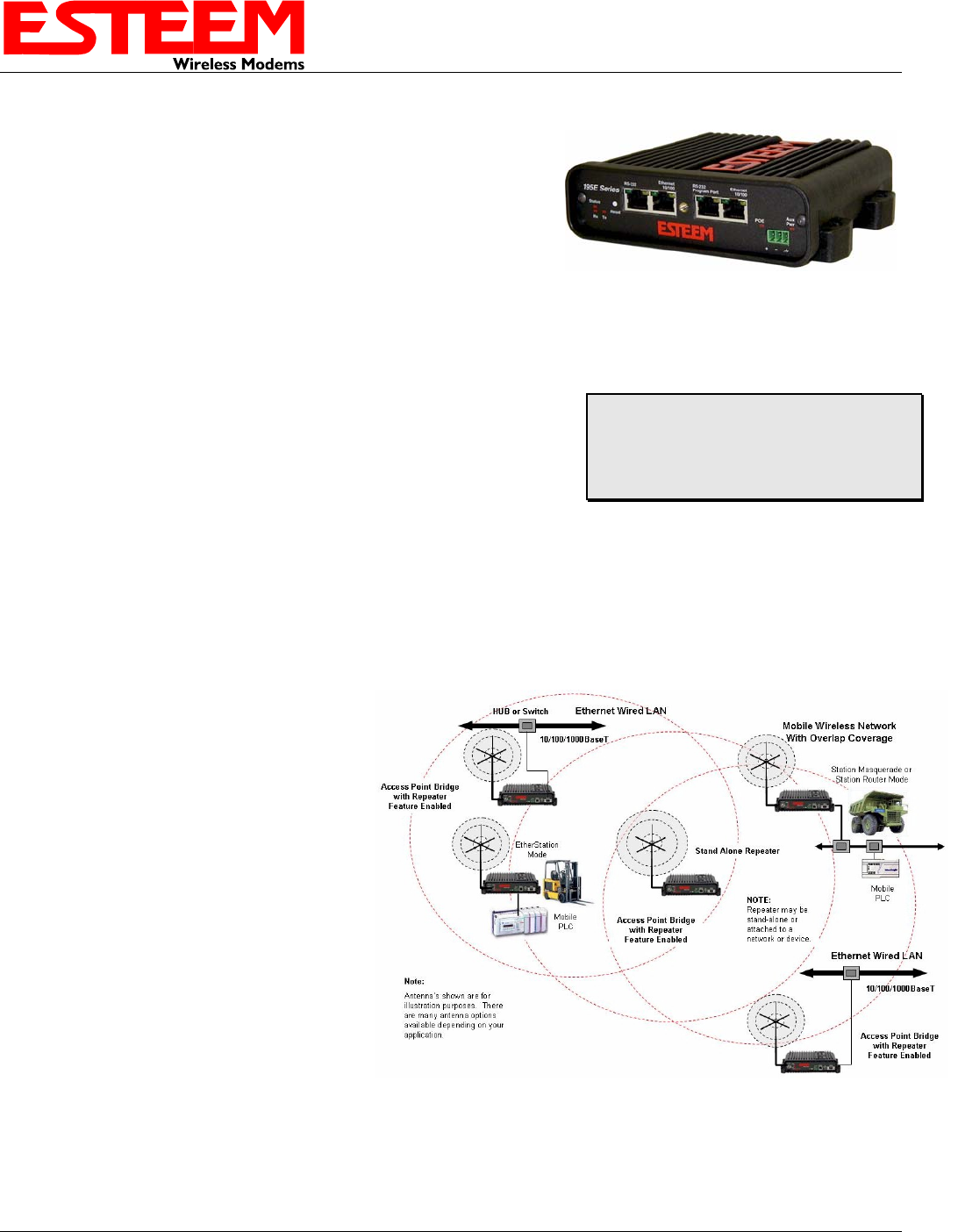
MODEL 195C/M OVERVIEW
Figure 2: Access Point Bridge Diagram
The ESTeem Model 195C/M and 195C/M are
wireless modem transceivers that can be used to
build many types of Wireless Local Area
Networks (WLAN). The ESTeem 195C/M series
have both and Ethernet interface and an RS-232
serial port for legacy device networks. The Model
195C/M is a very sophisticated networking device
that can be configured for multiple modes of
operation depending upon the needs of the
wireless and wired LAN system. The following
configuration modes are provided as an overview
of the basic network types, as all possible network
configurations can not be listed. For further help
in selecting the correct network type, please refer
to Chapter 4 of this User’s Manual or call
Customer Support at 509-735-9092.
Revised: 1 Oct 13 1-1 EST P/N AA107-195CM
CHAPTER 1
INTRODUCTION
Revised: 1 Oct 13 1-2 EST P/N AA107-195CM
CONFIGURATION MODES
A Model 195C/M can be configured for
multiple modes of operation without any
changes to the hardware. The following are
brief descriptions of the configuration modes.
For detailed descriptions and suggested
applications for each mode, please refer to
Chapter 4.
Access Point Bridge Mode
When a Model 195C/M is configured as an
Access Point Bridge it will provide a wireless
bridge for mobile clients. Multiple Access
Points can be physically connected to the same
network (LAN) or through a radio link using
the Access Point Repeater mode to provide
overlapping, seamless Ethernet communication
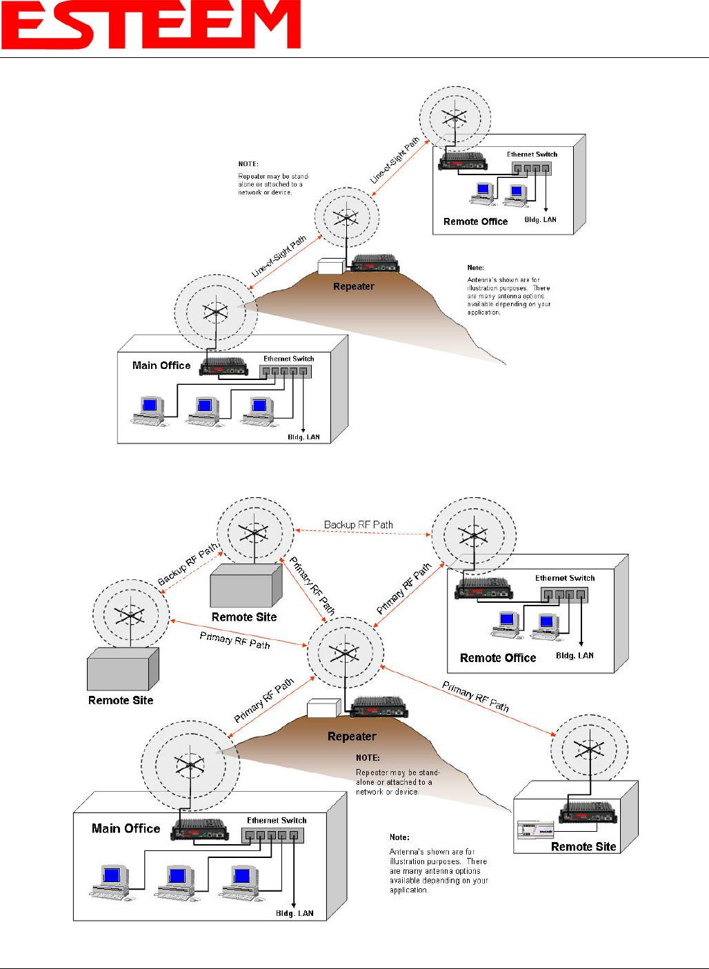
for mobile devices. Figure 3: Repeater Mode Diagram
An ESTeem Model 195C/M in Access Point Bridge mode will both provide wireless access to mobile clients (Access Point) and
bridge all Ethernet data connected to the Ethernet ports. The AP Bridge mode will pass all network traffic between connected
devices including global network broadcasts. (See Figure 2).
Repeater Mode
The Repeater Mode can be used with any of the above Access Point modes. With this repeater feature enabled, the Model
195C/M Access Points do not have to be hardwired together on the same physical LAN to provide seamless Ethernet
communication for roaming clients. In addition to greatly extending the Access Point canopy range, the Model 195C/M will also
bridge any Ethernet device or Ethernet network connected to the unit over this same wireless Ethernet network. This mode gives
the user the features of a point to multi-point bridge network but also allows the Model 195C/M in the Client mode to
simultaneously roam under the network canopy.
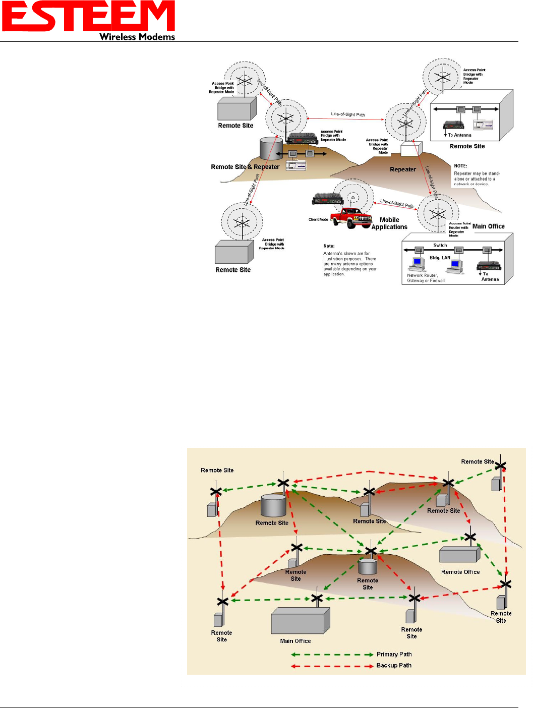
Self-Healing Mesh Network
If multiple repeater routes are configured
to the same destination ESTeem, the
195C/M will create a “self-healing” mesh
network by automatically re-routing data
through alternate paths to reach its
destination if the primary path is
inoperable. The routing and priority of
alternate paths is completely user
configurable. (See Figure 5)
Figure 5: Mesh Network Diagram
CHAPTER 1
INTRODUCTION
EtherStation (Client) Mode
When the 195C/M is configured in the EtherStation mode and attached to a single Ethernet Device, the Model 195C/M will
emulate a wireless card in functionality for communication as a mobile client. The 195C/M will seamless roam under the radio
canopy of Access Points and can provide wireless communication for mobile Ethernet devices such as vehicles, forklifts, cranes,
etc (Figures 2&3).
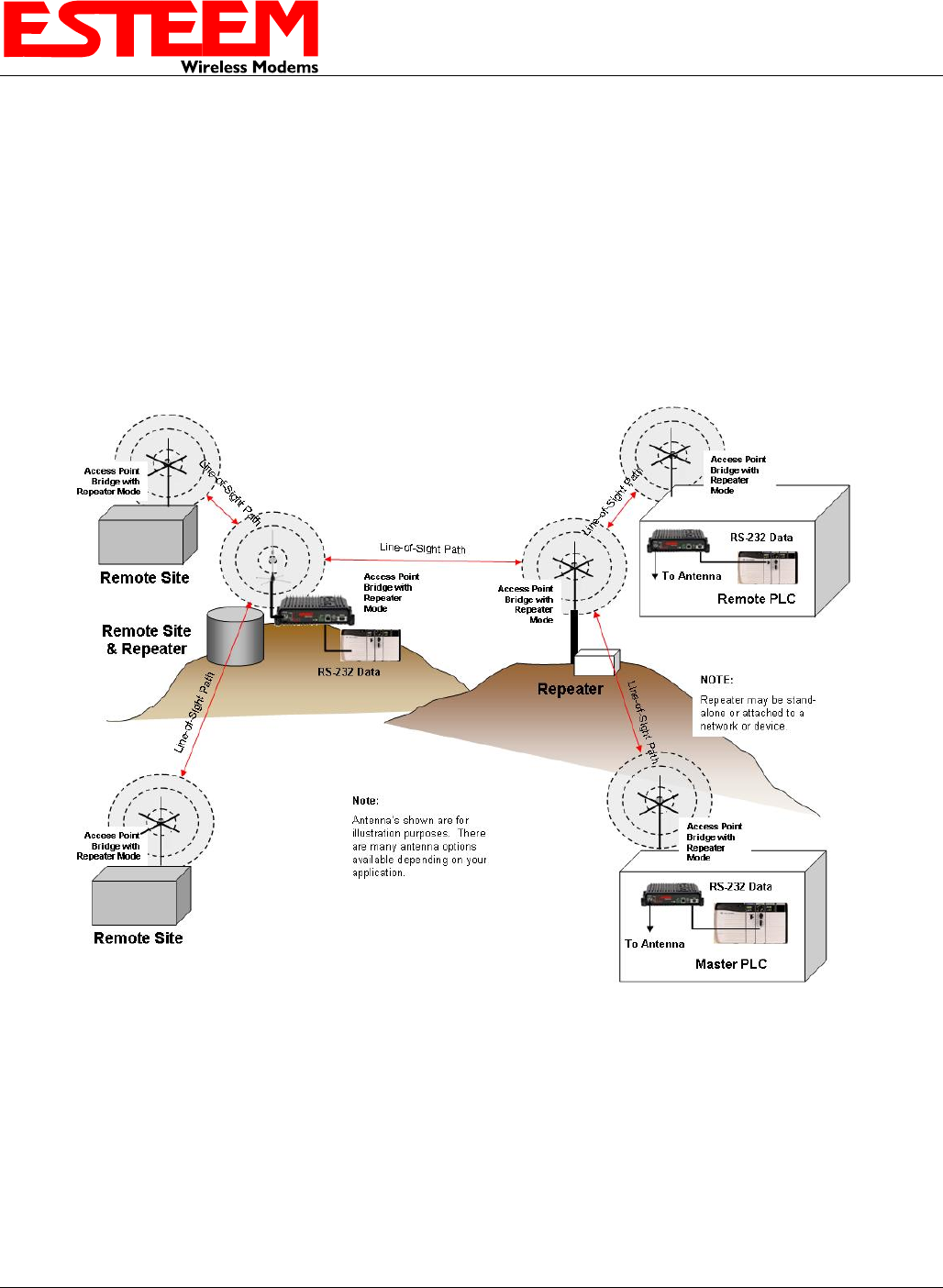
RS-232 Serial Applications
The ESTeem 195C/M is installed with an RS-232 data port for serial data applications run over the wireless links (Figure 6). The
serial network can be used in a point-to-point or point-to-multi-point application for networking serial (RS-232C) devices,
providing serial connections to legacy hardware in a new Ethernet network.
Figure 6: Multi-point Serial Diagram
To begin setup of your wireless Ethernet network, continue to Chapter 2 - Staring Out of this User’s Manual.
Revised: 1 Oct 13 1-3 EST P/N AA107-195CM

CHAPTER 2
STARTING OUT
Revised: 1 Oct 13 2-1 EST P/N AA107-195CM
OVERVIEW
There are three main phases to prepare the ESTeem 195C/M for operation in a wireless network:
Phase 1 - Determine the correct mode of operation for the ESTeem in the wireless network. The ESTeem 195C/M is a
sophisticated networking device that can be configured for multiple modes of operation. Determining the correct mode of
operation for the ESTeem 195C/M is the first step. Chapter 3 of this User’s Manual details the modes of operation and
applications where each would be used.
Phase 2 - Program the ESTeem for operation in the wireless network. Once the correct mode of operation for the ESTeem
has been determined, the 195C/M can be programmed for the wireless network. To simplify the programming of the Model
195C/M, ESTeem has created a new software utility called the ESTeem Network Configuration (ENC) Utility which is used to
graphically configure the primary and backup communication routes between ESTeem 195C/M’s in the network. The ENC
Utility can be installed from the ESTeem Resource Disk or from the ESTeem web site (www.esteem.com). Chapter 4 (Utilities
and Features) of this User’s Manual will guide you in the installation of the software and give a brief overview of operation of the
ENC Utility, but a detailed User’s Guide is available both on the ESTeem Resource Disk and in the Help section of the program
itself.
The ESTeem Model 195C/M can also be programmed through the internal Web interface (discussed in detail in Chapter 5) if you
do not have access to the ENC Utility.
Phase 3 - Install the ESTeem hardware and test communication. After the ESTeem Model 195C/M’s programming, install
the hardware in each remote location. Chapter 8 of this User’s Manual describes the antenna specifications, mounting options and
the configuration of the pole mounting hardware for the ESTeem. For instructions on testing and troubleshooting the wireless
link, refer to Appendix F (Troubleshooting).
MODEL 195C/M HARDWARE LAYOUT
To begin the configuration, unpack the ESTeem Model 195C/M shipping boxes and locate the items below for initial
configuration. Take a few minutes to inventory your equipment before you proceed. Report any missing or damaged items to
Customer Support (509-735-9092) as soon as possible. Each node in your ESTeem Model 195C/M’s network may have different
hardware components based upon the final installation location (i.e. Outdoor, Indoor, Point-to-point or Muti-Point). Antenna
types, cable lengths, power supplies may be different, but the following items will be required for basic setup:
Model 195C/M
AA109 Resource Disk
Antenna
(AA20C.1 Displayed)
Coax Cable
(Antenna to ESTeem
195C/M)
Power Supply
(AA174 Displayed)
Ethernet Cable

CHAPTER 2
STARTING OUT
Revised: 1 Oct 13 2-2 EST P/N AA107-195CM
Note: Your accessory model numbers may vary from the above, but you will need to locate each of above items to continue
configuration.

CHAPTER 2
STARTING OUT
Revised: 1 Oct 13 2-3 EST P/N AA107-195CM
MODEL 195C/M HARDWARE CONFIGURATION
Technical Tips:
1. Configure the Model
195C/M prior to
mounting.
2. Attach antenna to the
Model 195C/M before
powering up.
The following steps should be completed to begin configuration of the ESTeem Model 195C/M:
1. Connect the antenna to the TNC connection on the ESTeem Model 195C/M (Figure 1).
2. Connect the power supply and Ethernet cable to the ESTeem and proceed to Chapter 3 to
begin programming.
CHAPTER 3
EXAMPLE APPLICATIONS
MODES OF OPERATION
The ESTeem Model 195C/M is a sophisticated wireless networking device that can be configured for multiple modes of
operation. Determining the correct mode of operation for the ESTeem is the first step in creating a reliable wireless network.
This chapter will explain each mode of operation, provide example applications and detailed programming information for
each mode. Please review the following modes of operations. If you do not see an example of your application, please contact
ESTeem support at 509-735-9092 for help in selecting your mode of operation.
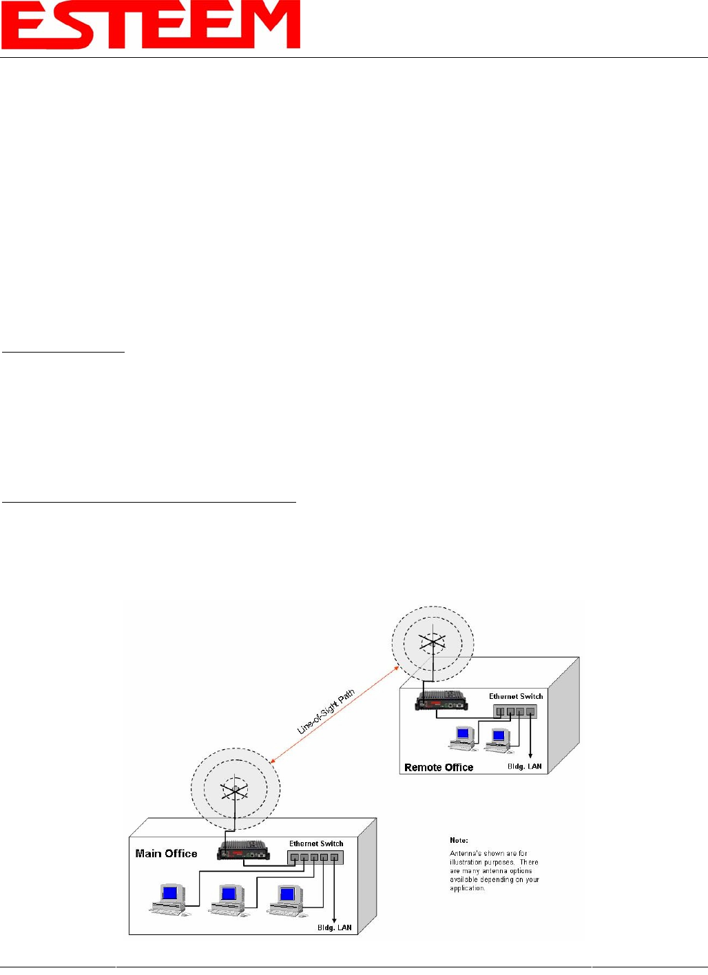
Ethernet Bridge Mode (AP Bridge)
The most commonly used mode of operation with the ESTeem Model 195C/M is the Ethernet bridge mode. The Ethernet
bridge mode will connect two or more ESTeem 195C/M’s while passing all network traffic that arrives in both the wireless and
connected Ethernet ports; including all global network traffic (Figure 1). This mode will work in most wireless applications of
the 195C/M to wirelessly connect two or more remote Ethernet devices or networks. The Ethernet bridge mode is also used in
repeating (Figure 2) and in self-healing Mesh networks (Figure 3) for fixed (non mobile) applications.
Example Applications
• Building to building remote wireless LAN networks
• Point to point wireless Ethernet communication devices
• Multi-point wireless Ethernet networks
• Remote Supervisory Control and Data Acquisition (SCADA) networks
• Redundant, self-healing Mesh networks
• Fixed locations with mobile ESTeem 195C/M’s
Applications Where Ethernet Bridge Mode Not Used
• Mobile applications (see Mobile Clients)
• Connections to large Ethernet traffic networks such as large office buildings or plant networks (see Router modes)
Revised: 1 Oct 13 3-1 EST P/N AA107-195CM
Figure 1: Point to Point Example
CHAPTER 3
EXAMPLE APPLICATIONS
Figure 2: Ethernet Bridge with Repeater
Figure 3: Multipoint Bridge with Mesh Networking
Revised: 1 Oct 13 3-2 EST P/N AA107-195CM
CHAPTER 3
EXAMPLE APPLICATIONS
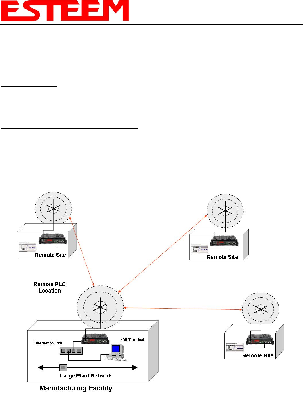
Router Modes (AP Router and AP Masquerade)
The ESTeem 195C/M can be configured as a network router or network firewall between the Ethernet LAN connection and the
wireless network of remote locations. The router modes are used to limit the network traffic from a busy Ethernet network
connection to only those specific IP address used on the wireless network (see Figure 4). The Ethernet router mode (AP
Router) will allow bi-directional communication from the Ethernet LAN connection to the wireless network.
Example Applications
• Wireless Ethernet networks connected to large company or plant Ethernet LAN networks (AP Router)
• Wireless Ethernet networks with a requirement for network isolation from the plant or company network (AP Router)
• Shared Ethernet connection to direct Internet service (DSL, Cable, T1, etc.) (AP Masquerade)
Applications Where Ethernet Router Mode Not Used
• Mobile applications (see Mobile Clients)
• Simple network connections only using a single IP network subnet (see Ethernet Bridge modes)
Figure 4: Router Mode Example
Revised: 1 Oct 13 3-3 EST P/N AA107-195CM
CHAPTER 3
EXAMPLE APPLICATIONS
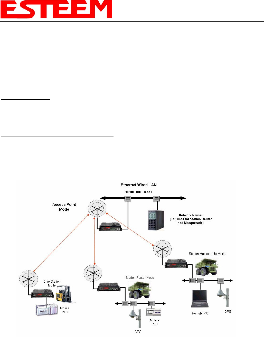
Mobile Client Modes (EtherStation, Station Router or Station Masquerade)
The ESTeem 195C/M can also be configured to function as a mobile client. The client modes allow the 195C/M to seamlessly
roam between fixed Access Points. The client modes will allow mobile Ethernet devices to connect to each other or to an
Ethernet LAN through the fixed AP (Figure 5).
The EtherStation mode is used to connect a single Ethernet device to the ESTeem 195C/M. If you are connecting the 195C/M
to multiple Ethernet devices in a mobile mode, the Station Router or Station Masquerade will be required. The Station Router
will allow bi-directional communication between the Ethernet devices connected to the 195C/M and the wireless network,
while the Station Masquerade will serve as a firewall on the Ethernet side.
Example Applications
• Mobile applications where the 195C/M will change links often between fixed Access Points
• Long range mobile client networks
• Public safety applications for police, fire and EMS
Applications Where Mobile Client Mode Not Used
• Fixed locations using Ethernet Bridging or Routing
• Wireless Ethernet networks with repeaters
• Mobile applications
Figure 5: Router Mode Example
Revised: 1 Oct 13 3-4 EST P/N AA107-195CM
CHAPTER 3
EXAMPLE APPLICATIONS
PROGRAMMING EXAMPLES
Once the mode of operation for the ESTeem has been determined, you
are now ready to program the Model 195C/M for use. ESTeem has
created a simplified network programming utility call the ESTeem
Network Configuration (ENC) Utility. This ENC Utility will be used
in all the following programming examples. For detailed instructions
on installing the ENC Utility, please refer to the User’s Guide (found in
the ESTeem Resource CD or Utility program itself) or Chapter 4 of this
User’s Manual.
Technical Tip: The ENC Utility calculates the
wireless link information based upon exact
ESTeem serial numbers. The serial numbers
listed in the following examples are for example
only. Enter the correct ESTeem serial numbers
for your application.
Adding ESTeems to ENC Utility and Changing Name
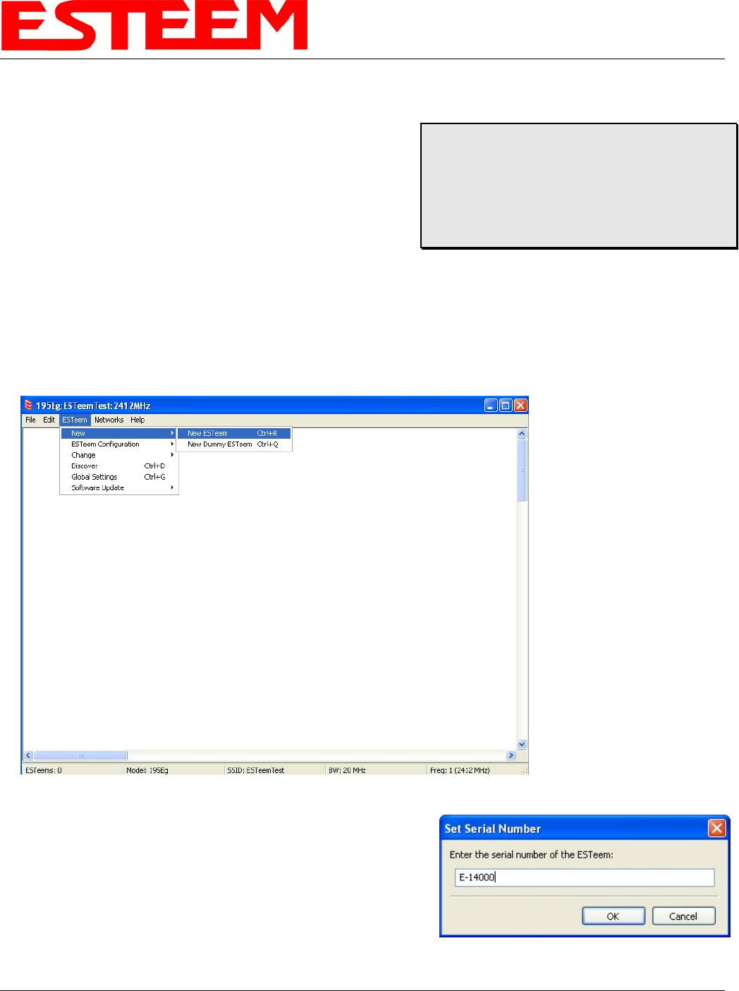
Each of the example applications will use the following procedure to add and rename ESTeem 195C/M’s.
1. Consult the ENC Utility’s User Guide on how the create a new wireless network. Once you have a blank network
configuration page (Figure 9), select ESTeem from the menu items to display the drop down menu, then select New>New
ESTeem.
Figure 9: Adding ESTeem to Blank ENC Configuration Page
2. Enter in the ESTeem Model 195C/M serial numbers used for the
example (for example enter E-14000 in the Set Serial Number Box)
and press the OK button (Figure 10). The ENC Utility will look up
the ESTeem 195C/M’s serial number in the database and match the
correct Wireless LAN MAC (WLAN MAC) address to the modem.
This WLAN MAC address will be displayed above the modem
symbol on the screen (Figure 11).
Figure 10: Enter the Serial Number
Revised: 1 Oct 13 3-5 EST P/N AA107-195CM
CHAPTER 3
EXAMPLE APPLICATIONS
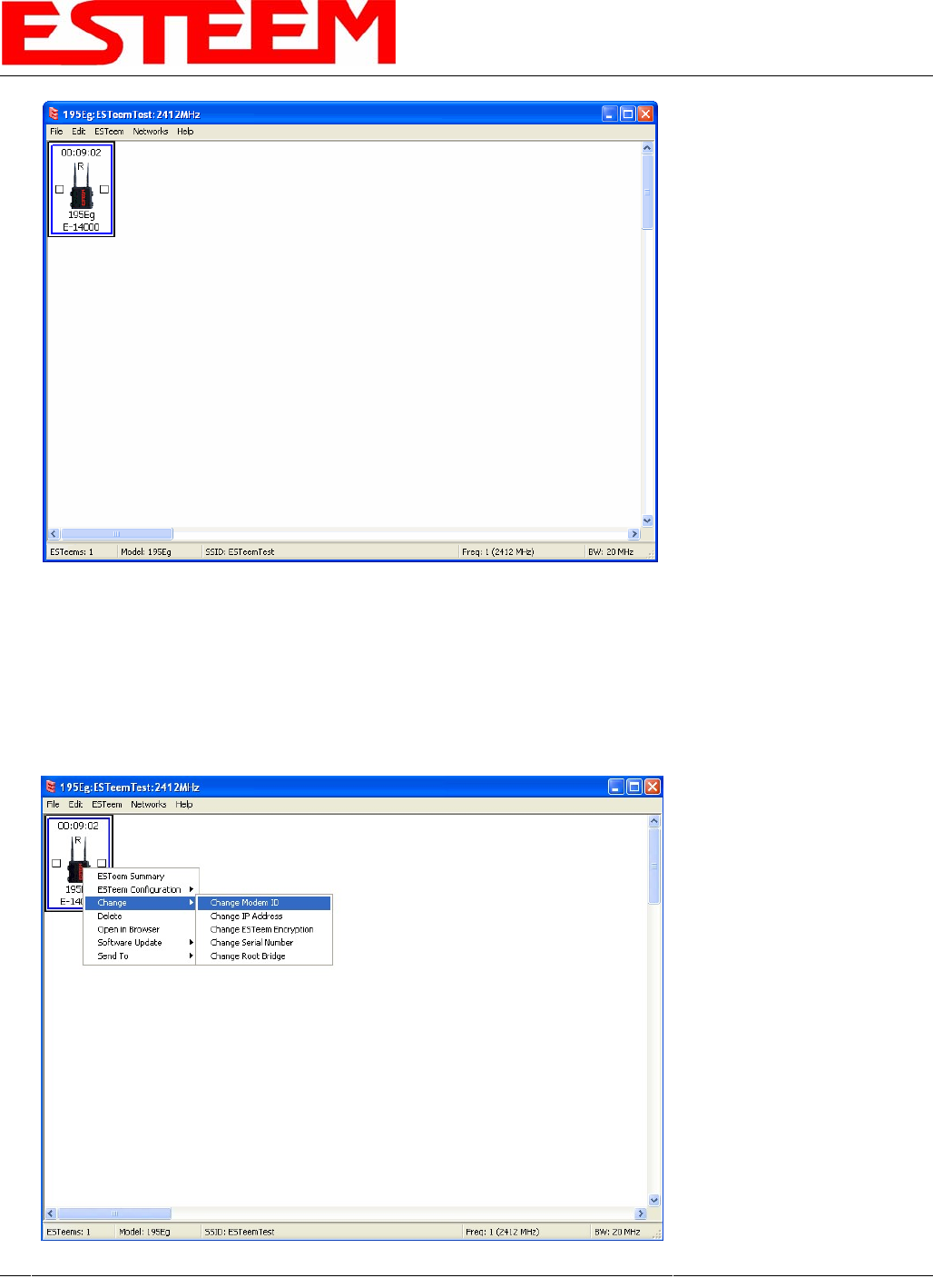
3. To change the name of the ESTeem 195C/M from the WLAN MAC address to “Main Office” (or any other location
name) to match the example configuration, Right-Mouse click on the ESTeem icon and select Change>Change Modem
ID (Figure 12). Enter “Main Office” in the pop-up window and select OK.
Figure 11: Main Office ESTeem 195C/M
4. Duplicate the above procedure for each ESTeem 195C/M added to the network.
Revised: 1 Oct 13 3-6 EST P/N AA107-195CM
Figure 12: Change Modem ID
CHAPTER 3
EXAMPLE APPLICATIONS
Ethernet Bridge Mode Example 1 (Figure 1)
Point to Point Ethernet Bridge
(2) ESTeem Model 195C/M
Serial Numbers: E-14000 (Main Office) and E-14001 (Remote Office)
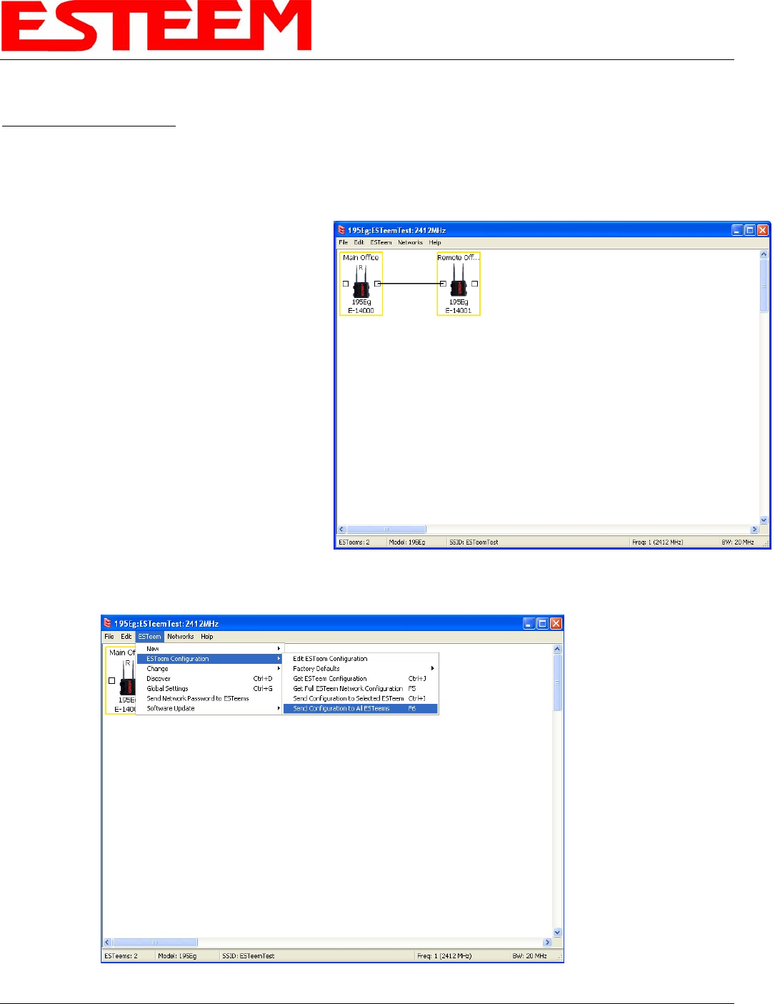
1. Add the two ESTeem Model 195C/Ms to the network using the above procedure. Once both ESTeem 195C/Ms are on
the configuration page, create a wireless link by
clinking on one of the two connection boxes and
dragging a line to the other modem (Figure 13).
Revised: 1 Oct 13 3-7 EST P/N AA107-195CM
5. Verify both ESTeem modems are connected to
the same switch as the computer running the
ENC Utility and send the configuration to both
modems at the same time by selecting
ESTeem>ESTeem Configuration>Send
Configuration to All ESTeems (Figure 14).
6. Once the ENC Utility has downloaded the
configuration for both ESTeem 195C/Ms, the
status box around the ESTeems will change from
yellow to blue. This indicates that the
configuration was completed successfully and
the ESTeem 195C/Ms are ready to be installed
in the application.
Figure 13: Create Wireless Link
Figure 14: Send Configuration to ESTeems
CHAPTER 3
EXAMPLE APPLICATIONS
Ethernet Bridge Mode Example 2 (Figure 2)
Revised: 1 Oct 13 3-8 EST P/N AA107-195CM
Point to Point with Repeater Ethernet Bridge
(3) ESTeem Model 195C/M
Serial Numbers:
E-14000 (Main Office)
E-14001 (Remote Office)
E-14002 (Repeater)
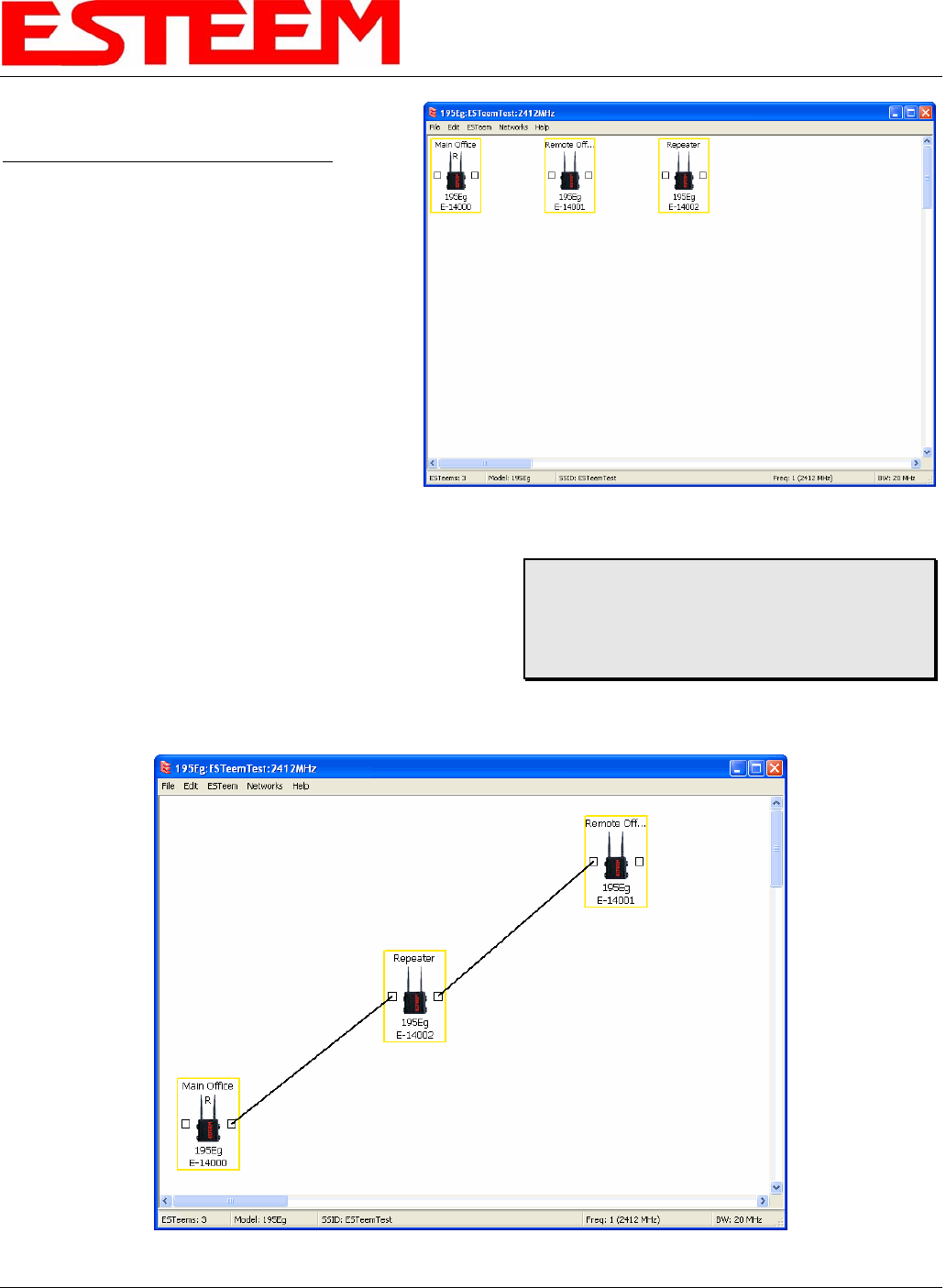
1. Using the above procedure, enter the three
ESTeem 195C/Ms into the ENC Utility. Your
layout should appear like Figure 14.
2. Move the ESTeem 195C/M icons on the screen
to simulate the layout of the diagram. Draw
connection lines between the modems to make
the wireless link in the same order as the
network layout (Figure 15).
3. Verify all ESTeem modems are connected to
the same switch as the computer running the ENC Utility and
send the configuration to both modems at the same time by
selecting ESTeem>ESTeem Configuration>Send
Configuration to All ESTeems. Once the ENC Utility has
downloaded the configuration for both ESTeem 195C/M’s, the
status box around the ESTeem‘s will change from yellow to
blue. This indicates that the configuration was completed
successfully and the ESTeem 195C/M’s are ready to be installed in the application.
Figure 14: Example 2 Modems
Technical Tip: Although it does not matter
where the ESTeem icons are located on the
screen, putting them in the same layout as the
application makes it easier to visually verify the
network connections.
Figure 15: Example 2 Layout
CHAPTER 3
EXAMPLE APPLICATIONS
Ethernet Bridge Mode Example 3 (Figure 3)
Revised: 1 Oct 13 3-9 EST P/N AA107-195CM
Point to Multipoint with Mesh Repeater Links
(6) ESTeem Model 195C/M
Serial Numbers:
E-14000 (Main Office)
E-14001 (Remote Office)
E-14002 (Repeater)
E-14003 (Remote Site 1)
E-14004 (Remote Site 2)
E-14005 (Remote Site 3)
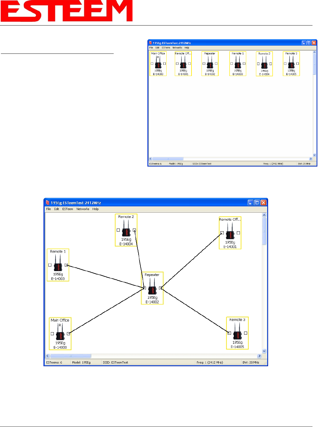
1. Using the above procedure for adding ESTeem
Model 195C/Ms, add the six ESTeem 195C/Ms for
this example and rename by location. Your layout
should appear like Figure 16.
2. Move the ESTeem 195C/M icons on the screen to
simulate the layout of the diagram. Draw
connection lines between the primary wireless
links modems in the same order as the network layout (Figure 17).
Figure 16: Example 3 Modems
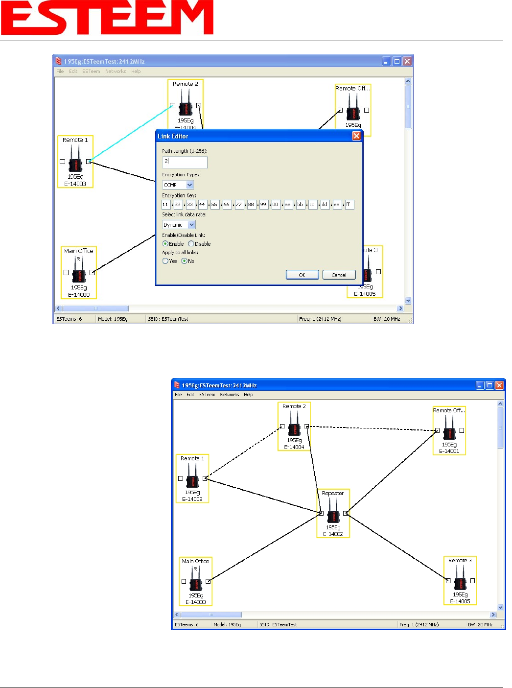
3. To create the backup link between Remote 1 and Remote 2 and the other backup link from Remote 2 to the Remote
Office, draw a wireless connection as you would on the primary link. Double-click on the line created. The Link Editor
box will be displayed (Figure 16). Any Path Length greater than 1 will display as a dashed line indicating a backup link
Figure 15: Example 2 Layout
CHAPTER 3
EXAMPLE APPLICATIONS
in the repeater Mesh configuration (Figure 17). For detailed instruction on Mesh network configuration, refer to Chapter
7 of this User’s Manual.
Figure 16: Backup Link Configuration
4. Verify all ESTeem modems are
connected to the same switch as
the computer running the ENC
Utility and send the configuration
to all modems at the same time
by selecting ESTeem>ESTeem
Configuration>Send
Configuration to All ESTeems.
Once the ENC Utility has
downloaded the configuration for
both ESTeem 195C/M’s, the
status box around the ESTeem‘s
will change from yellow to blue.
This indicates that the
configuration was completed
successfully and the ESTeem
195C/M’s are ready to be
installed in the application.
Figure 17: Mesh Network Configuration
Revised: 1 Oct 13 3-10 EST P/N AA107-195CM
CHAPTER 3
EXAMPLE APPLICATIONS
Ethernet Router Mode Example (Figure 4)
Revised: 1 Oct 13 3-11 EST P/N AA107-195CM
Point to Multipoint Router Mode
(4) ESTeem Model 195C/M
Serial Numbers:
E-14000 (Router at Network)
E-14001 (Remote Site 1)
E-14002 (Remote Site 2)
E-14003 (Remote Site 3)
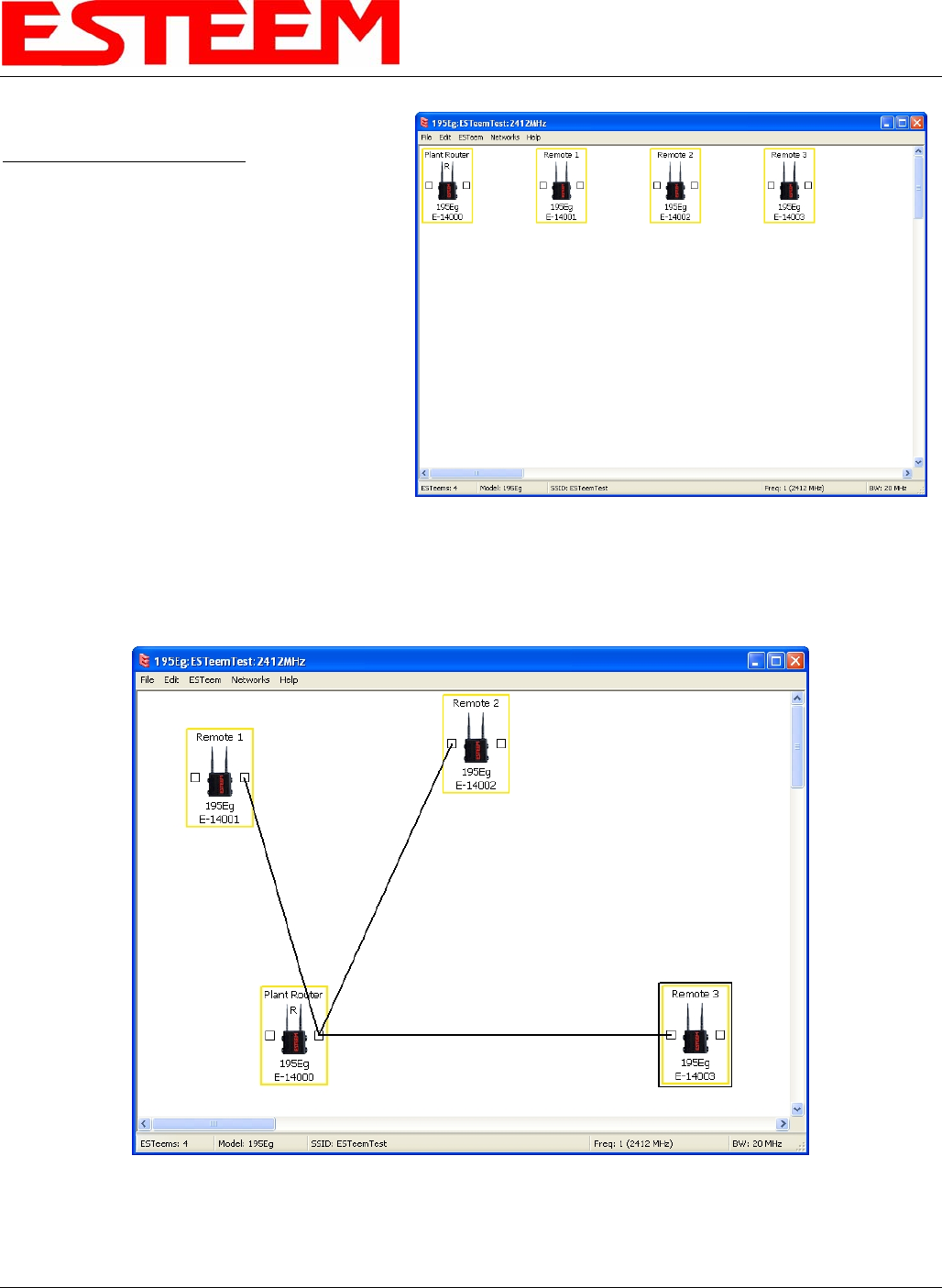
1. Using the above procedure for adding ESTeem
Model 195C/Ms, add the four ESTeem
195C/Ms for this example and rename by
location. Your layout should appear like
Figure 18.
Figure 18: Router Mode Example Modems
2. Move the ESTeem 195C/M icons on the
screen to simulate the layout of the diagram.
Draw connection lines between the wireless
links modems in the same order as the network
layout (Figure 19).
Figure 19: Router Example Layout
CHAPTER 3
EXAMPLE APPLICATIONS
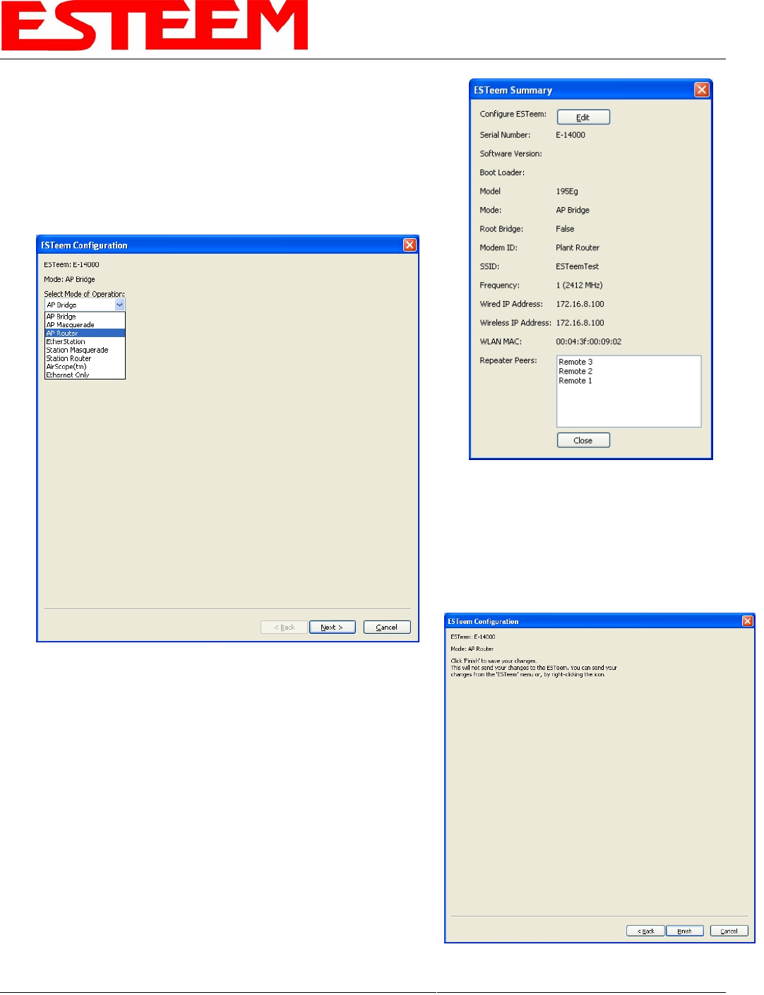
3. By default, the ENC Utility sets all ESTeem modems in AP Bridge
mode. To change the Plant Router ESTeem to AP Router mode, double-
click on the icon to bring up the ESTeem Summary window and press
the Edit button (Figure 20).
Revised: 1 Oct 13 3-12 EST P/N AA107-195CM
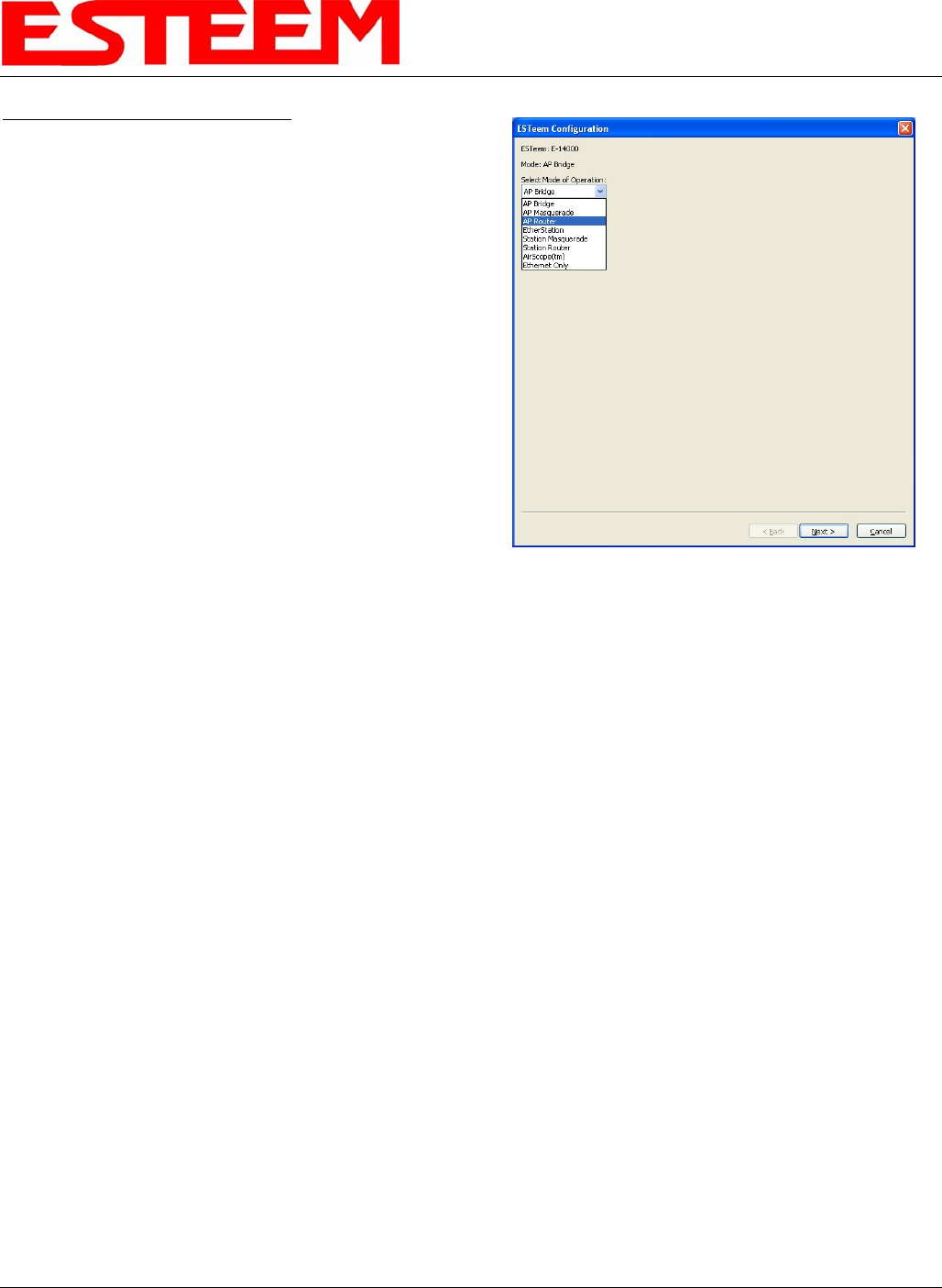
4. Change the Mode of Operation from AP Bridge to AP Router
(or Masquerade if desired) and press the Next button at the bottom of the
window (Figure 21).
Figure 20: ESTeem Summary Page
5. Continue through the configuration screens setting the AP Router
addressing to match the IP address ranges for your network. For
help with setting the router addressing please refer to Router Address
Examples later in this chapter. You will end on the screen in Figure
22. Press the Finish button to return to the configuration page.
Figure 21: AP Router Configuration
6. Verify all ESTeem modems are connected to the same switch as the
computer running the ENC Utility and send the configuration to all
modems at the same time by selecting ESTeem>ESTeem
Configuration>Send Configuration to All ESTeems. Once the ENC
Utility has downloaded the configuration for both ESTeem
195C/Ms, the status box around the ESTeems will change from
yellow to blue. This indicates that the configuration was completed
successfully and the ESTeem 195C/Ms are ready to be installed in
the application.
Figure 22: ESTeem Summary Page
CHAPTER 3
EXAMPLE APPLICATIONS
Mobile Client Mode Example (Figure 5)
EtherStation, Station Router and Station Masquerade Modes
(3) ESTeem Model 195C/M
Serial Numbers:
E-14000 (EtherStation)
E-14001 (Station Router)
E-14002 (Station Masquerade)
Setting the ESTeem for Mobile Client (station) mode with the ENC Utility is different than the
Bridge/Router or Access Point (AP) modes. ESTeem modems configured in as a Mobile Client
will not link with a specific fixed modem; but will roam between any 802.11 Access Point with the
correct Network Name (SSID) and Encryption. The ESTeem configured as a client is also not set
on a specific operating frequency (channel) but will scan all channels looking for the AP. Use the
following procedure to configure an ESTeem 195C/M in one of the three mobile client modes:
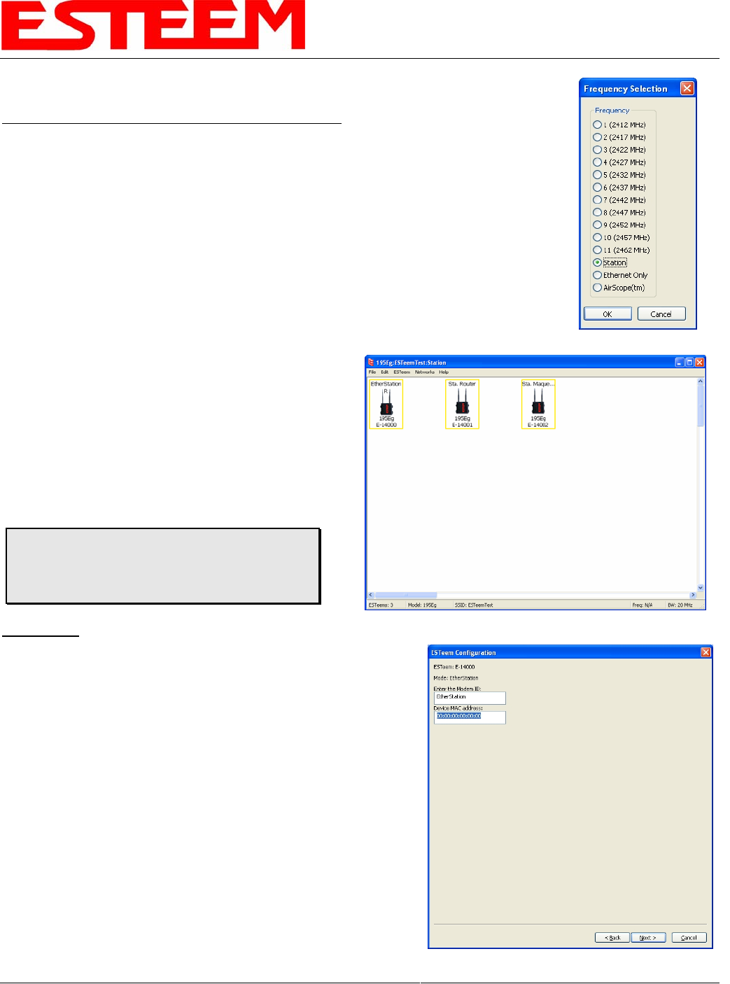
1. Starting a new network of ESTeem 195C/Ms in Mobile
Client mode is the same as any of the Bridge modes
except when you are asked for the frequency (channel)
of operation, select “Station” (Figure 23).
2. Add the three mobile client modems to the ENC Utility
configuration page as instructed above and set the
Modem ID to match the three modes of operation.
Your configuration will appear as in Figure 24.
EtherStation
3. By default, the ENC Utility sets all station mode ESTeem modems
to EtherStation mode. The only adjustment necessary to the
EtherStation modem in our example is to enter the connected
Ethernet device’s MAC address. The ESTeem 195C/M will
“clone” the Ethernet MAC address of the connected Ethernet
device. To configure the EtherStation modem, double-click on the
icon to bring up the ESTeem Summary window and press the Edit
button (Figure 20).
4. EtherStation mode should be selected in the Mode of Operation.
Press the Next button at the bottom of the window to continue.
Enter the connected Ethernet device’s MAC address in the
“Device MAC Address” box (Figure 25) and press the Next button
at the bottom of the window to continue.
5. Verify the encryption settings are correct for the 802.11 AP
network in which the EtherStation modem will be working and
press the Finish button to return to the configuration page.
Revised: 1 Oct 13 3-13 EST P/N AA107-195CM
Figure 23: Station
Figure 24: Station Mode Example Modems
Technical Tip: The ESTeem 195C/M’s in
Mobile Client modes do not have a specific
frequency of operation as can be seen in Figure
24.
Figure 25: MAC Address Entry
CHAPTER 3
EXAMPLE APPLICATIONS
Station Router and Station Masquerade
Revised: 1 Oct 13 3-14 EST P/N AA107-195CM
6. To configure the two other modems, double-click on their
icons to bring up the ESTeem Summary window and press
the Edit button (Figure 20).
7. Select Station Router for E-14001 and Station Masquerade
for E-14002 in the Mode of Operation (Figure 26). Press
the Next button at the bottom of the window to continue.
8. Continue through the configuration screens setting the
Station Router/Masquerade addressing to match the IP
address ranges for your network. For help with setting the
router addressing please refer to Router Address Examples
later in this chapter.
9. Verify the encryption settings are correct for the 802.11 AP
network in which the EtherStation modem will be working
and press the Finish button to return to the configuration
page.
10. Verify all ESTeem modems are connected to the same
switch as the computer running the ENC Utility and send
the configuration to all modems at the same time by
selecting ESTeem>ESTeem Configuration>Send Configuration to All ESTeems. Once the ENC Utility has downloaded
the configuration for both ESTeem 195C/Ms, the status box around the ESTeems will change from yellow to blue. This
indicates that the configuration was completed successfully and the ESTeem 195C/Ms are ready to be installed in the
application.
Figure 26: Mode of Operation Selection
CHAPTER 3
EXAMPLE APPLICATIONS
ROUTER ADDRESSING EXAMPLES
The following are examples of the IP addressing and subnets required for the ESTeem Router modes.
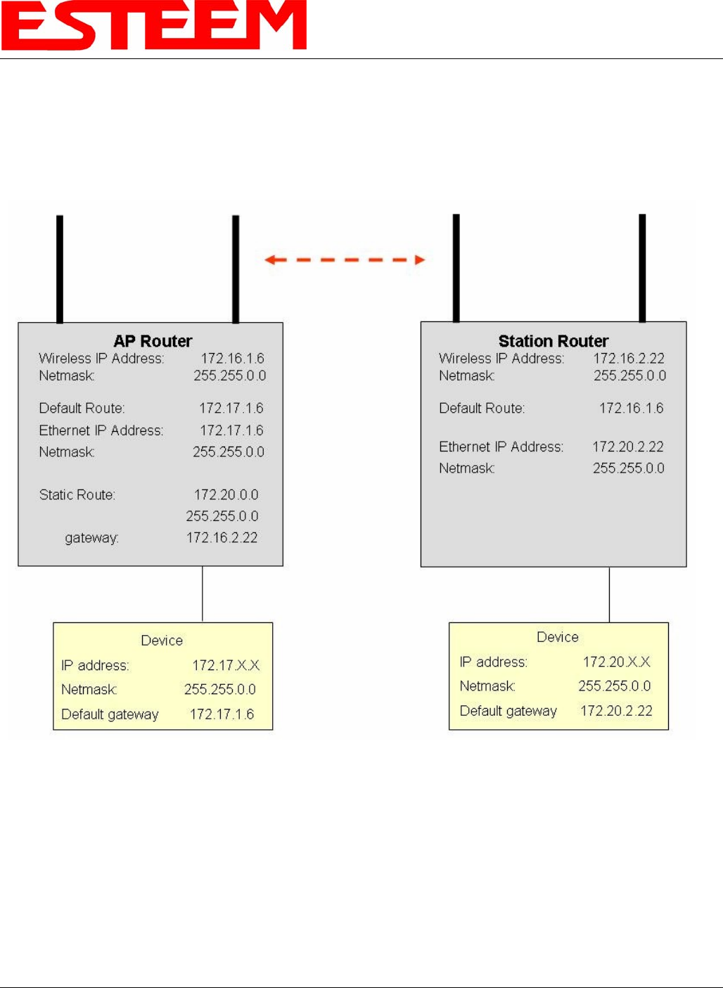
Point to Point Access Point Router to Station Router
Figure 27: AP Router Addressing Example
Revised: 1 Oct 13 3-15 EST P/N AA107-195CM
CHAPTER 3
EXAMPLE APPLICATIONS
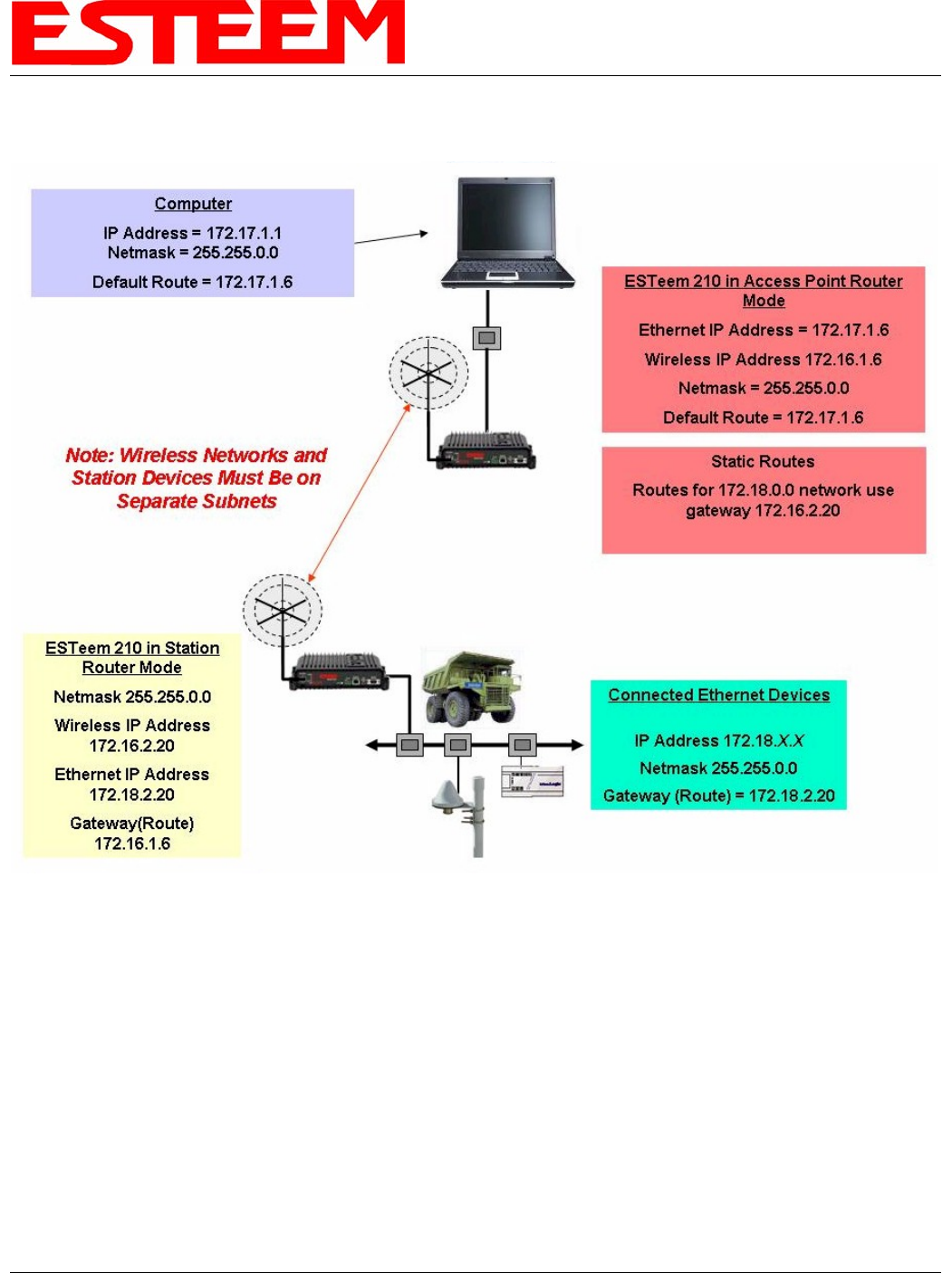
Stand-Alone Access Point Router and Single Station Router
Revised: 1 Oct 13 3-16 EST P/N AA107-195CM
Figure 28: Station Router Addressing Example
Static Routes
Routes for 172.18.0.0 network use
gateway 172.16.2.20
Note: Wireless Networks and
Station Devices Must Be on
Separate Subnets
ESTeem 195C/M in Access Point
Router Mode
Ethernet IP Address = 172.17.1.6
Wireless IP Address 172.16.1.6
Netmask = 255.255.0.0
Default Route = 172.17.1.6
ESTeem 195C/M in
Station Router Mode
Netmask 255.255.0.0
Wireless IP Address
172.16.2.20
Ethernet IP Address
172.18.2.20
Gateway(Route)
172.16.1.6
Computer
IP Address = 172.17.1.1
Netmask = 255.255.0.0
Default Route = 172.17.1.6
Connected Ethernet Devices
IP Address 172.18.X.X
Netmask 255.255.0.0
Gateway (Route) =
172.18.2.20
CHAPTER 3
EXAMPLE APPLICATIONS
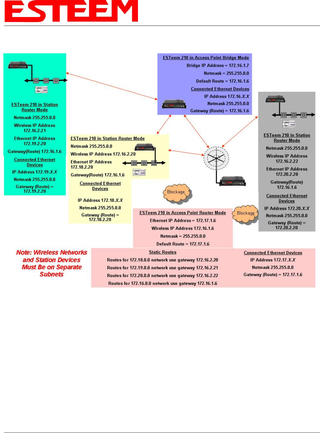
Stand-Alone Access Point Router with Multiple Station Routers
Figure 29: Complete Router Addressing Example
Revised: 1 Oct 13 3-17 EST P/N AA107-195CM
CHAPTER 4
UTILITIES & FEATURES
ESTeem Network Configuration Utility (ENC)
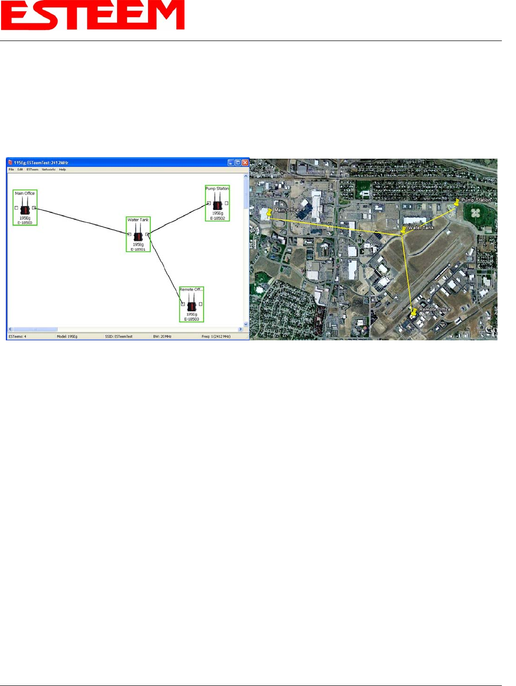
The ESTeem Network Configuration (ENC) Utility is a software program designed to greatly simplify the configuration of your
ESTeem Model 195C/M wireless Ethernet network. The ENC Utility will allow graphical, point-and-click configuration of your
network routing, then configure each ESTeem wireless modem for the network as designed (Figure 1). The ENC Utility will
eliminate the need to program or update each ESTeem wireless modem individually. The ENC Utility can send all wireless
modem configuration changes simultaneously to a new or existing network.
The ENC Utility will be used for all wireless network programming in this User’s Manual. For detailed instructions on the use of
the ESTeem Network Configuration (ENC) Utility please refer the ENC Utility User’s Guide available on the ESTeem Resource
CD or in the application itself.
Figure 1: ESTeem Network Configuration Utility
Revised: 1 Oct 13 4-1 EST P/N AA107-195CM

CHAPTER 4
UTILITIES & FEATURES
Revised: 1 Oct 13 4-2 EST P/N AA107-195CM
ESTEEM DISCOVERY UTILITY
The ESTeem Discovery Utility will allow you to
configure the IP address on the Model 195C/M to
match your network regardless of its current IP subnet.
This utility will also allow you to update the software in
the 195C/M and open the web configuration for that
wireless modem.
Installation
To install the Discovery Utility on your computer,
insert the Resource Disk in your CD drive.
Note: The ESTeem Resource Disk is a stand-alone
copy of the ESTeem Web site (Figure 2).
Navigation of the Resource Disk is as simple as
using your web browser. All technical documentation, User’s Manuals and the ESTeem Utility Program are available on
the disk.
Figure 2: ESTeem Resource Main Page
1. Place the ESTeem Utility CD in your CD-ROM drive. The CD will auto load the ESTeem main page
Note: If the page does not auto load, open your web browser and set your address line to D:\index.html (Where D: is the drive
letter for your CD-ROM drive).
2. From the Main Page select ESTeem Utilities and click on ESTeem Discovery Utility (Figure 3).
Figure 3: Discovery Utility Download
CHAPTER 4
UTILITIES & FEATURES
Note: This program is saved in a compressed file format.
3. Double click on the 195C/MDiscoverySetup<Current Version>.exe file listed in the window to install the program.
Figure 4: Discovery Program Main Page
4. Connect the Model 195C/M to your computer either directly to the Ethernet card or through a HUB/Switch using a CAT-5e
Ethernet cable. The Ethernet port on the 195C/M supports Auto-Negotiation, so either a patch cable or crossover cable will
work. Open the ESTeem Discovery Program and press the Discover Modems button. The Model 195C/M will be displayed
in the program by the Ethernet MAC address and Current IP Address (Figure 4).
Note: The SSID, Mode of Operation and Modem ID will be adjusted through the ENC Utility or the Web Configuration
Manager...
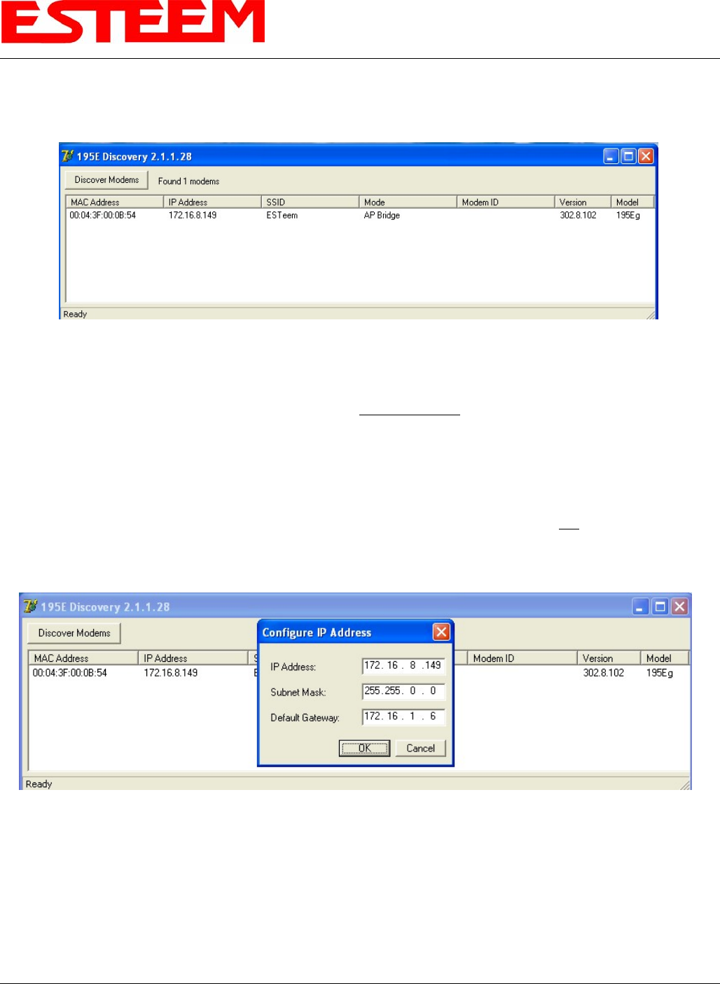
5. Double-click on the 195C/M you want to program and the Configure IP Address window will be displayed (Figure 5). Enter
an IP address and Subnet Mask for the 195C/M that matches your network subnet and press the OK button to save this to the
ESTeem. You will receive notification that the Configuration was Successful and the 195C/M will reboot.
Figure 5: Change IP Address Window
Revised: 1 Oct 13 4-3 EST P/N AA107-195CM
CHAPTER 4
UTILITIES & FEATURES
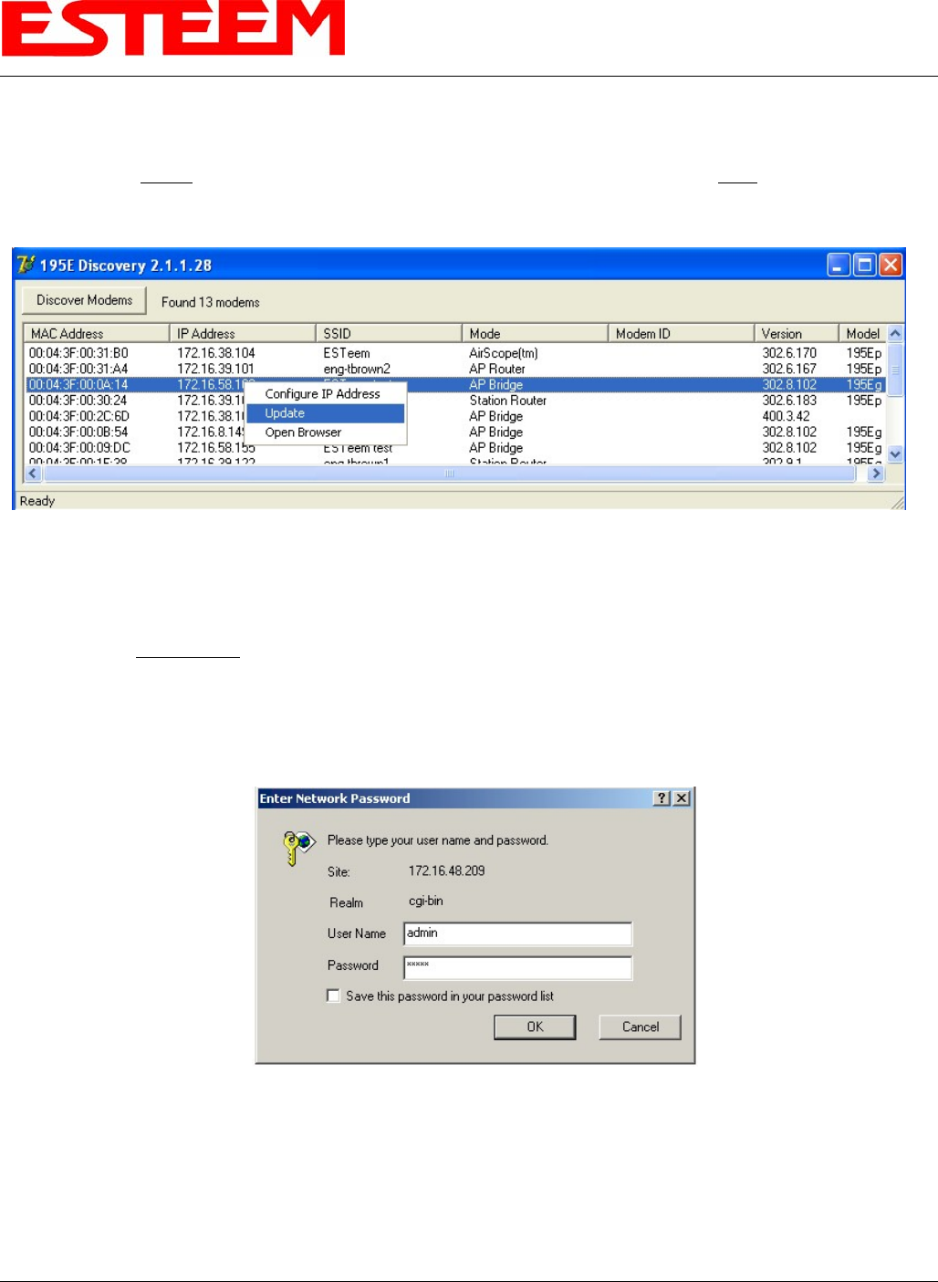
Firmware Updates
To update firmware on any ESTeem Model 195 that is shown on the Discovery program, “right-mouse” click on the 195’s MAC
address and select Update from the menu (Figure 6). Once you locate the update file, select the Open button and the 195 will
update, validate and then reboot with the updated operating system.
Figure 6: Discovery Features Menu
Opening Web Browser
To quickly open a web browser page to the IP address programmed in the 195 modem, “right-mouse” click on the 195’s MAC
address and select Open Browser from the menu (Figure 6). If your computer is configured for the same IP subnet at the ESTeem
195 wireless modem, you will be asked to sign in with the Username and Password (Figure 7). You can now begin programming
the Model 195 for your application.
Figure 7: ESTeem Web Page Log-on Screen
Revised: 1 Oct 13 4-4 EST P/N AA107-195CM
CHAPTER 4
UTILITIES & FEATURES
ETHERSTATION STATUS PROGRAM
When configured for EtherStation mode, the Web Configuration Manger is turned off. To gather information from the 195C/M
on Access Point, link status and received signal strength you will need to install the ESTeem 195C/M Status Utility. The
EtherStation Status Utility version 2.0.0.0 or greater provides a new feature that will automatically program the connected ESTeem
195C/M to match up with the computer running the software. This software requires the ESTeem 195C/M to have software
version 302.8.102 or greater installed for this feature to function.
This software program is found on the AA109 Resources Disk or available from the ESTeem web site. To install the utility,
please complete the following:
Installation
The ESTeem Discovery Utility will allow you to configure the IP address on the Model 195C/M to match your network. Install
the Discovery Utility on your computer by inserting the Resource Disk in your CD drive.
Note: The ESTeem Resource Disk is a stand-alone copy of the ESTeem Web site (Figure 1). Navigation of the Resource Disk is
as simple as using your web browser. All technical documentation, User’s Manuals and the ESTeem Utility Program are
available on the disk.
1. Place the ESTeem Utility CD in your CD-ROM drive. The CD will auto load the ESTeem main page.
Note: If the page does not auto load, open your web browser and set your address line to D:\index.html (Where D: is the drive
letter for your CD-ROM drive).
2. From the Main Page select ESTeem Utilities and click on EtherStation Status Utility
Note: This program is saved in a compressed file format. Microsoft Windows XP® will open the file directly, but other operating
systems will require a common compression program such as WinZip available for download at http://www.winzip.com
3. Double click on the 195C/MStatusSetup.exe file listed in the window to install the program.
4. Connect the Model 195C/M to your computer either directly to the Ethernet card or through a Switch using a CAT-5e
Ethernet cable. The Ethernet port on the 195C/M supports Auto-Negotiation so either a patch cable or crossover cable will
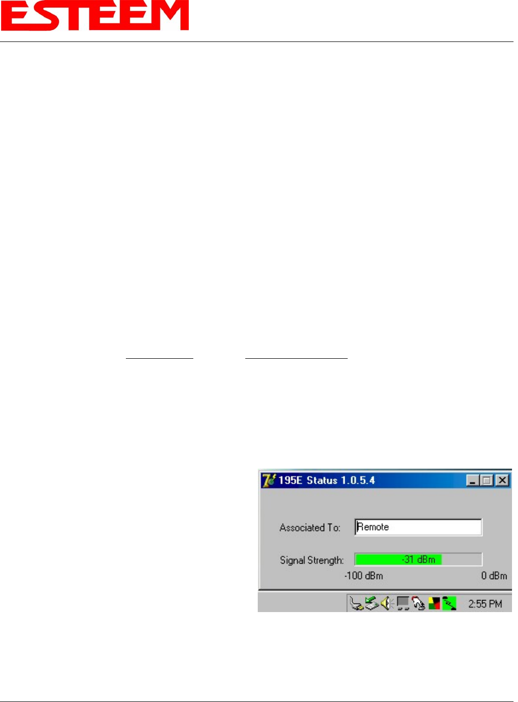
work. Open the ESTeem Status Program. Status icons will appear in your system tray (Figure 8). When the status menu is
opened from the system tray, the status window will be
displayed (Figure 8) to show the Access Point MAC
address and signal strength. The tray icon and Signal
Strength bar will display the colors from Green, Yellow
to Red on progressively poorer signal or will show Grey
if roaming.
Figure 8: EtherStation Status Program
Note: This Utility will only operate with an ESTeem Model
195C/M in EtherStation mode.
Revised: 1 Oct 13 4-5 EST P/N AA107-195CM
CHAPTER 4
UTILITIES & FEATURES
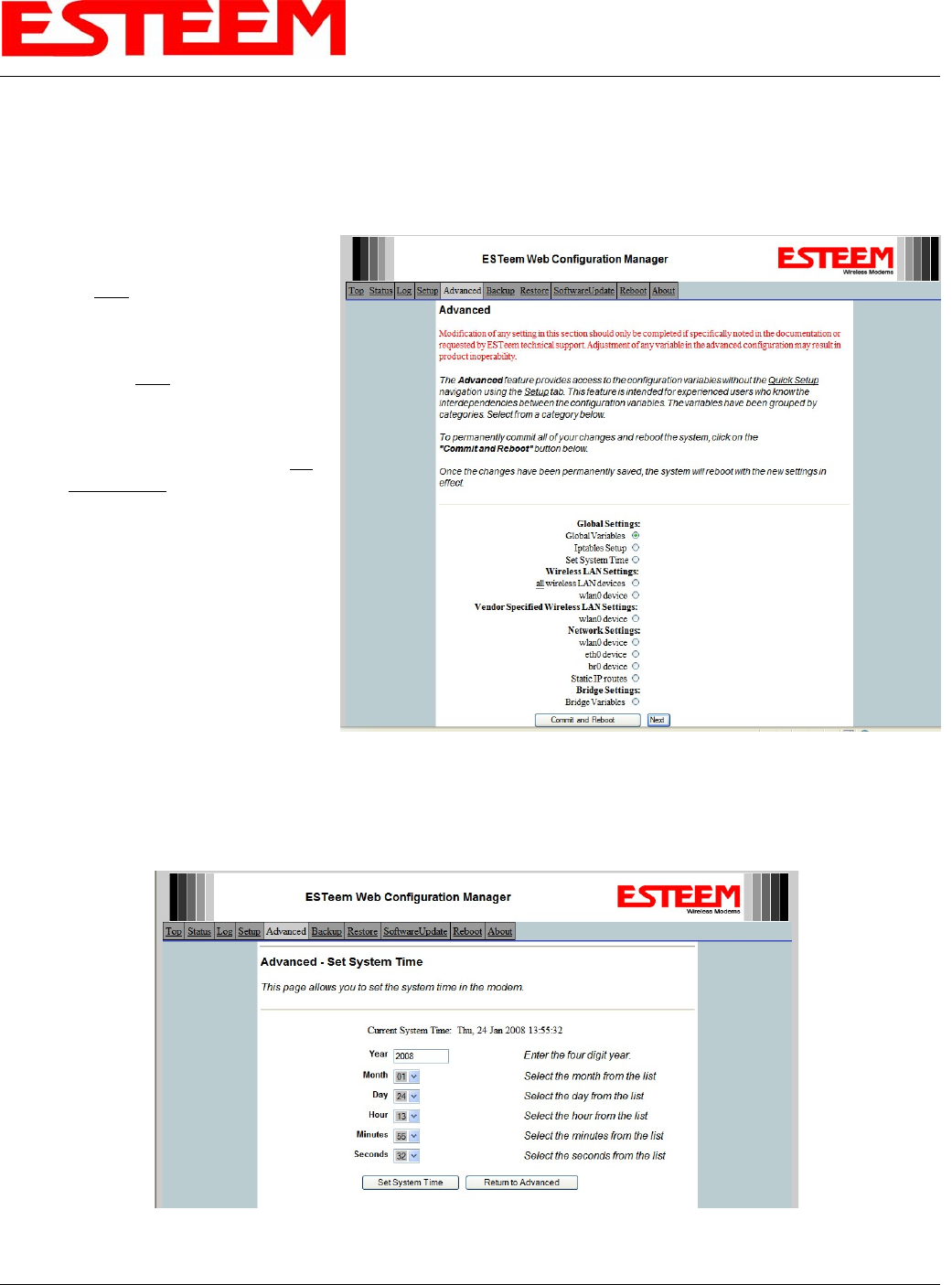
SETTING LOCAL TIME
The ESTeem Model 195C/M will be shipped from the factory with the internal real-time clock set to Pacific Time. To change the
clock settings to the local time for accurate log file entries:
1. Select Advanced from the top
Menu, then Wireless LAN
Settings>wlan0 device. Press
the Next button (Figure 9).
Revised: 1 Oct 13 4-6 EST P/N AA107-195CM
2. Select Global Settings>Set
System Time from the menu and
press the Next button to continue.
3. Select the correct date and time
from the drop-down menus
(Figure 10) and press the Set
System Time button to save the
time to the real time clock.
Figure 9: Advanced Features Screen
Figure 10: Advanced Features Screen
CHAPTER 4
UTILITIES & FEATURES
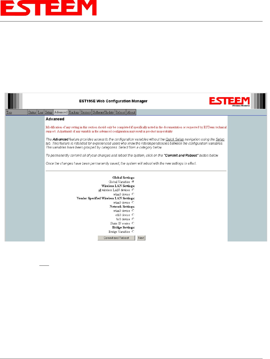
CONFIGURING TIME SERVER
Enabling NTP time synchronization services on the ESTeem 195C/M will allow usage of time services from upstream services to
keep the time on the system accurate.
To allow time synchronization, the Model 195C/M must be configured with the NTP Daemon enabled and the appropriate IP
address of the upstream network NTP server.
1. Select Advanced from the menu items and Global Variables (Figure 11).
Figure 11: Advanced Settings Menu
2. Press the Next button and Figure 11 will be displayed. At the bottom of the page are the NTP server configurations.
Revised: 1 Oct 13 4-7 EST P/N AA107-195CM
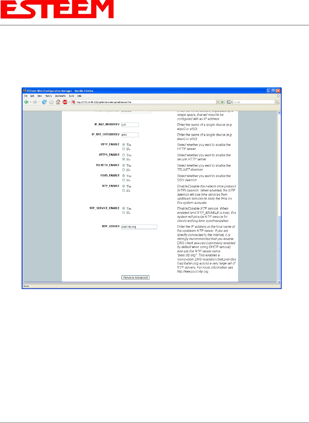
CHAPTER 4
UTILITIES & FEATURES
3. The NTP daemon is enabled by selecting YES for NTP ENABLE (Figure 12). When enabled, the NTP daemon will use
time services from upstream services to keep the time on this system accurate.
4. Next, the NTP SERVICE ENABLE should be configured to “YES,” if you want to allow the system to provide NTP
service for clients wishing time synchronization (Figure 12).
Figure 12: NTP Settings
5. The final step in configuring NTP services is to enter the IP address or the host name of the upstream NTP server.
Revised: 1 Oct 13 4-8 EST P/N AA107-195CM
CHAPTER 4
UTILITIES & FEATURES
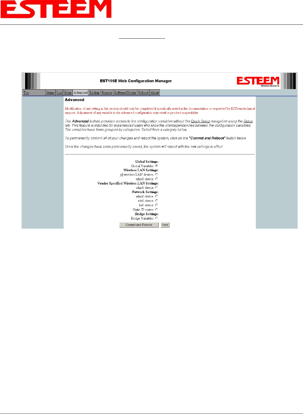
6. Once configuration is complete, press the Return to Advanced button.
7. To complete the configuration, select “Commit and Reboot.” The ESTeem 195C/M will now commit the configuration
changes and reboot. (Figure 13)
Figure 13: Advanced Settings Menu
Revised: 1 Oct 13 4-9 EST P/N AA107-195CM

CHAPTER 4
UTILITIES & FEATURES
Revised: 1 Oct 13 4-10 EST P/N AA107-195CM
Simple Network Management Protocol (SNMP)
The ESTeem 195C/M supports SNMP Version 1 (SNMPv1) and Version 2 (SNMPv2c) protocol. This protocol enables any
SNMP server to view the status of the wireless network while the system is in operation. The following are a list of the
Management Information Base (MIB) items that are supported in the ESTeem 195C/M and their MIB location:
MIB Name MIB Directory Location Notes
System Temperature EST-MIB::sysInternalTemp.0 in C * 1000
Uptime HOST-RESOURCES-
MIB::hrSystemUptime.0 System Update
ModemID EST-MIB::sysIdentifier.0 User-specified “nickname” for ESTeem
Serial Number EST-MIB::sysSerialNumber.0 ESTeem serial number
Model EST-MIB::sysModel.0 ESTeem model number
Firmware Version EST-MIB::sysFirmwareRevision.0 Firmware revision
System Mode EST-MIB::sysMode.0 AP_BRIDGE/STA_ETHERSTA, etc
Free Memory UCD-SNMP-MIB::memTotalFree.0 Total Free Memory
Idle CPU UCD-SNMP-MIB::ssCpuIdle.0 Percentage of CPU Idle
[[ per-interface ]]
IP Address IF-MIB::ifAddress
Port Speed IF-MIB::ifSpeed In bps
Port Status IF-MIB::ifOperStatus
Mac Address IF-MIB::ifPhysAddress
[[ per-wlandev entry ]] EST-MIB::wirelessDevicesNumber.0 Wireless Port Identification
Device Name EST-MIB::wirelessDeviceTable.1.wName.1 Name of device (wlan0 standard)
MAC Address
EST-
MIB::wirelessDeviceTable.1.wMacAddress.
1 MAC address of WLAN port
Mode EST-MIB::wirelessDeviceTable.1.wMode.1
Current Mode ap=access point, sta=station
mode and airscope
Frequency EST-MIB::wirelessDeviceTable.1.wFreq.1 Frequency in MHz
Bandwidth EST-
MIB::wirelessDeviceTable.1.wBandwidth.1 Bandwidth (5, 10, or 20 MHz if used)
SSID EST-MIB::wirelessDeviceTable.1.wSSID.1 Service Set Identification
BSSID EST-MIB::wirelessDeviceTable.1.wBSSID.1 Basic Service Set Identification
Operational Rates EST-
MIB::wirelessDeviceTable.1.wOpRates.1 List of RF Data Rates in Rate Set
Basic Rates EST-
MIB::wirelessDeviceTable.1.wBasRates.1 List of RF Basic Rates for status messages

CHAPTER 4
UTILITIES & FEATURES
[[ peer table entry ]]
All entries in the Peer Table will have a
device entry index, both ESTeem and
other wireless devices
EST-MIB::wirelessPeersNumber.0 Total number of peer entries in table
wlan device EST-MIB::wirelessPeerTable.1.pDevice.1 index into the wirelessDeviceTable (each
entry will have a unique number
Peer MAC Address EST-MIB::wirelessPeerTable.1.pMacAddr.1 MAC address of peer
isRepeater? EST-MIB::wirelessPeerTable.1.pRepeater.1 Is the peer an ESTeem repeater
isAP? EST-MIB::wirelessPeerTable.1.pAP.1 Is the peer an Access Point
isAssocSta? EST-MIB::wirelessPeerTable.1.pAssoc.1 Is the peer an Mobile Client
isAdhoc? EST-MIB::wirelessPeerTable.1.pAdhoc.1 Is the peer an AdHoc Station (802.11 only)
Frequency EST-MIB::wirelessPeerTable.1.pFreq.1 Frequency in MHz
current rate set EST-MIB::wirelessPeerTable.1.pCurRates.1 Current Operating Rates
last rx signal EST-MIB::wirelessPeerTable.1.pSignal.1 Receive Signal in –dBm
last rx noise EST-MIB::wirelessPeerTable.1.pNoise.1 Background Noise in –dBm
BSSID EST-MIB::wirelessPeerTable.1.pBssid.1 Basic Service Set ID (In Hex)
SSID EST-MIB::wirelessPeerTable.1.pSSID.1 SSID in Text
isValid? EST-MIB::wirelessPeerTable.1.pCurrent.1 True if peer info is for a “current” peer.
last rx EST-MIB::wirelessPeerTable.1.pLastRxl.1 seconds since last received packet from
peer
last tx EST-MIB::wirelessPeerTable.1.pLastTx.1 seconds since last transmitted packet to
peer
current tx rate EST-
MIB::wirelessPeerTable.1.pCurrentRate.1 current tx rate in bps.
Downloading MIB Tables
To download the MIB items listed above and import into your SNMP server, log into any ESTeem 195C/M and select the About
page (Figure 20). Press the Download MIB Files hyperlink on the page and save the files to your computer.
Figure 14: MIB Table Download
Revised: 1 Oct 13 4-11 EST P/N AA107-195CM

CHAPTER 6
SERIAL APPLICATIONS
USING THE USB PROGRAMMING PORT
Any terminal emulation program can be used for this configuration of the ESTeem 195C/M through the USB port. Most
Windows users will probably use either Hyper Terminal or the Terminal Emulation in the ESTeem Utility program.
Programming Using the USB Port
1.
2.
3.
4.
5.
6.
7.
8.
When configuring the Model 195C/M for the first time you can use the ESTeem Configuration Menu to setup the basic
operating parameters such as assigning the IP Address, IP Net Mask, and Gateway IP Address.
Connect the USB cable between the USB connector on the Model 195C/M to an open USB port on the computer.
Plug the Model AA174 power supply into a wall socket and connect an Ethernet patch cable from the Model 195C/M Ethernet
port to the J1 (Data&PWR) port on the power supply. The Power LED on the front of the ESTeem should be illuminated.
If your computer is configured properly, you will see the ESTeem Model 195C/M booting sequence on your Terminal
Emulation program. Once the ESTeem boot sequence is complete (approximately 45 seconds) you will receive this message:
“Please press Enter to active this console.”
If you don’t see this message press the Reset button on the front panel of the Model 195C/M and/or check the programming
of your RS-232 port.
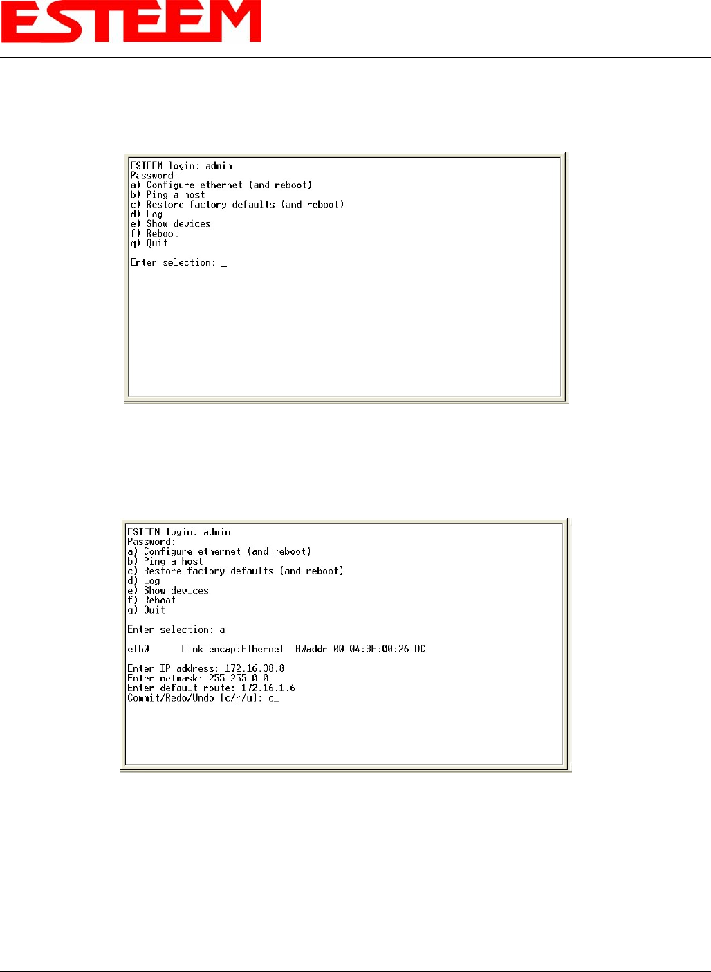
Press the Enter key and you will be at the Configuration Menu 195C/M login prompt. See Figure 1.
To enter the Model 195C/M Main Menu you will need to log into the system with a login name and password.
If this is not the first time configuration of the Model 195C/M, see your network systems administrator for the password.
At the 195C/M login prompt type admin for the login name and press the Enter key (<Enter>). The login name is defined at
the factory and is not changeable by the user. Note that all characters are lower case.
If this is the first time the Model 195C/M has been programmed or the Password was not changed from the factory default values,
the factory default password is also admin. Enter admin for the password and press the Enter key (<Enter>). The ESTeem
Configuration Welcome Screen (Figure 2) will now be displayed. Note that all characters are lower case.
Figure 1: RS-232 Port Log-in Screen
Revised: 1 Oct 13 6-1 EST P/N AA107-195CM
CHAPTER 6
SERIAL APPLICATIONS
9.
10.
To set the IP address in the ESTeem 195C/M, type the letter “A” and press the Enter key. Enter the value for the IP address,
Netmask and default route pressing the Enter key after each entry.
After the basic parameters have been entered into the Model 195C/M you will need to commit the changes to the Model
195C/M (Figure 3). Press the C key and then Enter. The changes will be saved to flash memory. You can use
programming features in the ESTeem Web Configuration Manager to configure the unit for your application.
Figure 2: RS-232 Welcome Screen
Figure 3: RS-232 Welcome Screen
Revised: 1 Oct 13 6-2 EST P/N AA107-195CM
CHAPTER 6
SERIAL APPLICATIONS
USING THE RS-232 DATA PORT
The ESTeem 195C/M has a serial data port that can provide RS-232 communication between two or more serial devices using the
wireless broadband link. The serial data is encapsulated and transferred as a standard Ethernet packet over an operating 195C/M
wireless Ethernet system. The configuration for a serial 195C/M network will be the same as an Ethernet or a serial (RS-232)
based communication network.
The serial interface option can be used to link two or more serial devices in a new or existing system. The serial data has very little
impact on the network bandwidth and will allow for both Ethernet and serial applications simultaneously. A possible application
would be installation of the 195C/M in an existing serial based network that was looking for future upgrade to an Ethernet based
system. Another would be using the high-bandwidth Ethernet connections to provide a link to remote video hardware while also
providing a serial link to the existing PLC in a SCADA type application.
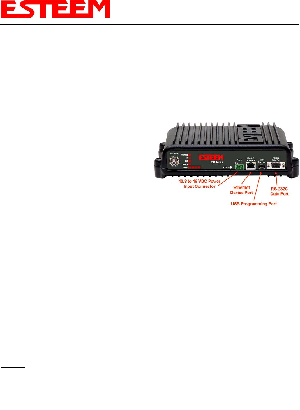
Figure 4: 195C/M Front Panel Overview
SERIAL CONNECTIONS
The 9-pin Sub-D serial data port is located on the face of the
195C/M (Figure 4). Using the ESTeem AA062 interface
cable, the 195C/M can be connected to a standard DTE-device
(PC) with a male 9-pin Sub-D connector. The complete cable
configuration is available in Appendix C – Interface Ports.
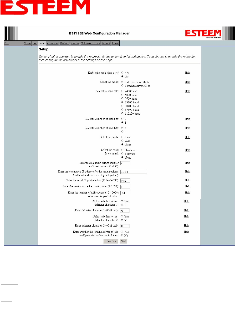
SERIAL CONFIGURATION
Configuration of the serial port is completed during the
standard setup of the 195C/M. After completion of the
Repeater Peer configuration screen, the Serial Port Setup
screen (Figure 5) will be displayed. Each section in the Serial
Port Setup screen is described in detail with the following:
Enable the RS-232 Data Port
Enabling the serial data port allows the modem to send RS-232 data over the broadband wireless connection established with the
ESTeem repeater peers. The modem can be configured in a point-to-point or point-to-multipoint system. Select Yes if you wish to
enable the serial data port.
Mode of Operation
There are two distinct modes of operation for the serial port in the 195C/M. The Redirector mode will provide two-way serial
communication between two or more serial devices, while the Terminal Server mode will allow serial communication to a specific
remote site by connecting through telnet or SSH. Select one of the following modes of operation:
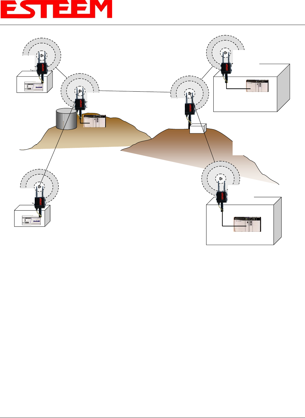
Full Redirector Mode - This mode allows bi-directional RS-232 data communication with other ESTeem Model 195C/M’s. The
RS-232 data transmission will appear transparent to the connected devices as if a serial cable is connected between the two ports.
This mode will also be used in a multi-point serial network were all serial devices will need bi-directional communication (Figure
6).
Terminal Server Mode - This mode of operation translates RS-232 serial data into a network-oriented terminal protocol, such as
telnet or SSH. This mode would be selected if an interactive RS-232 session at remote locations is desired over the wireless
Ethernet link.
Baud Rate
Select the data rate of the RS-232 connection to match your serial device.
Revised: 1 Oct 13 6-3 EST P/N AA107-195CM
CHAPTER 6
SERIAL APPLICATIONS
Figure 5: Serial Configuration Screen
Data Bits
Select the number of data bits on the RS-232 connection to match your serial device.
Stop Bits
Select the number of stop bits on the RS-232 connection to match your serial device.
Parity
Select the parity of the RS-232 connection to match your serial device.
Revised: 1 Oct 13 6-4 EST P/N AA107-195CM

CHAPTER 6
SERIAL APPLICATIONS
Revised: 1 Oct 13 6-5 EST P/N AA107-195CM
Flow Control
Select the type of data flow control used on the RS-232 connection. The ESTeem can support Hardware flow control (RTS/CTS
control lines) or Software Flow Control (XON/XOFF). Select None if no serial flow control is necessary.
Maximum Bridge Links for Multicast Packets
This value sets the maximum number of Ethernet bridge links that the multicast packets will be sent through when used in a multi-
point system. A multi-point serial network uses multicast packets (UDP) to send the data to more than one remote ESTeem. You
want to limit the number of network bridge links that these UDP packets will be passed through to make the network more
efficient.
If you are using multiple ESTeem repeater links to send the serial data to remote locations, the value for the maximum bridge link
needs to be increased to a number greater than the longest repeater chain. For example, if you are using four repeater (peer) links
to send the serial data between two or more sites the number will need to be five (5) or greater (Figure 4).
Destination IP Address
The ESTeem configured for the correct destination IP and port number will send and receive the serial data from another modem.
Set the destination IP address for the ESTeem where the serial data will be sent. If sending to more than one ESTeem (Multipoint)
set to a multicast address (i.e 224.0.0.1).
Note: If you are using the ESTeem 195C/M in a multipoint application (multicast), you must have default Gateway configured
in the ESTeem set to the IP address of the Root Bridge modem.
Serial IP Port Number
The ESTeem configured for the correct destination IP and port number will send and receive the serial data from another modem.
Set the IP port numbers to match where the serial data will be sent. The serial data will not be sent if both the IP address and port
number is not correct.
Maximum Packet Size
This number represents the maximum size of the serial data packet in bytes. If the number of bytes of data in the serial port buffer
exceeds the maximum packet size before the timer or delimiter character is reached, the ESTeem will send forward the serial
packet. For example, if the maximum packet size is set to a value of 100, when the serial port receives 100 bytes the data will be
sent through the wireless connection.
Number of Milliseconds for Packetization
This number represents the time the ESTeem will hold data in the serial data buffer before sending to the remote ESTeem. This
feature is generally used if the serial data does not have a consistent packet length or delimiter character. For example, if the
number of milliseconds is set to a value of 10 the ESTeem will monitor the incoming serial data stream and any break in characters
longer than 10 milliseconds will cause the data will be sent through the wireless connection.
Delimiter Characters
Enabling and specifying a delimiter character will transmit the data in the serial buffer when the delimiter character is recognized
in the serial data stream. There are two unique delimiter characters that can be configured and enabled independently.
Terminal Server Control Lines
Enabling this feature will allow the ESTeem in the Terminal Server mode to read and generate modem control lines to the
connected device.
CHAPTER 6
SERIAL APPLICATIONS
Remote Site & Repeater Repeater
Remote Site
Access Point
Bridge with
Repeater Mode
Remote Site
Access Point
Bridge with
Repeater
Mode
Access Point
Bridge with
Repeater
Mode
Access Point
Bridge with
Repeater Mode
Access Point
Bridge with
Repeater
Mode
Line-of-Sight Path
NOTE:
Repeater may be stand-
alone or attached to a
network or device.
Line-of-Sight Path
Line-of-Sight Path
Line-of-Sight Path
Line-of-Sight Path
Access Point
Bridge with
Repeater
Mode
Note:
Antenna’s shown are for
illustration purposes. There
are many antenna options
available depending on your
application.
Master PLC
RS-232 Data
Remote PLC
RS-232 Data
RS-232 Data
RS-232 Data
RS-232 Data
Figure 6: Serial Full Redirector Example
Revised: 1 Oct 13 6-6 EST P/N AA107-195CM
CHAPTER 7
REPEATING FEATURES
Revised: 1 Oct 13 7-1 EST P/N AA107-195CM
When programmed in any of the three Access Point (AP) Repeater Modes, the Model 195C/M will create a wireless network with
other Model 195C/M units in radio range that are programmed in the AP Repeater Peer table during setup. This feature adds the
increased functionality of repeaters to the typical Ethernet Bridge configuration.
ESTEEM MESH NETWORK
One of the most powerful features of the AP Repeater Mode is the ability to input multiple communication routes and designate
the priority for each of these routes to create a wireless Mesh network. The ESTeem Model 195C/M will automatically change
communication routes in the network if a route has failed. The new route will be based upon the priority level set during
configuration. This wireless Meshing technology allows the RF network to “self-heal” if any of the communication paths fail.
The routing priority is manually set during the configuration of the 195C/M. A manual path configuration is far superior to
standard “self-discovery” networks, because you have direct control over the best RF paths and can easily identify any failed
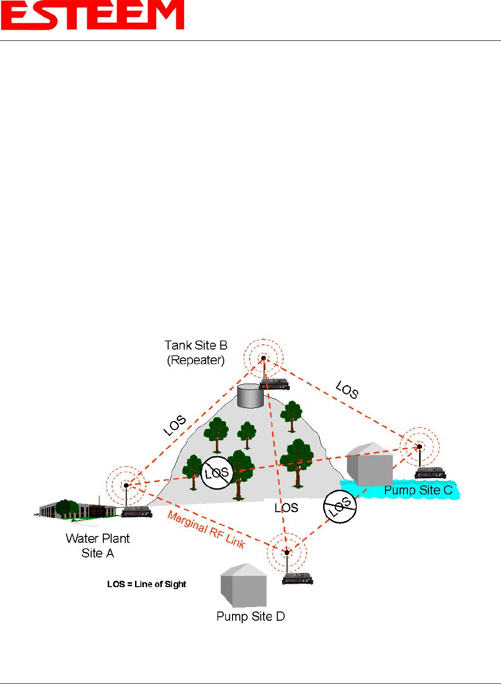
routes for easy troubleshooting. For example, Figure 1 shows a typical wireless Ethernet system used in the Water/Waste Water
Industry. The problem with a standard “self-discovery” Mesh network is the selection of routes. Notice that the communication
between the Water Plant (Site A) and Pump Site D has a marginal link, but it is the most direct route between the Ethernet devices.
This scenario poses the question, which path will the network select? The ESTeem Mesh Network takes out the guessing games
by allowing the user to select and prioritize all communication routes in the system. In our example we would want the primary
link to go through Tank B (Repeater) and use the direct link only if this primary link fails. The following sections will show how
this completed.
Figure 1: Small Mesh Network Diagram
CHAPTER 7
REPEATING FEATURES
Revised: 1 Oct 13 7-2 EST P/N AA107-195CM
Configuration
The configuration of the repeater paths is completed during setup of the Access Point modes. All three Access Point modes
support repeating and Meshing features. The Mesh network configuration using the ESTeem Network Configuration (ENC)
Utility is shown in detail in Chapter 3 of this User’s Manual.
Figure 2: Repeater Configuration Example
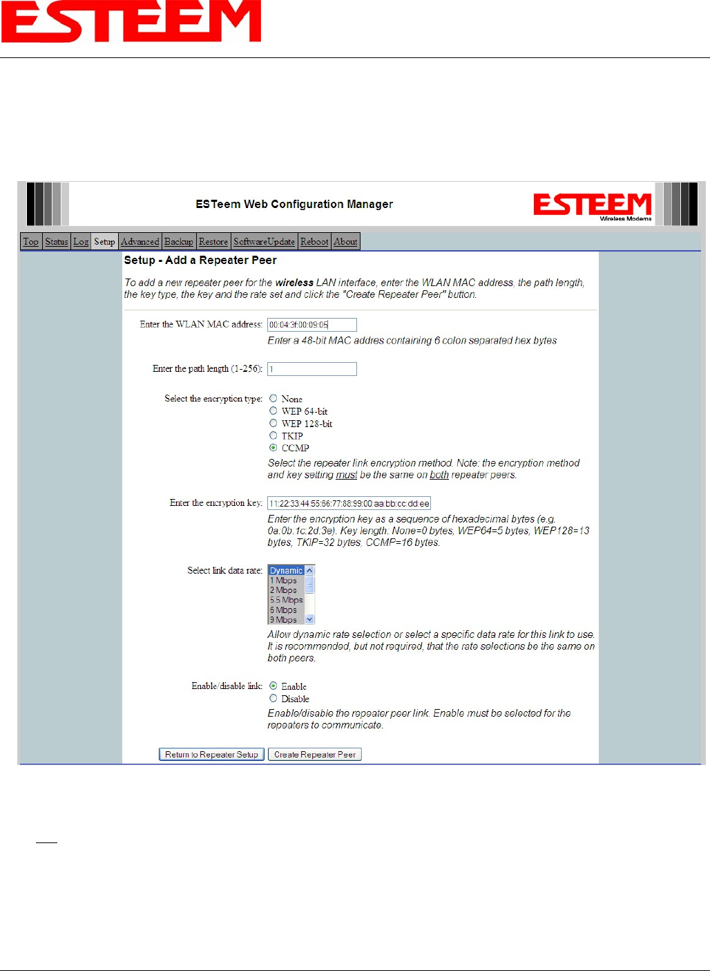
You can also configure the Mesh networking directly through the web configuration setup (Chapter 5). Figure 2 shows an
example repeater peer table from the setup menus. For an ESTeem 195C/M to communicate with another ESTeem 195C/M,
select Yes must at Enable Repeater Capability. Next, the Wireless LAN (WLAN) MAC address of each Model 195C/M that will
have direct communications must be added to the Repeater Peer List. Finally, enabling the link allows the corresponding 195C/M
to be included in the communication routing. Mobile clients do not require input in the repeater peer table. If multiple Mesh routes
are configured, you will also need to set the values for Priority and Path Costs (explained in Spanning Tree below). For multiple
examples of repeater configurations, please refer to Chapter 3 of this user’s manual.
CHAPTER 7
REPEATING FEATURES
Revised: 1 Oct 13 7-3 EST P/N AA107-195CM
RAPID SPANNING TREE PROTOCOL (RSTP)
The ESTeem Model 195C/M uses Rapid Spanning Tree Protocol (RSTP - IEEE 802.1d) to determine the radio routing structure of
the wireless network. This RSTP functions the same as standard Spanning Tree Protocol (STP) listed below, but the network
recovery is three times faster. If the 195C/M is used in a network that has any older STP only modems, the entire network will be
STP.
SPANNING TREE PROTOCOL (STP)
The ESTeem Model 195C/M uses standard Ethernet Spanning Tree Protocol (STP) or Rapid Spanning Tree Protocol (RSTP) to
determine the radio routing structure of the wireless network. The primary purpose of STP/RSTP is to make sure that “network
loops” are not created. A network loop is having two communication paths to the same destination where the remote device would
receive the same data multiple times. If there were no way to control the data flow, this data would be constantly passed around
this loop causing a “packet storm” that would shut down the entire network. The Spanning Tree Protocol will block all these
redundant links.
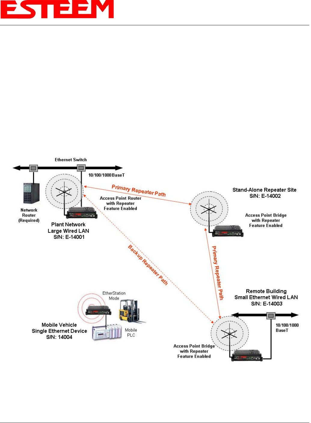
Figure 3: Programming Example #1 Diagram
The STP operation begins by determining which Ethernet device on the network will be the Root Bridge. All Ethernet networks
have a Root Bridge that is selected by the lowest MAC address. All path costs are evaluated against this Root Bridge device to