Electronic Systems Technology ESTEEM195C 450-470MHz Narrow-band UHF modem User Manual ESTEEM USERS MANUAL
Electronic Systems Technology 450-470MHz Narrow-band UHF modem ESTEEM USERS MANUAL
Contents
- 1. User Manual Part 1
- 2. User Manual Part 2
User Manual Part 2

CHAPTER 7
REPEATING FEATURES
Revised: 1 Oct 13 7-4 EST P/N AA107-195CM
determine routing and which paths will be blocked. On a wired Ethernet network, the location of the Root Bridge is not really
important, but in a wireless network selection of the Root Bridge is critical to the wireless network routing. Let’s use one of the
Example network diagrams from Chapter 3 to continue the discussion (Figure 4).
STP Phases
The following sections describe the process of the STP in the ESTeem Model 195C/M as how it would happen in the above
example.
Learning Phase - Once properly configured, each Model 195C/M will begin to search out the other Model 195C/M units in radio
range that are programmed in the AP Repeater Peer table. All Model 195C/M’s will calculate their routes to every Model 195C/M
in the network based upon the lowest “path length” to the Root Bridge. Path length is the total number of wireless links (repeater
peer links) to transmit a packet through the wireless network to the Root Bridge. Note: The Root Bridge in a network should be
the Model 195C/M where the majority of the data flow is processed. In every wireless network of two or more radios, the Root
Bridge should be user defined. If not defined, the ESTeem 195C/M with the lowest MAC address will be designated as the Root
Bridge.
In Figure 4, the Plant network (Example 1) is the most logical location for the Root Bridge based upon the amount of data flow.
Setting this site as the root bridge is discussed below in Root Bridge.
Blocking and Forwarding Phase – To ensure you do not have a network loop situation due to redundant paths in your wireless
network, the Model 195C/M will recognize and disable (block) one or more redundant links and provide back up links should the
primary link fail. This establishes a wireless mesh network with a series of forwarding links, based upon the shortest path length to
the Root Bridge.
For example, looking at Figure 4, the Remote Building has two routes to the Root Bridge (Plant Network – Example #1); directly
to the site and through the repeater. The direct link between the two sites is the shortest route (lowest Path Length) and will be
selected as the primary route unless overridden by manually changing the Path Length in the configuration.
Path Length
If more than one communication path to the Root Bridge is found, the 195C/M must determine which route to take based upon the
lowest Path Length. The default path length to all links in the 195C/M network is 1. If the Path Lengths are equal then the lowest
MAC address will determine the priority route. In the ESTeem Mesh Network we want to directly control all data flow so do not
want the routes to be automatically determined.
Looking again at our Example in Figure 4, if we made no changes to the default path length of 1 (note values in Figure 3) the
lowest path cost would be direct from the Remote Building to the Root Bridge (Plant Network).
Link Description Total Path Length
Direct from Remote Building 1
Remote Build to Root Bridge Through
Repeater 2
(Length 1 to repeater + Length 1 to Master = 2)
To configure the 195C/M to select the repeater as the primary radio path, set the path length value for the direct link greater than 2
(such as a value of 3) to make this the primary radio path. The lowest path length will identify the highest priority. The Model
195C/M will use this routing, but also switch to direct communication if the repeater were to disappear.
Root Bridge
In any Access Point Repeater network consisting of more than two sites, one Model 195C/M should be designated as the Root
Bridge. Only one Model 195C/M can be designated as the Root Bridge in a given network and should be located where the
majority of the Ethernet data flow is processed. This site may be the Master location in a SCADA network or could be configured
CHAPTER 7
REPEATING FEATURES
Revised: 1 Oct 13 7-5 EST P/N AA107-195CM
at a repeater site. Selection is important because all Model 195C/M’s NOT configured as the Root Bridge will choose routing
based upon the Path Length to the Root Bridge. If you have any question as to which site in your AP Repeater application should
be the Root Bridge, contact ESTeem Customer Support at 509-735-9092 or e-mail your application to support@esteem.com.
The Root Bridge will be selected in one of two ways: the Root Bridge can be manually set (recommended) during the
configuration of the Repeater Peer table (Figure 3) or the Root Bridge designation will default to the lowest MAC address of all
the Model 195C/M’s in the network. The manual Root Bridge configuration is located in the “Advanced Settings” section.
Redundant Backup
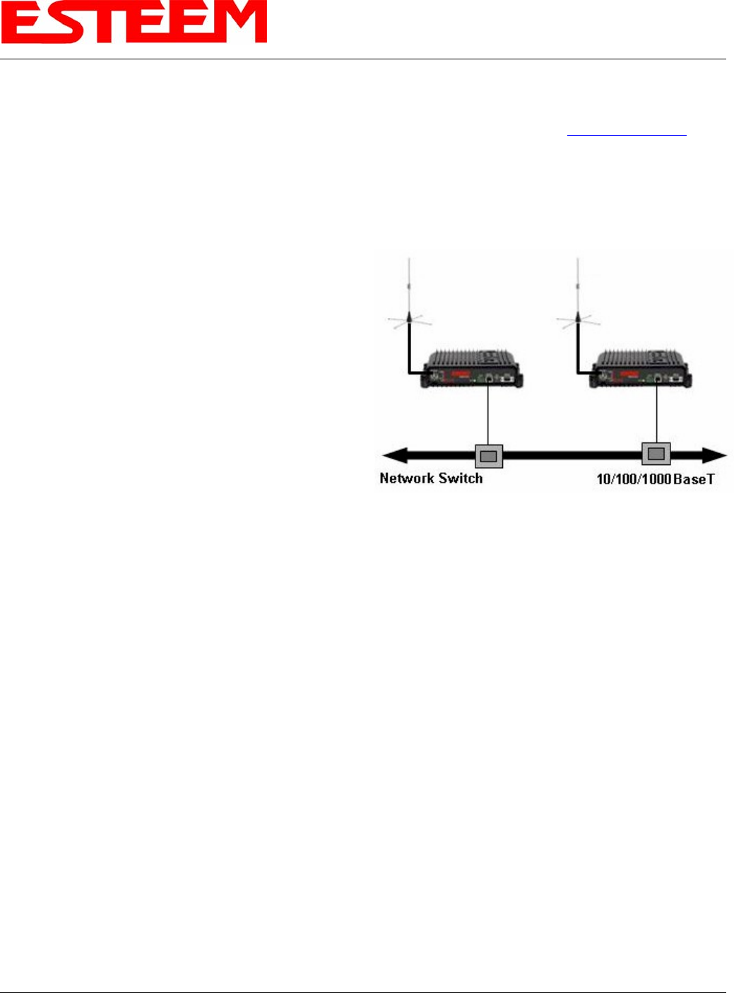
Figure 4: Redundant Backup Diagram
The ESTeem Model 195C/M configured in Access Point
Repeater mode will automatically function as a redundant
backup if two Model 195C/M’s are installed at the same location
(Figure 4). If two Model 195C/M’s are connected to the same
switch, one of the Model 195C/M’s will be Blocked when the
Spanning Tree Protocol is completed. The network will
continue to use this route until any problem with the original
Model 195C/M is detected and the second Model 195C/M will
begin operation at that site.
Redundant Master Configuration
The configuration in Figure 4 will also provide a redundant
backup for the Master Site (Root Bridge). Configure both Model
195C/M’s as Root Bridges (see above) giving the primary Root
Bridge a value of 1 and the secondary Root Bridge a value of 2.
CHAPTER 8
ANTENNA SETUPS
Revised: 1 Oct 13 8-1 EST P/N AA107-195CM
ESTeem offers different types of antennas ranging from ¼ wave to 5/8 wave in physical size. The user choice is dependent on the
application.
Communications in the VHF and UHF bands are normally over "Line of Sight (LOS)". Looking from the antenna of one wireless
modem you must be able to see the antenna of the wireless modem you wish to communicate with. If a large object obstructs the
line of sight view it is unlikely that satisfactory communications will result. This means you must relocate the antennas or use the
REPEATER FEATURE and a second modem to go over or around the object.
The Model 195C/MC products are allowed by the FCC to use high gain directional antennas.
It is noted that a ¼ wave antenna that does not have ground plane radials requires a ground plane to operate at maximum
efficiency. This can simply be a conducting surface under the antenna that is a ¼ wavelength in diameter. For the Model 195C
(450-470 MHz) this is approximately 6.5 inches. A conducting surface can be anything from the rooftop of an automobile to a file
cabinet.
COAXIAL CABLES
To minimize signal loss, the overall length of the coaxial cable should be as short as possible. To avoid corrosion select coaxial
cable manufacturers with tinned copper braid, where possible. Listed below are representative cable losses in db/100ft at the VHF
and UHF frequencies:
Frequency
(MHz)
RG-58u
LMR 195
RG-8
(solid)
LMR600
1/2" Heliax
150-174 -5.2 -4.4 -1.7 -0.964 -0.88
402-420 -8.4 -7.8 -2.9 -1.72 -1.36
450-470 -9 -7.8 -3 -1.72 -1.45
In a severe noise environment it may be desirable to use a double shield type of coax cable such as RG-214/U.
Note: Pre-made coax cables can be purchased from the factory. A -3 dB loss means you have lost 1/2 of your signal. A +3 dB
gain means you have doubled (x2) your signal.
Keep the antenna feedline as short as possible to minimize losses.
Extreme care must be taken when attaching coax connectors to the antenna feedlines. If there is any error in making
this connection the output of the transmitter will be greatly reduced.

CHAPTER 8
ANTENNA SETUPS
WEATHER PROOFING COAX CONNECTIONS
1. Lightly coat the threads of the connectors with silicone lubricant prior to assembly (See Note 1) and hand tighten.
Make sure to use the silicon sparingly so when assembled, any excess does not get on center conductor. Care
should be taken not to get any lubricant on the center conductor.
2. Wrap the connector assembly with a non-adhesive silicone tape, EST part number AA243, for weather proofing
(See Note 2 and instructions below).
a) Clean surface to be wrapped. Cut off length to be used.
b) Peel back a short length of protective film. Keep tape clean and dry.
c) Begin with one complete overlap of tape onto itself.
d) STRETCH CoaxWrap while continuing to wrap object with “half-laps”, removing clear film as you go (Figure
1). For greater pressure resistance, use 2 or more tightly wrapped layers.
e) End of tape at final wrap should be completely positioned onto itself.
Figure 1: Installation Example
Note: CoaxWrap’s bond begins to cure immediately upon contact with itself.
Repositioning or removal is not recommended after 2 minutes of wrapping.
3. Apply an electrical coating (sealing agent), over the vapor barrier patch for added
protection (See Note 3).
NOTES:
1. Dow Corning RTV-3140 or equivalent.
2. CoaxWrap, CW10B or equivalent.
3. SCOTCHKOTE, 3-M Company, or equivalent.
Revised: 1 Oct 13 8-2 EST P/N AA107-195CM
CHAPTER 8
ANTENNA SETUPS
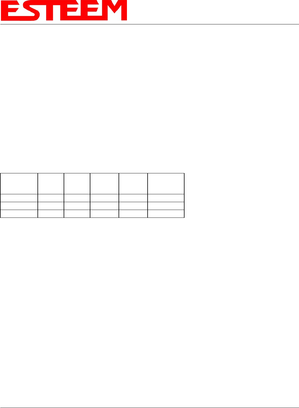
Model 210C Outdoor
Fixed Base Hardware Diagram
NOTES
1. Use coax cable runs as short as
practical to minimize cable losses.
2. Vapor wrap all external antenna coax
connections with Silicone tape (EST
Part No. AA243).
3. Contact ESTeem for recommendations
regarding antenna mounting hardware
and installation tips.
4. Ground antenna structure, base and
lightning arrestor.
Directional
Antenna
Directional
Antenna
Omni-Directional
Antenna
ANTENNA RECOMMENDATIONS
1. Omni-Directional (EST P/N AA20C.1
or FG4507 & FG4607).
2. Directional (EST P/N AA202C.1).
Antenna Feedline Recommendations
EST Antenna Part No.
Feedline
Type 20C.1 202C.1 FG4507/FG4607
< 50 ft. Length RG-8 AA237 AA237 AA237
> 50 ft. Length Helaix AA236 AA236 AA236
N Male
Connector N Male
Connector
TNC Male
Connector
RG-8 Coax
EST Part No. AA234
Lightning Arrestor
(EST Part No. AA161)
Earth Ground
Ethernet and RS-232C
Interfaces to User’s Devices
USB Programming Port
Power Interface
Cable/Connector
12 VDC Power Supply
(EST Part No. AA178)
12 VDC Power Supply
(EST Part No. AA178)
Revised: 1 Oct 13 8-3 EST P/N AA107-195CM

APPENDIX A
FCC INFORMATION
Revised: 4 Nov 13 APX A-1 EST P/N AA107-195CM
INFORMATION TO USERS
WARNING: This equipment has been tested and found to comply with the limits for a Class A digital device, pursuant to Part
15 of the FCC Rules. These limits are designed to provide reasonable protection against harmful interference
when the equipment is operated in a commercial environment. This equipment generated, uses, and can radiate
radio frequency energy and, if not installed and used in accordance with the instruction manual, may cause
harmful interference to radio communications. Operation of this equipment in a residential area is likely to cause
harmful interference in which case the user will be required to correct the interference at their expense.
To insure compliance to FCC non-interference regulations, peripherals attached to this modem require shielded
I/O cables.
If this equipment does cause interference to radio or television, which can be determined by turning the
equipment off and on, the user is encouraged to try to correct the interference by one or more of the following
measures:
1. Re-orient the radio/TV-receiving antenna.
2. Re-orient the modem antenna.
3. Relocate the modem with respect to the radio/TV-receiving antenna.
4. Plug the power supply for the modem into a different outlet so that the modem and radio/TV receiver are on different
branch circuits.
5. Verify that the modem chassis is connected to an earth ground.
6. Attach a split bead (FAIR-RITE PN 2643164251) to the RS-232 cable.
If necessary, the user should consult the dealer or an experienced radio/TV technician for additional suggestions. The user may
find the following booklet prepared by the FCC helpful.
"How to Identify and Resolve Radio-TV Interference Problems"
This booklet is available from the U.S. Government Printing Office, Washington, D.C. 20402 - Stock No. 004-000-00245-4.
Application forms for the license are available from the nearest office of the FCC.
Electronic Systems Technology maintains a list of consultants that provide professional services at a reasonable cost to assists
the users in licensing.
RF EXPOSURE WARNING: A minimum separation must be maintained between the user and nearby antenna at the
following distances:
Antenna AA19C: 1 meter (40 inches)
Antenna AA20C.1: 1.25 meters (50 inches)
Antenna AA202C: 2.5 meters (100 inches)
Antenna AA19M: 1 meter (40 inches)
Antenna AA20M: 2 meters (80 inches)
Antenna AA202M: 2 meters (80 inches)

APPENDIX A
FCC INFORMATION
Revised: 4 Nov 13 APX A-2 EST P/N AA107-195CM
Type Acceptance and RF Emissions Information
Model 195C
12.5 KHz Channel Spacing, 9,600 bps
FCC Type Acceptance No: ENPESTEEM195C
12.5 KHz Channel Emissions Designator: 10K8F1D
6.25 KHz Channel Emissions Designator: 5K4F1D
Industry Canada Type Acceptance: 2163A-192195C
12.5 KHz Channel Emissions Designator: 10K8F1DDN
6.25 KHz Channel Emissions Designator: 5K4F1DDN
Model 195M
12.5 KHz Channel Spacing, 9,600 bps
FCC Type Acceptance No: ENPESTEEM195M
12.5 KHz Channel Emissions Designator: 10K8F1D
6.25 KHz Channel Emissions Designator: 5K4F1D
Industry Canada Type Acceptance: 2163A-192195M
12.5 KHz Channel Emissions Designator: 10K8F1DDN
6.25 KHz Channel Emissions Designator: 5K4F1DDN

APPENDIX A
FCC INFORMATION
Revised: 4 Nov 13 APX A-3 EST P/N AA107-195CM
FEDERAL COMMUNICATIONS COMMISSION FIELD OFFICES
ALASKA
1011 E. Tudor Rd.
Rm 240 Box 2955
Anchorage, AK 99510
CALIFORNIA
Interstate Office Park
4542 Ruffner St., Room 370
San Diego, CA 92111-2216
Los Angeles Office (LA)
Ceritos Corporate Tower
18000 Studebaker Rd., Room 660
Cerritos, CA 90701-3684
San Francisco Office (SF)
5653 Stoneridge Drive, Suite 105
Pleasanton, CA 94588-8543
COLORADO
Denver Office (DV)
215 S. Wadsworth Blvd., Suite 303
Lakewood, CO 80226-1544
FLORIDA
919 Federal Bldg
51 SE First Ave.
Miami, FL 33130
Tampa Office (TP)
2203 N. Lois Ave., Room 1215
Tampa, FL 33607-2356
GEORGIA
Atlanta Office (AT)
3575 Koger Blvd., Suite 320
Duluth, GA 30096-4958
HAWAII
7304 Prince Kuhi
Federal Building
Honolulu, HI
ILLINOIS
Chicago Office (CG)
Park Ridge Office Ctr., Room 306
1550 Northwest Highway
Park Ridge, IL 60068-1460
LOUISIANA
New Orleans Office (OR)
2424 Edenborn Ave. Suite 460
Metarie, LA 70001
MARYLAND
1017 Geo. Fallon
Building 31
Hopkins Plaza
Baltimore, MD
MASSACHUSETTS
Boston Office (BS)
1 Batterymarch Park
Quincy, MA 02169-7495
MICHIGAN
Detroit Office (DT)
24897 Hathaway Street
Farmington Hills, MI 48335-1552
MINNESOTA
691 Federal Building
316 N Robert St.
St. Paul, MN
MISSOURI
Kansas City Office (KC)
520 NE Colbern Road
Second Floor
Lee’s Summit, MO 64086
NEW YORK
1307 Federal Building
111 W. Huron
Buffalo, NY 14202
NEW YORK
New York Office (NY)
201 Varick Street, Suite 1151
New York, NY 10014-4870
OREGON
1782 Federal Building
1220 SW 3rd Avenue
Portland, OR 97204
PENNSYLVANIA
Philadelphia Office (PA)
One Oxford Valley Office Bld.
Room 404
2300 E. Lincoln Hwy
Langhorne, PA 19047-1859
PUERTO RICO
747 Federal Building
Carlo Chardon Ave.
Hato Rey, PR 00918
TEXAS
Dallas Office (DL)
9330 LBJ Freeway, Room 1170
Dallas, TX 75243-3429
5636 Federal Building
515 Rusk Avenue
Houston, TX 77002
WASHINGTON DC
Columbia Office (CF)
9300 East Hampton Drive
Capitol Heights, MD 20743
WASHINGTON
Seattle Office (ST)
11410 NE 122nd Way
Room 312
Kirkland, WA 98034-6927
APPENDIX B
INTERFACE PORTS
Revised: 26 Sep 2013 APX B-1 EST P/N AA107-195CM
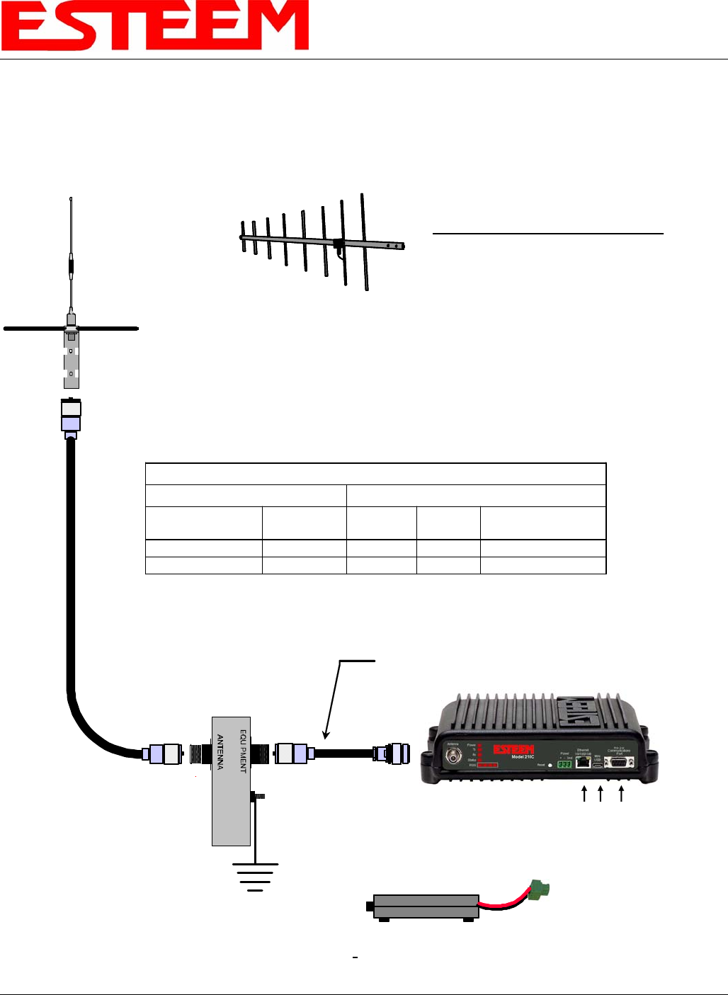
ETHERNET INTERFACE
The ESTeem Model 195C/M’s Ethernet Port is a Full and Half-Duplex Auto-negotiation interface supporting 10 Mbps, 100 Mbps
and 1Gbps (10/100/1000BaseT). The port is compatible with TIA/EIA-568B cable configuration (Figure 1).
Figure 1: Ethernet Pin Layout
RS-232C DATA PORT CONFIGURATION
The ESTeem Model 195C/M has a 9-pin RS-232C data interface on the front panel. See Chapter 6 for further information on
serial data port configuration. To interface the 195C/M to the serial port on the computer, you need serial cable with the following
pin-out:
ESTeem Model 195C/M
RS-232C Port Pin-Out Table
Function
DB-9
Pin No.
Data Set Ready (DSR) 6
Data Carrier Detect (DCD) 1
Data Terminal Ready (DTR) 4
Signal Ground (GND) 5
Receive Data (RxD) 2
Transmit Data (TxD) 3
Clear to Sent (CTS) 8
Request to Sent (RTS) 7
APPENDIX C
RADIO CONFIGURATION
Revised: 26 Sep 2013 APX C-1 EST P/N AA107-195CM
195C/M FREQUENCIES OF OPERATION
In a wireless Ethernet network all of the ESTeem Model 195C/M must be set to the same radio frequency of operation. The
frequency of operation is selectable when configuring the mode of operation of the 195C/M (reference Chapter 3).
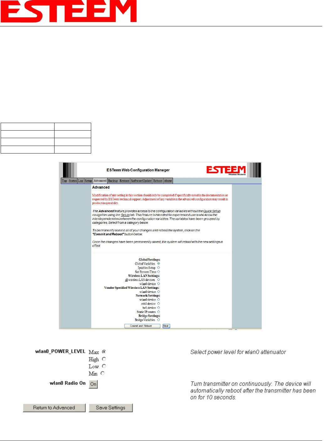
SETTING RF POWER LEVEL
The ESTeem Model 195C/M peak power is adjustable in output power from the advanced configuration menu. The output power
is adjusted on the Advanced Menu>Wireless LAN Settings>Wlan0 Device screen (Figure 4) of the Web Configuration
Manager. Select the value and press the Save Settings button.
Max (Maximum) Full Power
Hi (High) 75% Power
Lo (Low) 50% Power
Min (Minimum) 25% Power
Figure 1: Advanced Global Variables
Figure 2: Power Level Settings
APPENDIX D
TROUBLESHOOTING
Revised: 26 Sep 13 APX D-1 EST P/N AA107-195CM
TESTING COMMUNICATION LINK
After you have configured at least two of the Model 195C/M
wireless Ethernet modems for operation, you can verify
communication with each the following steps:
Status LED
Solid Red on Link
Figure 1: Connection Status Light
Status Light
The quickest source of link status is to view the Status Light
on the face of the 195C/M (Figure 1). If the Status light is
solid, the Model 195C/M has a connection to another Model
195C/M listed in the Peer Table.
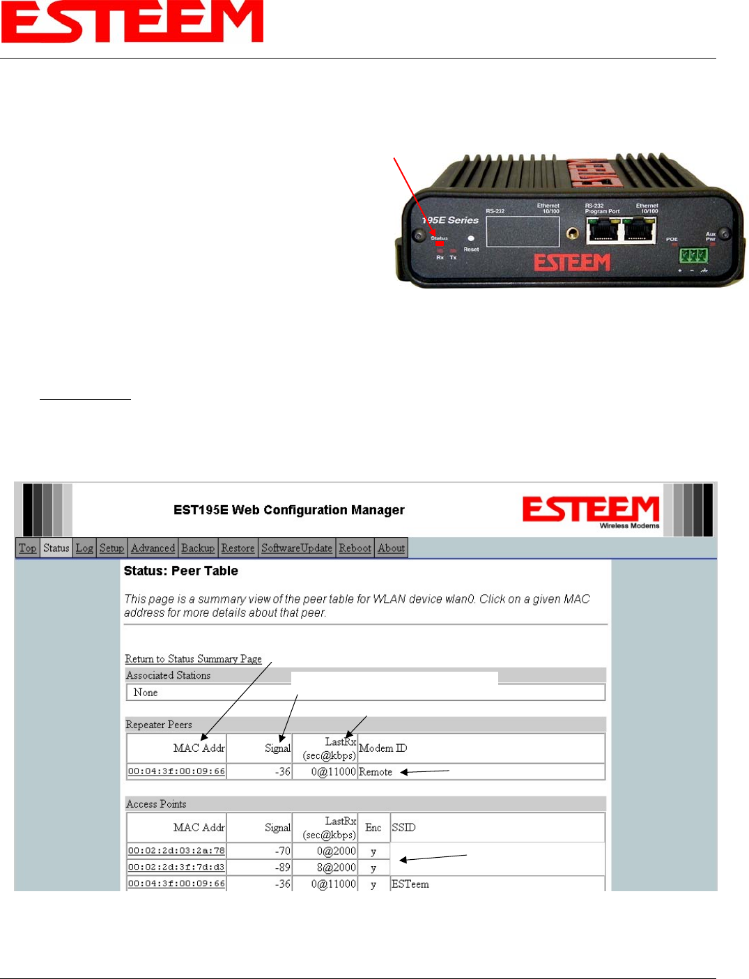
Status Screen/Peer Table
To view detailed information on the status of the communication link (such as connection speed, signal strength and last update
time) you can open the Status Screen from the Web Interface. After press the Status tab at the top of the screen the Status:
Summary will be displayed showing the status of all ports and memory in the 195C/M. Under the Wireless Status heading click
on the View Peer Table (Figure 2). The Peer Table will list all other Wifi (195C/Mg and 195C/Ma only) or mobile client wireless
activity seen by the 195C/M and how it is classified.
Note: The data rate displayed is not necessarily indicative of the RF data rate between the ESTeems. The rate show in the
Repeater Peer table will be the last RF packet, which could consist of either data, repeater beacon or network
probes.
Opposite Modem’s Wireless MAC
Receive Signal Strength (dBm)
Last Packet Received
Peer Modem ID
Other Access Points
Figure 2: Repeater Peer Table

APPENDIX D
TROUBLESHOOTING
Revised: 26 Sep 13 APX D-2 EST P/N AA107-195CM
Repeater Peers - The Peer Table will display all connected 195C/Ms configured to repeat to this ESTeem by their Wireless
(WLAN) MAC address.
Received Signal Strength – This is the first of the two numbers listed in the block. This signal strength value is listed in dBm.
Last RX – This is the time of the last received data packet. When monitoring the status menu, it is important to note the time the
last transmission was updated so you are not looking at “stale” data.
Current Data Rate – This is the current speed the last data packet received by the Model 195C/M. This may not be the data rate
between the radio modems. Note that the speed is listed in kbps, so that 11000 kbps is equal to 11 Mbps.
Note: The ESTeem Model 195C/M uses spread spectrum technology that analyzes each data packet for signal strength and data
quality (strength vs. noise). The higher your signal, the mare background noise you can sustain without causing
degradation in the data transfer. This is also true for lower signal strengths with a very low background noise. These
values are provided for guidance and if you have any questions about the values in your application, please contact
ESTeem Customer Support at 509-735-9092 or e-mail your application to support@esteem.com.
Modem ID – This is Modem ID for the opposite repeater peer.
APPENDIX D
TROUBLESHOOTING
Revised: 26 Sep 13 APX D-3 EST P/N AA107-195CM
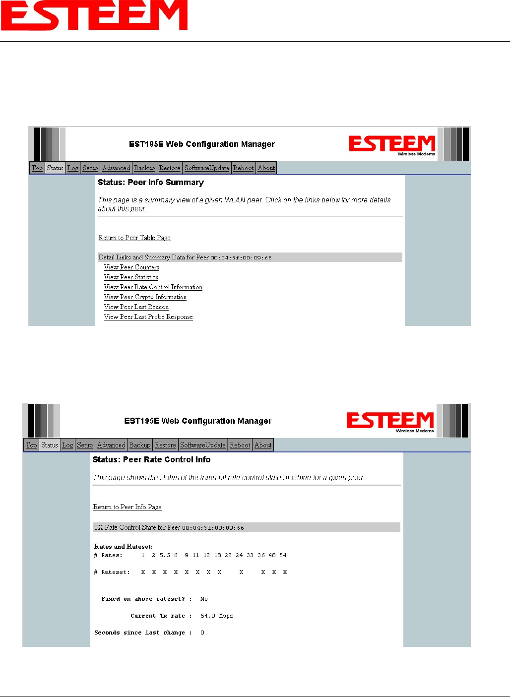
Viewing RF Data Rates
The value shown on the Peer Status Screen for data rate may not be the actual rate of the RF link. To view the link information,
click on the Opposite Modems WLAN MAC address in the Repeater Peer list (Figure 2) and further link status information will be
displayed (Figure 3).
Figure 3: Peer Summary Table
Once loaded, click on View Peer Rate Control Information. (Figure 4)
The value of the Current TX rate is the RF data rate between the two ESTeem Model 195C/M.
Figure 4: Rate Control Information
APPENDIX D
TROUBLESHOOTING
Revised: 26 Sep 13 APX D-4 EST P/N AA107-195CM
SIGNAL STRENGTH VS DATA RATE
The average signal strength required to maintain a specific data rate will vary by ESTeem 195C/M model and bandwidth. To
review the required signal level and its effect from distance and hardware selected, please use the ESTeem RF Design program
available from our web site (www.esteem.com). Please note that the data rates can be greatly affected by overall activity on the
radio channel and the total background noise. These values should be used as a guide, but testing after installation is required.
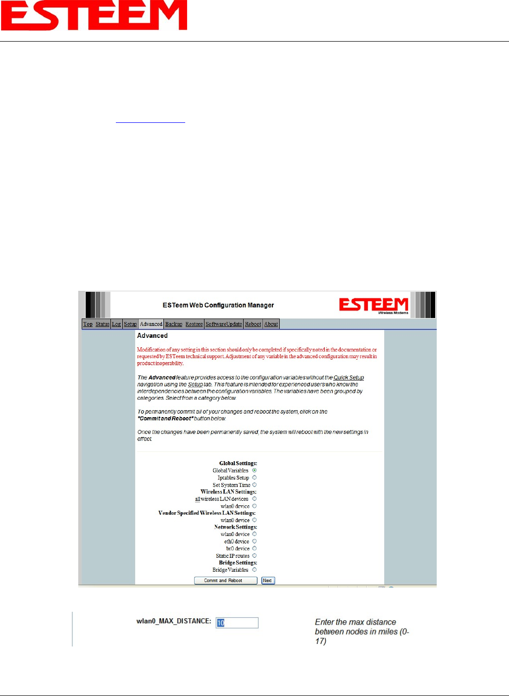
LONG RANGE POINT TO POINT APPLICATIONS
The factory configuration on the 195C/M is optimized for distances up to 10 miles. If your application has an RF link with a range
greater than 10 miles, you will need to set the maximum range value on both ESTeem 195C/M’s on this communication link. To
access the Maximum Distance value select Advanced from the top Menu then Wireless LAN Settings>wlan0 device and press
the Next button (Figure 5).
Scroll down the menu list until you find the Maximum Distance variable (Figure 6). Enter the maximum distance of the
connection in miles. At the bottom of the screen press Return to Advanced button and then Commit and Reboot button (Figure
5) to save the information.
Figure 5: Advanced Features Screen
Figure 6: Maximum Distance Value Entry

APPENDIX D
TROUBLESHOOTING
Revised: 26 Sep 13 APX D-5 EST P/N AA107-195CM
TROUBLESHOOTING TIPS
General (Applicable to All Modes of Operation)
Where do I find the latest firmware version number? – We have the latest version number of the Model 195C/M firmware listed
on the ESTeem Web site (www.esteem.com) under the Model 195C/M product page.
How and when do I update the Model 195C/M firmware? - You should only update the Model 195C/M firmware if you are
having a specific problem and it is recommended that you do so by ESTeem Customer Support personnel. All the update
instructions and files are located on the ESTeem FTP site at the following address:
ftp://www.esteem.com/195C/M
Do all firmware versions have to be the same to communicate between the Model 195C/M? – It is not necessary for all the
firmware versions to be the same revision to communication, but the later version may have added features that the other versions
will not recognize.
What characters are valid for WEP Key entry? - Only the Hexadecimal characters 0-9 and A-F are valid for key entry.
What ESTeem Utility version is required to program the Model 195C/M? – The ESTeem Utility program is not required to
program the Model 195C/M. The 195C/M can be programmed using any Terminal Emulation program (such as Windows
HyperTerminal) and any web browser program.
What is the speed and duplex configuration on the Model 195C/M – The Model 195C/M is an auto-negotiation full/half-duplex
10/100 Base-T interface. Ether a cross-over or patch cable is supported.
Access Point Mode
Wireless LAN cards are not connecting – Verify that the wireless LAN cards are set to Infrastructure Mode, have a matching SSID
(or ESSIS) set the same as the Model 195C/M and that all encryption codes are the same.
My Wireless LAN card shows a solid connection, but I can not pass any data – Verify the encryption and the ACL setting on the
Model 195C/M match the wireless LAN card.
Access Point Repeater Mode
How long does it take to re-establish the Wireless Ethernet Network? - If a communication link is lost and the Wireless Network
needs to re-establish the repeater routes, the time can take up to 10 seconds.
Should the AP Repeater Mode be used on mobile equipment? - The AP Repeater mode should be used on equipment that will not
change the Repeater Route as it moves. For example, if a mobile device such as a crane can communicate directly to another
ESTeem and will not loose the link in its travel, the AP Repeater Mode could be used. If the device requires two ESTeem Model
195C/M’s (Base and Repeater) to maintain communication across its complete travel, the Station Modes should be used on the
mobile device. The problem will be in the time that the mobile ESTeem will take to transfer between the two sites. In Access
Point Repeater mode the transfer can take up to 30 seconds, while the EtherStation mode will transfer without a packet loss.
Does WEP have to be used? – The WEP does not have to be enabled for the modems to communicate, but all modems must be
configured the same way.
Correct configuration, but cannot establish communications. – In addition to the network configuration, all 195C/M modems
configured in the AP mode must share the same SSID and be on the same frequency channel. The most likely cause of the error is
the WLAN MAC address is not configured in both 195C/M’s repeater tables. If only one side is configured, everything will
appear to be correct but no communication will function.

APPENDIX D
TROUBLESHOOTING
Revised: 26 Sep 13 APX D-6 EST P/N AA107-195CM
EtherStation
How do I access the Model 195C/M web page in EtherStation Mode? The Model 195C/M does not have an active web browser
when configured in EtherStation mode. You must access the ESTeem with the ESTeem Discovery Program or through the RS-
232 port after configuration in this mode. To monitor the link status, you can use the EtherStation Status program.
What IP address do I configure the ESTeem in EtherStation mode? – The Model 195C/M will not have an IP address in
EtherStation mode.
I can not link my device into the wireless network – Verify that the MAC address of the device is exactly the same as configured
in the Model 195C/M. The MAC address must have colons between the values.
Can I connect my Model 195C/M in EtherStation mode to a HUB or Ethernet Switch? – No. The modem must be connected
directly to the Ethernet device for which it is programmed. In EtherStation mode the Model 195C/M can only service ONE
Ethernet device.
APPENDIX E
195C SPECIFICATIONS
Revised: 26 Sep 13 APX E-1 EST P/N AA107-195CM
Frequency of Operation (Software Selectable) 450 to 470 Mhz (6.25Khz / 12.5 Khz Channel Spacing)
Frequency Stability, -30C to +60C +/- 1.5ppm
RF Data Rate @ 6.25Khz channel spacing 4.8Kbps
RF Data Rate @ 12.5Khz channel spacing 9.6Kbps
Tx Output Power (Software Adjustable) 0.5 to 4 Watts
Tx Output Impedance 50 ohms
Rx Sensitivity -110 dBm
Rx Adjacent Channel Rejection > 55 dB
Modulation 4-Level GFSK
Forward Error Correction TCM, Coding Rate 3/4
Data Error Detection 32-Bit Cyclic Redundancy Check
FCC ID ENPESTEEM195C
Industry Canada Type Acceptance 2163 192 195C
LED Indicators Power (48VDC, 12V-Aux), Status Multi-Color LED (Tx, Rx, Rx-Valid, Rx-Error), RS-
232 Tx/Rx, RS-485 Tx/Rx, RS-422 Tx/Rx, Ethernet Activity / Link
Data Packet Information
Radio Addressing 1-254 Total Units, Digi-repeating allows up to 3 repeaters between end-points
Data Packet Size 1-2000 Bytes
Serial Data Interface Buffer Size 8Kbytes Tx / 8Kbytes Rx
Data Retry Software Adjustable
Power Requirements
Receive / Without Ethernet Link 120 ma @ 12 VDC
Receive / With Ethernet Link 160 ma @ 12 VDC
Transmit @ 4 Watts RF Output 1540 ma @ 12 VDC
External 48 VDC Power Supply, EST P/N (tba) 30 Watts, RJ-45 Connector, Cat 5 Cable (300 Ft Maximum)
External DC Power Input 10.8 to 15 VDC
Input/Output Connectors
Ethernet Port (10/100) RJ-45 Female
Serial Data Interfaces (One of four selectable) Baud Rates 2400 to 115,200
1. RS-232 Port 1 (4-Wire) Tx,Tx-Gnd,Rx,Rx-Gnd RJ-45 Female (Shared with 48VDC Port)
2. RS-232 Port 2 (With Handshaking Signals) RJ-45 Female, Optional RJ-45 To DB9, 3-Wire Adaptor Available
3. RS-485 Port RJ-45 (Shared With 4-20 mA Sensor Port)
4. RS-422 Port RJ-45 (Shared With Ethernet Port)
4-20 mA I/O RJ-45 Female (Shared With RS-485 Port)
Antenna Input/Output TNC Female Connector
External DC Input Power Mini-Combicon, 3 pin female
Serial Data Interface, Master PLC mode protocols
supported by auto-digi-repeater function Allen Bradley DF1, Opto22, Modbus RTU/ASCII, and Transparent protocols
Ethernet Interface protocols supported for remote
access via ARP proxy on Master Gateway Unit
ICMP Echo (ping), Modbus/TCP (Aux Voltage, 4-20mA readings, RSSI, MCU Core
Temperature), Remote Configuration
Ethernet Interface protocols (direct access only) Telnet, IP Configuration, Firmware upgrades
Temperature Range -30° to +60° C
Humidity 95% Non-condensing
Dimensions 1.9 in. H x 6.7 in. W x 6.2 in. L
Weight 1.25 lbs.
Product Warranty 1 Year
Outdoor Pole Mount Kit AA195PM
48 VDC Power Supply TBD
RJ-45 To DB9 Serial Adaptor TBD
RJ-45 To Terminal Block Adaptor TBD
Antennas/Surge Protectors/Cables, etc. Contact factory for various options (market@esteem.com or 509-735-9092)
Options
ESTeem 195C Specifications
Mechanical / Environmental
Protocols
Transmiter/Receiver
APPENDIX E
195C SPECIFICATIONS
Antenna Specifications
Revised: 26 Sep 13 APX E-2 EST P/N AA107-195CM
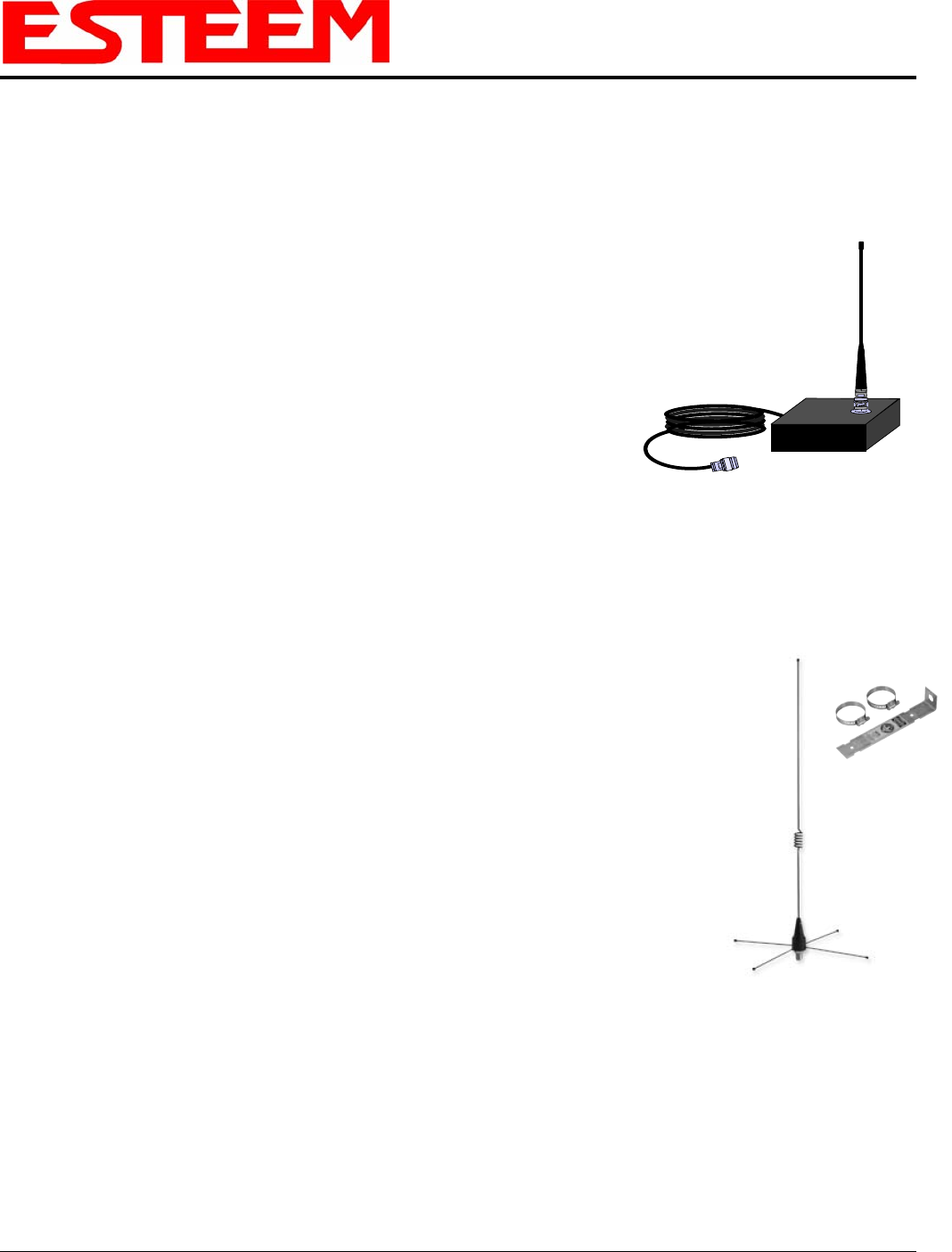
Model No: AA19C
Antenna Type: Omni-Directional, ½ Wave
Applications: Mobile Mount.
Frequency: 450 to 470 MHz - AA19C
400 to 420 MHz - AA19F
Polarization: Vertical
Impedance: 50 ohms
Gain: 2 db.
VSWR: < 2 to 1
Front To Back Ratio: n/a
Horizontal Beamwidth: n/a
Vertical Beamwidth: 60 degrees
Antenna Material: Rubber duck whip.
Mounting Hardware: Magnetic base. Model AA19C
Antenna Connector: TNC with 12 feet integral RG-58 cable.
Antenna Envelope: 16 in. length. Magnetic base 3.5 in. by 3 in by 1 in.
Weight: 1 lb. 5 oz.
Model No: AA20C.1
Antenna Type: Omni-Directional, DC grounded, Collinear 5/8 wave
over 1/2 wave.
Model AA20C.1
Applications: Fixed base or mobile mounting. L shaped mounting bracket
may be removed for panel mounting. Ground plane radials
may be removed depending on application.
Frequency: 450 to 470 MHz - AA20C.1
Polarization: Vertical
Impedance: 50 ohms
Gain: 4.5 dB.
VSWR: < 1.5
Front To Back Ratio: n/a
Horizontal Beamwidth: n/a
Vertical Beamwidth: 30 degrees
Antenna Material: Stainless steel whip and ground plane radials. All other
hardware anodized metal.
Mounting Hardware: Stainless steel clamps for mounting to ¾ in. to 1 /2 in. pipe
with right angle mount or direct mount.
Antenna Connector: N-Type Female
Antenna Envelope: 37 ½ in. length by 16 in width with ground plane radials.
Weight: 2 lbs.

APPENDIX E
195C SPECIFICATIONS
Antenna Specifications
Revised: 26 Sep 13 APX E-3 EST P/N AA107-195CM
Model AA202C/F
Model No: AA202C & AA202F
Antenna Type: Directional, DC grounded, 5 element yagi.
Applications: Fixed base.
Frequency: 450 to 470 MHz - AA202C
400 to 420 MHz - AA202F
Polarization: Vertical or Horizontal
Impedance: 50 ohms
Gain: 10 dB
VSWR: < 1.5
Front To Back Ratio: 20 dB
Horizontal Beamwidth: 59 degrees
Vertical Beamwidth: 53 degrees
Antenna Material: High strength aluminum with gold chromate finish.
Mounting Hardware: Heavy duty U bolts for mounting up to 2 1/8 in. pipe with right angle mount or direct panel
mount.
Antenna Connector: N-Type Female
Maximum Power Input: 300 Watts
Antenna Envelope: 34.5 in. length by 13.25 in. width
Windload (RWV): 100 mph
Weight: 1.68 lbs.

APPENDIX G
195M SPECIFICATIONS
Revised: 1 Oct 13 APX G-1 EST P/N AA107-195CM
Frequency of Operation (Software Selectable) 150 to 174 Mhz (6.25Khz / 12.5 Khz Channel Spacing)
Frequency Stability, -30C to +60C +/- 1.5ppm
RF Data Rate @ 6.25Khz channel spacing 4.8Kbps
RF Data Rate @ 12.5Khz channel spacing 9.6Kbps
Tx Output Power (Software Adjustable) 0.5 to 4 Watts
Tx Output Impedance 50 ohms
Rx Sensitivity -110 dBm
Rx Adjacent Channel Rejection > 55 dB
Modulation 4-Level GFSK
Forward Error Correction TCM, Coding Rate 3/4
Data Error Detection 32-Bit Cyclic Redundancy Check
FCC ID ENPESTEEM195M
Industry Canada Type Acceptance 2163 192 195M
LED Indicators Power (48VDC, 12V-Aux), Status Multi-Color LED (Tx, Rx, Rx-Valid, Rx-Error), RS-
232 Tx/Rx, RS-485 Tx/Rx, RS-422 Tx/Rx, Ethernet Activity / Link
Data Packet Information
Radio Addressing 1-254 Total Units, Digi-repeating allows up to 3 repeaters between end-points
Data Packet Size 1-2000 Bytes
Serial Data Interface Buffer Size 8K bytes Tx / 8K bytes Rx
Data Retry Software Adjustable
Power Requirements
Receive / Without Ethernet Link 120 ma @ 12 VDC
Receive / With Ethernet Link 160 ma @ 12 VDC
Transmit @ 4 Watts RF Output 1540 ma @ 12 VDC
External 48 VDC Power Supply, EST P/N (tba) 30 Watts, RJ-45 Connector, Cat 5 Cable (300 Ft Maximum)
External DC Power Input 10.8 to 15 VDC
Input/Output Connectors
Ethernet Port (10/100) RJ-45 Female
Serial Data Interfaces (One of four selectable) Baud Rates 2400 to 115,200
1. RS-232 Port 1 (4-Wire) Tx,Tx-Gnd,Rx,Rx-Gnd RJ-45 Female (Shared with 48VDC Port)
2. RS-232 Port 2 (With Handshaking Signals) RJ-45 Female, Optional RJ-45 To DB9, 3-Wire Adaptor Available
3. RS-485 Port RJ-45 (Shared With 4-20 mA Sensor Port)
4. RS-422 Port RJ-45 (Shared With Ethernet Port)
4-20 mA I/O RJ-45 Female (Shared With RS-485 Port)
Antenna Input/Output TNC Female Connector
External DC Input Power Mini-Combicon, 3 pin female
Serial Data Interface, Master PLC mode protocols
supported by auto-digi-repeater function Allen Bradley DF1, Opto22, Modbus RTU/ASCII, and Transparent protocols
Ethernet Interface protocols supported for remote
access via ARP proxy on Master Gateway Unit
ICMP Echo (ping), Modbus/TCP (Aux Voltage, 4-20mA readings, RSSI, MCU Core
Temperature), Remote Configuration
Ethernet Interface protocols (direct access only) Telnet, IP Configuration, Firmware upgrades
Temperature Range -30° to +60° C
Humidity 95% Non-condensing
Dimensions 1.9 in. H x 6.7 in. W x 6.2 in. L
Weight 1.25 lbs.
Product Warranty 1 Year
Outdoor Pole Mount Kit AA195PM
48 VDC Power Supply TBD
RJ-45 To DB9 Serial Adaptor TBD
RJ-45 To Terminal Block Adaptor TBD
Antennas/Surge Protectors/Cables, etc. Contact factory for various options (market@esteem.com or 509-735-9092)
Options
ESTeem 195M Specifications
Mechanical / Environmental
Protocols
Transmiter/Receiver
APPENDIX F
210M SPECIFICATIONS
Antenna Specifications
Revised: 1 Oct 13 APX G-2 EST P/N AA107-195CM
Model No: AA19M
Antenna Type: Omni-Directional, ½ Wave over ¼ Wave
Model AA19M
Applications: Mobile Mount.
Frequency: 150-174 MHz
Polarization: Vertical
Impedance: 50 ohms
Gain: Unity
VSWR: < 1.5 to 1
Front To Back Ratio: n/a
Horizontal Beamwidth: n/a
Vertical Beamwidth: 60 degrees
Antenna Material: Rubber duck whip.
Mounting Hardware: Magnetic base.
Antenna Connector: TNC with 12 feet integral RG-58 cable.
Antenna Envelope: 11 in. length. Magnetic base 3.5 in. by 3 in by 1 in.
Weight: 1 lb. 5 oz.
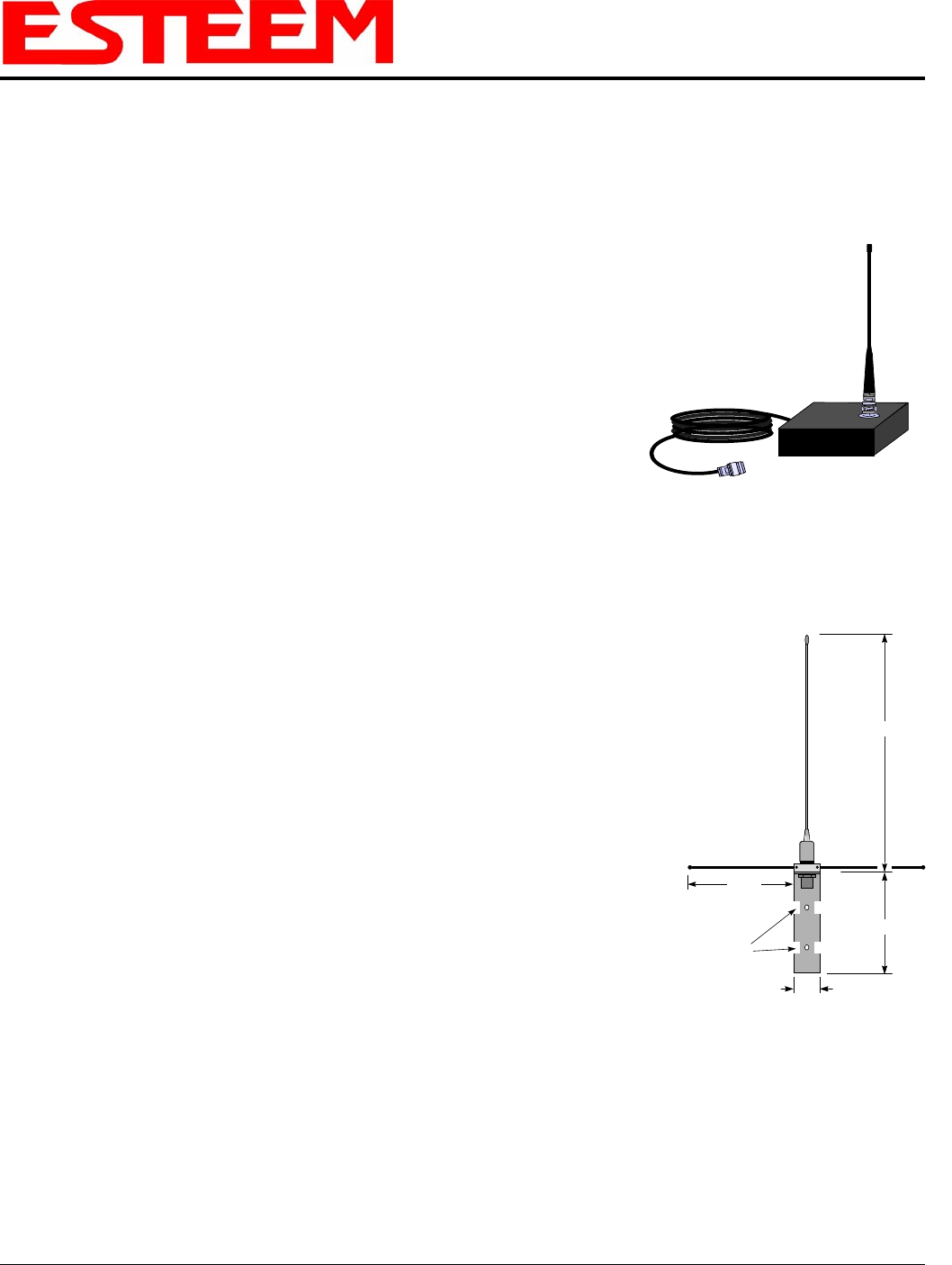
Model No: AA20M
1.5 in.
9 in.
Drawing Not To Scale
5/16 in.
Diameter
52 in.
21 in.
Model AA20M
Antenna Type: Omni-Directional, DC grounded, Collinear 5/8 wave
Applications: Fixed base or mobile mounting. L shaped mounting
bracket may be removed for panel mounting. Ground
plane radials may be removed depending on application.
Frequency: 150 to 175 MHz
Polarization: Vertical
Impedance: 50 ohms
Gain: 3.0 dBd with ground plane radials
VSWR: < 1.5
Front To Back Ratio: n/a
Horizontal Beamwidth: n/a
Vertical Beamwidth: 60 degrees
Antenna Material: Stainless steel whip and ground plane radials. All other
hardware anodized metal.
Mounting Hardware: Stainless steel clamps for mounting to ¾ in. to 1.5 in.
pipe with right angle mount or direct mount.
Antenna Connector: UHF Female (SO-239)
Antenna Envelope: 61 in. length by 43.5 in. width with ground plane radials
Weight: 2 lbs.

APPENDIX F
210M SPECIFICATIONS
Antenna Specifications
Revised: 1 Oct 13 APX G-3 EST P/N AA107-195CM
Model No: AA202M
Antenna Type: Directional, 6 element yagi.
Applications: Fixed base mounting.
Frequency: 150 to 174 MHz
Polarization: Vertical or Horizontal
Impedance: 50 ohms
Gain: 8 dBd
VSWR: < 1.2:1
Front To Back Ratio: 12-18 dB
Horizontal Beamwidth: 80 degrees
Vertical Beamwidth: 58 degrees
Antenna Material: .250” – 6061-T6 Aluminum
Mounting Hardware: Heavy duty U bolts for mounting up
to 2 1/8 in. pipe with right angle mount or direct panel mount.
Model AA202M
Antenna Connector: N-Type Female
Maximum Power Input: 150 Watts
Antenna Envelope: 61 in. length by 41 in. width
Wind Surface Area (sqr. ft) 0.82
Windload (RWV): 100 mph
Weight: 5 lbs.