Electronic Systems Technology ESTEEM195C 450-470MHz Narrow-band UHF modem User Manual ESTEEM USERS MANUAL
Electronic Systems Technology 450-470MHz Narrow-band UHF modem ESTEEM USERS MANUAL
Contents
- 1. User Manual Part 1
- 2. User Manual Part 2
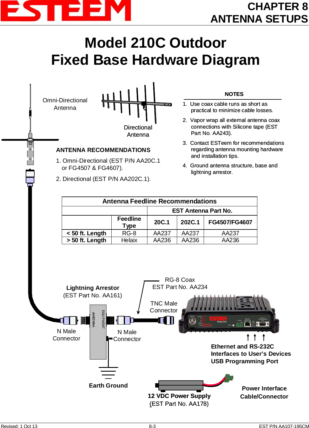
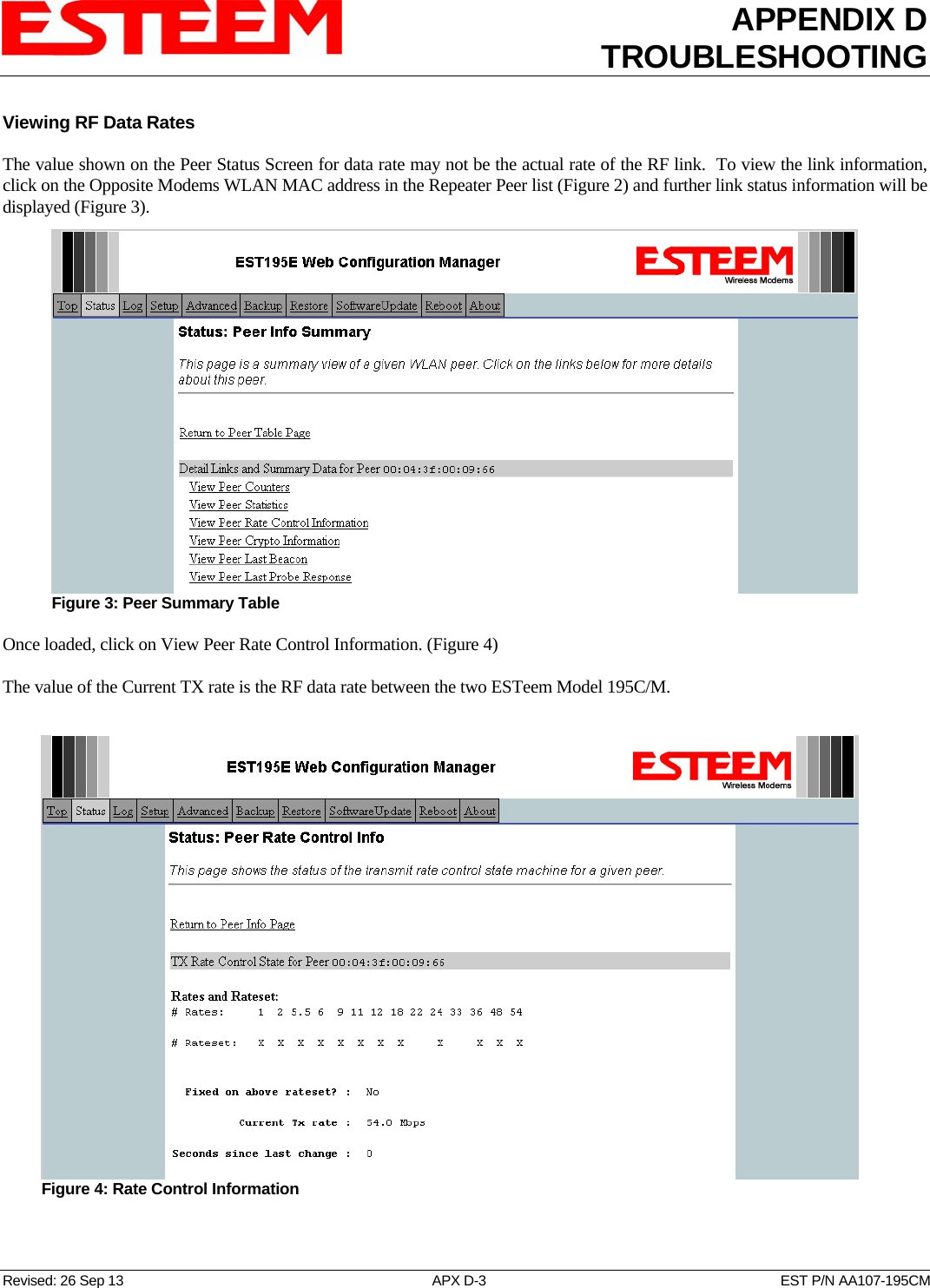
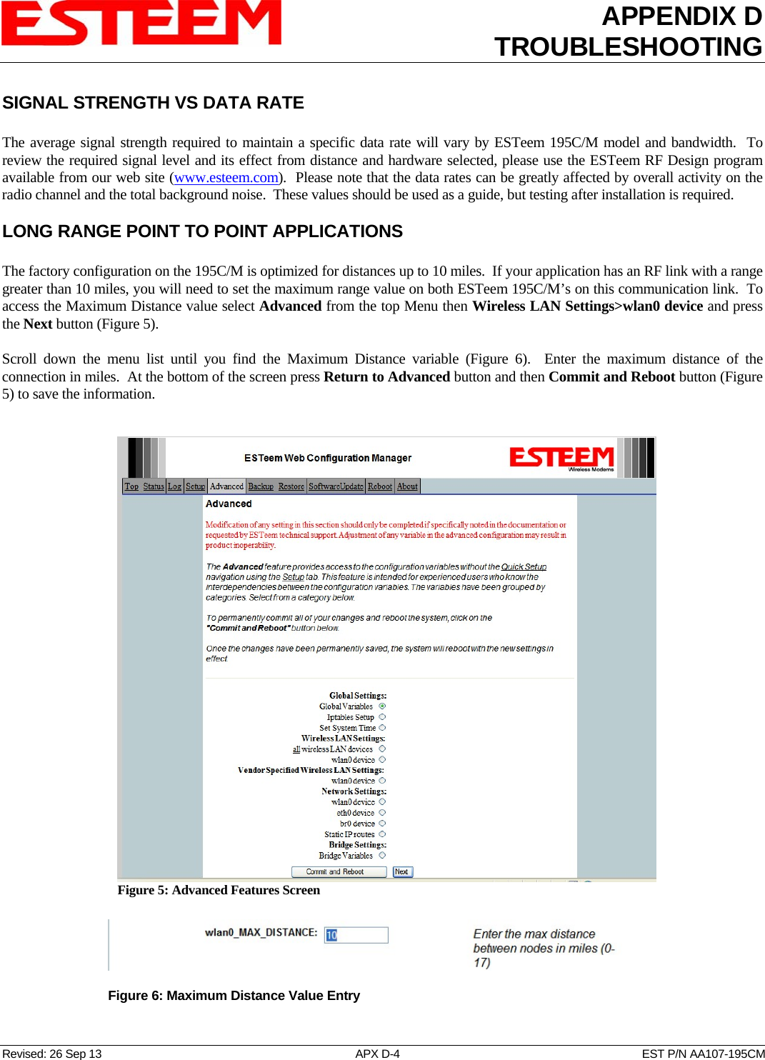
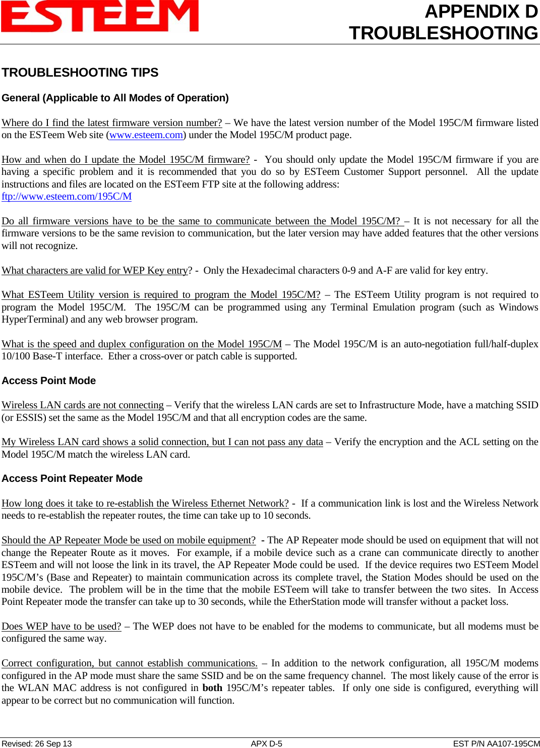
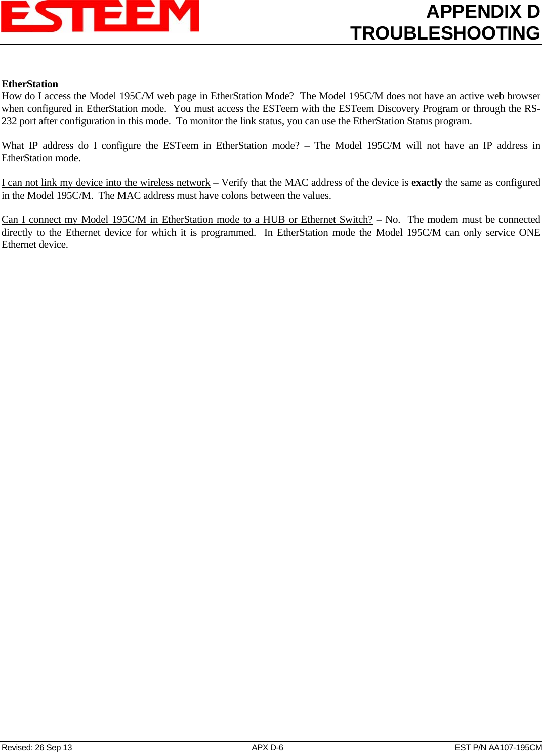
User Manual Part 2