Electronic Systems Technology ESTEEM195EA Wireless LAN transceiver User Manual CHAPTER 2
Electronic Systems Technology Wireless LAN transceiver CHAPTER 2
Contents
- 1. User Manual
- 2. User Manual Appendix A
- 3. User Manual Appendix B
- 4. Antenna Setup
Antenna Setup
CHAPTER 8
ANTENNA SETUPS
Revised: 27 Jan 12 8-1 EST P/N AA107A
ANTENNA AND CABLE CONFIGURATIONS
Warning: Only the tested cable lengths and antennas provided by EST meet the FCC and DOC maximum peak output power
requirements. Any other combination of antennas or coax cables is not authorized.
EST offers different types of antennas for both indoor and outdoor configurations. This device has been designed to operate with
the antennas listed below, and having a maximum gain of 22 dBi. Antennas not included in this list or having a gain greater than
22dBi are strictly prohibited for use with this device. The required antenna impedance is 50 ohms.
Part Number: AA20DMa
Omni-directional direct mount antenna, 4.5 dBi gain.
Indoor and outdoor applications.
There must be a minimum separation distance of 23
cm. from the antenna to the user. See Warnings.
Part Number: AA20Ea
Omni-directional external pole mount antenna, 10 dBi
gain with 18 inch integral feedline and connector.
Outdoor applications.
There must be a minimum separation distance of 23
cm. from the antenna to the user. See Warnings.
Part Number: AA205Ea
Directional linear panel, pole mount antenna, 22 dBi
gain with 18 inch integral feedline, bandpass filter and
connector.
Point to point and point to multi-point outdoor
applications.
There must be a minimum separation distance of 50
cm. from the antenna to the user. See Warnings.
This radio transmitter (ESTeem 195Ea - 2163A-195EA) has been approved by Industry Canada to operate with the antenna types
listed above with the maximum permissible gain and required antenna impedance for each antenna type indicated. Antenna types
not included in this list, having a gain greater than the maximum gain indicated for that type, are strictly prohibited for use with this
device.
(Le présent émetteur radio (ESTeem 195Ea – 2163A-195EA) a été approuvé par Industrie Canada pour fonctionner avec les types
d'antenne énumérés au-dessous et ayant un gain admissible maximal et l'impédance requise pour chaque type d'antenne. Les types
d'antenne non inclus dans cette liste, ou dont le gain est supérieur au gain maximal indiqué, sont strictement interdits pour
l'exploitation de l'émetteur.)
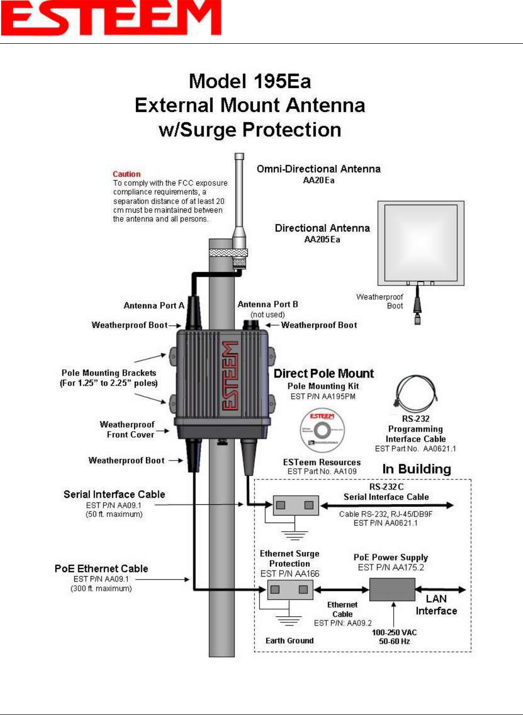
Antenna
Port A
Warnings:
Only pre-made coax cables from the factory used in
conjunction with either the omni-directional and
directional antennas meet all FCC Section 15.247(b)
EIRP maximum power requirements.
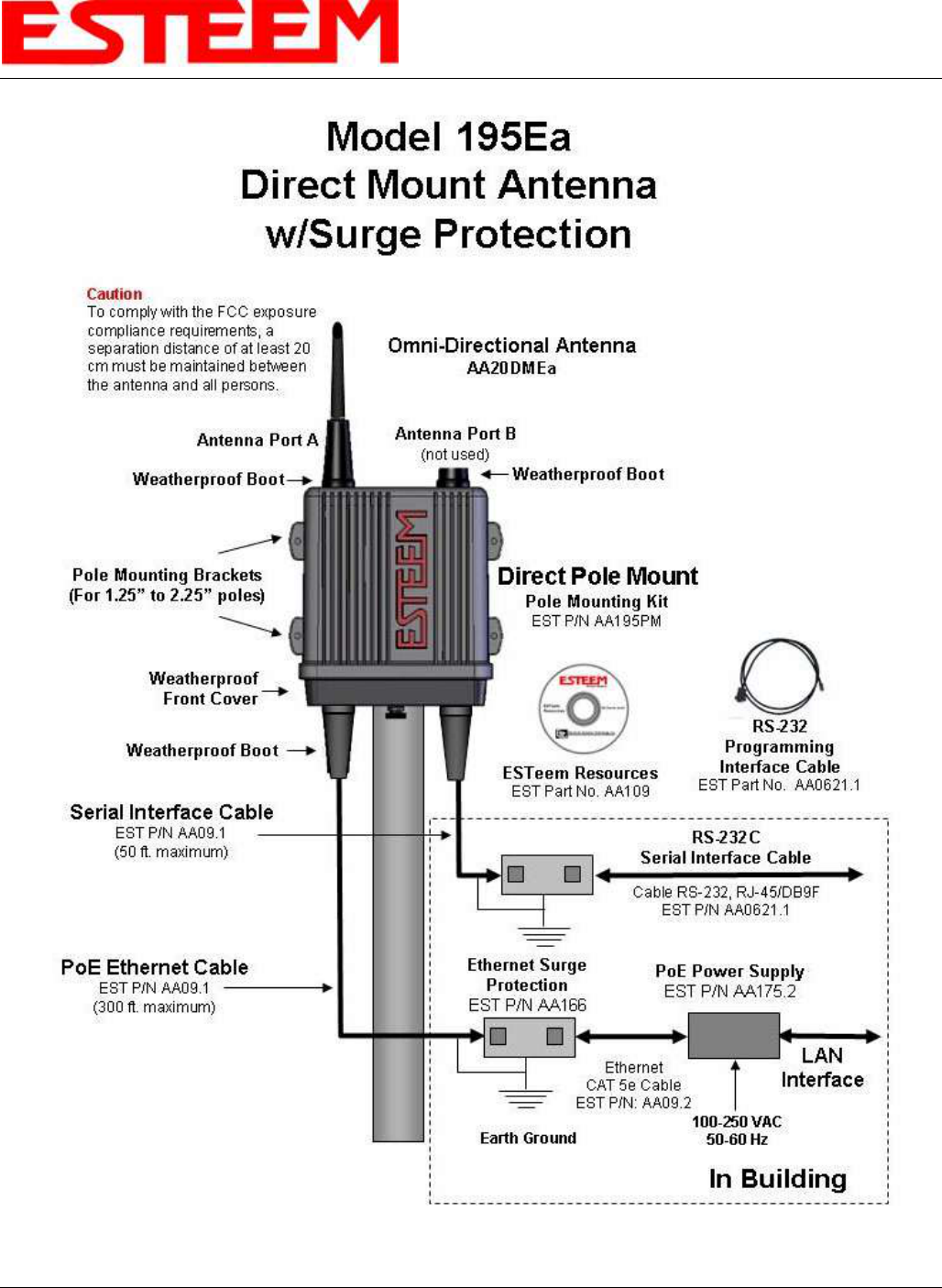
To comply with the FCC exposure compliance
requirements, a separation distance of at least 20 cm
must be maintained between the antenna and all persons.
CHAPTER 8
ANTENNA SETUPS
Revised: 27 Jan 12 8-2 EST P/N AA107A
ASSEMBLING THE AA195PM TWO HOLE OUTDOOR POLE MOUNTING KIT
The AA195PM mounting kit contains everything required for pole mounting and weatherproofing the ESTeem Model 195E for
outdoor installations. The 195E with AA195PM mounting kit can be directly mounted to a round pole from 1.25” to a diameter of
2.25” OD. Any mounting structure greater than 2” requires hose clamp strapping run through the Pole Mount Brackets. The
mounting kit requires the following assembly:
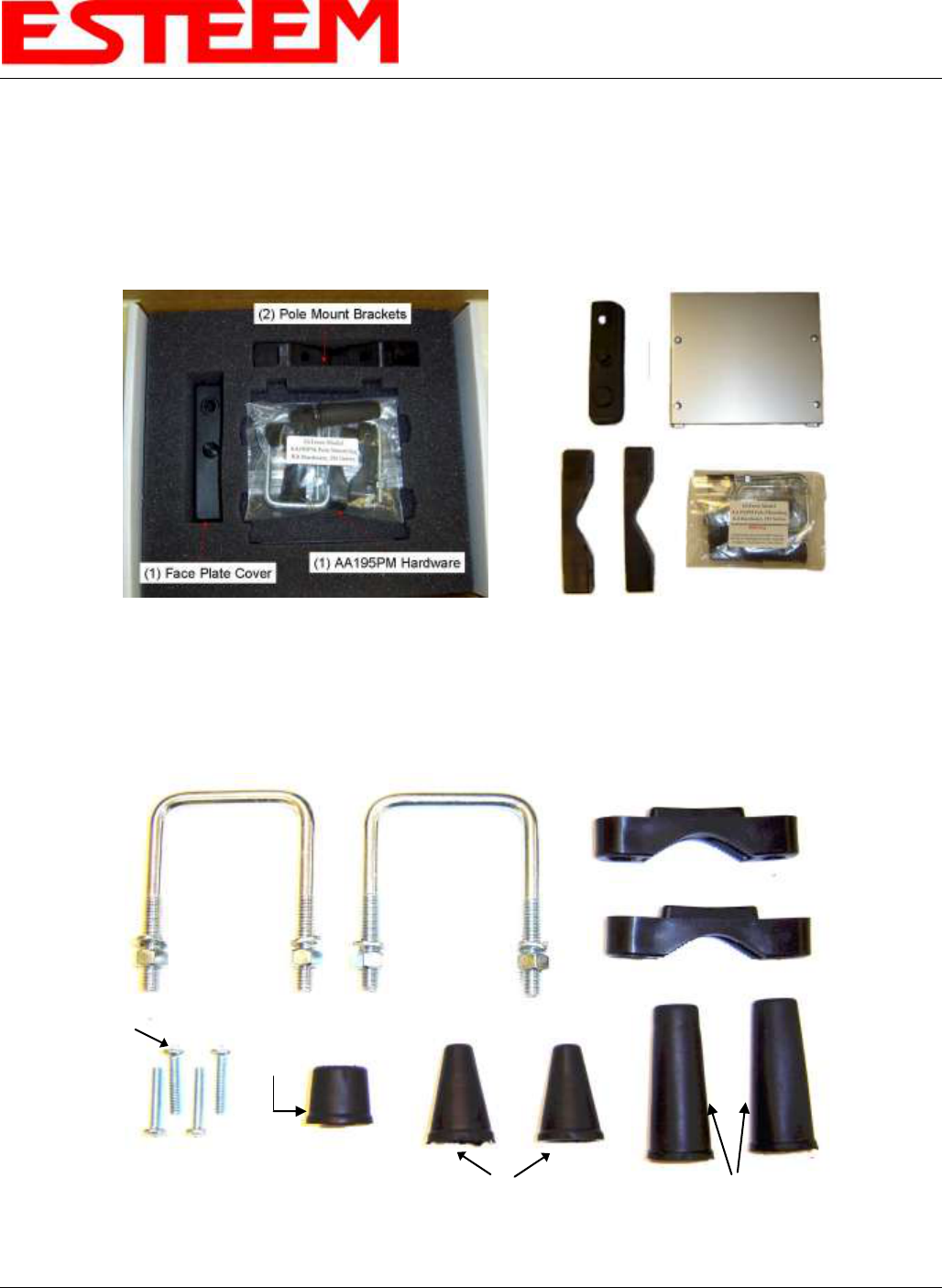
1. If you purchased an AA195PM mounting kit with your Model 195E, the kit will be packed in the same packing box as the
ESTeem (Figure 1).
2. Remove and inventory the two (2) Pole Mounting Brackets, one (1) Two-Hole Face Plate Cover (with single port cover
installed), one (1) Heat Shield and (1) AA195PM Hardware bag from the packing box (Figure 1). Report any missing or
damaged items to ESTeem Customer Support (509-735-9092 Phone) as soon as possible for replacement.
Figure 1: Packet Box Contents
Figure 2: AA195PM Hardware Contents
(2) Square Bend U-Bolts with Hardware
(2) Pole Mount Clamps
(4) 10-24 Pan Screws
(2) Ethernet
Cable Boot
(1) Weather Proof
Boot for Antenna
Port B (if not used)
(2) Direct Mount Antenna Boots for ESTeem
Approved Direct Mount Antenna Only
CHAPTER 8
ANTENNA SETUPS
Revised: 27 Jan 12 8-3 EST P/N AA107A
3. Inventory the AA195PM Hardware bag for all the components listed in Figure 2.
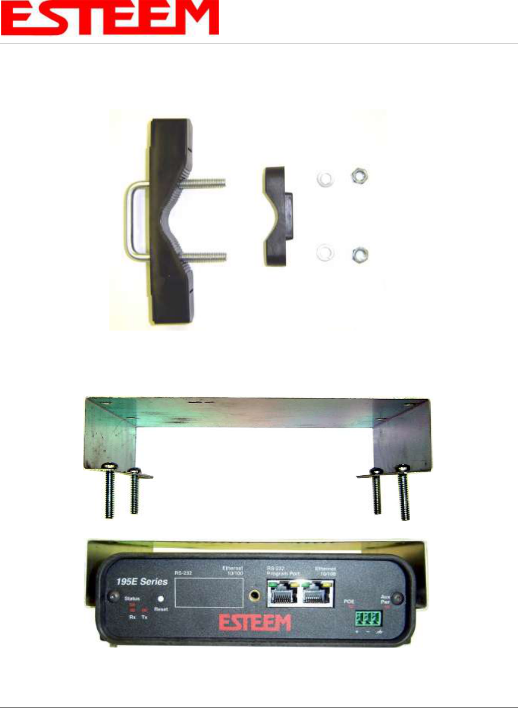
4. Assemble the two Pole Mounting Brackets with the included U-bolts, hardware and Pole Mount Clamps. Reference Figure 3.
5. Place the four supplied 10-24 x 1” Phillips Pan Head screws through the mounting holes of the Heat Shield and attach to the to
the top of the ESTeem 195E (Figure 4).
Figure 3: Pole Mount Assembly
Figure 4: Heat Shield Attachment
CHAPTER 8
ANTENNA SETUPS
Revised: 27 Jan 12 8-4 EST P/N AA107A
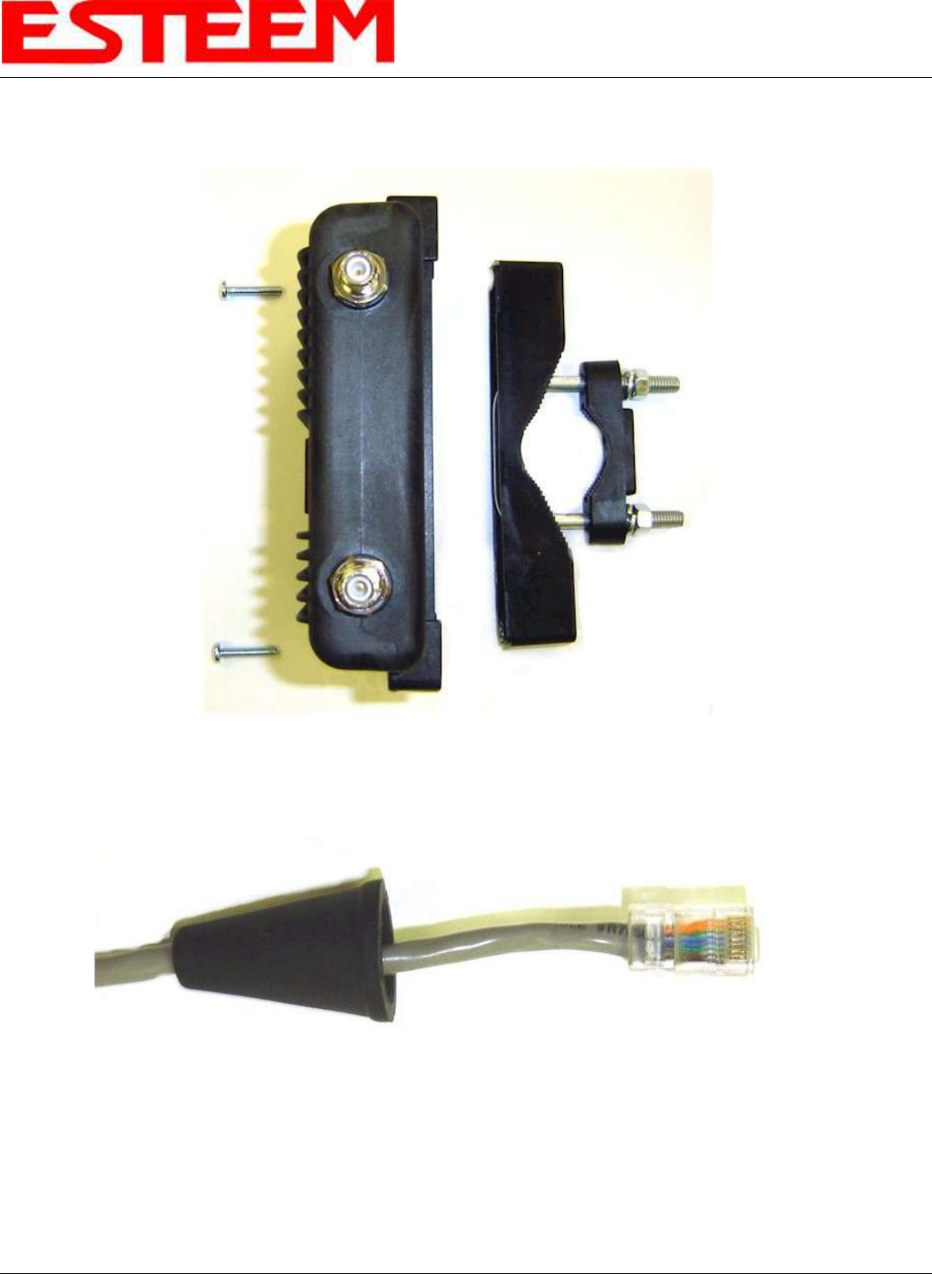
6. Attach the two Pole Mounting Brackets to the ESTeem Model 195E with the 10-24 x 1” Phillips Pan Head screws through the
top of the heat shield. Reference Figure 5 (Heat Shield removed for detail).
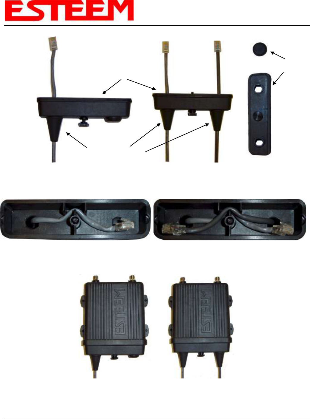
7. Assemble the outdoor rated CAT-5e Ethernet cable (Not Provided) with the supplied Ethernet Cable Boot (Figure 6).
8. Feed the CAT-5e Ethernet connector(s) through the Face Plate Cover and secure the Ethernet Cable Boot to the cover.
Reference Figure 7. NOTE: The Ethernet cable boot must be installed before the RJ-45 end is installed. If using the ESTeem
AA09.1 outdoor Ethernet cable, verify that the Ethernet cable boot end is routed toward the ESTeem 195E.
Figure 5: Pole Mount Connection to Case
(Heat Shield Removed for Detail)
Ethernet Cable Boot
Figure 6: Ethernet Cable Assembly
CHAPTER 8
ANTENNA SETUPS
Revised: 27 Jan 12 8-5 EST P/N AA107A
9. Route the CAT-5e Ethernet cable through the molded strain-relief fins in the Face Plate Cover (Figure 8) to secure the cable
and provide strain-relief for the connector. If a second Ethernet cable is installed, remove the second port cover and route
cable.
10. Plug the CAT-5e Ethernet cable to the Model 195E’s Ethernet port and secure the Face Plate Cover with the attached thumb
screw. Verify that the weatherproof seal on the Face Plate Cover is sealed against the outer rim of the Model 195E. Reference
Figure 9.
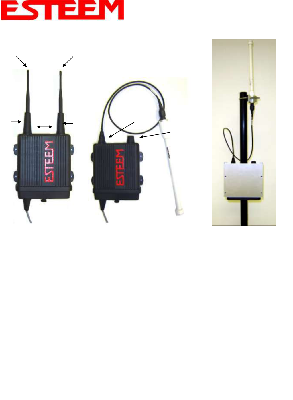
11. Attach the antenna connector boots as show in Figure 10 for either dual attached antennas or external antennas. You are now
ready to mount the ESTeem Model 195E
Figure 8: Face Plate Cover Strain Relief
Figure 9: Face Plate Cover Installed on ESTeem
Figure 7: Ethernet Cable Routing
Face Plate Cover
Ethernet Cable Boots
Second Port Cover
Remove for 2nd Cable
CHAPTER 8
ANTENNA SETUPS
Revised: 27 Jan 12 8-6 EST P/N AA107A
Caution: Outdoor mounting of the 195E requires the use of weatherproof boots. Improper installation
could result in radio failure.
Caution: Always mount the 195E vertically with the antenna ports on top.
Figure 10: Completed AA195PM Mounts
Direct Mount
Antenna Boots
Port A
EST Approved Direct Mount
Antenna Only
Port B
EST Approved External
Antenna With Factory
Installed Boot
Weather Proof Boot
NOTE: Remove Plastic
Connector Cover
Before Installation
Face Towards The
South
(North America)
CHAPTER 8
ANTENNA SETUPS
Revised: 27 Jan 12 8-7 EST P/N AA107A
195E POLE MOUNT GROUNDING PROCEEDURES
Mounting the 195E series radio modem outdoors requires proper grounding procedures to prevent damage to both the radio
hardware and the connected Ethernet and Serial peripherals. The case on the 195E series wireless modem is electrically
conductive, but the AA195 Pole Mount kit provides isolation from the connected structure. To bring the 195E case to a ground
potential with Earth ground and eliminate any static buildup on the case itself, the shield on the Ethernet cable is used to provide the
ground connection.
Outdoor Ethernet Cable
A critical component of this grounding protection system is the ESTeem AA09.1 outdoor, shielded CAT-5E Ethernet cable. This
cable provides three, necessary elements; Ethernet data, DC Power over Ethernet (PoE) applications, and a ground from the 195E
case to the AA166 surge protector. The Ethernet cable is outdoor rated and protected from UV breakdown.
Installation
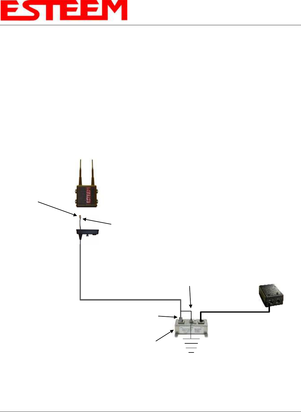
The following diagram outlines all the critical components and connections in the 195E series system. The Earth ground
connection to the surge protector must be installed to comply with local Electrical code requirements.
ESTeem Model 195E
Series Wireless Modem
ESTeem AA09.1
Outdoor, Shielded
CAT-5E Cable
(300 ft. maximum)
Metal RJ-45 Hood
(Amp 5-569530-3)
Drain Wire Soldered
To Metal RJ-45 Hood
Drain Wire With
Ring Terminal Connected
to Ground Lug
Approved Earth
Ground Connection
AA166 Ethernet
Surge Protection
Ethernet Patch Cable
(AA09.2)
Power Over Ethernet
Supply
(AA175)
Metal RJ-45 Hood
(Amp 5-569530-3)
CHAPTER 8
ANTENNA SETUPS
Revised: 27 Jan 12 8-8 EST P/N AA107A
Caution: Always mount the 195Ea vertically with the antenna ports on top.
CHAPTER 8
ANTENNA SETUPS
Revised: 27 Jan 12 8-9 EST P/N AA107A
Caution: Always mount the 195Ea vertically with the antenna ports on top.
CHAPTER 8
ANTENNA SETUPS
Revised: 27 Jan 12 8-10 EST P/N AA107A
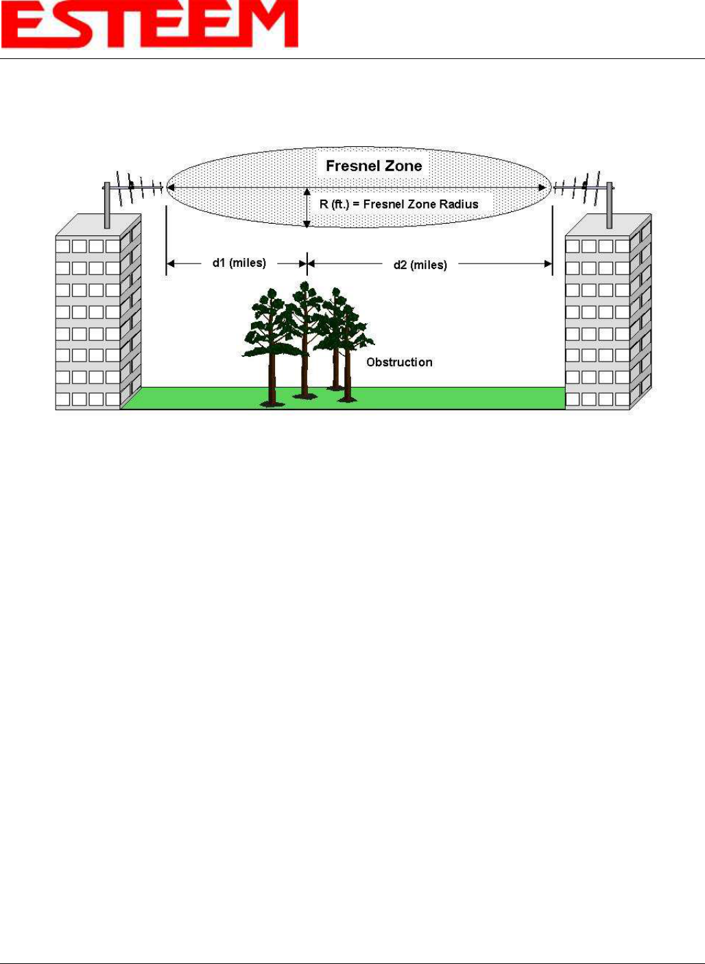
FRESNEL ZONE
The Fresnel zone shows the ellipsoid spread of the radio waves around the visual line-of-sight after they leave the antenna (see
figure above). This area must be clear of obstructions or the signal strength will be reduced due to signal blockage. Typically,
20% Fresnel Zone blockage introduces little signal loss to the link. Beyond 40% blockage, signal loss will become significant.
This calculation is based on a flat earth. It does not take into account the curvature of the earth. It is recommended for RF path
links greater than 7 miles to have a microwave path analysis done that takes the curvature of the earth and the topography of the
terrain into account.
Fresnel Zone Radius = 72.1 SQRT [(d1d2) / (F(d1 + d2)]
Units
Fresnel Zone Radius in feet.
d1 and d2 in statue miles
F in GHz