Electronic Systems Technology ESTEEM195EG 802.11b/g wireless AP User Manual Chapter 0 Front Cover 195Eg

Electronic Systems Technology 802.11b/g wireless AP Chapter 0 Front Cover 195Eg

Contents

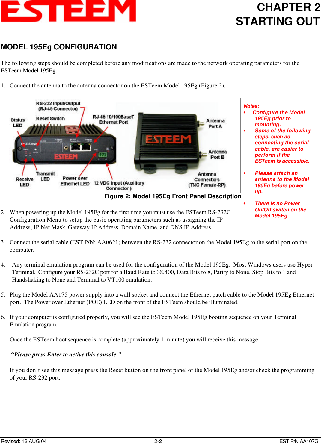
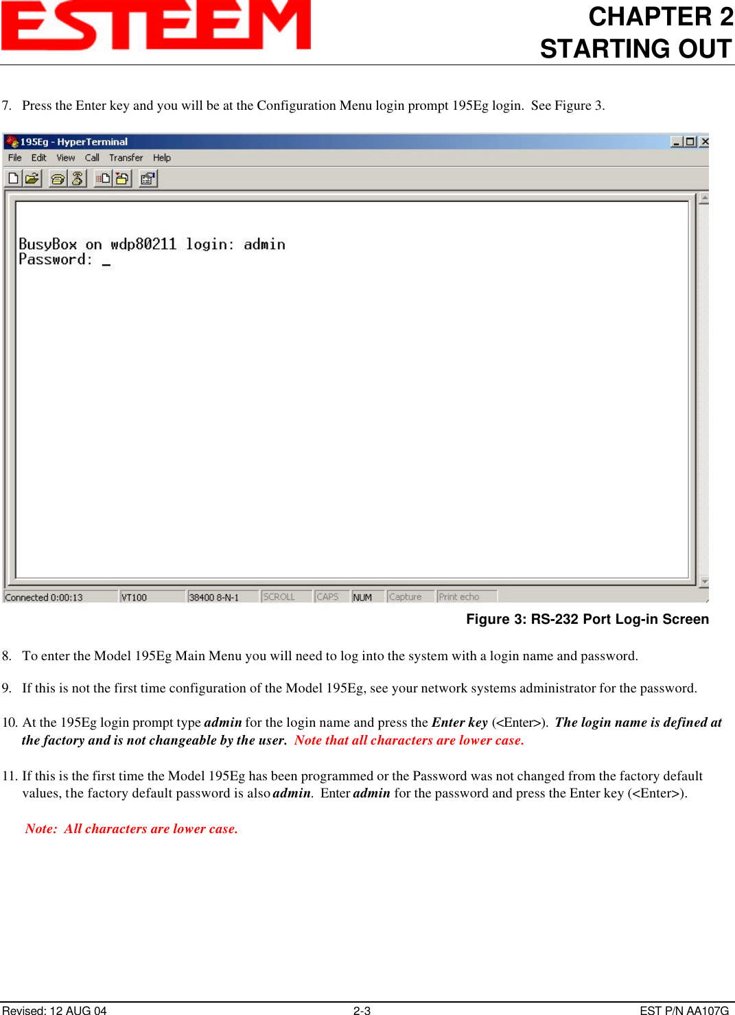
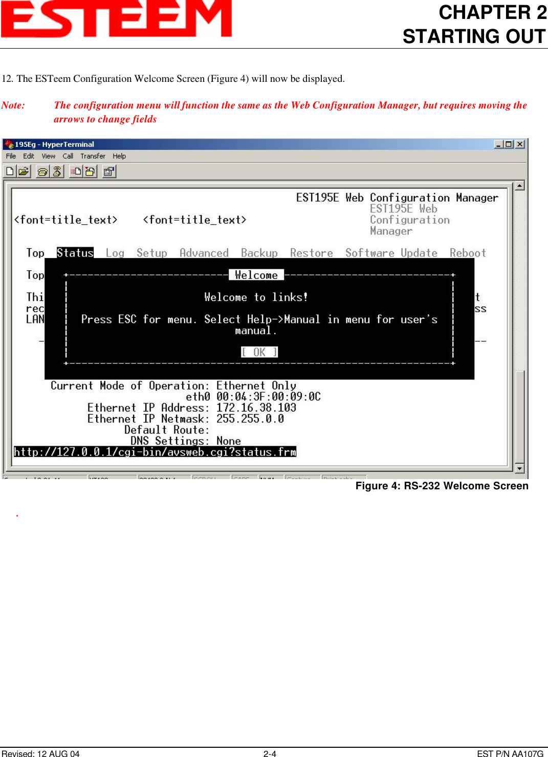
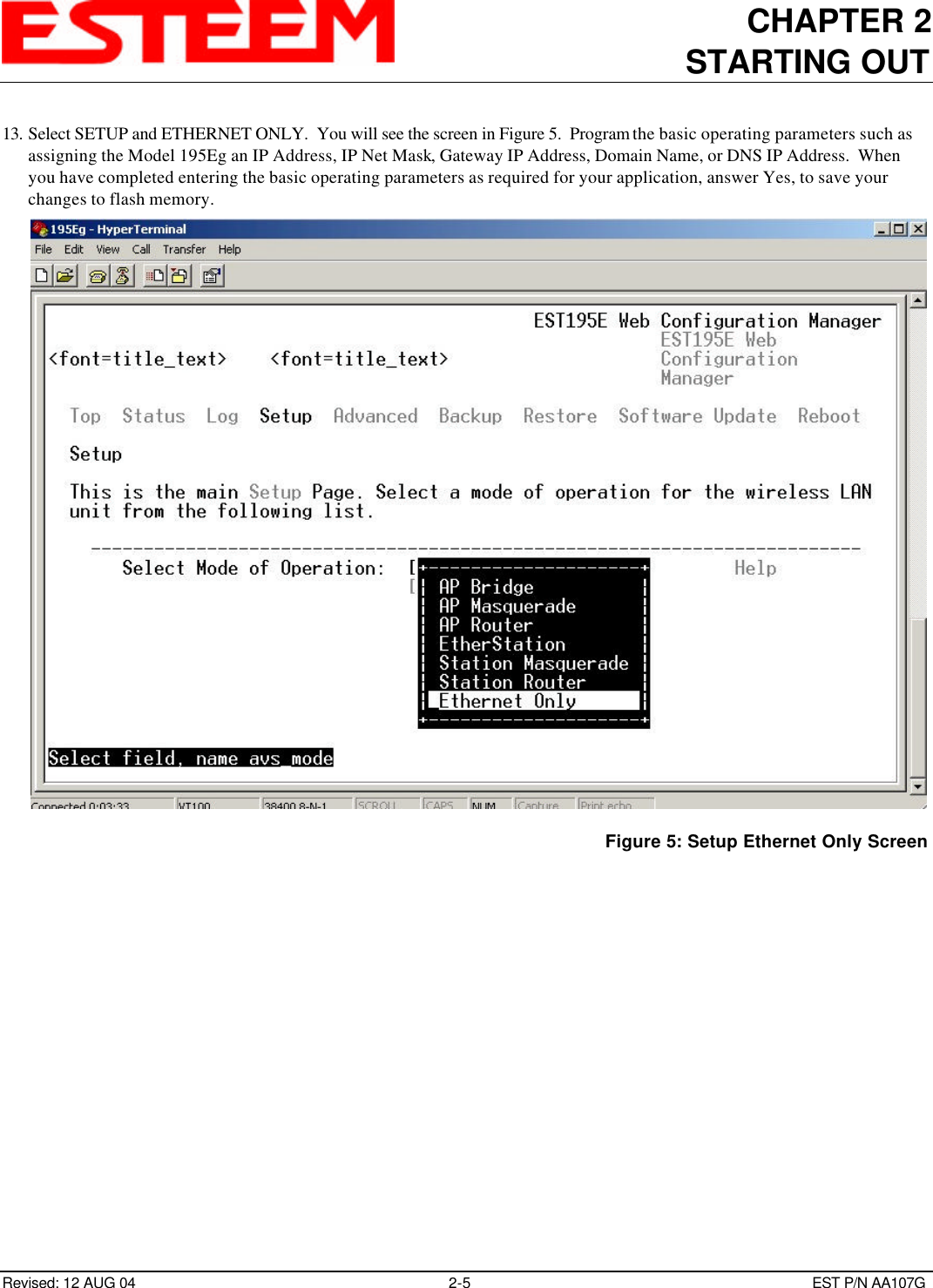
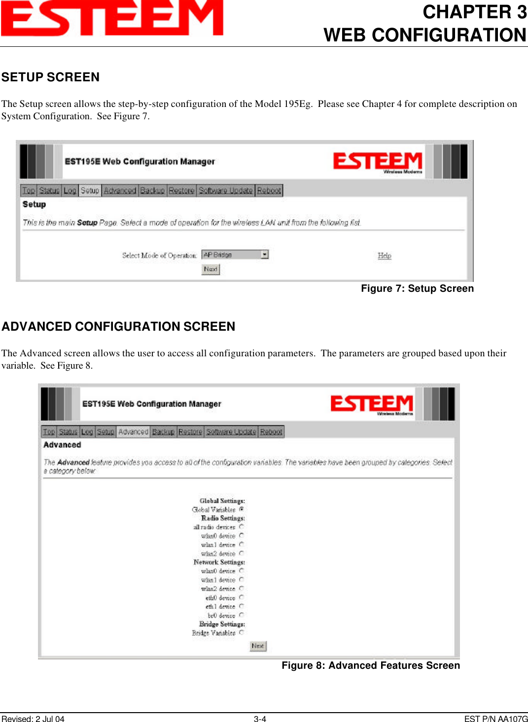
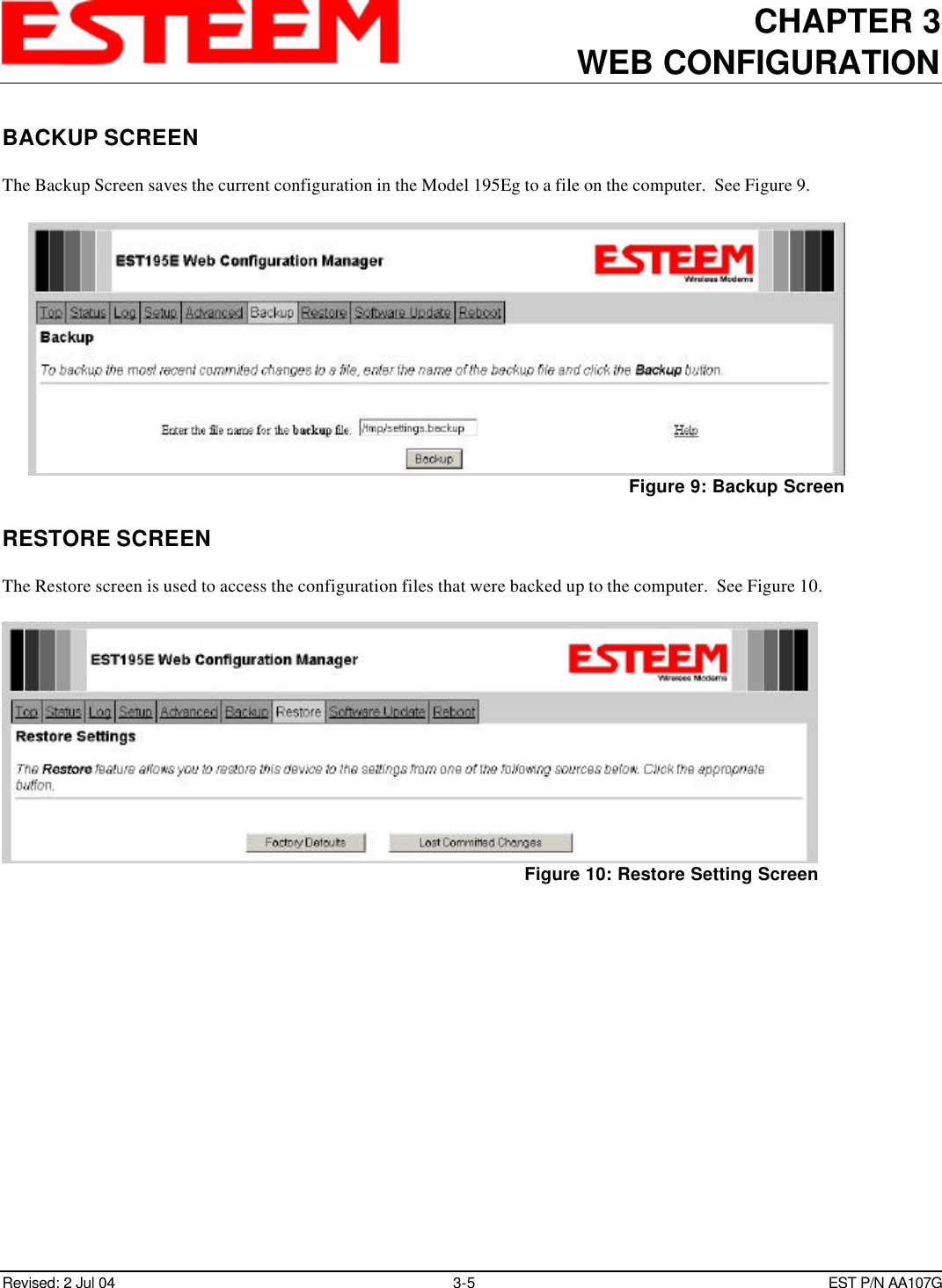
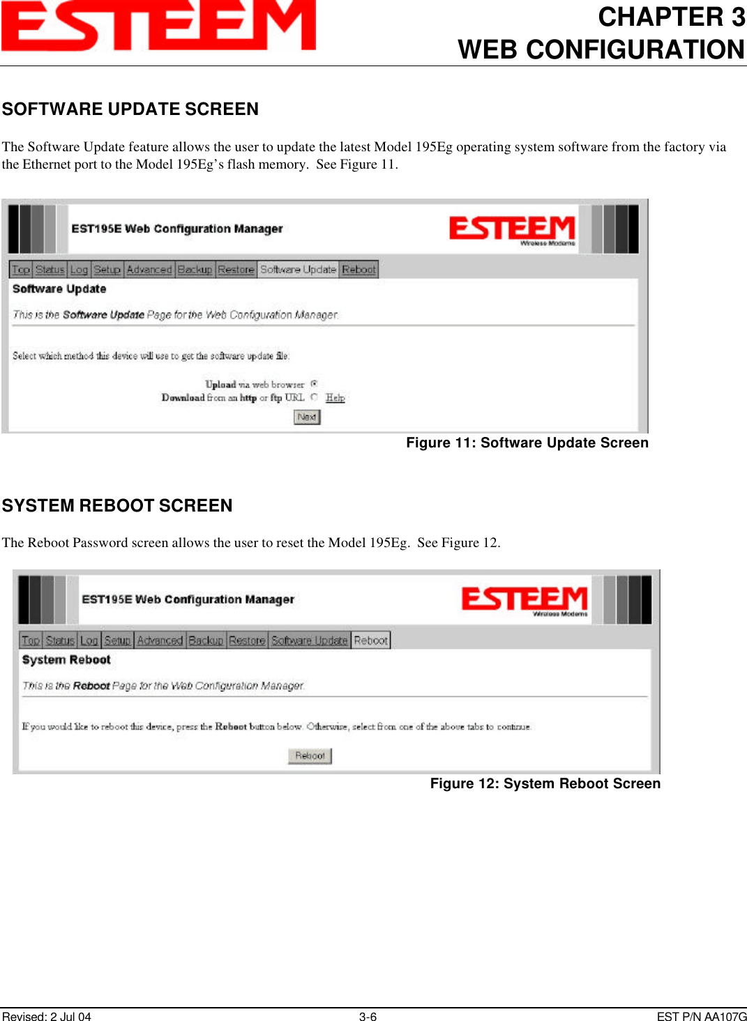
Users manual part 1 of 2

ESTeem MODEL 195EgUSER’S MANUALManual Revision 1.0June 2004Electronic Systems Technology, Inc.
ESTeem MODEL 195EgUSER’S MANUALManual Revision 1.0Firmware Version 3.3.0 and aboveJune 2004Prepared by: Date:Name: Eric P. MarskeTitle: Manager Customer SupportApproved by: Date:Name: Tom L. KirchnerTitle: President
COPYRIGHT INFORMATIONThis manual and the firmware described in it are copyrighted by EST, with all rights reserved.  Under the copyright laws, this manual or thefirmware internal to the ESTeem unit may not be copied, in whole or part, without the written consent of EST.  Under the law, copyingincludes translating into another language.Electronic Systems Technology (EST) cannot guarantee that you will receive notice of a revision to the firmware described in the manual,even if you have returned a registration/warranty card received with the product.  You should periodically check with your authorized ESTdealer or call factory direct.EST and the EST logo are registered trademarks of Electronic Systems Technology, Inc.  Simultaneously published in the United Statesand Canada.  All rights reserved.WARRANTY INFORMATIONElectronic Systems Technology, Inc., (hereinafter EST) expressly warrants its products as free of manufacturing defects for a period of oneyear from the date of sale to first user/customer. THERE ARE NO OTHER WARRANTIES, EXPRESS OR IMPLIED AND THERE IS EXPRESSLY EXCLUDED ALL WARRANTIES OFMERCHANTABILITY OR FITNESS FOR A PARTICULAR PURPOSE.  NO OTHER WARRANTY GIVEN BY ANY EMPLOYEE, AGENT,DISTRIBUTOR OR OTHER PERSON WITH RESPECT TO THE PRODUCT SHALL BE BINDING ON EST.LIMITATION OF LIABILITY: EST's liability shall be limited to refunding of purchase price, repair or replacement of product.  IN NO EVENT SHALL EST HAVE LIABILITY FOR CONSEQUENTIAL, INCIDENTAL, SPECIAL OR EXEMPLARY DAMAGESCAUSED DIRECTLY OR INDIRECTLY BY THE PRODUCT, INCLUDING BUT NOT LIMITED TO ANY INTERRUPTION OF SERVICES,LOSS OF BUSINESS OR ANTICIPATORY PROFITS.  IN NO EVENT SHALL EST BE LIABLE FOR ANY DAMAGES WHATSOEVER INEXCESS OF THE PURCHASE PRICE OF THE PRODUCT.In the event that a unit or part requires replacement or factory servicing, the following conditions apply:a) Customer must obtain from EST an authorized RMA (Return Materials Authorization) number (call 509-735-9092 Customer Support)before shipment of product or parts to EST for any reason;b) If the whole unit is shipped, it must be in its original carton and shipping components, or a carton and shipping components suppliedby EST, or if parts only are shipped, they must be packaged and cushioned so as to prevent damage in transit and shipped freightprepaid;PRODUCT WILL BE CONSIDERED OUT OF WARRANTY IF:a) If the product is damaged due to improper or abnormal use, abuse, mishandling, accident or improper maintenance or failure tofollow operating instruction;b) If the product is defective as a result of sand, dirt, or water damage;c) If any factory-sealed enclosure has been opened or shows evidence of an attempt to be opened;d) If defects or damage are caused by the use of unauthorized parts or unauthorized service;e) If the product has had its serial numbers altered or removed.Warranty repair form must be accompanied by proof of user's purchase of unit.  Product must be shipped to the manufacturer at thefollowing address:Electronic Systems Technology415 North Quay StreetKennewick, Washington USA 99336ADDITIONAL SERVICE: If EST releases an improvement update to firmware internal to the ESTeem unit during the 90 day period after the unit was purchased by thefirst user/customer, EST will update the applicable unit with the revised version at no charge other than for UPS handling and shipping to andfrom your location to the EST factory.  Return of any such item must be accompanied with proof of purchase.
TABLE OF CONTENTSRevised: 18 Jun 04 Page 1EST P/N AA107GCHAPTER 1 – INTRODUCTION    Model 195Eg Overview 1-1        Figure 1: Access Point Bridge Mode Diagram --------------------------------------------- 1-1    Model 195Eg Configuration Modes 1-1        Figure 2: Access Point Masquerade Mode Diagram --------------------------------------------- 1-1        Figure 3: Access Point Repeater Mode Diagram --------------------------------------------- 1-2CHAPTER 2 – STARTING OUT    Model 195Eg Hardware Layout 2-1        Figure 1: Model 195Eg Hardware Layout Diagram --------------------------------------------- 2-1    Model 195Eg Configuration 2-2        Figure 2: Model 195Eg Front Panel Description --------------------------------------------- 2-2        Figure 3: RS-232 Port Log-in Screen --------------------------------------------- 2-3        Figure 4: RS-232 Welcome Screen --------------------------------------------- 2-4        Figure 5: Setup Ethernet Only Screen --------------------------------------------- 2-5        Figure 6: Commit Changes Screen --------------------------------------------- 2-6CHAPTER 3 – WEB CONFIGURATION    Hardware Setup 3-1        Figure 1: Hardware Setup Using LAN Ethernet Connection --------------------------------------------- 3-1        Figure 2: Hardware Setup Direct to Computer --------------------------------------------- 3-1    Logging on to the ESTeem Web Page 3-2        Figure 3: ESTeem Web Page Log-on Screen --------------------------------------------- 3-2        Figure 4: Top Menu Screen --------------------------------------------- 3-2    Status Menu Screens 3-3        Figure 5: Status Screen --------------------------------------------- 3-3        Figure 6: System Log Screen --------------------------------------------- 3-3        Figure 7: Setup Screen --------------------------------------------- 3-4        Figure 8: Advanced Feature Screen --------------------------------------------- 3-4        Figure 9: Backup Screen --------------------------------------------- 3-5        Figure 10: Restore Setting Screen --------------------------------------------- 3-5        Figure 11: Software Update Screen --------------------------------------------- 3-6        Figure 12: System Reboot Screen --------------------------------------------- 3-6CHAPTER 4 – CONFIGURATION SETUP    Access Point Bridge with Repeater Enabled 4-1        Figure 1: Access Point Bridge Diagram --------------------------------------------- 4-1        Figure 2: Access Point Bridge Setup Screen --------------------------------------------- 4-2        Figure 3: DHCP Client Setup Screen --------------------------------------------- 4-2        Figure 4: IP Address Setup Screen --------------------------------------------- 4-3        Figure 5: DHCP Setup Screen --------------------------------------------- 4-3        Figure 6: SSID Setup Screen --------------------------------------------- 4-4
TABLE OF CONTENTSRevised: 18 Jun 04 Page 2EST P/N AA107G        Figure 7: Encryption Setup Screen --------------------------------------------- 4-4        Figure 8: Commit Changes Menu Screen --------------------------------------------- 4-5CHAPTER 5 – REPEATING FEATURES    Auto Routing 5-1        Figure 1: Conventional Access Point Diagram --------------------------------------------- 5-1    Auto-Routing Process 5-1        Figure 2: AP Repeater Diagram --------------------------------------------- 5-1    Root Bridge 5-2    Using The Access Control List (ACL) in Network Design 5-3        Figure 3: ACL Configuration Example --------------------------------------------- 5-3CHAPTER 6 – ANTENNA SETUPS    Antenna and Cable Configurations 6-1    Coaxial Cable Attenuation 6-2    Model 195Eg Series with Direct Mount Dual Diversity Antennas 6-3    Model 195Eg Series with External Mount Antenna 6-4    Fresnel Zone 6-5APPENDIX A – FCC INFORMATIONAPPENDIX B – SPECIFICATIONS
CHAPTER 1INTRODUCTIONRevised: 24 Jun 04 1-1EST P/N AA107GMODEL 195Eg OVERVIEWThe ESTeem Model 195Eg is a IEEE802.11g and IEEE 802.11b protocolcompatible wireless LAN transceiver thatcan used to build a Wireless Local AreaNetwork (WLAN) for line-of-sightdistances to 7 miles for fixed base andmobile applications.  The IEEE 802.11WLAN was designed to look and feel likeany IEEE 802 wired LAN.  The Model195Eg can be configured for multiplemodes of operation depending upon theneeds of the wireless and wired LANsystem.MODEL 195Eg CONFIGURATIONMODESThe Model 195Eg can be configured formultiple modes of operation without any changes to the hardware:1. Access Point Bridge Mode.  When the Model 195Eg is configured as an Access Point it will provide a wireless bridge froma hardwired Local Area Network (LAN) to laptops, office computers, Personal Digital Assistants (PDA’s), video cameras,PLC’s, etc. that have integral or external 802.11g or 802.11b wireless devices.  All Access Points can be physicallyconnected to the same network (LAN) or through a radio link but using the Access Point Repeater mode to provideseamless Ethernet communication for mobile devices.  The ESTeem Model 195Eg in Access Point Bridge mode will pass allnetwork traffic between connected devices including global network broadcasts.2. Access Point Router Mode.  In this mode the ESTeem Model 195Eg will function the same as the Access Point BridgeMode described above with the following exception, the Access Point Router mode will pass network traffic for connecteddevices but will not pass global networkbroadcasts.  This mode of operation shouldbe used instead of the Access Point Bridgemode when connecting the ESTeem tolarger LAN Networks.3. Access Point Masquerade Mode.  TheAccess Point Masquerade mode is aspecial use of the Access Point modewhere the Model 195Eg will connect802.11g or 802.11b wireless devices asclients into a single static IP address on anetwork.  The 195Eg will hide all the IPaddresses connected on the wireless link. You should use this mode of operation ifModel 195Eg is connected directly to theInternet with a static IP address (DSL, T1,etc.) and you want the wireless clients toaccess the information through the Model195Eg (Figure 2).  This mode should also beFigure 1: Access Point Bridge Mode DiagramFigure 2: Access Point Masquerade Mode Diagram
CHAPTER 1INTRODUCTIONRevised: 24 Jun 04 1-2EST P/N AA107Gused for attaching the Model 195Eg to anetwork where few IP addresses areavailable or a separate, inaccessiblesubnet for the wireless clients isrequired.4. Access Point Repeater Modes.  TheAccess Point Repeater is a uniqueenhancement of the 802.11g AccessPoint mode.  This feature is availableonly in the ESTeem Model 195Eg.  Withthis repeater feature enabled, the Model195Eg Access Points do not have to behardwired together on the samephysical LAN to provide seamlessEthernet communication for roaming802.11b/g Clients.  On power up theModel 195Eg will automaticallyassociate with other Model 195Egsprogrammed with the sameconfiguration (i.e. SSID, Frequency,Security, etc.) for routing message traffic over the wireless Ethernet network.  If there are multiple routes to a destination,this feature will create a “self-healing” network by automatically re-routing data through an alternate path to reach itsdestination if the primary path is inoperable.  When programmed in any of the Access Point modes, the Model 195Eg willalso bridge any Ethernet network or Ethernet device connected to the unit over this same wireless Ethernet network.  Thismode gives the user the features of a point to multi-point bridge network but also allows 802.11b/g Client devices or theModel 195Eg in the Client mode to roam under the network.  See Figure 3.5. EtherStation Mode.  This is a special feature of the Model 195Eg when used in an Access Point application.  When the195Eg is configured in the EtherStation Mode and attached to a single Ethernet Device, the Model 195Eg will emulate an802.11g PCMCIA wireless card in functionality for communication to an 802.11g Access Point.  This mode can providegreatly increased range over a Wireless LAN Card for mobile Ethernet devices such as vehicles, forklifts, cranes, etc.  SeeFigures 1 - 3.6. Station Router Mode.  This is a special feature of the Model 195Eg when used in an Access Point application wheremultiple devices will be connected to a single ESTeem in a mobile or Client application.  When the 195Eg is configured inthe Station Router Mode and attached to multiple Ethernet devices, the Model 195Eg will emulate an 802.11g client infunctionality for communication to an 802.11g Access Point.  This mode would be used where multiple Ethernet devices willbe connected to a single Model 195Eg in a mobile application and the IP addresses for each device will be visible on theLAN connected to the Access Point.  See Figure 2.7. Station (Router) Masquerade Mode.  This is a special feature of the Model 195Eg when used in an Access Point applicationwhere multiple devices will be connected to a single ESTeem in a mobile or Client application.  When the 195Eg isconfigured in the Station Router Mode and attached to multiple Ethernet devices, the Model 195Eg will emulate an 802.11gclient in functionality for communication to an 802.11g Access Point.  This mode would be used where multiple Ethernetdevices will be connected to a single Model 195Eg in a mobile application and the IP addresses for each device will behidden on the LAN connected to the Access Point.  See Figure 2.To begin setup of your wireless Ethernet network you must first configure the Model 195Eg for the mode desired.  Chapter 2 willshow you how to begin programming the Model 195Eg.Figure 3: Access Point Repeater Mode Diagram
CHAPTER 2STARTING OUTRevised: 12 AUG 04 2-1EST P/N AA107GChapter 2 of the User’s Manual will show basic configuration of the system using the RS-232 port to allow further programmingusing the ESTeem Web Page shown in Chapter 3.When powering up the ESTeem for the first time you must use the ESTeem RS-232C Configuration Menu to setup the basicoperating parameters such as assigning the ESTeem an IP Address, IP Net Mask, Gateway IP Address, Domain Name, andDNS IP Address.  Once the IP address is configured you can communicate to the ESTeem through your web browser.Any terminal emulation program can be used for this configuration of the ESTeem.  Most Windows users will probably useHyper Terminal.  Configure your RS-232C port for a Baud Rate to 38,400, Data Bits to 8, Parity to None, Stop Bits to 1 andHandshaking to None. Once your ESTeem has an IP address, you can attach the ESTeem to your network and use the WebServer for further programming.MODEL 195Eg HARDWARE LAYOUTLocate the items contained in Figure 1 for initial configuration of the ESTeem Model 195Eg. Take a few minutes to inventoryyour equipment before you proceed. Report any missing or damaged items to Customer Support (509-735-9092) as soon aspossible.  Notes:• There is no Power On/Off switch on the Model 195Eg.• Attach the programming Cable to the RS-232 Programming Port and the Patch Cable between the Power Supply andEthernet port.• One word of caution please attached an antenna to the Model 195Eg before power up.Figure 1:  Model 195Eg Hardware Layout Diagram
CHAPTER 2STARTING OUTRevised: 12 AUG 04 2-2EST P/N AA107GMODEL 195Eg CONFIGURATIONThe following steps should be completed before any modifications are made to the network operating parameters for theESTeem Model 195Eg.1. Connect the antenna to the antenna connector on the ESTeem Model 195Eg (Figure 2).2. When powering up the Model 195Eg for the first time you must use the ESTeem RS-232CConfiguration Menu to setup the basic operating parameters such as assigning the IPAddress, IP Net Mask, Gateway IP Address, Domain Name, and DNS IP Address.  3. Connect the serial cable (EST P/N: AA0621) between the RS-232 connector on the Model 195Eg to the serial port on thecomputer.4. Any terminal emulation program can be used for the configuration of the Model 195Eg.  Most Windows users use HyperTerminal.  Configure your RS-232C port for a Baud Rate to 38,400, Data Bits to 8, Parity to None, Stop Bits to 1 andHandshaking to None and Terminal to VT100 emulation.5. Plug the Model AA175 power supply into a wall socket and connect the Ethernet patch cable to the Model 195Eg Ethernetport.  The Power over Ethernet (POE) LED on the front of the ESTeem should be illuminated. 6. If your computer is configured properly, you will see the ESTeem Model 195Eg booting sequence on your TerminalEmulation program.Once the ESTeem boot sequence is complete (approximately 1 minute) you will receive this message: “Please press Enter to active this console.”If you don’t see this message press the Reset button on the front panel of the Model 195Eg and/or check the programmingof your RS-232 port.Figure 2: Model 195Eg Front Panel DescriptionNotes:• Configure the Model195Eg prior tomounting. • Some of the followingsteps, such asconnecting the serialcable, are easier toperform if theESTeem is accessible.• Please attach anantenna to the Model195Eg before powerup.• There is no PowerOn/Off switch on theModel 195Eg.
CHAPTER 2STARTING OUTRevised: 12 AUG 04 2-3EST P/N AA107G7. Press the Enter key and you will be at the Configuration Menu login prompt 195Eg login.  See Figure 3.8. To enter the Model 195Eg Main Menu you will need to log into the system with a login name and password.9. If this is not the first time configuration of the Model 195Eg, see your network systems administrator for the password.10. At the 195Eg login prompt type admin for the login name and press the Enter key (<Enter>).  The login name is defined atthe factory and is not changeable by the user.  Note that all characters are lower case.11. If this is the first time the Model 195Eg has been programmed or the Password was not changed from the factory defaultvalues, the factory default password is also admin.  Enter admin for the password and press the Enter key (<Enter>). Note:  All characters are lower case.Figure 3: RS-232 Port Log-in Screen
CHAPTER 2STARTING OUTRevised: 12 AUG 04 2-4EST P/N AA107G12. The ESTeem Configuration Welcome Screen (Figure 4) will now be displayed. Note:  The configuration menu will function the same as the Web Configuration Manager, but requires moving thearrows to change fields.Figure 4: RS-232 Welcome Screen
CHAPTER 2STARTING OUTRevised: 12 AUG 04 2-5EST P/N AA107G13. Select SETUP and ETHERNET ONLY.  You will see the screen in Figure 5.  Program the basic operating parameters such asassigning the Model 195Eg an IP Address, IP Net Mask, Gateway IP Address, Domain Name, or DNS IP Address.  Whenyou have completed entering the basic operating parameters as required for your application, answer Yes, to save yourchanges to flash memory.Figure 5: Setup Ethernet Only Screen
CHAPTER 2STARTING OUTRevised: 12 AUG 04 2-6EST P/N AA107G14. After the basic parameters have been entered into the Model 195Eg you will need to commit the commands to the Model195Eg (Figure 6).  The changes will be saved to flash memory.   You can use the higher level programming features in theESTeem Web Configuration Manager to configure the unit for your application.  Proceed to Chapter 3. Figure 6: Commit Changes Screen
CHAPTER 3WEB CONFIGURATIONRevised: 2 Jul 04 3-1EST P/N AA107GWhen powering up the Model 195Eg forthe first time you must use the ESTeemRS-232C Configuration Menu to setup thebasic operating parameters such asassigning the Model 195Eg an IP Address,IP Net Mask, Gateway IP Address, DomainName, and DNS IP Address.  This isnecessary to communicate with the Model195Eg using your web browser.  Chapter 2,Starting Out will provide detailedinformation on how this is done. HARDWARE SETUPFigure 1 shows a typical hardwareconfiguration if you are accessing theESTeem Web page from a computer over ahardwired LAN.  The Model 195Eg isinterfaced to the LAN from a Hub orSwitch.  Figure 2 shows a typical hardwareconfiguration if you are accessing theESTeem Web page from a computer interfaced directly to the Model 195Eg Ethernet port.1. Connect the antenna/s to the antenna connector on the Model 195Eg.2. Plug the Model AA175 powersupply into a wall socket andconnect the Ethernet patchcable to the Ethernet port onthe Model 195Eg.  The Powerover Ethernet (POE) LED onthe front of the Model 195Egshould be illuminated. 3. Connect the Ethernet cable tothe LAN or computer.Notes:• There is no Power On/Offswitch on the Model 195Eg.• Please attach an antenna tothe Model 195Eg beforepower up.• When powering up theModel 195Eg for the firsttime you must use theESTeem RS-232CConfiguration Menudescribed in Section 2 tosetup the basic operatingparameters such as assigning the IP Address, IP Net Mask, Gateway IP Address, Domain Name, and DNS IP Address.Figure 1: Hardware Setup Using LAN Ethernet ConnectionFigure 2: Hardware Setup Direct to Computer
CHAPTER 3WEB CONFIGURATIONRevised: 2 Jul 04 3-2EST P/N AA107GLOGGING ON TO THE ESTeem WEB PAGE1. Using your Web Browser connect to the Model 195EgWeb Page with the IP Address that you have assigned itin Chapter 2.2. You will now see the Log-on Menu on Figure 3. To enterthe Model 195Eg Status Menu you will need to log intothe system with a User Name and Password. 3. For the User Name enter admin and press the Enter key(<Enter>).   The User Name is defined at the factory and isnot changeable.4. Enter your Password and press the Enter key (<Enter>).If this is the first time the Model 195Eg has beenprogrammed and Password was not changed from thefactory default values, proceed with the steps below to access the Configuration Menu.• The factory default Password is also admin.  Enter admin for the Password and press the Enter key (<Enter>).• Note: All characters are lower case.5. After Log-in the next screen displayed will be the Model 195Eg Top Menu page (Figure 4).  This example screen shows theTop Menu screen.Note: Throughout the Configuration Manager are Help Screens that can accessed for further information on each item.Figure 3: ESTeem Web Page Log-on ScreenFigure 4: Top Menu Screen
CHAPTER 3WEB CONFIGURATIONRevised: 2 Jul 04 3-3EST P/N AA107GSTATUS MENU SCREENSThe ESTeem Web Page Status Menu displays the current mode of operation and status of the communication links to otherwireless devices. The Status Menu lists connected wireless devices (either other Model 195Egs or 802.11g clients), their signalstrength, data rate and background noise.  An example is shown below in Figure 5:SYSTEM LOG SCREENThe Log Screen is a trouble-shooting tool that shows the current log of Model 195Eg system messages.  See Figure 6.Figure 5: Status ScreenFigure 6: System Log Screen
CHAPTER 3WEB CONFIGURATIONRevised: 2 Jul 04 3-4EST P/N AA107GSETUP SCREENThe Setup screen allows the step-by-step configuration of the Model 195Eg.  Please see Chapter 4 for complete description onSystem Configuration.  See Figure 7.ADVANCED CONFIGURATION SCREENThe Advanced screen allows the user to access all configuration parameters.  The parameters are grouped based upon theirvariable.  See Figure 8.Figure 7: Setup ScreenFigure 8: Advanced Features Screen
CHAPTER 3WEB CONFIGURATIONRevised: 2 Jul 04 3-5EST P/N AA107GBACKUP SCREENThe Backup Screen saves the current configuration in the Model 195Eg to a file on the computer.  See Figure 9.RESTORE SCREENThe Restore screen is used to access the configuration files that were backed up to the computer.  See Figure 10.Figure 9: Backup ScreenFigure 10: Restore Setting Screen
CHAPTER 3WEB CONFIGURATIONRevised: 2 Jul 04 3-6EST P/N AA107GSOFTWARE UPDATE SCREENThe Software Update feature allows the user to update the latest Model 195Eg operating system software from the factory viathe Ethernet port to the Model 195Eg’s flash memory.  See Figure 11.SYSTEM REBOOT SCREENThe Reboot Password screen allows the user to reset the Model 195Eg.  See Figure 12.Figure 11: Software Update ScreenFigure 12: System Reboot Screen

Navigation menu