Electronic Systems Technology ESTEEM195EP BASE STATION TRANSMITTER User Manual CHAPTER 2
Electronic Systems Technology BASE STATION TRANSMITTER CHAPTER 2
Contents
- 1. FCC INFORMATION
- 2. SPECIFICATIONS
- 3. INTERFACE PORTS
- 4. RADIO CONFIGURATION
- 5. SECURITY
- 6. TROUBLESHOOTING
- 7. QUICK START GUIDE 1
- 8. FRONT COVER
- 9. TABLE OF CONTENTS
- 10. INTRODUCTION
- 11. CONFIGURATION DIAGRAMS
- 12. STARTING OUT
- 13. WEB CONFIGURATION MANAGER
- 14. EXAMPLE CONFIGURATIONS 1
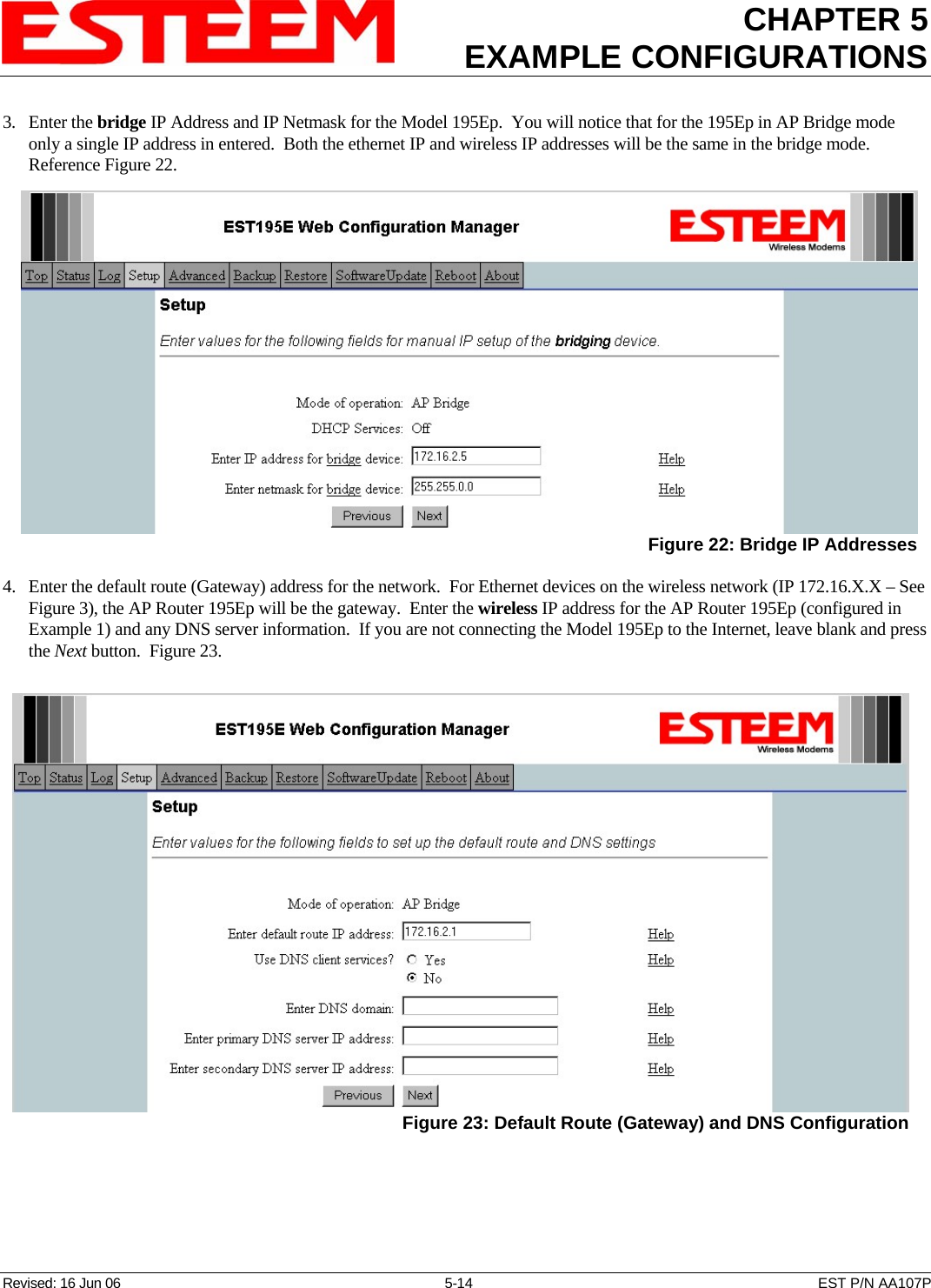
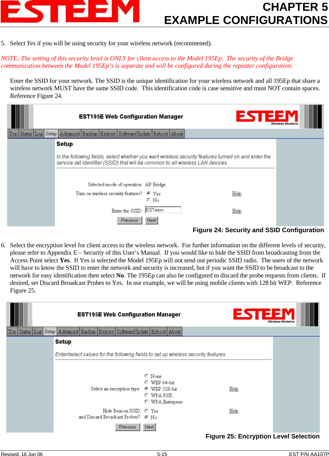
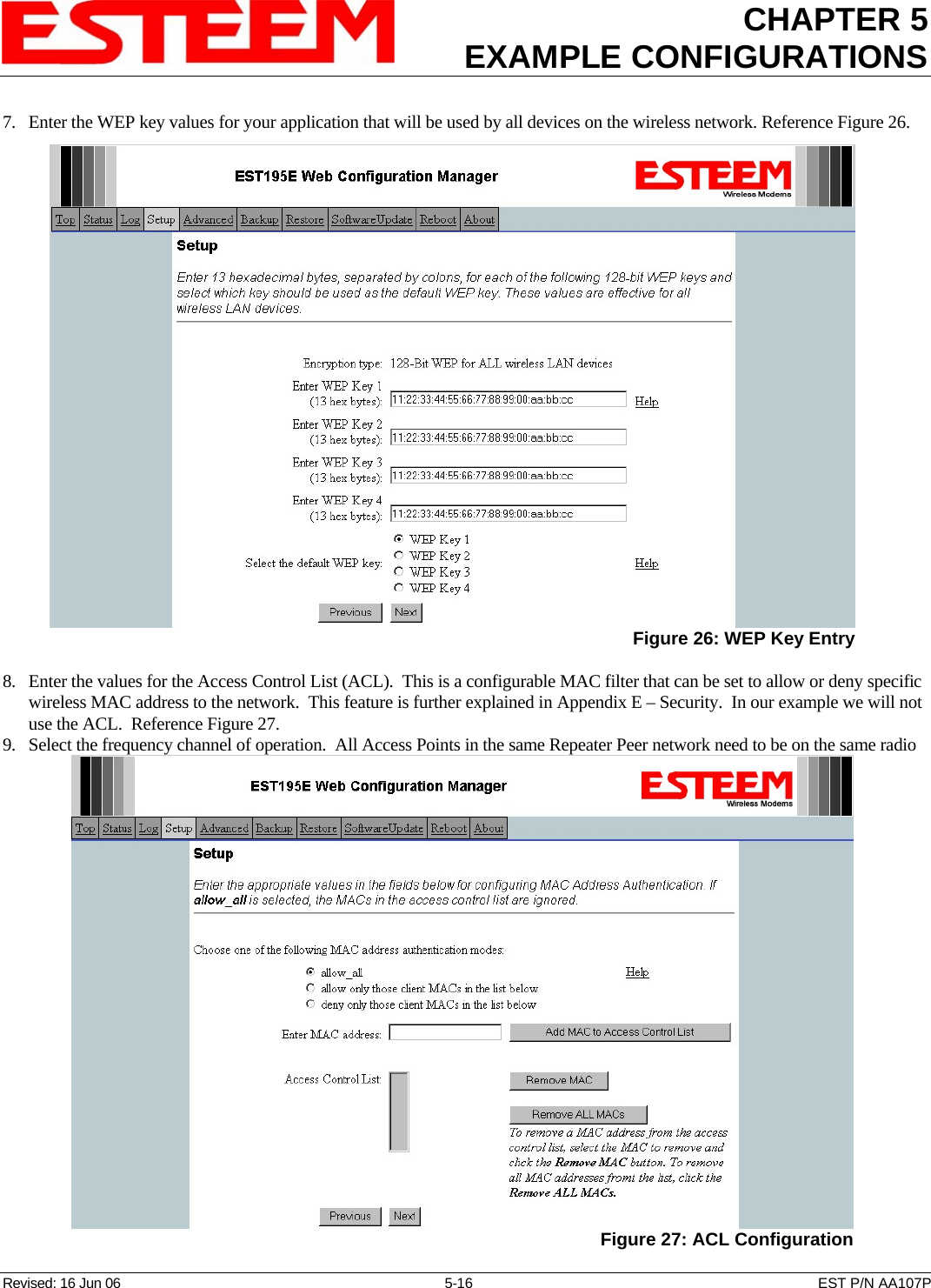
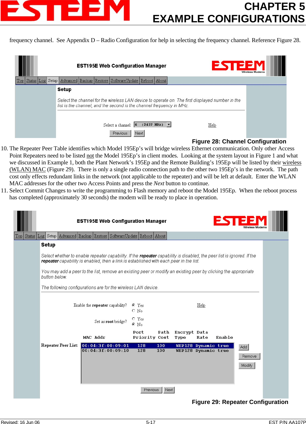
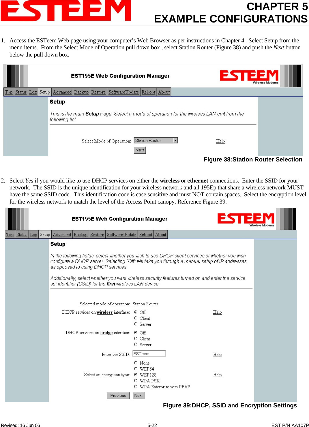
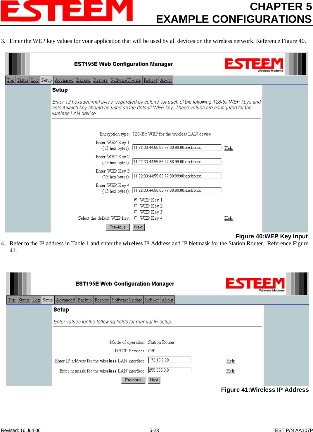
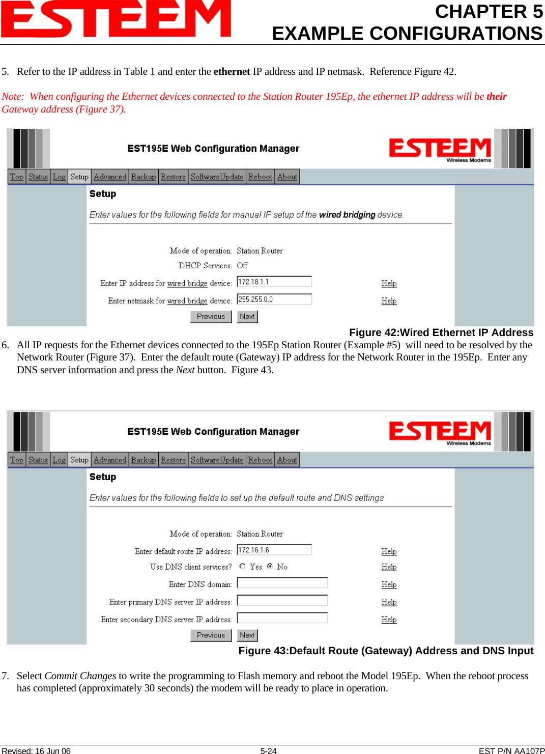
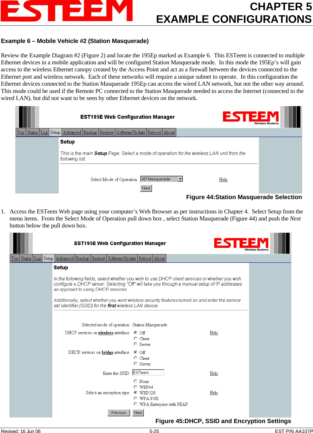
- 15. EXAMPLE CONFIGURATIONS 2
- 16. REPEATING FIGURES
- 17. ANTENNA SETUP
- 18. QUICK START GUIDE 2
- 19. QUICK START GUIDE 3
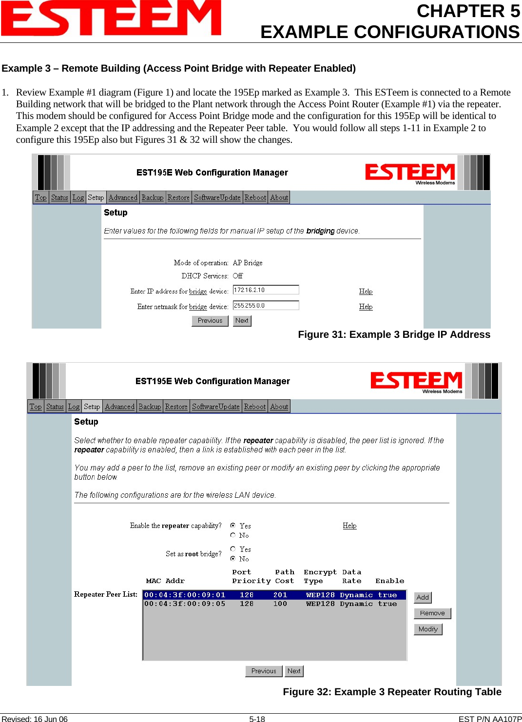
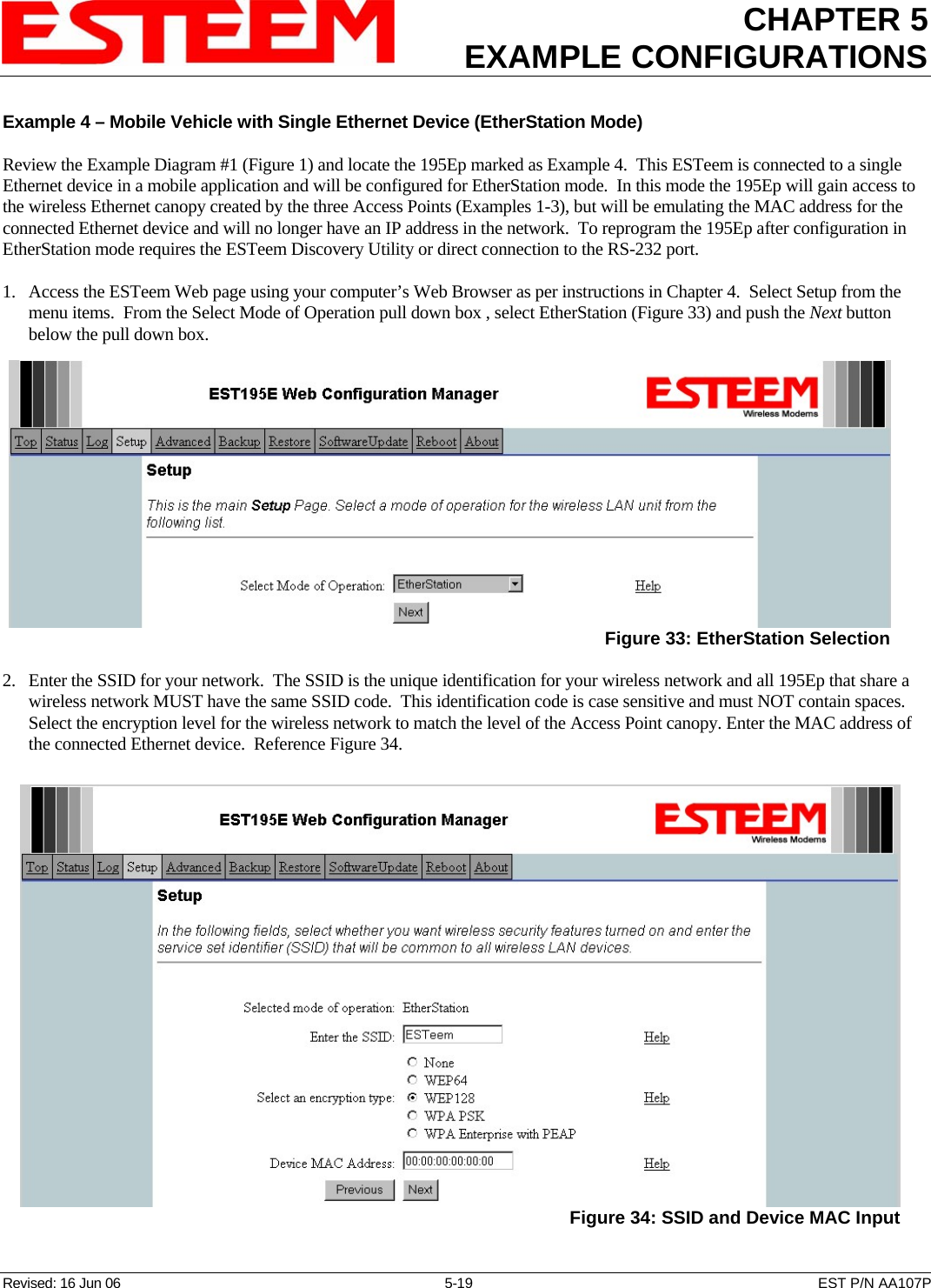
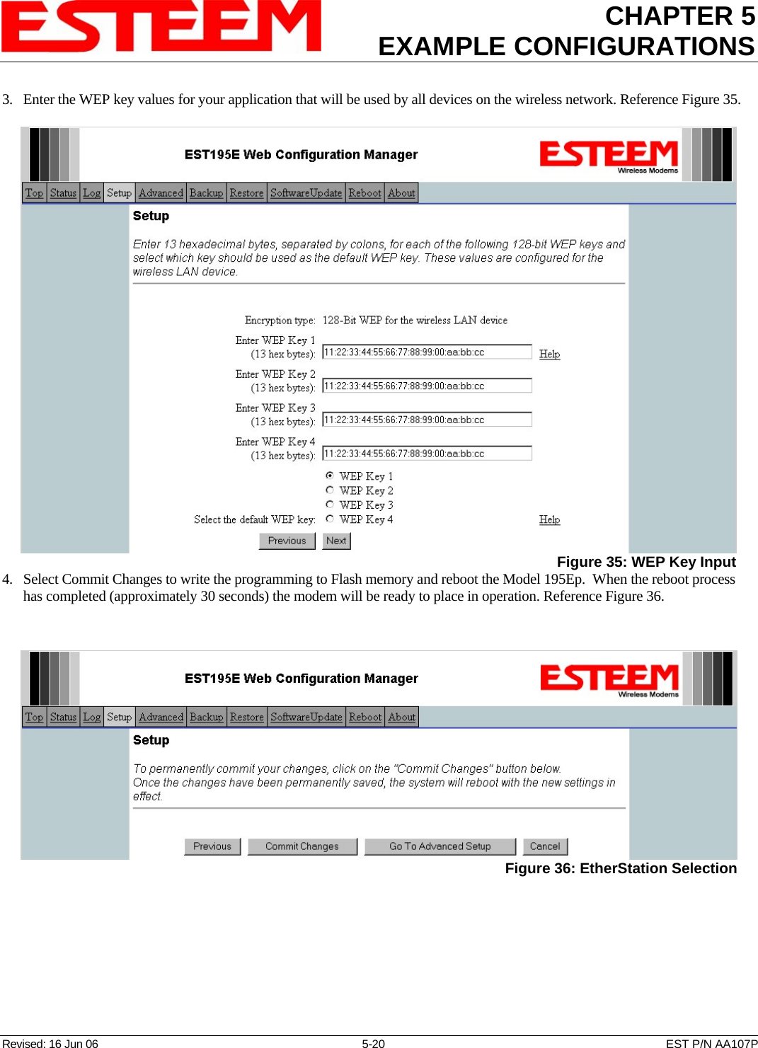
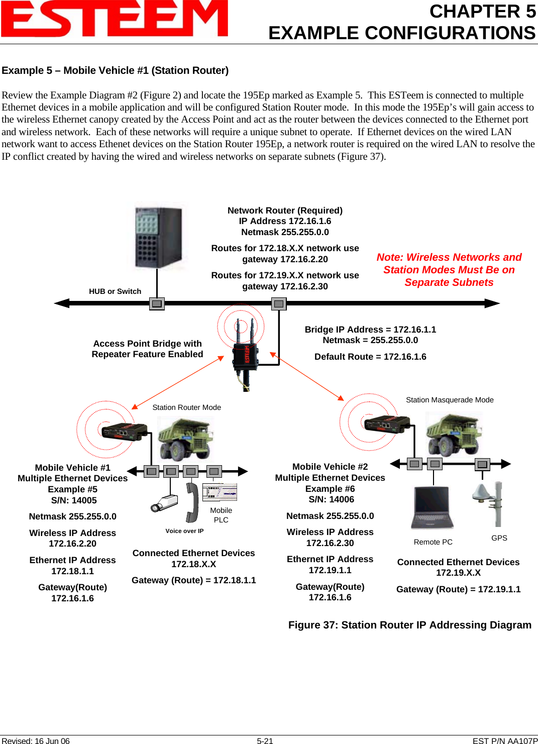
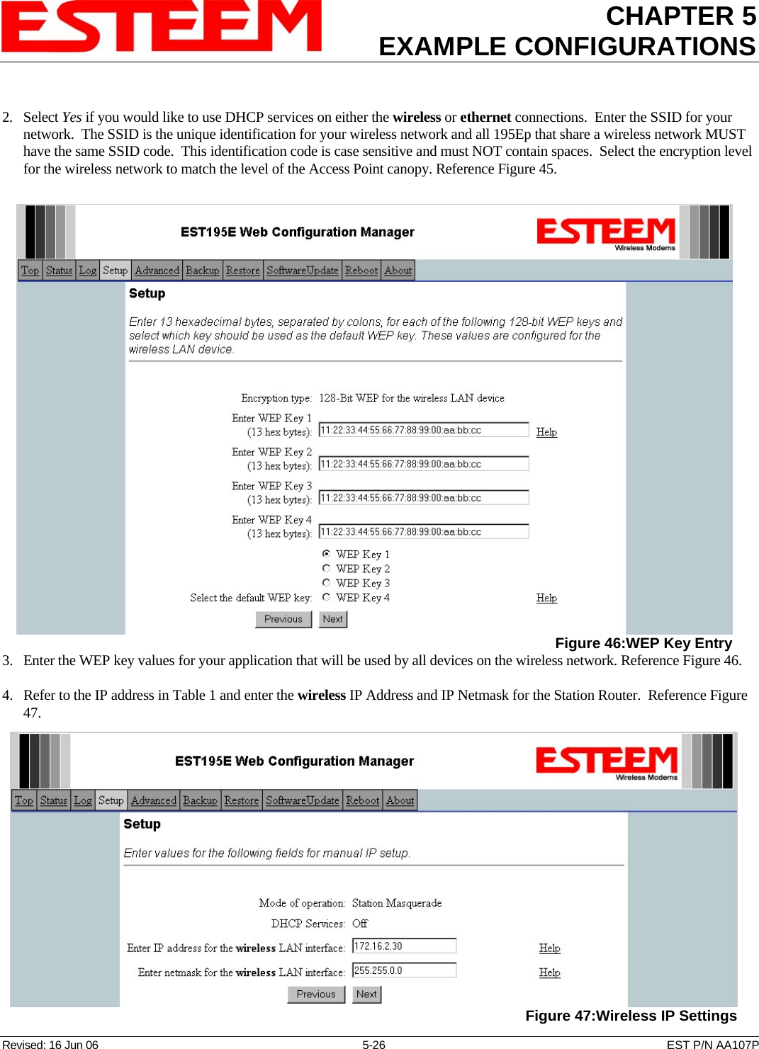
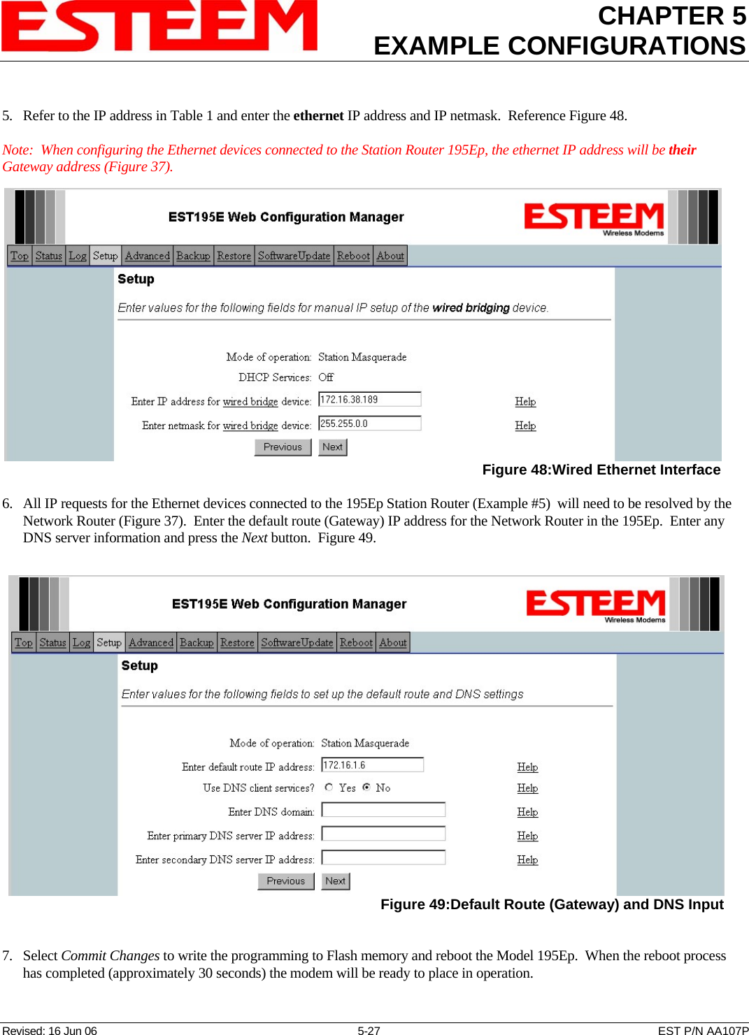
EXAMPLE CONFIGURATIONS 2