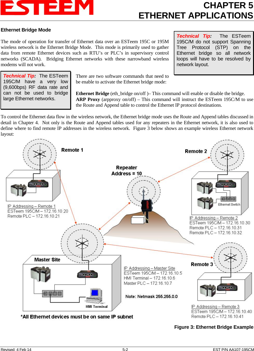
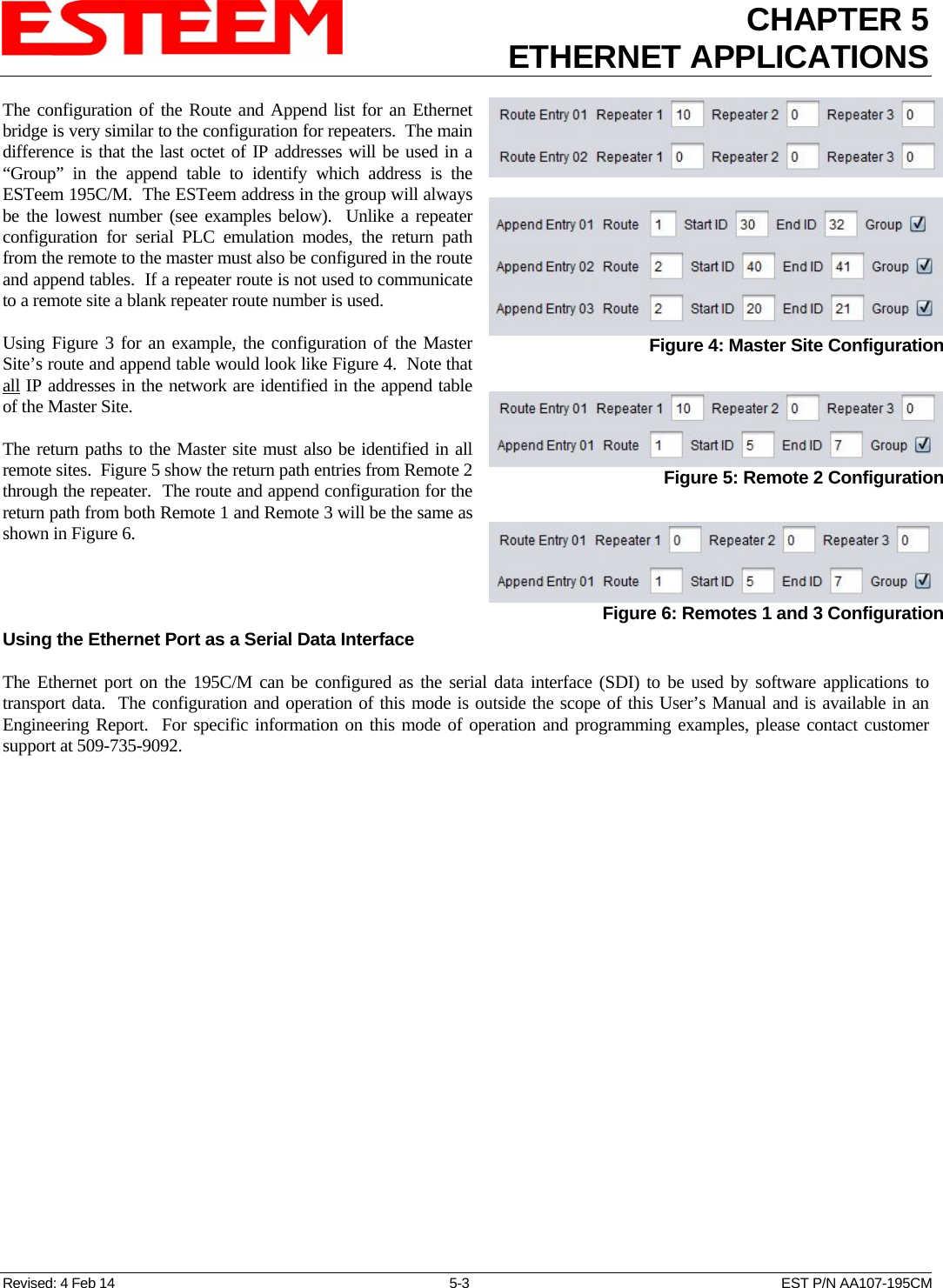
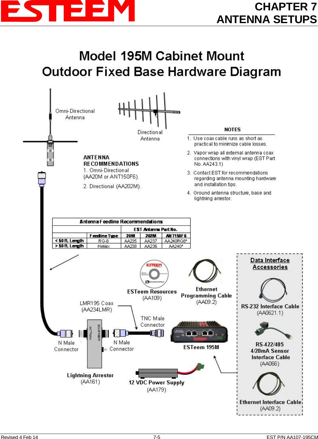
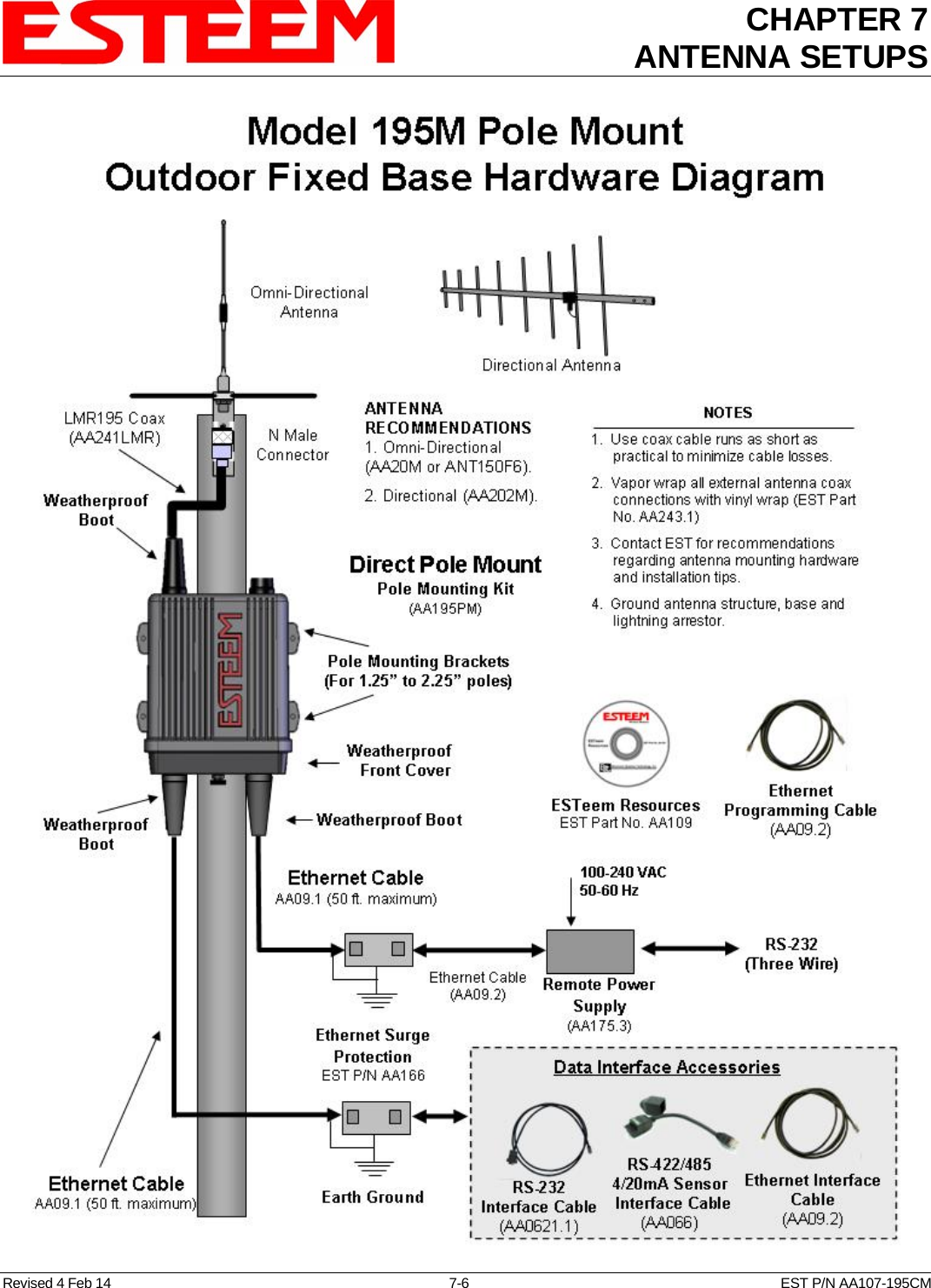
Electronic Systems Technology ESTEEM195H 217-220MHz VHF Telemetry Modem User Manual

Electronic Systems Technology 217-220MHz VHF Telemetry Modem

User Manual

                ESTeem USER’S MANUAL  Models 195C – 195M   Manual Revision 1.0 February 2014      Electronic Systems Technology, Inc.
                  Author:   Date:Name:  Eric  P. Marske Title:  Product Support Manager   Approved by:   Date:Name:  Tom L. Kirchner Title:  President   Electronic Systems Technology, Inc. Building B1 415 N. Quay Street Kennewick, WA 99336 Phone: 509-783-9092 Fax: 509-783-5472 E-mail: market@esteem.com Web Site: www.esteem.com   Copyright© 2014 by Electronic Systems Technology, Inc.    All rights reserved. Printed in the United States of America.  No part of this publication may be reproduced, stored in a retrieval system, or transmitted, in any form or by any means, electronic, mechanical, photocopying, recording, or otherwise, without the prior written permission of Electronic Systems Technology.
 PRODUCT WARRANTY         ELECTRONIC SYSTEMS TECHNOLOGY, INC. Specifications subject to change without notice   415 North Quay Street  Kennewick, WA  99336   www.esteem.com     Phone (509) 735-9092  Fax (509) 783-5475                                                    Revised: 4 Feb 14  Electronic Systems Technology, Inc., (hereinafter EST) expressly warrants its products as free of manufacturing defects for a period of one year from the date of sale to first user/customer.  THERE ARE NO OTHER WARRANTIES, EXPRESS OR IMPLIED AND THERE IS EXPRESSLY EXCLUDED ALL WARRANTIES OF MERCHANTABILITY OR FITNESS FOR A PARTICULAR PURPOSE.  NO OTHER WARRANTY GIVEN BY ANY EMPLOYEE, AGENT, DISTRIBUTOR OR OTHER PERSON WITH RESPECT TO THE PRODUCT SHALL BE BINDING ON EST.  LIMITATION OF LIABILITY:   EST's liability shall be limited to refunding of purchase price, repair or replacement of product.  IN NO EVENT SHALL EST HAVE LIABILITY FOR CONSEQUENTIAL, INCIDENTAL, SPECIAL OR EXEMPLARY DAMAGES CAUSED DIRECTLY OR INDIRECTLY BY THE PRODUCT, INCLUDING BUT NOT LIMITED TO ANY INTERRUPTION OF SERVICES, LOSS OF BUSINESS OR ANTICIPATORY PROFITS.  IN NO EVENT SHALL EST BE LIABLE FOR ANY DAMAGES WHATSOEVER IN EXCESS OF THE PURCHASE PRICE OF THE PRODUCT.  In the event that a unit or part requires replacement or factory servicing, the following conditions apply:  a)  Customer must obtain from EST an authorized RMA (Return Materials Authorization) Number before shipment of product or parts to EST for any reason;  b)  If the whole unit is shipped, it must be in its original carton and shipping components, or a carton and shipping components supplied by EST, or it parts only are shipped, they must be packaged and cushioned so as to prevent damage in transit and shipped freight prepaid;  PRODUCT WILL BE CONSIDERED OUT OF WARRANTY IF:  a)  If the product is damaged due to improper or abnormal use, abuse, mishandling, accident or improper maintenance or failure to follow operating instruction;  b)  If the product is defective as a result of sand, dirt, or water damage;  c)  If any factory-sealed enclosure has been opened or shows evidence of an attempt to be opened;  d)  If defects or damage are caused by the use of unauthorized parts or unauthorized service;  e)  If the product has had its serial numbers altered or removed.   Warranty repair form must be accompanied by proof of user's purchase of unit.  Product must be shipped to the manufacturer at the following address:      Electronic Systems Technology     415 North Quay Street      Kennewick, Washington USA 99336  ADDITIONAL SERVICE: If EST releases an improvement update to firmware internal to the ESTeem unit during the 90 day period after the unit was purchased by the first user/customer, EST will update the applicable unit with the revised version at no charge other than for UPS handling and shipping to and from your location to the EST factory.  Return of any such item must be accompanied with proof of purchase.
TABLE OF CONTENTS    Revised: 4 Feb 14  Page 1  EST P/N AA107-195CM CHAPTER 1 – Introduction      Before You Begin   1-1      Model 195C/M Overview   1-1         Serial Applications --------------------------------------------- 1-1         Ethernet Applications --------------------------------------------- 1-2         Sensor Applications --------------------------------------------- 1-2         Legacy Model 192 Applications --------------------------------------------- 1-2    CHAPTER 2 – Starting Out          Three Configuration Phases   2-1        Model 195Eg Hardware Configuration   2-2    CHAPTER 3 – Example Applications          Modes of Operation Description and Examples   3-1         Transparent Point to Point  --------------------------------------------- 3-1         Transparent Multipoint --------------------------------------------- 3-3         PLC Emulations --------------------------------------------- 3-4        Programming Examples   3-5         Using Model 195C/M Configuration Utility  --------------------------------------------- 3-5         Example 1 – Transparent Point to Point  --------------------------------------------- 3-6         Example 2 – Transparent Point to Point with Repeater --------------------------------------------- 3-8         Example 3 – Transparent Multipoint --------------------------------------------- 3-9         Example 4 – PLC Emulation Mode  --------------------------------------------- 3-10         Example 5 – Mobile Client Mode  --------------------------------------------- 3-15       PLC Emulation Command Lists   3-11   CHAPTER 4 – Repeating Features             Configuring Route and Append Tables ---------------------------------------------  4-1         Reading Route and Append Tables --------------------------------------------- 4-3         Clearing Route and Append Tables --------------------------------------------- 4-3    CHAPTER 5 – Ethernet Applications              Programming Through Ethernet Port ---------------------------------------------  5-1         Ethernet Bridge Mode --------------------------------------------- 5-2         Using Ethernet as Serial Device Interface (SDI)  ---------------------------------------------  5-3
TABLE OF CONTENTS    Revised: 4 Feb 14  Page 2  EST P/N AA107-195CM  CHAPTER 6 – Utilities and Features         Model 195C/M Configuration Utility   6-1         Installation --------------------------------------------- 6-1         Read Modem Configuration --------------------------------------------- 6-3         Write Modem Configuration --------------------------------------------- 6-3         Reset Modem  ---------------------------------------------  6-3         Factory Defaults  ---------------------------------------------  6-3        Modbus Monitoring   6-4         Reading Receive Signal Strength (RSSI)  ---------------------------------------------  6-4         ModbusTCP Tables  ---------------------------------------------  6-4        Save and Load Configuration File   6-5     Update Firmware   6-6     Programming Console   6-6     Diagnostics   6-6    CHAPTER 7 – Antenna Setup          Coax Cables   7-1         Weatherproofing --------------------------------------------- 7-2         Grounding  ---------------------------------------------  7-2         SWR Testing  ---------------------------------------------  7-2        Example Antenna Configurations   7-3         Model 195C Cabinet Mount --------------------------------------------- 7-3         Model 195C Pole Mount --------------------------------------------- 7-4         Model 195M Cabinet Mount --------------------------------------------- 7-5         Model 195M Pole Mount --------------------------------------------- 7-6    APPENDIX A – Software Commands       APPENDIX B – Interface Ports            Model 195C/M Front Panel Diagram --------------------------------------------- B-1         Ethernet Port --------------------------------------------- B-2         RS-232 Ports  ---------------------------------------------  B-2         RS-485 and RS-422 Ports --------------------------------------------- B-3         4/20mA Sensors --------------------------------------------- B-3    APPENDIX C – Model 192 Integration       APPENDIX D – FCC/DOC Information       APPENDIX E – 195C Specifications       APPENDIX F – 195M Specifications
CHAPTER 1 INTRODUCTION  Before You Begin  Thank you and congratulations on your purchase of the ESTeem Model 195C or 195M Wireless Radio Modem!  This manual was written to help both the first time and advanced user of the 195C/M to configure the wireless modem for your application.  If this is your first time configuring the 195C/M and you would like to get going as soon as possible, we recommend using the ESTeem Resource CD provided with the modem.  The Resource CD will provide the software utilities and guide you through the configuration of the wireless modem for your application. Revised: 4 Feb 14  1-1  EST P/N AA107-195CM  The ESTeem 195C/M wireless modems are programmed through their Ethernet interface.  To keep the manual usably short, many of the application descriptions and programming details assume the user has a good working knowledge of the following network concepts:  Figure 1: ESTeem Model 195C/M Series    General Ethernet networking and the configuration of LAN topologies   Common Ethernet terminology and acronyms  TCP/IP network protocol structure and how to configure TCP/IP networks and subnets Throughout this User’s Manual are “Technical Tips” in boxes like this that have been added to help answer the most commonly asked questions.  How to identify and set the TCP/IP address on your computer  Have administrator privileges to the computer and network you are configuring  If using routing protocols, you must be able to identify and configure the network routers, gateways and firewalls  You must be familiar with using web browser software such as Internet Explorer, Chrome or Firefox  If you are unfamiliar with any of the above networking concepts, you may need to contact your network administrator for assistance.   Model 195C/M Overview  The ESTeem Model 195C and 195M are wireless modem transceivers that can be used to build many types of Wireless Local Area Networks (WLAN).  The ESTeem 195C/M series have multiple serial (RS-232, RS-422 and RS-485), Ethernet and 4/20mA sensor interfaces.  The Model 195C and 195M can be configured for multiple modes of operation depending upon the needs of the wireless and wired network.  The following interface configurations are provided as an overview of the basic network types, as all possible network configurations can not be listed.  For further help in selecting the correct network type, please refer to Chapter 3 of this User’s Manual or call Customer Support at 509-735-9092.    Serial Applications  A Model 195C/M can be configured for point-to-point, multipoint or PLC emulations without any changes to the hardware.  The following are brief descriptions of the Serial Device Interface (SDI) configuration modes.  For detailed descriptions and suggested applications for each mode, please refer to Chapter 3.   RS-232 – The ESTeem 195C and 195M have two (2) RS-232 data ports.  One RS-232 port (Port 4) is available for use when the ESTeem 195C/M is remote pole mounted (Figure 2), but only supports the basic three wire (Transmit, Receive and Ground) connection without any handshaking.  The second RS-232 port (Port 3) has full  Figure 2 – Pole Mount Configuration
CHAPTER 1 INTRODUCTION  Revised: 4 Feb 14  1-2  EST P/N AA107-195CM hardware handshaking through the request to send (RTS) and clear to send (CTS) lines.  Both ports are software configurable from 2,400 to 115,000 bps.  RS-422 – The ESTeem 195C and 195M have a single RS-422 data port (Port 2).  The RS-422 data port is shared on the front panel with the 10/100 Mbps Ethernet interface.  The RS-422 interface is good for long distances to 4,000 feet at bauds rate software configurable from 2,400 to 115,000 bps.  RS-485 – The ESTeems have a single, two-wire RS-485 data port (Port 1).  The RS-485 data port is shared on the front panel with the 4/20mA sensors.  The RS-485 interface is good for long distances to 4,000 feet at baud rates software configurable from 2,400 to 115,000 bps.   Ethernet Applications   The ESTeem 195C and 195M have a 10/100 Mbps Ethernet interface (Port 2) that is used as both a data port and the primary programming port.  When the Ethernet port is used as a data port there are two modes of operation.  The primary use will be as a slow speed (9,600 bps) Ethernet bridge to remote locations to gather data from remote Ethernet devices.  The secondary mode of operation is to configure the Ethernet port as a TCP or UDP Socket and write custom software applications to access the data port.  Each of these modes of operation are described in detail in Chapter 5.    Sensor Applications   The ESTeem 195C and 195M have four (4) independent configurable 4/20mA sensor inputs.  The sensor inputs can be read from the 195C/M though either their ModbusTCP address or through a serial software command.  These values can be read either locally our through the wireless network.   Legacy - Model 192 Applications  The ESTeem 195C can be integrated with our legacy ESTeem Model 192C or Model 192CHP, while the 195M can be integrated with Models 192M or 192MHP networks.  There is a specific procedure to follow when integrating the new 195C or 195M in an existing network that can be found in Appendix C of this User’s Manual.   To begin setup of your wireless Ethernet network, continue to Chapter 2 - Staring Out of this User’s Manual.
CHAPTER 2 STARTING OUT   Revised: 4 Feb 14  2-1  EST P/N AA107-195CM Overview There are three main phases to prepare the ESTeem 195C or 195M for operation in a wireless network:  Phase 1 - Determine the correct mode of operation for the ESTeem in the wireless network.  The ESTeem 195C/M have multiple modes of operation and determining the correct mode of operation is the first step.  Chapter 3 of this User’s Manual details the modes of operation and applications where each would be used.  Phase 2 - Program the ESTeem for operation in the wireless network.  Once the correct mode of operation for the ESTeem has been determined, the 195C/M can be programmed for the wireless network.  To simplify the programming of the Model 195C/M, ESTeem has created a software utility called the ESTeem 195 Narrow Band Configuration Tool which is used to configure the wireless modem for use in the network.  The configuration utility can be installed from the ESTeem Resource Disk or from the ESTeem web site (www.esteem.com).  Chapter 6 (Utilities and Features) of this User’s Manual will guide you in the installation of the software and detailed operating guide.  The ESTeem Model 195C/M can also be programmed through individual software commands listed in Appendix A (Software Commands) of this User’s Manual.  Phase 3 - Install the ESTeem hardware and test communication.  After the ESTeem Model 195C/M’s programming, install the hardware in each remote location.  Chapter 7 of this User’s Manual describes the antenna specifications, mounting options and the configuration of the pole mounting hardware for the ESTeem.  For instructions on testing and troubleshooting the wireless link, refer to Chapter 6 (Utilities and Features).    Model 195C/M Hardware Layout To begin the configuration, unpack the ESTeem Model 195C/M shipping boxes and locate the items below for initial configuration.  Take a few minutes to inventory your equipment before you proceed. Report any missing or damaged items to Customer Support (509-735-9092) as soon as possible.   Each node in your ESTeem Model 195C/M’s network may have different hardware components based upon the final installation location (i.e. Outdoor, Indoor, Point-to-point or Muti-Point).  Antenna types, cable lengths, power supplies may be different, but the following items will be required for basic setup:     Model 195C/M      AA109 Resource Disk         Antenna  (AA191C Displayed)               Ethernet Cable         Power Supply (AA179 Displayed)    Note:  Your accessory model numbers may vary from the above, but you will need to locate each of above items to continue configuration.
CHAPTER 2 STARTING OUT   Revised: 4 Feb 14  2-2  EST P/N AA107-195CM  Model 195C/M Hardware Configuration  The following steps should be completed to begin configuration of the ESTeem Model 195C/M:  1. Connect the antenna cable to the TNC connection on the ESTeem Model 195C/M (Figure 1). Technical Tips:    1.  Configure the Model 195C/M prior to mounting.  2.  Attach antenna to the Model 195C/M before powering up.  2. Connect the power supply and Ethernet cable to the ESTeem and proceed to Chapter 3 to begin programming.         PC with Flash Software Installed10/100BaseTEthernet Cable(Patch or Cross Over)AA179 Power SupplyAA109 ResourceDiskTest Antenna(AA19C Shown)TNC Female AntennaConnection Figure 1 – Basic Configuration Diagram
CHAPTER 3 EXAMPLE APPLICATIONS  Modes Of Operation  The ESTeem Model 195C and 195M are sophisticated wireless networking devices that can be configured for multiple serial and Ethernet interfaces.  Determining the correct mode of operation for the ESTeem is the first step in creating a reliable wireless network. This chapter will explain each mode of operation, provide example applications and detailed programming information for each mode.  Please review the following modes of operations.  If you do not see an example of your application, please contact ESTeem support at 509-735-9092 for help in selecting your mode of operation.  Transparent Point to Point Application  The most commonly used mode of operation with the ESTeem Model 195C/M is the transparent mode.  Point to point operation is when two serial or Ethernet devices are transferring information between either other, directly or through a repeater (Figures 1 and 2).  The type of serial data interface (RS-232, RS-422, RS-485 or Ethernet) on either end of the wireless link is configurable and can be independent on each side.  For example, the Main Office in Figure 1 can be configured for RS-232 operation, while the serial port at the remote site can be configured for RS-485.  Example Applications   Point to point serial interfaces (RS-232, RS-422 or RS-485)  Point to point wireless Ethernet communication devices  Remote Supervisory Control and Data Acquisition (SCADA) networks  Applications Where Transparent Mode Not Used   Multiple Remote Locations  PLC Emulation Networks (see PLC Emulation below)  Connections to large Ethernet traffic networks such as large office buildings or plant networks   Figure 1: Point to Point Example Revised: 10 Feb 14  3-1  EST P/N AA107-195CM
CHAPTER 3 EXAMPLE APPLICATIONS    Figure 2: Point to Point with Repeater    Revised: 10 Feb 14  3-2  EST P/N AA107-195CM
CHAPTER 3 EXAMPLE APPLICATIONS  Transparent Multipoint Application  The ESTeem 195C and 195M can be configured multipoint transparent operation (Figure 3).  Similar to point to point applications, the 195C/M can support multiple serial data interfaces (RS-232, RS-422, RS-485 or Ethernet) on either end of the wireless link.  These wireless links are independent of each other and configurable.  Example Applications   Point to multipoint serial networks (RS-232, RS-422 or RS-485)  Point to multipoint wireless Ethernet communication devices  Applications Where Transparent Mode Not Used   PLC Emulation Networks (see PLC Emulation below)  Simple network connections (see transparent point to point)    Figure 3: Point to Multipoint Transparent Example Revised: 10 Feb 14  3-3  EST P/N AA107-195CM
CHAPTER 3 EXAMPLE APPLICATIONS  PLC Emulation Applications  The ESTeem 195C and 195M can support PLC based networks in both point to point and multipoint applications.  The PLC emulation driver allows the ESTeem to identify the destination address in the PLC message block and change the ESTeem destination address to match.  This PLC emulation allows the ESTeem 195C/M to support multiple repeaters in a network (Figure 4). If repeaters are used with PLC emulation, the route and append table will also need configured (see Chapter 4 for complete details).  PLC Protocols Supported   Rockwell Automation DF1 Full-Duplex  Rockwell Automation DF1 Half-Duplex  Rockwell Automation DF1 Radio Modem  Rockwell Automation Ethernet/IP  Modbus RTU  Modbus ASCII  ModbusTCP  Opto-22    Figure 4: Multipoint PLC Emulation Example  Revised: 10 Feb 14  3-4  EST P/N AA107-195CM
CHAPTER 3 EXAMPLE APPLICATIONS  Programming Examples  Once the mode of operation for the ESTeem has been determined, you are now ready to program the Model 195C or 195M for use.  ESTeem has created a simplified programming utility call the 195 Narrow Band Configuration Tool.  This configuration utility will be used in all the following programming examples.  For detailed instructions on installing the configuration utility and advanced operation, please refer to Chapter 6 of this User’s Manual. Technical Tip:  The 195 Narrowband Configuration Tool communicates with the 195C and 195M through the Ethernet interface. If Ethernet or RS-422 (Shared ports with the Ethernet programming port) are the data interface for the wireless link, configure the 195C/M as shown, reset and then change the correct data cable.   Finding ESTeem 195C/M with Discovery  Each of the example applications will use the 195 Narrowband Configuration Utility and basic to program the ESTeem 195C and 195M.  The modem’s software commands can also be configured through any serial interface (RS-232, RS-422 or RS-485) or Telnet session.  Please refer to Appendix-A (Software Commands) for a complete list of software commands and instructions on serial configuration.  1.    Verify the basic hardware configuration from Chapter 2 and open the 195 Narrowband Configuration Utility (Figure 5).  Press the Discover EST Modems button to continue. Revised: 10 Feb 14  3-5  EST P/N AA107-195CM   2.    The ESTeem 195C/M will be displayed (Figure 6).  If the ESTeem 195C/M is not on the same IP subnet as the computer, double click on the IP, Netmask or Gateway and make the necessary changes.  Press the Apply Changes button when complete.  3.    If changes were made to the IP address you will need to press the Discover EST Modems button again to show the changes.  Right-mouse click on the ESTeem 195C/M and select Configure Radio button to begin programming.  Figure 5: ESTeem Discovery Utility Technical Tip:  If your computer is configured for DHCP and not attached to the network, you will need to assign a static IP address to program the 195C/M.   Figure 6: Opening Radio Configuration Software
CHAPTER 3 EXAMPLE APPLICATIONS  Point to Point Transparent Example 1 (Figure 1)  (2) ESTeem Model 195C Transparent RS-232 Wireless Link 465.500 MHz at 2 Watts Output Main Office Address – 172.16.10.182 Remote Site Address – 172.16.10.183   The 195 Series Narrow Band Configuration Tool provides a graphical interface to the individual software commands for the ESTeem 195C or 195M.  On the Configuration tab the software commands can be displayed by their category.  To display the status of all software commands select the “All” commands radial and press the Read Config button (Figure 7).  Figure 7: Model 195C/M Configuration Utility Technical Tip: The unit address of the ESTeem 195C or 195M is the last octet of the IP address.  This single address is used when configuring the destination and routing.  Example – Main Address IP = 172.16.10.182.  Unit address = 182.  The following are the software commands that need to be adjusted for point to point operation.  For a complete list of software commands and their definition, please refer to Appendix A (Software Commands) of this User’s Manual:  Main Office Name Command Setting Notes IP Address  ip_addr  172.16.10.182  Set with Discovery Utility in setup above Frequency  frequency  465.500  Listed in MHz and set to operating frequency of network RF Power  rfpower  2 Watts  Drop down menu 0.5 to 4 Watts - Output power on FCC license Serial Data Interface  sdi  RS-232  Full Handshake (port 3)  Drop down menu for configuring which port will transfer data Baud Rate  baud  19200  Configure serial port data rate Setconnect Address  setc  183  ESTeem address where data will be sent. Usually the unit address of remote ESTeem. Terminal Timer  termt  10  Time gap in serial data before making RF packet and sending to remote ESTeem (milliseconds)  Remote Site Name Command Setting Notes IP Address  ip_addr  172.16.10.183  Set with Discovery Utility in setup above Frequency  frequency  465.500  Listed in MHz and set to operating frequency of network RF Power  rfpower  2 Watts  Drop down menu 0.5 to 4 Watts - Output power on FCC license Serial Data Interface  sdi  RS-232  Full Handshake (port 3)  Drop down menu for configuring which port will transfer data Baud Rate  baud  19200  Configure serial port data rate Setconnect Address  setc  182  ESTeem address where data will be sent. Usually the unit address of remote ESTeem. Terminal Timer  termt  10  Time gap in serial data before making RF packet and sending to remote ESTeem (milliseconds)  Revised: 10 Feb 14  3-6  EST P/N AA107-195CM
CHAPTER 3 EXAMPLE APPLICATIONS  The above software commands can be adjusted in the “All” commands radial or found in their individual sections such as “Interface” and “Radio” (Figure 8).      Figure 8: Interface and Radio Configuration Pages Once all the above software commands are adjusted to their correct parameters, press the Write Config button to send the changes to the 195C or 195M.  The modem will reset and be ready for operation on the selected serial port.  Complete the above steps for both radio modems in the network and proceed to installation and testing.  Revised: 10 Feb 14  3-7  EST P/N AA107-195CM
CHAPTER 3 EXAMPLE APPLICATIONS  Point to Point Transparent Example 2 (Figure 2)  Technical Tip: The unit address of the ESTeem 195C or 195M is the last octet of the IP address.  This single address is used when configuring the destination and routing.  Example – Main Address IP = 172.16.10.182.  Unit address = 182.  (3) ESTeem Model 195C Transparent RS-232 Wireless Link 465.500 MHz at 2 Watts Output Main Office Address – 172.16.10.182 Remote Site Address – 172.16.10.183 Repeater Site Address – 172.16.10.200  The following are the software commands that need to be adjusted for point to point operation with a repeater.  For a complete list of software commands and their definition, please refer to Appendix A (Software Commands) of this User’s Manual:  Main Office Name Command Setting Notes IP Address  ip_addr  172.16.10.182  Set with Discovery Utility in setup above Frequency  frequency  465.500  Listed in MHz and set to operating frequency of network RF Power  rfpower  2 Watts  Drop down menu 0.5 to 4 Watts - Output power on FCC license Serial Data Interface  sdi  RS-232  Full Handshake (port 3)  Drop down menu for configuring which port will transfer data Baud Rate  baud  19200  Configure serial port data rate Setconnect Address  setc  200,183  ESTeem address where data will be sent.  Note the repeater site address in the communications path. Terminal Timer  termt  10  Time gap in serial data before making RF packet and sending to remote ESTeem (milliseconds)  Remote Site Name Command Setting Notes IP Address  ip_addr  172.16.10.183  Set with Discovery Utility in setup above Frequency  frequency  465.500  Listed in MHz and set to operating frequency of network RF Power  rfpower  2 Watts  Drop down menu 0.5 to 4 Watts - Output power on FCC license Serial Data Interface  sdi  RS-232  Full Handshake (port 3)  Drop down menu for configuring which port will transfer data Baud Rate  baud  19200  Configure serial port data rate Setconnect Address  setc  200,182  ESTeem address where data will be sent.  Note the repeater site address in the communications path. Terminal Timer  termt  10  Time gap in serial data before making RF packet and sending to remote ESTeem (milliseconds)  Repeater Site Name Command Setting Notes IP Address  ip_addr  172.16.10.200  Set with Discovery Utility in setup above Frequency  frequency  465.500  Listed in MHz and set to operating frequency of network RF Power  rfpower  2 Watts  Drop down menu 0.5 to 4 Watts - Output power on FCC license  The above software commands can be adjusted in the “All” commands radial or found in their individual sections such as “Interface” and “Radio” (Figure 8).  Once all the above software commands are adjusted to their correct parameters, press the Write Config button to send the changes to the 195C or 195M.  The modem will reset and be ready for operation on the selected serial port.  Complete the above steps for both radio modems in the network and proceed to installation and testing. Revised: 10 Feb 14  3-8  EST P/N AA107-195CM
CHAPTER 3 EXAMPLE APPLICATIONS  Multipoint Transparent Example 1 (Figure 3) Revised: 10 Feb 14  3-9  EST P/N AA107-195CM  (4) ESTeem Model 195C Transparent RS-485 Wireless Link 465.500 MHz at 2 Watts Output Main Office Address – 172.16.10.182 Remote Site Addresses – 172.16.10.183-172.16.10.186  The following are the software commands that need to be adjusted for point to multipoint operation.  The only difference from a point to point application is that a special global Setconnect Address (Address = 255) is required.  Changing the setconnect address to 255 will all remote locations receive the data simultaneously and pass through the configured serial data interface.   Technical Tip: The unit address of the ESTeem 195C or 195M is the last octet of the IP address.  This single address is used when configuring the destination and routing.  Example – Main Address IP = 172.16.10.182.  Unit address = 182. Technical Tip:  To send to multiple remote locations at once use a global Setconnect address of 255.  Main Office Name Command Setting Notes IP Address  ip_addr  172.16.10.182  Set with Discovery Utility in setup above Frequency  frequency  465.500  Listed in MHz and set to operating frequency of network RF Power  rfpower  2 Watts  Drop down menu 0.5 to 4 Watts - Output power on FCC license Serial Data Interface  sdi  RS-485 (port 1)  Drop down menu for configuring which port will transfer data Baud Rate  baud  19200  Configure serial port data rate Setconnect Address  setc  255  Global destination address that will all remote sites to receive data simultaneously. Terminal Timer  termt  10  Time gap in serial data before making RF packet and sending to remote ESTeem (milliseconds)  Remote Sites Name Command Setting Notes IP Address  ip_addr  172.16.10.xxx  Set with Discovery Utility in setup above Frequency  frequency  465.500  Listed in MHz and set to operating frequency of network RF Power  rfpower  2 Watts  Drop down menu 0.5 to 4 Watts - Output power on FCC license Serial Data Interface  sdi  RS-485 (port 1)  Drop down menu for configuring which port will transfer data Baud Rate  baud  19200  Configure serial port data rate Setconnect Address  setc  182  ESTeem address where data will be sent. Terminal Timer  termt  10  Time gap in serial data before making RF packet and sending to remote ESTeem (milliseconds)   Once all the above software commands are adjusted to their correct parameters, press the Write Config button to send the changes to the 195C or 195M.  The modem will reset and be ready for operation on the selected serial port.  Complete the above steps for both radio modems in the network and proceed to installation and testing.
CHAPTER 3 EXAMPLE APPLICATIONS  PLC Emulation Example 1 (Figure 4) Revised: 10 Feb 14  3-10  EST P/N AA107-195CM  (6) ESTeem Model 195C Rockwell DF1 Half-Duplex (BCC) Emulation 465.500 MHz at 2 Watts Output Main Office Address – 172.16.10.182 Remote Site Addresses – 172.16.10.183-172.16.10.187  The following are the software commands that need to be adjusted for PLC emulation mode.  The PLC emulation driver allows the ESTeem to identify the destination address in the PLC message block and change the ESTeem destination address to match.  Only the ESTeem 195C/M connected to the PLC initiating the message instructions will have the PLC emulation identified.  This PLC emulation allows the ESTeem 195C/M to support multiple repeaters in a network (Figure 4). If repeaters are used with PLC emulation, the route and append table will also need configured (see Chapter 4 for complete details).    Technical Tip: The unit address of the ESTeem 195C or 195M is the last octet of the IP address.  This single address is used when configuring the destination and routing.  Example – Main Address IP = 172.16.10.182.  Unit address = 182. Technical Tip: The address of the ESTeem 195C and 195M must match the connected PLC when operating in PLC emulation mode.  Main Office Name Command Setting Notes IP Address  ip_addr  172.16.10.182  Set with Discovery Utility in setup above Frequency  frequency  465.500  Listed in MHz and set to operating frequency of network RF Power  rfpower  2 Watts  Drop down menu 0.5 to 4 Watts - Output power on FCC license Serial Data Interface  sdi  RS-232  Full Handshake (port 3)  Drop down menu for configuring which port will transfer data Baud Rate  baud  19200  Configure serial port data rate PLC Emulation  plcproto  DF1  Drop down for setting the PLC protocol emulation DF1 Protocol Type  a_bctrl  half_bcc  Sets the ESTeem for the type of DF1 emulation driver used  Remote Sites Name Command Setting Notes IP Address  ip_addr  172.16.10.xxx  Set with Discovery Utility in setup above Frequency  frequency  465.500  Listed in MHz and set to operating frequency of network RF Power  rfpower  2 Watts  Drop down menu 0.5 to 4 Watts - Output power on FCC license Serial Data Interface  sdi  RS-232  Full Handshake (port 3)  Drop down menu for configuring which port will transfer data Baud Rate  baud  19200  Configure serial port data rate PLC Emulation  plcproto  None  Drop down for setting the PLC protocol emulation  This example network uses repeaters which require configuration of the Routing and Append tables.  For complete information on the configuration and use of repeater please refer to Chapter 4 of this User’s Manual.  Once all the above software commands are adjusted to their correct parameters, press the Write Config button to send the changes to the 195C or 195M.  The modem will reset and be ready for operation on the selected serial port.  Complete the above steps for both radio modems in the network and proceed to installation and testing.
CHAPTER 3 EXAMPLE APPLICATIONS  PLC Emulation Command Lists Revised: 10 Feb 14  3-11  EST P/N AA107-195CM  When using the PLC emulation driver at the Master site, you may notice many of the software commands required for transparent operation are not required.  The following are a summary of the software command necessary to configure the ESTeem 195C or 195M for specific PLC emulation drivers.   Figure 9 shows the drop down list of available PLC emulation drivers.  Modbus RTU, Modbus ASCII and Opto22 have a single configuration type and do not require any additional software commands.    Rockwell Automation’s DF1 driver supports DF1 Full-Duplex, DF1 Half-Duplex and DF1 Radio Modem protocols with BCC or CRC error checking on each.  The following table list the required software command necessary for each of the above conditions:   Figure 9: PLC Emulation Selection   Rockwell DF1 Emulation Software Settings  DF1 Protocol  Software Command  Disable Acknowledge (disack command) Full Duplex using BCC  a_bctrl full_bcc  Yes (Checked) Full Duplex using CRC  a_bctrl full_crc  Yes (Checked) Half Duplex using BCC  a_bctrl half_bcc  Yes (Checked) Half Duplex using CRC  a_bctrl half_crc  Yes (Checked) Radio Modem Protocol - BCC  a_bctrl full_bcc  No (Unchecked) Radio Modem Protocol - CRC  a_bctrl full_crc  No (Unchecked)  Figure 10 displays the Allen-Bradley (a_bctrl command) command settings and where to find the Disable Acknowledge (disack command) settings.   Figure 10: PLC Emulation Selection Technical Tip:  Only the ESTeem 195C/M connected to the PLC initiating the message instructions (Master Site) will have the PLC emulation configured.
CHAPTER 4REPEATING FEATURES   Revised: 24 Jan 14  4-1  EST P/N AA107-195CM Any ESTeem Model 195C or 195M in the wireless network can be used as a repeater to reach a remote location.  Manually entering repeater routes in a terminal for testing a connection (connect command) or remote programming (program command) is as simple as adding the routing in the address with the repeaters identified by commas.  For example using Figure 1, if your computer is connected to the ESTeem 195C/M at the Master Station and you want to connect to address 21, your command would be “connect 3,21”.  Also if you wished to connect to address 30 from the Master Station your command would be “connect 3,20,40,30”.  Configuring Route and Append Tables  When using the PLC emulation modes, the repeater configuration will be different for the Master and Remote locations in a network.  You will need to configure the repeater routing table for the Master ESTeem only.  The Master ESTeem is the ESTeem connected to the PLC that is initiating communication to remote PLC’s through other remote stations.  Do not program the repeater configuration in the repeating ESTeems or the remote ESTeems.    Figure 1: Repeater Example Figure 1 shows a complex, 16 node site with four (4) repeater routes.   This example will illustrate the terms used in the utility and how they correspond to the stations in your site.  Look in Figure 1 and note that four of the ESTeems will relay the radio signal for other ESTeems (addresses 3, 5, 20 and 40). These are the repeater routes.  A total of four repeater routes will need to be completed for this site. Technical Tip:  A repeater route consists of any ESTeem in the network that repeats information to another modem.      Route 1: To complete the first repeater route entry, refer to Figure 1 and find repeater address 5 (Route 1).  The ESTeem/PLC addresses that use this route are addresses 25-28.  In the 195C/M Configuration Utility select the Route/Append tab and press the Edit Tables button (Figure 2 will be displayed).  In Route Entry 01 enter the repeater address (Address 5).  Scroll down the page and find Append Entry 01 and enter the Repeater Route and address group and will use this repeater site (Figure 3).    Note: ESTeem addresses are input to the Append Entry section in blocks of two numbers.  The two numbers represent a range of addresses for a given route.  The numbers could be input to cover a range of addresses (such as 25,28 contain all addresses from 25 through 28) or input to cover a single address (such as 25,25 would only attach address 25 to this route).   Figure 2: Route and Append EditTechnical Tip:  The maximum number of memory locations for any ESTeem is 32.  When possible, try and group as many addresses together as you can to save available memory locations.      Figure 3: Route 1 Configuration
CHAPTER 4REPEATING FEATURES   Revised: 24 Jan 14  4-2  EST P/N AA107-195CM Route 2: Refer to Figure 1 and find Route 2.  This route has a repeater address of 3 and addresses 20 through 21 use this route. Note: Although address 20 is a repeater for another route, it requires an ESTeem address and needs to be counted.  Type 3 in the first repeater block, 20 in the first address field and 21 in the second (Figure 4).     Figure 4: Route 2 Configuration      Route 3: Refer to Figure 1, Route 3 and notice there are two repeaters in this route (addresses 3 and 20).  A repeater route always follows the address path from the master station.  The first repeater address from the master in this route is address 3.  Type 3 in the first repeater block.  The second repeater from the master is address 20.  Type 20 in the second repeater block.  Addresses 40 through 42 use this route.  Type 40 in the first address field, 42 in the second (Figure 5).    Figure 5: Route 3 Configuration         Route 4: This fourth route uses a total of three repeaters.  Follow the address route from the master and notice that the first repeater is address 3.  Type 3 in the first repeater block.  The second address from the master in this route is address 20.  Type 20 in the second repeater block.  The third repeater address from the master is address 40.   Type 40 in the third repeater block. (Figure 6).  Notice that the two addresses that use this repeater route are not sequential, by putting 30 in the first block and 35 in the second would allocate addresses 31-34 to this route.  In this example we will input each address separately.  On the first line type 30 in both blocks and on the second line use the same repeater route number and type 35 in both blocks (Figure 6).     Figure 6: Route 4 Configuration        Once all repeater routes are addressed, press the Write Tables button to save to the connected ESTeem 195C or 195M.
CHAPTER 4REPEATING FEATURES   Revised: 24 Jan 14  4-3  EST P/N AA107-195CM Reading Route and Append Tables  To find the saved route and append tables in an ESTeem 195C or 195M click on the Route/Append tab of the Model 195 Narrowband Configuration Utility and press the  Read Tables button.  Figure 7 displays the saved Routes and Appends for the wireless network shown in Figure 1.  Clearing Route and Append Tables  To clear route and append tables in an ESTeem 195C or 195M click on the Route/Append tab of the Model 195 Narrowband Configuration Utility and press the Zero Tables button.   Figure 7: Saved Repeater and Route Data
CHAPTER 5ETHERNET APPLICATIONS   The ESTeem Model 195C and 195M have a Full and Half-Duplex Auto-negotiation interface supporting both 10 Mbps and 100 Mbps (10/100BaseT).  The port is compatible with TIA/EIA-568B cable configuration (Figure 1).  The Ethernet port is used for both programming the Model 195C/M and data transfer.   Programming Using the Ethernet Port  Figure 1: Ethernet Interface The Ethernet port on the 195C/M is used as the primary interface when programming with the 195 Narrowband Configuration Utility.  For complete information on the use of the utility program, please refer to Chapter 6 (Utilities and Features) in the user’s manual.  You can also access the 195C/M via Telnet using the Ethernet port.  The Telnet interface will open a console port to the ESTeem 195C/M (Figure 2).     Figure 2: Telnet Console Session Revised: 4 Feb 14  5-1  EST P/N AA107-195CM
CHAPTER 5ETHERNET APPLICATIONS  Ethernet Bridge Mode  The mode of operation for transfer of Ethernet data over an ESTeem 195C or 195M wireless network is the Ethernet Bridge Mode.  This mode is primarily used to gather data from remote Ethernet devices such as RTU’s or PLC’s in supervisory control networks (SCADA).  Bridging Ethernet networks with these narrowband wireless modems will not work.   There are two software commands that need to be enable to activate the Ethernet bridge mode:  Ethernet Bridge (eth_bridge on/off )– This command will enable or disable the bridge. ARP Proxy (arpproxy on/off) – This command will instruct the ESTeem 195C/M to use the Route and Append table to control the Ethernet IP protocol destinations.  Technical Tip:   The ESTeem 195C/M do not support Spanning Tree Protocol (STP) on the Ethernet bridge so all network loops will have to be resolved by network layout.  Technical Tip:  The ESTeem 195C/M have a very low (9,600bps) RF data rate and can not be used to bridge large Ethernet networks.  To control the Ethernet data flow in the wireless network, the Ethernet bridge mode uses the Route and Append tables discussed in detail in Chapter 4.  Not only is the Route and Append tables used for any repeaters in the Ethernet network, it is also used to define where to find remote IP addresses in the wireless network.  Figure 3 below shows an example wireless Ethernet network layout:   Figure 3: Ethernet Bridge ExampleRevised: 4 Feb 14  5-2  EST P/N AA107-195CM
CHAPTER 5ETHERNET APPLICATIONS  The configuration of the Route and Append list for an Ethernet bridge is very similar to the configuration for repeaters.  The main difference is that the last octet of IP addresses will be used in a “Group” in the append table to identify which address is the ESTeem 195C/M.  The ESTeem address in the group will always be the lowest number (see examples below).  Unlike a repeater configuration for serial PLC emulation modes, the return path from the remote to the master must also be configured in the route and append tables.  If a repeater route is not used to communicate to a remote site a blank repeater route number is used. Revised: 4 Feb 14  5-3  EST P/N AA107-195CM  Using Figure 3 for an example, the configuration of the Master Site’s route and append table would look like Figure 4.  Note that all IP addresses in the network are identified in the append table of the Master Site.     Figure 4: Master Site Configuration The return paths to the Master site must also be identified in all remote sites.  Figure 5 show the return path entries from Remote 2 through the repeater.  The route and append configuration for the return path from both Remote 1 and Remote 3 will be the same as shown in Figure 6.   Figure 5: Remote 2 Configuration  Figure 6: Remotes 1 and 3 Configuration    Using the Ethernet Port as a Serial Data Interface  The Ethernet port on the 195C/M can be configured as the serial data interface (SDI) to be used by software applications to transport data.  The configuration and operation of this mode is outside the scope of this User’s Manual and is available in an Engineering Report.  For specific information on this mode of operation and programming examples, please contact customer support at 509-735-9092.
CHAPTER 6UTILITIES & FEATURES  195 Narrowband Configuration Utility  Revised: 7 Feb 14  6-1  EST P/N AA107-195CM  The ESTeem Narrowband Configuration Utility will allow easy access to the configuration, monitoring and diagnostics for the ESTeem Model 195C and 195M.  Installation   To install the Discovery Utility on your computer, insert the Resource Disk in your CD drive.  Note: The ESTeem Resource Disk is a stand-alone copy of the ESTeem Web site (Figure 1).  Navigation of the Resource Disk is as simple as using your web browser.  All technical documentation, User’s Manuals and the ESTeem Utility Program are available on the disk.  1. Place the ESTeem Utility CD in your CD-ROM drive.  The CD will auto load the ESTeem main page   Note:   If the page does not auto load, open your web browser and set your address line to D:\index.html (Where D: is the drive letter for your CD-ROM drive).    2. From the Main Page select ESTeem Utilities>ESTeem Models 195C and 195M and click on  ESTeem Discovery Suite (Figure 2).   This will download a compressed file that contains the executable Configuration Utility.  Extract the file to your desktop or any folder on your computer.  Figure 1: ESTeem Resource Main Page Technical Tip: If your computer is configured for DHCP and not attached to the network, you will need to assign a static IP address to program the 195C/M.   Figure 2: 195C/M Configuration Utility Download
CHAPTER 6UTILITIES & FEATURES   3. The Configuration Utility is a Java™ based application compatible with any computer operating system (Window, Linux, etc). The application requires two (2) additional support files to operate:  Java – Downloadable from http://www.java.com. The version required will be based upon your operating system. Note: The installation and updates from Java may try and install additional web browser toolbars.  Uncheck the optional installation if they are not desired.  WinPcap – Downloadable from http://www.winpcap.org/.  The version required will be based upon your operating system.    4. Once both the above programs have been installed, click on the 195config.exe program (Step 2 above) and Figure 3 will be displayed.  Figure 3: ESTeem Discovery Utility 5. Connect the Model 195C/M to your computer either directly to the Ethernet card or through a Switch using a CAT-5e Ethernet cable.  The Ethernet port on the 195C/M supports Auto-Negotiation, so either a patch cable or crossover cable will work.  Press the Discover EST Modems button.     Figure 4: ESTeem Discovery Utility  Figure 5: Opening Radio Configuration Software  Revised: 7 Feb 14  6-2  EST P/N AA107-195CM
CHAPTER 6UTILITIES & FEATURES  6. The ESTeem 195C/M will be displayed (Figure 4).  If the ESTeem 195C/M is not on the same IP subnet as the computer, double click on the IP, Netmask or Gateway and make the necessary changes.  Press the Apply Changes button when complete. Revised: 7 Feb 14  6-3  EST P/N AA107-195CM  7. If changes were made to the IP address you will need to press the Discover EST Modems button again to show the changes.  Right-mouse click on the ESTeem 195C/M and select Configure Radio button to begin programming.  Read Configuration  The 195 Series Narrow Band Configuration Tool provides a graphical interface to the individual software commands for the ESTeem 195C or 195M.  On the Configuration tab the software commands can be displayed by their category.  Figure 7: Model 195C/M Configuration Utility  All - Display the status of all software commands (Figure 6) Change – Display commands changed from factory default Network – Ethernet network commands Interface – Port configuration commands PLC – PLC emulation commands Radio – Radio configuration commands  Pressing the Read Config button with any of the above radials selected will display the commands associated with the selection.   Read Remote 195C or 195M Configuration  The software commands can read in the same way from a remote ESTeem 195C/M through the wireless network.  A direct path entry or repeater route can be used to read the configuration.  For example in Figure 7, the commands listed were read from ESTeem address 184 using address 183 as a repeater (183,184).  If the repeater routes are already defined for the network (using the Route/Append tables), you can just enter the destination address and check the Use Route from Append Table check box.  Write Configuration  Any software command displayed after reading the configuration can be modified.  Once the commands have been changed, press the Write Config button.  The modem will save the changes and reboot.  The wire configuration can also be sent through repeaters.  For example in Figure 7, the commands listed were written to ESTeem address 184 using address 183 as a repeater (183,184).  If the repeater routes are already defined for the network (using the Route/Append tables), you can just enter the destination address and check the Use Route from Append Table check box.  Reset Unit  Pressing the Reset Unit button performs the same action as pressing the Reset button on the face of the 195C/M.  The modem will discard any unsaved commands and read the program from the non-volatile memory.  This can be performed on a remote ESTeem.  Factory Defaults  Pressing the Factory Defaults button will reset the software commands to factory default settings (see Appendix A for all default values).  Factory defaults does not reset address, frequency or squelch settings.
CHAPTER 6UTILITIES & FEATURES  Modbus Monitoring Revised: 7 Feb 14  6-4  EST P/N AA107-195CM  The ESTeem 195C/M support ModbusTCP protocol for access to multiple operating parameters in the wireless modem.  Receive signal strengths, background noise, input voltage, and packet transmissions are a few of the parameter available though the open ModbusTCP protocol.  There are multiple methods for extracting the data from the 195C/M, but the Configuration Utility has simple data interface on the Configuration Tab.  Pressing the  Modbus Monitoring button once will start the data monitor of either the local ESTeem 195C/M or the remote defined in the Route/Append tab (Figure 7).  Note: For remote Modbus Monitoring, the route to the remote locations MUST be defined in the Route and Append tables.  See Chapters 4 and 5 for routing configuration.   The 195 Narrowband Configuration Utility will update the current status of the operating parameters until the Modbus Monitoring button is pressed a second time.  If multiple repeaters are required to access a remote or the Modbus monitoring is used on a busy network, the Modbus Timeout parameter may need to be adjusted.   Figure 7: Modbus Monitoring Screen   The following are the Modbus registers supported in the ESTeem 195C and 195M on Port 502.  Registers are mapped as 32-bit floating point numbers (2 registers each):     1000   (4-20 mA channel 1)    1002   (4-20 mA channel 2)    1004   (4-20 mA channel 3)    1006   (4-20 mA channel 4)    1008   (MCU temperature in F)    1010    (Auxiliary voltage - 0 if not connected)    1012  (Instantaneous RSSI dBm from non-ESTeem 192/195 radios)    1014  (Radio uptime in seconds)    1016  (Total RX bytes received)    1018  (Total TX bytes sent)    1020  (Number of header blocks / short packets (UA, SABM, etc) received)    1022  (Number of long packets received (> 1 block))    1024  (Number of transmitted packets)    1026  (Number of failed error correction on headers)    1028  (Number of failed error correction on data)    1030  (Number of re-transmits (if retries and acks enabled))    1032  (Average noise floor in dBm)    1034  (Power level of last valid packet received from ESTeem 192/195)    1036  (0/1 Ethernet link up/down)    1038  (Model Serial Number)
CHAPTER 6UTILITIES & FEATURES  Example of using modpoll utility with 195 narrow band series  modpoll -l 2000 -o 2 -m tcp -r 1000 -c 19 -t3:float -a 101 172.18.9.5  -l 2000 = poll rate in milliseconds -o 2 = timeout in seconds -m tcp = modbus/tcp protocol -r 1000  = start register -c 19 = number of registers to read -t3:float  = 32-bit floating point type 3 -a = slave address  (can be same as last octet of ip address to read over ethernet, otherwise look in append table to determine if this should be a wireless query) ip-address of unit to read from if slave address = last octet  or act as gateway to access remote slave (wireless requires slave to be in gateway append/route tables)  reference: http://www.focus-sw.com/fieldtalk/modpoll.html   Revised: 7 Feb 14  6-5  EST P/N AA107-195CM Save and Load Configuration File  The 195C/M’s configuration can be saved as a file to the computer.  This file can then be later opened and saved to another 195C/M.  To save the configuration of the selected ESTeem 195C or 195M modem, right-mouse click anywhere in the software command configuration window (Figure 8) and select “Save Configuration from Selected Modem to File”.  To load a previously saved configuration to an ESTeem 195C/M, select “Load Configuration From File to Selected Modem” after the right-mouse click to write the program to the new ESTeem.  Figure 8: Save and Load Configuration
CHAPTER 6UTILITIES & FEATURES  Update Firmware Revised: 7 Feb 14  6-6  EST P/N AA107-195CM  The 195C and 195M firmware is updated by pressing the Update Firmware button on the Firmware tab of the utility.  The firmware version is tied to the release version of the utility and is listed below the address (Figure 10).  The release of any new firmware version will be listed on the products web site address:  http://www.esteem.com/products/195c-450-470-mhz-serial.html  http://www.esteem.com/products/195m-150-174-mhz-serial.html   Model 192 Compatibility  The 195C and 195M require “training” to operate with legacy ESTeem Model 192C, 192CHP, 192M or 192MHP wireless modems.  The training process and network installation procedures are found in Appendix C (Model 192 Integration) of this User’s Manual.   Figure 9: Save and Load Configuration   Programming Console  The 195 Series Narrow Band Configuration Utility has a console window to allow direct access to enter and modify software commands.  The console uses Telnet to the 195C/M and will link to the modem when the Console tab is selected.  If communication is lost to the modem (on reset) you may have to press the Connect button to again see the command prompt (CMD:).   Diagnostics  The diagnostic menu tests the wireless communication between multiple ESTeem 195C/M wireless modems.  The diagnostic tab will test the receive signal strength both directions in the wireless link and display the data packet transmission statistics.  Enter the destination ESTeem addresses separated by commas or you can enter a range (example 5-10 is all addresses 5 through 10) in the “Radios to Test” box (Figure 10).  Pressing the Start Tests button once will begin the testing and pressing again will stop the testing.  The General Activity Log will show the instantaneous results of the testing such as which site is being polled and the current signal strength.  The Signal Strength tab will show a running graph of all receive signal strengths (both local and remote).   The signal strength graph can be copied, saved or printed for further analysis.  All diagnostic information can be saved by pressing the Generate Reports button.   Figure 10: Save and Load Configuration
CHAPTER 7 ANTENNA SETUPS   Revised 4 Feb 14  7-1   EST P/N AA107-195CM ESTeem offers different types of antennas ranging from ¼ wave to 5/8 wave in physical size.  The user choice is dependent on the application.  Communications in the VHF and UHF bands are normally over "Line of Sight (LOS)". Looking from the antenna of one wireless modem you must be able to see the antenna of the wireless modem you wish to communicate with. If a large object obstructs the line of sight view it is unlikely that satisfactory communications will result. This means you must relocate the antennas or use the REPEATER FEATURE and a second modem to go over or around the object.  The Model 195C and 195M products are allowed by the FCC to use high gain directional antennas.  It is noted that a ¼ wave antenna that does not have ground plane radials requires a ground plane to operate at maximum efficiency.  This can simply be a conducting surface under the antenna that is a ¼ wavelength in diameter.  For the Model 195C (450-470 MHz) this is approximately 6.5 inches.  A conducting surface can be anything from the rooftop of an automobile to a file cabinet.  Coax Cables  To minimize signal loss, the overall length of the coaxial cable should be as short as possible. To avoid corrosion select coaxial cable manufacturers with tinned copper braid, where possible. Listed below are representative cable losses in db/100ft at the VHF and UHF frequencies:  Frequency (MHz)   RG-58u   LMR 195  RG-8 (solid)  LMR600   1/2" Heliax 150-174 -5.2 -4.4  -1.7 -0.964  -0.88 402-420 -8.4 -7.8  -2.9  -1.72  -1.36 450-470 -9 -7.8  -3  -1.72 -1.45   In a severe noise environment it may be desirable to use a double shield type of coax cable such as RG-214/U.  Note:   Pre-made coax cables can be purchased from the factory.  A -3 dB loss means you have lost 1/2 of your signal.  A +3 dB gain means you have doubled (x2) your signal.      Keep the antenna feedline as short as possible to minimize losses.      Extreme care must be taken when attaching coax connectors to the antenna feedlines.  If there is any error in making this connection the output of the transmitter will be greatly reduced.
CHAPTER 7 ANTENNA SETUPS   Weather Proofing Coax Connections  1.  Lightly coat the threads of the connectors with silicone lubricant prior to assembly (See Note 1) and hand tighten. Make sure to use the silicon sparingly so when assembled, any excess does not get on center conductor.  Care should be taken not to get any lubricant on the center conductor.  2.  Wrap the connector assembly with a non-adhesive silicone tape, EST part number AA243, for weather proofing (See Note 2 and instructions below).   a) Clean surface to be wrapped. Cut off length to be used. b) Peel back a short length of protective film. Keep tape clean and dry. c) Begin with one complete overlap of tape onto itself. d) STRETCH CoaxWrap while continuing to wrap object with “half-laps”, removing clear film as you go (Figure 1). For greater pressure resistance, use 2 or more tightly wrapped layers. e) End of tape at final wrap should be completely positioned onto itself. Revised 4 Feb 14  7-2   EST P/N AA107-195CM  Note: CoaxWrap’s bond begins to cure immediately upon contact with itself. Repositioning or removal is not recommended after 2 minutes of wrapping.  Figure 1: Installation Example   3.  Apply an electrical coating (sealing agent), over the vapor barrier patch for added protection (See Note 3).    NOTES:      1.  Dow Corning RTV-3140 or equivalent.      2.  CoaxWrap, CW10B or equivalent.                     3.    SCOTCHKOTE, 3-M Company, or equivalent.    Grounding  All building mount antennas require attachment to a good earth ground for optimum efficiency.  Contact a reputable local communications shop for procedures for your area.   Lightning Arrestors  Lightning arrestors should be used on all external building mount antennas for personal protection and to minimize damage to the transceiver during lightning storms.  The units should be installed as per manufacturers instructions provided with the device.   Enabling Transmitter for SWR Testing  The ESTeem 195C and 195M are packet burst wireless modems, so measurement of the forward and reflected power during operation is difficult.  To enable the transmitter for measurement with a directional wattmeter, enter the following software command:  radio on/off – Transmitter enable command
CHAPTER 7 ANTENNA SETUPS    Revised 4 Feb 14  7-3   EST P/N AA107-195CM
CHAPTER 7 ANTENNA SETUPS    Revised 4 Feb 14  7-4   EST P/N AA107-195CM
CHAPTER 7 ANTENNA SETUPS    Revised 4 Feb 14  7-5   EST P/N AA107-195CM
CHAPTER 7 ANTENNA SETUPS    Revised 4 Feb 14  7-6   EST P/N AA107-195CM
APPENDIX A SOFTWARE COMMANDS   Revised: 4 Feb 14  APX A-1  EST P/N AA107-195CM Listed below in alphabetical order are the definitions of the ESTeem software commands.  All software commands are entered lowercase.  The commands are displayed below with the full software command and the shorted command underlined.  ? or help help       Displays the modem information and sub help menus.  help all      Displays all commands switches and arguments. help change    Displays only the commands that are changed from factory default. help control    Displays control commands switches and arguments. help plc      Displays plc commands switches and arguments. help radio    Displays radio commands switches and arguments. help interface   Displays interface commands switches and arguments. help setup    Displays setup commands switches and arguments. help system    Displays system commands switches and arguments. help 192compat  Display commands for 192 compatibility    a_bctrl (1-4) This function selects the Rockwell Automation (Allen-Bradley) DF1 controller protocol.  Full emulation is enabled with the PLC Protocol (plcproto) software command  1 =  Full Duplex DF1 with CRC Error Checking 2 =  Full Duplex DF1 with BCC Error Checking 3 =  Half Duplex DF1 with CRC Error Checking 4 =  Half Duplex DF1 with BCC Error Checking  Factory default = 1.  address (1-255) The command defines the ESTeem source address.  The default value is the last octet of the stored IP address.  For example is the IP address of the ESTeem 195C/M is 172.16.10.184, the address of the modem would be 184.  Addresses 1 to 254 are usable for unit addressing.  Address 255 is used for GLOBAL.  appendroute (l#,r#,a1,a2,g) The appendroute command appends routes to a connect address that are defined by the ROUTE command.    l #  =  Location of route number in memory.  Address locations 1 to 32. r #  =  Appended route number.  Route numbers 1 to 32. a1  =   Address of first destination node.  Address numbers from 1 to 254. a2  =  Address of last destination node. .  Address numbers from 1 to 254. g  =  Group feature is enabled by inserting a 1 in this field.    Factory default = 0.  APPEndru 0 disables this feature.  Note: This command is used in conjunction with the ROUTE Command.  arpproxy (on/off) The arpproxy command enables the ARP Proxy for Ethernet communications.  See Chapter 5 for full details on Ethernet communication.  Factory default = off  on =   Enabled. off =  Disabled. baud (2400-115000)
APPENDIX A SOFTWARE COMMANDS   Revised: 4 Feb 14  APX A-2  EST P/N AA107-195CM This command sets the baud rate for the serial device interface (SDI).  The other commands are the data bits, parity and stop bits   cert  This command will display the certification for the ESTeem 195C/M.  The FCC ID, Canadian DOC ID and serial number of the modem will be displayed.   chspace (1-2)  This command will set the channel spacing for the ESTeem 195C/M.  1 =  6.25 kHz channel spacing 2 =  12.5 kHz channel spacing  Factory default = 2 (12.5 kHz channel spacing)   connect (r1,r2,r3,da) This command performs the connect to a destination ESTeem.  This function supports a direct connect or a connect through a maximum of three repeater nodes.   r1 = ESTeem address (1 to 254) of repeater 1. r2 = ESTeem address (1 to 254) of repeater 2. r3 = ESTeem address (1 to 254) of repeater 3. da =Destination address (1 to 254).   csthresh (-150 through -50)  This command is the carrier sensed threshold for the receiver in the ESTeem 195C/M.  The values are listed in dBm and must be entered with the negative (-) value before the command.  Adjustment of this command is only necessary in very high noise environments.  Factory default = -80dBm.   databits (7-8) This command sets data bits in the serial device interface.  This command used with baud, parity and stopbits commands.   Factory default = 8.   disack (on/off) This command when enabled instructs the modem to disable the acknowledgment request on the information packet. This is used when the designation device will respond with its own acknowledgment.  Factory default = off.  on:  Enabled off: Disabled   disconnect The disconnect command.  The execution of this command immediately initiates a disconnect request with the currently connected node.    eth_bridge (on/off)
APPENDIX A SOFTWARE COMMANDS   Revised: 4 Feb 14  APX A-3  EST P/N AA107-195CM This command enables the Ethernet bridge on the ESTeem 195C/M.  See Chapter 6 for full details.  Factory default = off.  on:  Enabled off: Disabled   factory The factory default command. The execution of this command causes the ESTeem to restore the command table values from factory values that are stored permanently in memory. This will allow the user the ability to restore the ESTeem to factory conditions during testing or set-up.   frequency (150.000-174.000) or (450.000-470.000) This command programs the frequency of operation in the ESTeem 195C/M.  The frequency is entered in MHz.  Available frequency ranges for each model listed below:  Public Safety Pool Model 195M =   150.000-159.472574.000 MHz     163.250 MHz     166.250 MHz     169.000-172.000 MHz     172.225-173.39625 MHz Business Pool     150.815-161.610 MHz     169.000-172.000 MHz     173.20375-173.36625MHz  Model 195C = 450.000-470.000 MHz   global (on/off) This function will set the ability of the ESTeem to receive or not receive global messages (address = 255).   Factory default = off.  on =   Enabled. off =   Disabled.   gw_addr (*IP Address) This command sets the Gateway address in the ESTeem 195C/M.   ident This command sets the modem identification for the ESTeem 195C/M.  This is a simple alpha-numeric value set in the modem for easy identification in the network.  This command can take up to 12 characters long and could be used for site name, location or any value to easily identify.  Factory default = <blank>.   ip_addr (*IP Address) This command sets the IP address for the ESTeem 195C/M.  Factory default = 172.16.8.1xx (where xx is the last two numbers of the serial number). model Displays the product model of default firmware that is installed.  Model should be the same as product being used.
APPENDIX A SOFTWARE COMMANDS   Revised: 4 Feb 14  APX A-4  EST P/N AA107-195CM  netmask (*IP Address Netmask) The netmask command sets the IP netmask for the ESTeem 195C/M.  This command is used in conjunction with the ip_addr and gw_addr commands to complete IP address for the ESTeem.   Factory default = 255.255.0.0    network (0-255) Network identification code. This is used to program a common code for all modems in the customers network so that another facility on your frequency using the same addresses will not interfere with your equipment.  Factory default = 37.   packdump (on/off)  This function enables monitoring of the data sent through the configured serial device interface (SDI).  This troubleshooting tool can be used to verify the operation of the wireless network by looking at both serial devices exchanging data.  Factory default = off.  on =   Enabled. off =   Disabled.   packleng (1-2000) This command defines the length of the data packet in bytes.  Factory default = 2000.   packmon (on/off) Places the ESTeem in the packet monitor mode.  The packet monitor modem will allow the user to monitor all wireless packets by their source, destination and repeaters.  Please refer to ESTeem Packet Monitor Engineer Report for complete details on the operation of this feature.  Factory default = off.   parity (0-3) This command defines the parity setting on the serial device interface.  This command is used in conjunction with baud, databits, and stopbits to set the complete serial configuration.  Factory default = 1 (None).  0 =  None Parity 1 =  Even Parity 2 =  Odd Parity   plcproto (0-7) This command defines the PLC protocol emulation used on the selected serial device inteface.  Factory default = 0 (None).  0 =  None 1 =  Rockwell Automation DF1 2 =  Modbus RTU Protocol 3 =  Modbus ENC_RTU Protocol (Configuration Protocol) 4 =  ModbusTCP 5 =  Opto22 Protocol 6 =  Modbus ASCII 7 =  Rockwell Automation EthernetIP
APPENDIX A SOFTWARE COMMANDS   Revised: 4 Feb 14  APX A-5  EST P/N AA107-195CM  program (1-254,1-254,1-254,1-254) This command is used to remote program another ESTeem unit.  Example prog 10 (Unit 10 is the address of the remote unit).  Remote programming can be completed through repeaters.  When a connection has been made with the remote ESTeem the RPG: prompt will appear.  The RPG: prompt is the command prompt of the remote modem.    radio (on/off) The radio transmitter enable command.  The ESTeem radio transmitter will cycle on and off when enabled for tuning and antenna testing procedures.  Factory default = off.  ON:   Enabled. OFF: Disabled.   reset The software reset command for the ESTeem.  The execution of this command resets the internal electronics in the ESTeem.   retry (0-99) The retry command number.  This is the number specifying the number of retries, retransmission of frames, that are not acknowledged.  Frames are retransmitted RETRY times before operation is aborted.  Factory default = 6.   rfpower (1-8) This command sets the output power on the ESTeem 195C/M radio modem.  Each increase in value represents 0.5 watts of output power.  Factory default = 8 (4 Watts).  1 =  0.5 Watts 2 =  1.0 Watts 3 =  1.5 Watts 4 =  2.0 Watts 5 =  2.5 Watts 6 =  3.0 Watts 7 =  3.5 Watts 8 =  4.0 Watts     route (l#,r1,r2,r3,) The route sets up the route table in the ESTeem.  This command is used in conjunction with the append command to configure the routing table in the ESTeem 195C/M wireless modem.  See Chapter 4 (Repeating) for complete details.  l #    =  User defined route number.  Route numbers 1 to 32 may be used. r1    =   Address of first repeater. Address numbers from 1 to 254 may be used. r2    =   Address of second repeater. Address numbers from 1 to 254 may be used. r3    =   Address of third repeater. Address numbers from 1 to 254 may be used.   rssi This command will display the status of the received signal strength indication (rssi).   The values displayed in dBm.  instantaneous, noise floor, last valid (dBm) save
APPENDIX A SOFTWARE COMMANDS   Revised: 4 Feb 14  APX A-6  EST P/N AA107-195CM The save command.  The execution of this command stores the current command values and switches.    Note: Please wait approximately two seconds after executing the SAVE command before turning off power to the ESTeem.   s/n Serial Number command.  When executed from the Command Model will output the ESTeem serial number of the unit that is defined at the time of manufacturer.     sdi Sets the serial device interface (sdi) for the ESTeem 195C/M.  Any serial port not configured as the sdi can be used as a console port for programming.  The sdi can also be placed in console mode by entering three pluses (+++) in the port within three seconds of a reboot of the ESTeem 195C or 195M.  Factory default = 2 (Port 3 –RS-232 with Full Handshake Lines)   0 =  No serial data interface (All console ports)  Technical Tip:  A three second delay is added after a reset before the ESTeem 195C or 195M will process any data through the serial interface.  This time allows entry of the console break sequence to program (+++).  1 =  RS-232 Port 4 (3 wire RS-232 only with remote power) 2 =  RS-232 Port 3 (Full RS-232 with hardware handshaking) 3 =  RS-485 Port 1 4 =  RS-422 Port 2 5 =  TCP Socket Port 2 (Custom software interface required) 6 =  UDP Socket Port 2 (Custom software interface required)  Note: Port pin-out information found in Appendix B (Interface Ports)    setcon (r1,r2,r3,da) This command defines the destination address for the ESTeem to perform a connect when data arrives in the configured serial device interface (sdi).  This function supports a direct connect or a connect through a maximum of three repeaters. r1 =  ESTeem address (1 to 254) of repeater 1. r2 =  ESTeem address (1 to 254) of repeater 2. r3 =  ESTeem address (1 to 254) of repeater 3. da = Destination address (1 to 255).   sread This command will complete an instantaneous read of the values in the four 4/20mA sensors.     stopbits (1-2) This command sets the number of stop bits for the serial device interface.  This command is used with baud, parity, databits to configure the serial port on the ESTeem.  Factory default = 1.   termt (0-5000) The serial device interface, receive termination timer value.  This value is the time after the last serial data bit is received in the serial buffer that the modem will wait for further data.  If additional data is received from the device, the ESTeem will make an RF packet and send to the remote ESTeem.  This value can be 0 to 5000 milliseconds.  Factory default = 6O.    txdelay (0-500)
APPENDIX A SOFTWARE COMMANDS   Revised: 4 Feb 14  APX A-7  EST P/N AA107-195CM Number of milliseconds the ESTeem 195C/M will wait after receiving serial or Ethernet data packet before transmitting to remote.  Factory default = 1.   xhflow (0-1) This command enables hardware flow control.  Factory default = 0 (Disabled).  0 =  Disabled. 1 =  Enabled.   version This command will display the current firmware version, boot loader version and firmware CRC.   vinaux This command will display the DC voltage input in the auxiliary power is used.   zerotables This software command will reset the Routes and Append commands to factory defaults (All blank).
APPENDIX B INTERFACE PORTS   Revised: 4 Feb 14  APX B-1  EST P/N AA107-195CM Interface Ports  The ESTeem Model 195C and 195M have multiple data ports available for use.  Each data interface is accessible through one of the four RJ-45 ports in the front panel of the Model 195C/M (Figure 1).  During the configuration of the modem, one of these ports is configured as the serial data interface (SDI).  All data ports not configured as the SDI are available for console programming.  This chapter will provide the pin-outs and configuration of each communication and sensor port.      Figure 1: Model 195C/M Data Interfaces
APPENDIX B INTERFACE PORTS   Revised: 4 Feb 14  APX B-2  EST P/N AA107-195CM Ethernet Port (Port 2)  The ESTeem Model 195C and 195M have a Full and Half-Duplex Auto-negotiation interface supporting both 10 Mbps and 100 Mbps (10/100BaseT).  The port is compatible with TIA/EIA-568B cable configuration (Figure 2).  A standard Ethernet patch cable (AA09.2) can be used to interface the 195C/M to a computer.  The Ethernet port is used for both programming the Model 195C/M and data transfer.  Figure 2: Ethernet Interface RS-232C Data Ports (Ports 3 and 4)  The ESTeem Model 195C/M has two RS-232C data interfaces on the front panel.  Port 3 has a full RS-232 interface with handshake, while Port 4 has only Transmit, Receive and Ground.  Port 4 will generally be used only when the 195C/M is pole mounted with remote power.  To interface the 195C/M to the serial port on the computer, you will need serial cable (AA0621) with the following pin-out:  ESTeem Model 195C/M Port 3 (ESTeem Model AA0621 Cable)  RJ-45 Pin No.  Function  DB-9 Pin No. 1  Data Set Ready (DSR)  6 2  Data Carrier Detect (DCD)  1 3  Data Terminal Ready (DTR)  4 4  Signal Ground (GND)  5 5  Receive Data (RxD)  2 6  Transmit Data (TxD)  3 7  Clear to Sent (CTS)  8 8  Request to Sent (RTS)  7
APPENDIX B INTERFACE PORTS   Revised: 4 Feb 14  APX B-3  EST P/N AA107-195CM  RS-485 and RS-422 Data Ports (Ports 1 and 2)  The ESTeem Model 195C/M have a single, two-wire RS-485 interface in Port 1 and a single, four-wire RS-422 interface in Port 2.  To ease access to these ports the AA066 (Figure 3) cable adapter is available.  The RJ-45 interface can be inserted into either Port 1 (RS-485) or Port 2 (RS-422) and the corresponding signal lines (Figure 1) can be inserted in the screw terminals.   Note: Verify the screw terminal cover is attached to the cable before termination.      4/20mA Sensor Inputs (Port 1)  Figure 3: AA066 Cable Adapter The ESTeem Model 195C/M have four independent 4/20mA inputs sensors that can be read through either ModbusTCP protocol (See Chapter 6) or through the “sread” software command from a serial port.  For detailed information on scaling or modifications to sensor reading, please contact ESTeem customer support at 509-735-9092.
APPENDIX CMODEL 192 INTEGRATION   Revised: 4 Feb 14  APX C-1  EST P/N AA107-195CM Model Series 192 Integration  The ESTeem Model 195C and 195M were designed to be downward compatible with the legacy ESTeem Model 192 series of wireless modems.  The Model 192 series had been in production since 1996 with several generational changes in the product lifespan.  The manufacturing variations throughout this time require that a new ESTeem Model 195C/M be “trained” to communicate with an existing Model 192 network.  This training process (described below) will allow the Model 195C/M to recognize any change in deviation in the older radios and adjust accordingly. Technical Tip:  The ESTeem Model 192 network MUST be configured for narrow band (12.5 kHz) operation before Model 195C/M integration.    If an ESTeem 195C/M is added to an existing Model 192 network, it is highly recommended the Model 195C/M is installed at a remote location and not the Master or Repeater location of the Model 192 network (Figure 1).  If the 195C/M is required to be used as the Master or Repeater site, “train” the radio modem to one of the remote locations and then test all wireless links from that location.  The Model 195C/M configuration utility can be used to provide local signal strength (RSSI) information but can not gather information from a Model 192 because the process uses ModbusTCP protocol only available in the 195C/M.  The ESTeem Model 192 configuration utility’s diagnostic can be used to test the operation of the wireless network but must be run from the Model 192 side of the wireless network.  For example in Figure 1, the diagnostic utility (Polling Test) must be run from the Master SCADA location.   Figure 1: Model 192 Integration Diagram   Configuring Model 195C/195M for Model 192  The ESTeem Model 195C and 195M must be “trained” to communicate with an ESTeem Model 192.  The training completed using the 195 Series Narrow Band Configuration Utility and selecting the “192 Compatibility” tab.  Select Remote and enter the remote address of the ESTeem Model 192 in the utility and press the Train to Remote button (Figure 2).  The Model 195C/M will begin training to the remote ESTeem and will save the configuration once complete (Figure 2).  Verify the communication using both the 195C/M and Model 192 configuration utilities.  Figure 2: Training Model 195C/M
 APPENDIX D FCC/DOC INFORMATION  Revised: 27 Mar 14  APX D-1     EST P/N AA107-195CM INFORMATION TO USERS  WARNING:  This equipment has been tested and found to comply with the limits for a Class A digital device, pursuant to Part 15 of the FCC Rules.  These limits are designed to provide reasonable protection against harmful interference when the equipment is operated in a commercial environment.  This equipment generated, uses, and can radiate radio frequency energy and, if not installed and used in accordance with the instruction manual, may cause harmful interference to radio communications.  Operation of this equipment in a residential area is likely to cause harmful interference in which case the user will be required to correct the interference at their expense.        To insure compliance to FCC non-interference regulations, peripherals attached to this modem require shielded I/O cables.          If this equipment does cause interference to radio or television, which can be determined by turning the equipment off and on, the user is encouraged to try to correct the interference by one or more of the following measures:  1.  Re-orient the radio/TV-receiving antenna. 2.  Re-orient the modem antenna. 3.  Relocate the modem with respect to the radio/TV-receiving antenna. 4.  Plug the power supply for the modem into a different outlet so that the modem and radio/TV receiver are on different branch circuits. 5.  Verify that the modem chassis is connected to an earth ground. 6.  Attach a split bead (FAIR-RITE PN 2643164251) to the RS-232 cable.  If necessary, the user should consult the dealer or an experienced radio/TV technician for additional suggestions.  The user may find the following booklet prepared by the FCC helpful.  "How to Identify and Resolve Radio-TV Interference Problems"  This booklet is available from the U.S. Government Printing Office, Washington, D.C. 20402 - Stock No. 004-000-00245-4.  Application forms for the license are available from the nearest office of the FCC.  Electronic Systems Technology maintains a list of consultants that provide professional services at a reasonable cost to assists the users in licensing.
 APPENDIX D FCC/DOC INFORMATION  Revised: 27 Mar 14  APX D-2     EST P/N AA107-195CM RF EXPOSURE WARNING:  A minimum separation must be maintained between the user and nearby antenna at the following distances:  EXPOSITION RF AVERTISSEMENT: Un minimum de séparation doit être maintenue entre l'utilisateur et à proximité antenne aux distances suivantes:  Radio Model  Antenna Model/Gain  FCC Minimum Separation Distance Controlled Environment Industry Canada Minimum Separation Distance Controlled Environment FCC Minimum Separation Distance Uncontrolled Environment Industry Canada Minimum Separation Distance Uncontrolled Environment 195C 9 Watts Max  AA19C (0 dBd)  35 cm  0.35 m  77 cm  0.77 m 195C 9 Watts Max  AA20C.1 (3.2 dBd)  50 cm  0.5 m  111 cm  1.11 m 195C 9 Watts Max  AA202C.1 (9 dBd)  97 cm  0.97 m  216 cm  2.16 m 195M 7 Watts Max  AA19M (0 dBd)  31 cm  0.31 m  68 cm  0.68 m 195M 7 Watts Max  AA20M (3.0 dBd)  43 cm  0.43 m  96 cm  0.96 m 195M 7 Watts Max  AA202M (8 dBd)  76 cm  0.76 m  170 cm  1.7 m   Terms P = RF Power milliwatts Gi = Antenna gain relative to isotropic = Gd + 2.15 Gd = Antenna gain relative to dipole = Gi - 2.15 N = Numerical gain of antenna D = Distance in centimeters Pd = Power density in mW/cm²  Max Power Density Calculation (Numerical power gain divided by the spherical area around the separation distance)  Pd = (P * N) /  ( 4 * Pi * D² )  Example:  The 195M has a maximum conducted output power close to 7 Watts.  The highest gain antenna EST currently offers for use with this modem is specified with a gain factor of 8 dBd  ( 10.15 dBi ).   Therefore, ignoring cable and connector losses, the maximum power density for the specified minimum safe separation distance of 170 cm (uncontrolled environments):  Pd =  (7000 * 10.351 ) / ( 4 * 3.14 * 170 * 170) = 0.198 mW/cm² = 1.98 W/m²  Please contact EST technical support if you need assistance with calculations for various power levels, antennas and minimum safe separation distances.
 APPENDIX D FCC/DOC INFORMATION  Revised: 27 Mar 14  APX D-3     EST P/N AA107-195CM North American Power Density Limits   FCC Part 47 Section 1.1309 Limits (Controlled Environments / Occupational Exposure) 150-174 MHz (195M)   1 mW/cm² 450 MHz (195C)  1.5 mW/cm²  FCC Part 47 Section 1.1309 Limits (General Population / Uncontrolled exposure) 150-174 MHz (195M)   0.2 mW/cm² 450 MHz (195C)  0.3 mW/cm²  Canadian Safety Code 6 Limits (Controlled Environments) 150-174 MHz (195M)   10 W/m² 450 MHz (195C)  15 W/m²  Canadian Safety Code 6 Limits (Uncontrolled Environments) 150-174 MHz (195M)   2 W/m² 450 MHz (195C)  3 W/m²   Type Acceptance and RF Emissions Information  Model 195C  12.5 KHz Channel Spacing, 9,600 bps FCC Type Acceptance No: ENPESTEEM195C 12.5 KHz Channel Emissions Designator:  8K59F1D 6.25 KHz Channel Emissions Designator:  4K37F1D  Industry Canada Type Acceptance: 2163A-192195C 12.5 KHz Channel Emissions Designator:  8K59F1DDN 6.25 KHz Channel Emissions Designator:  4K37F1DDN   Model 195M  12.5 KHz Channel Spacing, 9,600 bps FCC Type Acceptance No: ENPESTEEM195M 12.5 KHz Channel Emissions Designator:  8K59F1D 6.25 KHz Channel Emissions Designator:  4K37F1D  Industry Canada Type Acceptance: 2163A-192195M 12.5 KHz Channel Emissions Designator:  8K59F1DDN 6.25 KHz Channel Emissions Designator:  4K37F1DDN
 APPENDIX D FCC/DOC INFORMATION  Revised: 27 Mar 14  APX D-4     EST P/N AA107-195CM  FEDERAL COMMUNICATIONS COMMISSION FIELD OFFICES   ALASKA 1011 E. Tudor Rd. Rm 240  Box 2955 Anchorage, AK  99510  CALIFORNIA Interstate Office Park 4542 Ruffner St., Room 370 San Diego, CA 92111-2216  Los Angeles Office (LA) Ceritos Corporate Tower 18000 Studebaker Rd., Room 660 Cerritos, CA 90701-3684  San Francisco Office (SF) 5653 Stoneridge Drive, Suite 105 Pleasanton, CA 94588-8543  COLORADO Denver Office (DV) 215 S. Wadsworth Blvd., Suite 303 Lakewood, CO 80226-1544  FLORIDA 919 Federal Bldg 51 SE First Ave. Miami, FL  33130  Tampa Office (TP) 2203 N. Lois Ave., Room 1215 Tampa, FL 33607-2356  GEORGIA Atlanta Office (AT) 3575 Koger Blvd., Suite 320 Duluth, GA 30096-4958  HAWAII 7304 Prince Kuhi Federal Building Honolulu, HI  ILLINOIS Chicago Office (CG) Park Ridge Office Ctr., Room 306 1550 Northwest Highway Park Ridge, IL 60068-1460  LOUISIANA New Orleans Office (OR) 2424 Edenborn Ave. Suite 460 Metarie, LA 70001  MARYLAND 1017 Geo. Fallon Building 31 Hopkins Plaza Baltimore, MD  MASSACHUSETTS Boston Office (BS) 1 Batterymarch Park Quincy, MA 02169-7495  MICHIGAN Detroit Office (DT) 24897 Hathaway Street Farmington Hills, MI 48335-1552  MINNESOTA 691 Federal Building 316 N Robert St. St. Paul, MN   MISSOURI Kansas City Office (KC) 520 NE Colbern Road Second Floor Lee’s Summit, MO 64086  NEW YORK 1307 Federal Building 111 W. Huron Buffalo, NY  14202NEW YORK New York Office (NY) 201 Varick Street, Suite 1151 New York, NY  10014-4870  OREGON 1782 Federal Building 1220 SW 3rd Avenue Portland, OR  97204  PENNSYLVANIA Philadelphia Office (PA) One Oxford Valley Office Bld. Room 404 2300 E. Lincoln Hwy Langhorne, PA 19047-1859  PUERTO RICO 747 Federal Building Carlo Chardon Ave. Hato Rey, PR  00918  TEXAS Dallas Office (DL) 9330 LBJ Freeway, Room 1170 Dallas, TX 75243-3429  5636 Federal Building 515 Rusk Avenue Houston, TX  77002  WASHINGTON DC Columbia Office (CF) 9300 East Hampton Drive Capitol Heights, MD 20743  WASHINGTON Seattle Office (ST) 11410 NE 122nd Way Room 312 Kirkland, WA 98034-6927
 APPENDIX D FCC/DOC INFORMATION  Revised: 4 Feb 14  APX D-3     EST P/N AA107-195CM  FEDERAL COMMUNICATIONS COMMISSION FIELD OFFICES   ALASKA 1011 E. Tudor Rd. Rm 240  Box 2955 Anchorage, AK  99510  CALIFORNIA Interstate Office Park 4542 Ruffner St., Room 370 San Diego, CA 92111-2216  Los Angeles Office (LA) Ceritos Corporate Tower 18000 Studebaker Rd., Room 660 Cerritos, CA 90701-3684  San Francisco Office (SF) 5653 Stoneridge Drive, Suite 105 Pleasanton, CA 94588-8543  COLORADO Denver Office (DV) 215 S. Wadsworth Blvd., Suite 303 Lakewood, CO 80226-1544  FLORIDA 919 Federal Bldg 51 SE First Ave. Miami, FL  33130  Tampa Office (TP) 2203 N. Lois Ave., Room 1215 Tampa, FL 33607-2356  GEORGIA Atlanta Office (AT) 3575 Koger Blvd., Suite 320 Duluth, GA 30096-4958  HAWAII 7304 Prince Kuhi Federal Building Honolulu, HI  ILLINOIS Chicago Office (CG) Park Ridge Office Ctr., Room 306 1550 Northwest Highway Park Ridge, IL 60068-1460  LOUISIANA New Orleans Office (OR) 2424 Edenborn Ave. Suite 460 Metarie, LA 70001  MARYLAND 1017 Geo. Fallon Building 31 Hopkins Plaza Baltimore, MD  MASSACHUSETTS Boston Office (BS) 1 Batterymarch Park Quincy, MA 02169-7495  MICHIGAN Detroit Office (DT) 24897 Hathaway Street Farmington Hills, MI 48335-1552  MINNESOTA 691 Federal Building 316 N Robert St. St. Paul, MN   MISSOURI Kansas City Office (KC) 520 NE Colbern Road Second Floor Lee’s Summit, MO 64086  NEW YORK 1307 Federal Building 111 W. Huron Buffalo, NY  14202NEW YORK New York Office (NY) 201 Varick Street, Suite 1151 New York, NY  10014-4870  OREGON 1782 Federal Building 1220 SW 3rd Avenue Portland, OR  97204  PENNSYLVANIA Philadelphia Office (PA) One Oxford Valley Office Bld. Room 404 2300 E. Lincoln Hwy Langhorne, PA 19047-1859  PUERTO RICO 747 Federal Building Carlo Chardon Ave. Hato Rey, PR  00918  TEXAS Dallas Office (DL) 9330 LBJ Freeway, Room 1170 Dallas, TX 75243-3429  5636 Federal Building 515 Rusk Avenue Houston, TX  77002  WASHINGTON DC Columbia Office (CF) 9300 East Hampton Drive Capitol Heights, MD 20743  WASHINGTON Seattle Office (ST) 11410 NE 122nd Way Room 312 Kirkland, WA 98034-6927
APPENDIX E 195C SPECIFICATIONS   Revised: 27 Mar 14  APX E-1  EST P/N AA107-195CM Frequency of Operation (Software Selectable) 450 to 470 Mhz (6.25Khz / 12.5 Khz Channel Spacing)Frequency Stability, -30C to +60C +/- 0.4ppmRF Data Rate @ 6.25Khz channel spacing 4.8KbpsRF Data Rate @ 12.5Khz channel spacing 9.6KbpsTx Output Power (Software Adjustable) 0.5 to 4 WattsTx Output Impedance 50 ohmsRx Sensitivity -110 dBmRx Adjacent Channel Rejection > 55 dBModulation 4-Level GFSKForward Error Correction TCM, Coding Rate 3/4Data Error Detection 32-Bit Cyclic Redundancy CheckFCC ID ENPESTEEM195CIndustry Canada Type Acceptance 2163 192 195CLED Indicators Power (48VDC, 12V-Aux),  Status Multi-Color LED (Tx, Rx, Rx-Valid, Rx-Error),  RS-232 Tx/Rx, RS-485 Tx/Rx, RS-422 Tx/Rx, Ethernet Activity / LinkData Packet InformationRadio Addressing 1-254 Total Units, Digi-repeating allows up to 3 repeaters between end-pointsData Packet Size 1-2000 BytesSerial Data Interface Buffer Size 8Kbytes Tx / 8Kbytes RxData Retry Software AdjustablePower RequirementsReceive / Without Ethernet Link 120 ma @ 12 VDCReceive / With Ethernet Link 160 ma @ 12 VDCTransmit @ 4 Watts RF Output 1540 ma @ 12 VDCExternal 48 VDC Power Supply, EST P/N (tba) 30 Watts, RJ-45 Connector, Cat 5 Cable (300 Ft Maximum)External DC Power Input 10.8 to 15 VDCInput/Output ConnectorsEthernet Port  (10/100)  RJ-45 Female Serial Data Interfaces (One of four selectable) Baud Rates 2400 to 115,2001. RS-232 Port 1  (4-Wire) Tx,Tx-Gnd,Rx,Rx-Gnd RJ-45 Female (Shared with 48VDC Port)2. RS-232 Port 2 (With Handshaking Signals) RJ-45 Female,  Optional RJ-45 To DB9, 3-Wire Adaptor Available3. RS-485 Port RJ-45 (Shared With 4-20 mA Sensor Port)4. RS-422 Port RJ-45 (Shared With Ethernet Port)4-20 mA I/O RJ-45 Female (Shared With RS-485 Port)Antenna Input/Output TNC Female ConnectorExternal DC Input Power Mini-Combicon, 3 pin femaleSerial Data Interface, Master PLC mode protocols supported by auto-digi-repeater function Allen Bradley DF1, Opto22, Modbus RTU/ASCII, and Transparent protocolsEthernet Interface protocols supported for remote access via ARP proxy on Master Gateway UnitICMP Echo (ping), Modbus/TCP (Aux Voltage, 4-20mA readings, RSSI, MCU Core Temperature),  Remote ConfigurationEthernet Interface protocols (direct access only) Telnet, IP Configuration, Firmware upgradesTemperature Range -30° to +60° CHumidity 95% Non-condensingDimensions 1.9 in. H x 6.7 in. W x 6.2 in. LWeight 1.25 lbs.Product Warranty 1  YearOutdoor Pole Mount Kit  AA195PM 48 VDC Power Supply AA175.3RJ-45 To DB9 Serial Adaptor AA0621.1RJ-45 To Terminal Block Adaptor AA066Antennas/Surge Protectors/Cables, etc. Contact factory for various options (market@esteem.com or 509-735-9092)OptionsESTeem 195C SpecificationsMechanical / EnvironmentalProtocolsTransmiter/Receiver
 APPENDIX E  195C SPECIFICATIONS   Antenna Specifications   Revised: 27 Mar 14  APX E-2  EST P/N AA107-195CM Model No:    AA19C Antenna Type:   Omni-Directional, ½ Wave  Model AA19CApplications:    Mobile Mount. Frequency:    450 to 470 MHz - AA19C       400 to 420 MHz - AA19F  Polarization:    Vertical Impedance:    50 ohms Gain:     0 dBd VSWR:      < 2 to 1  Front To Back Ratio:   n/a Horizontal Beamwidth:  n/a Vertical Beamwidth:      60 degrees Antenna Material:     Rubber duck whip.  Mounting Hardware:      Magnetic base.  Antenna Connector:    TNC with 12 feet integral RG-58 cable. Antenna Envelope:   16 in. length.  Magnetic base 3.5 in. by 3 in by 1 in. Weight:           1 lb. 5 oz.     Model No:    AA20C.1 Antenna Type:   Omni-Directional, DC grounded, Collinear 5/8 wave over 1/2 wave.    Model AA20C.1   Applications:      Fixed base or mobile mounting. L shaped mounting bracket may be removed for panel mounting.  Ground plane radials may be removed depending on application. Frequency:    450 to 470 MHz - AA20C.1 Polarization:    Vertical Impedance:    50 ohms Gain:     3.2 dBd VSWR:      < 1.5  Front To Back Ratio:   n/a Horizontal Beamwidth:  n/a Vertical Beamwidth:      30 degrees Antenna Material:     Stainless steel whip and ground plane radials.  All other hardware anodized metal.  Mounting Hardware:      Stainless steel clamps for mounting to ¾ in. to 1 /2 in. pipe with right angle mount or direct mount.  Antenna Connector:   N-Type Female Antenna Envelope:   37 ½ in. length by 16 in width with ground plane radials. Weight:       2 lbs.
 APPENDIX E  195C SPECIFICATIONS   Antenna Specifications   Revised: 27 Mar 14  APX E-3  EST P/N AA107-195CM  Model AA202C/FModel No:    AA202C.1 Antenna Type:      Directional, DC grounded, 5 element yagi.  Applications:    Fixed base. Frequency:    440 to 470 MHz Polarization:    Vertical or Horizontal Impedance:    50 ohms Gain:     9 dBd VSWR:      < 1.5  Front To Back Ratio:   20 dB Horizontal Beamwidth:  59 degrees Vertical Beamwidth:      53 degrees Antenna Material:     High strength aluminum with gold chromate finish.  Mounting Hardware:      Heavy duty U bolts for mounting up to 2 1/8 in. pipe with right angle mount or direct panel mount. Antenna Connector:   N-Type Female Maximum Power Input: 300 Watts Antenna Envelope:    34.5 in. length by 13.25 in. width Windload (RWV):   100 mph Weight:     1.68 lbs.
APPENDIX G 195M SPECIFICATIONS   Revised: 27 Mar 14  APX F-1 EST P/N AA107-195CM Frequency of Operation (Software Selectable) 150 to 174 Mhz (6.25Khz / 12.5 Khz Channel Spacing)Frequency Stability, -30C to +60C +/- 0.2ppmRF Data Rate @ 6.25Khz channel spacing 4.8KbpsRF Data Rate @ 12.5Khz channel spacing 9.6KbpsTx Output Power (Software Adjustable) 0.5 to 4 WattsTx Output Impedance 50 ohmsRx Sensitivity -110 dBmRx Adjacent Channel Rejection > 55 dBModulation 4-Level GFSKForward Error Correction TCM, Coding Rate 3/4Data Error Detection 32-Bit Cyclic Redundancy CheckFCC ID ENPESTEEM195MIndustry Canada Type Acceptance 2163 192 195MLED Indicators Power (48VDC, 12V-Aux),  Status Multi-Color LED (Tx, Rx, Rx-Valid, Rx-Error),  RS-232 Tx/Rx, RS-485 Tx/Rx, RS-422 Tx/Rx, Ethernet Activity / LinkData Packet InformationRadio Addressing 1-254 Total Units, Digi-repeating allows up to 3 repeaters between end-pointsData Packet Size 1-2000 BytesSerial Data Interface Buffer Size 8K bytes Tx / 8K bytes RxData Retry Software AdjustablePower RequirementsReceive / Without Ethernet Link 120 ma @ 12 VDCReceive / With Ethernet Link 160 ma @ 12 VDCTransmit @ 4 Watts RF Output 1540 ma @ 12 VDCExternal 48 VDC Power Supply, EST P/N (tba) 30 Watts, RJ-45 Connector, Cat 5 Cable (300 Ft Maximum)External DC Power Input 10.8 to 15 VDCInput/Output ConnectorsEthernet Port  (10/100)  RJ-45 Female Serial Data Interfaces (One of four selectable) Baud Rates 2400 to 115,2001. RS-232 Port 1  (4-Wire) Tx,Tx-Gnd,Rx,Rx-Gnd RJ-45 Female (Shared with 48VDC Port)2. RS-232 Port 2 (With Handshaking Signals) RJ-45 Female,  Optional RJ-45 To DB9, 3-Wire Adaptor Available3. RS-485 Port RJ-45 (Shared With 4-20 mA Sensor Port)4. RS-422 Port RJ-45 (Shared With Ethernet Port)4-20 mA I/O RJ-45 Female (Shared With RS-485 Port)Antenna Input/Output TNC Female ConnectorExternal DC Input Power Mini-Combicon, 3 pin femaleSerial Data Interface, Master PLC mode protocols supported by auto-digi-repeater function Allen Bradley DF1, Opto22, Modbus RTU/ASCII, and Transparent protocolsEthernet Interface protocols supported for remote access via ARP proxy on Master Gateway UnitICMP Echo (ping), Modbus/TCP (Aux Voltage, 4-20mA readings, RSSI, MCU Core Temperature),  Remote ConfigurationEthernet Interface protocols (direct access only) Telnet, IP Configuration, Firmware upgradesTemperature Range -30° to +60° CHumidity 95% Non-condensingDimensions 1.9 in. H x 6.7 in. W x 6.2 in. LWeight 1.25 lbs.Product Warranty 1  YearOutdoor Pole Mount Kit  AA195PM 48 VDC Power Supply AA175.3RJ-45 To DB9 Serial Adaptor AA0621.1RJ-45 To Terminal Block Adaptor AA066Antennas/Surge Protectors/Cables, etc. Contact factory for various options (market@esteem.com or 509-735-9092)OptionsESTeem 195M SpecificationsMechanical / EnvironmentalProtocolsTransmiter/Receiver
 APPENDIX F  210M SPECIFICATIONS   Antenna Specifications   Revised: 27 Mar 14  APX F-2  EST P/N AA107-195CM Model No:    AA19M Antenna Type:   Omni-Directional, ½ Wave over ¼ Wave Applications:    Mobile Mount. Frequency:    150-174 MHz  Polarization:    Vertical Impedance:    50 ohms Gain:     0 dBd VSWR:      < 1.5 to 1  Front To Back Ratio:   n/a Horizontal Beamwidth:  n/a Vertical Beamwidth:      60 degrees Antenna Material:     Rubber duck whip.  Mounting Hardware:      Magnetic base.  Antenna Connector:    TNC with 12 feet integral RG-58 cable. Antenna Envelope:   11 in. length.  Magnetic base 3.5 in. by 3 in by 1 in.  Model AA19MWeight:           1 lb. 5 oz.     Model No:    AA20M Antenna Type:   Omni-Directional, DC grounded, Collinear 5/8 wave  Applications:       Fixed base or mobile mounting. L shaped mounting bracket may be removed for panel mounting.  Ground plane radials may be removed depending on application. Frequency:    150 to 175 MHz  Polarization:    Vertical Impedance:    50 ohms Gain:          3.0 dBd with ground plane radials VSWR:      < 1.5  Front To Back Ratio:   n/a Horizontal Beamwidth:  n/a Vertical Beamwidth:      60 degrees Antenna Material:     Stainless steel whip and ground plane radials.  All other hardware anodized metal.  Mounting Hardware:      Stainless steel clamps for mounting to ¾ in. to 1.5 in. pipe with right angle mount or direct mount.  Antenna Connector:    UHF Female (SO-239) Antenna Envelope:   61 in. length by 43.5 in. width with ground plane radials  1.5 in.9 in.Drawing Not To Scale5/16 in.Diameter52 in.21 in.Model AA20M  Weight:       2 lbs.
 APPENDIX F  210M SPECIFICATIONS   Antenna Specifications   Revised: 27 Mar 14  APX F-3  EST P/N AA107-195CM Model No:    AA202M Antenna Type:      Directional, 6 element yagi.  Applications:    Fixed base mounting. Frequency:    150 to 174 MHz  Polarization:    Vertical or Horizontal Impedance:    50 ohms Gain:     8 dBd VSWR:      < 1.2:1  Front To Back Ratio:   12-18 dB Horizontal Beamwidth:  80 degrees Vertical Beamwidth:      58 degrees Antenna Material:     .250” – 6061-T6 Aluminum  Mounting Hardware:      Heavy duty U bolts for mounting up to 2 1/8 in. pipe with right angle mount or direct panel mount.   Model AA202MAntenna Connector:   N-Type Female Maximum Power Input: 150 Watts Antenna Envelope:    61 in. length by 41 in. width Wind Surface Area (sqr. ft) 0.82 Windload (RWV):   100 mph Weight:     5 lbs.

Navigation menu