Electronic Systems Technology HZN216AN Horizon 2.4 GHz Wireless Modem User Manual
Electronic Systems Technology Horizon 2.4 GHz Wireless Modem
UserManual.wiki
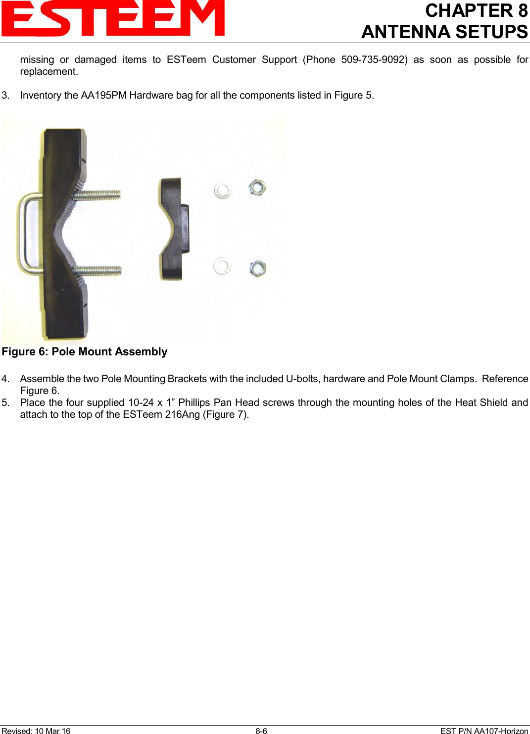
>
Electronic Systems Technology
>
HZN216AN User Manual
User Manual
Navigation menu
Upload a User Manual
Namespaces
Wiki Guide
HTML
PDF
Info
Views
User Manual
Discussion / Help
Navigation
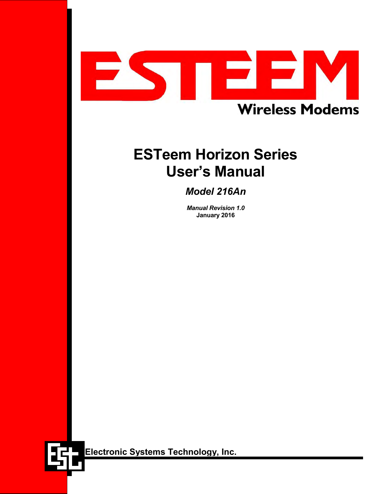
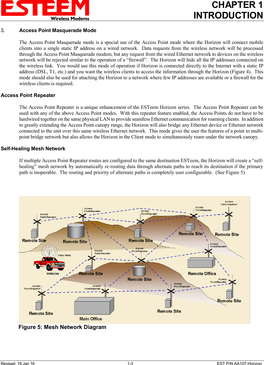
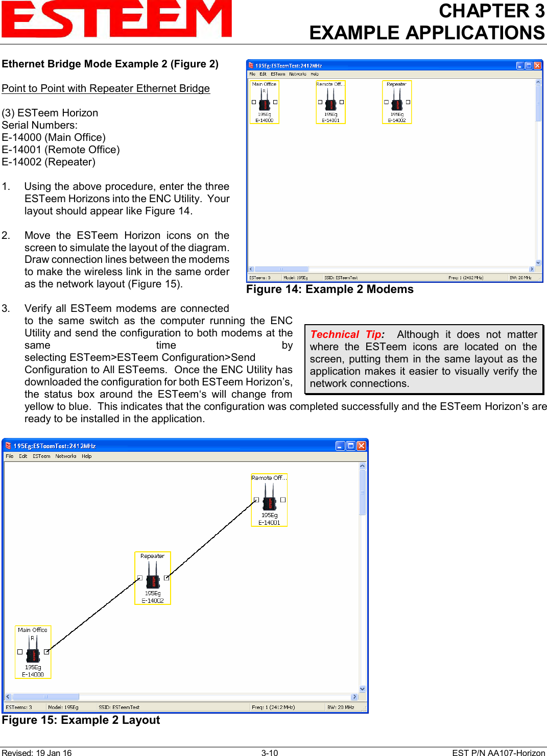
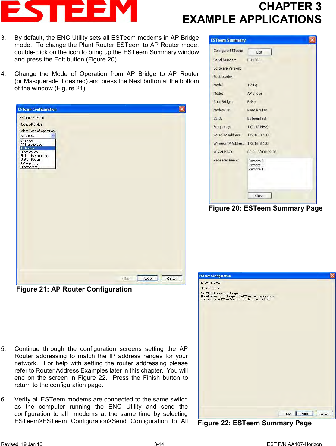
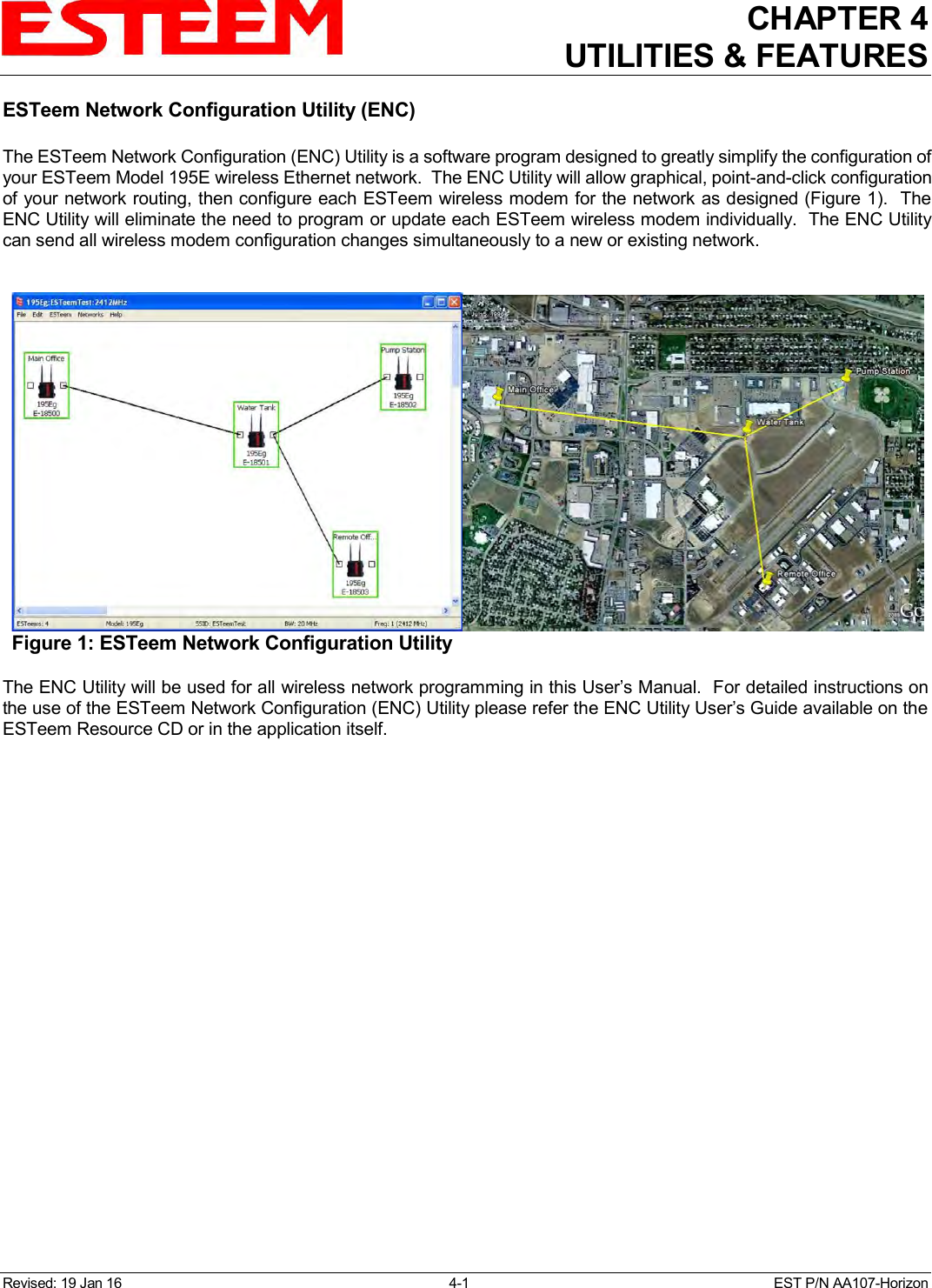

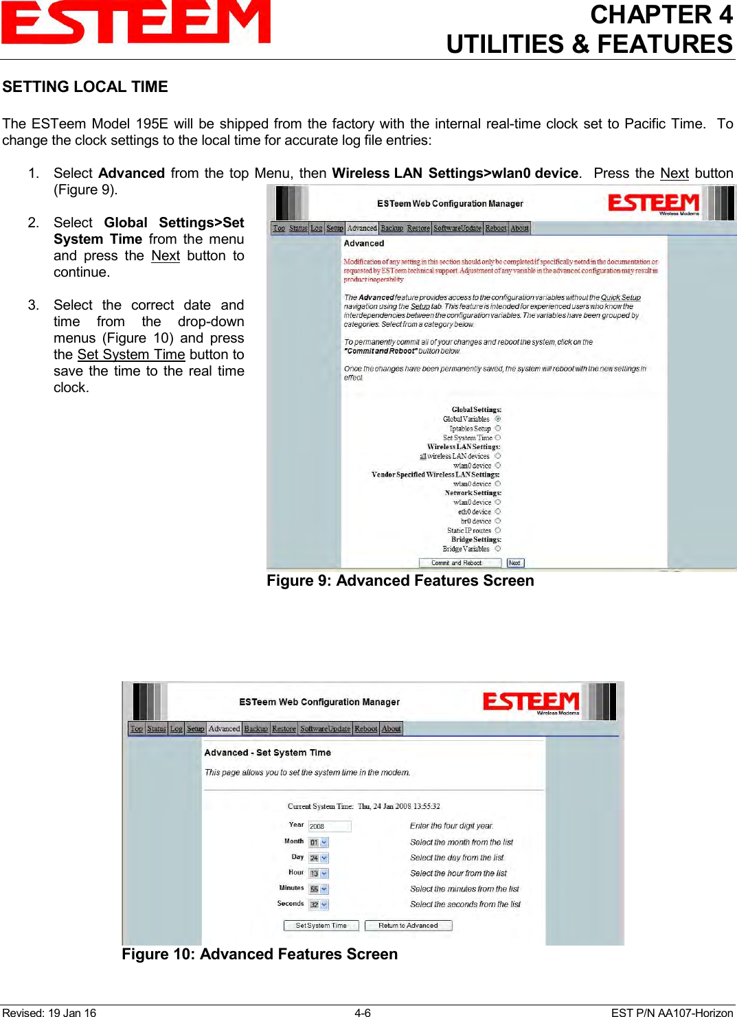
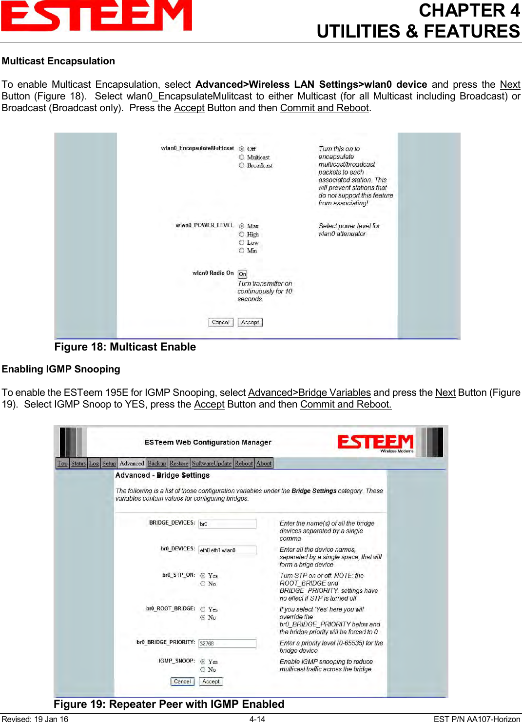
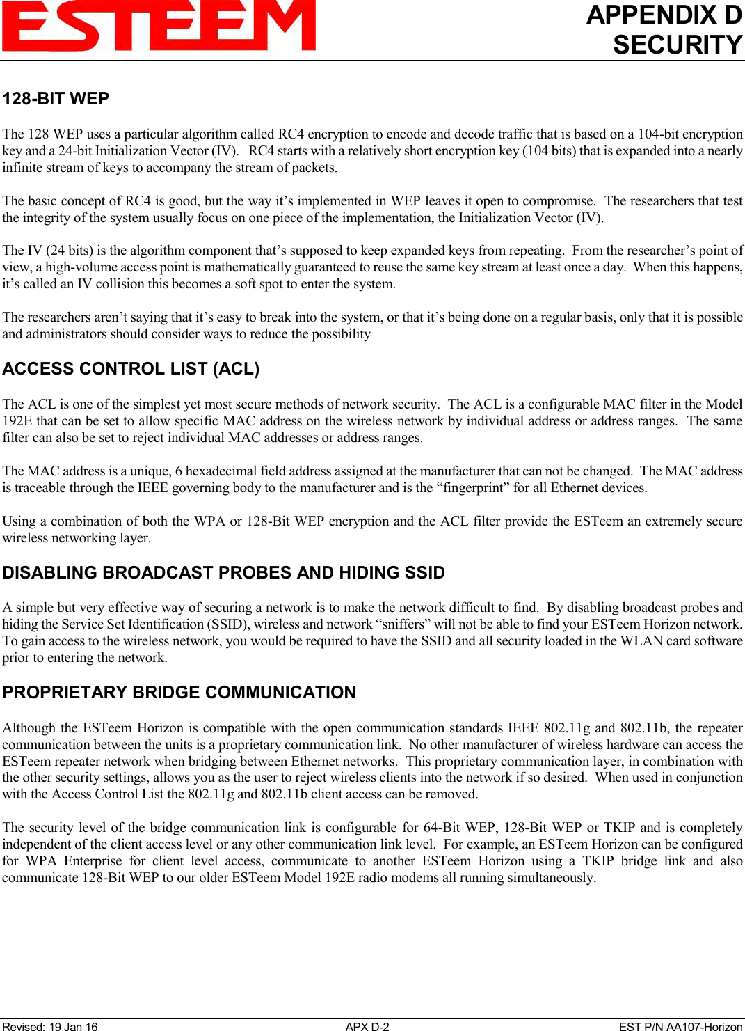
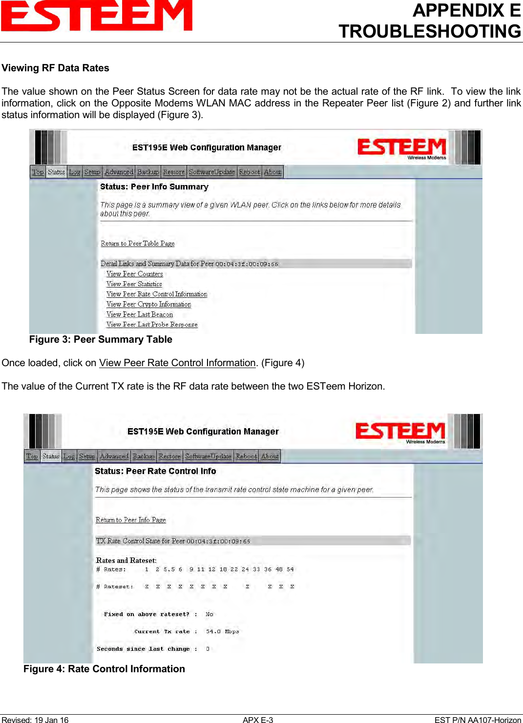
![CHAPTER 4 UTILITIES & FEATURES Revised: 19 Jan 16 4-15 EST P/N AA107-Horizon Simple Network Management Protocol (SNMP) The ESTeem 195E supports SNMP Version 1 (SNMPv1) and Version 2 (SNMPv2c) protocol. This protocol enables any SNMP server to view the status of the wireless network while the system is in operation. The following are a list of the Management Information Base (MIB) items that are supported in the ESTeem 195E and their MIB location: MIB Name MIB Directory Location Notes System Temperature EST-MIB::sysInternalTemp.0 in C * 1000 Uptime HOST-RESOURCES-MIB::hrSystemUptime.0 System Update ModemID EST-MIB::sysIdentifier.0 User-specified “nickname” for ESTeem Serial Number EST-MIB::sysSerialNumber.0 ESTeem serial number Model EST-MIB::sysModel.0 ESTeem model number Firmware Version EST-MIB::sysFirmwareRevision.0 Firmware revision System Mode EST-MIB::sysMode.0 AP_BRIDGE/STA_ETHERSTA, etc Free Memory UCD-SNMP-MIB::memTotalFree.0 Total Free Memory Idle CPU UCD-SNMP-MIB::ssCpuIdle.0 Percentage of CPU Idle [[ per-interface ]] IP Address IF-MIB::ifAddress Port Speed IF-MIB::ifSpeed In bps Port Status IF-MIB::ifOperStatus Mac Address IF-MIB::ifPhysAddress [[ per-wlandev entry ]] EST-MIB::wirelessDevicesNumber.0 Wireless Port Identification Device Name EST-MIB::wirelessDeviceTable.1.wName.1 Name of device (wlan0 standard) MAC Address EST-MIB::wirelessDeviceTable.1.wMacAddress.1 MAC address of WLAN port Mode EST-MIB::wirelessDeviceTable.1.wMode.1 Current Mode ap=access point, sta=station mode and airscope Frequency EST-MIB::wirelessDeviceTable.1.wFreq.1 Frequency in MHz Bandwidth EST-MIB::wirelessDeviceTable.1.wBandwidth.1 Bandwidth (5, 10, or 20 MHz if used) SSID EST-MIB::wirelessDeviceTable.1.wSSID.1 Service Set Identification BSSID EST-MIB::wirelessDeviceTable.1.wBSSID.1 Basic Service Set Identification Operational Rates EST-MIB::wirelessDeviceTable.1.wOpRates.1 List of RF Data Rates in Rate Set Basic Rates EST-MIB::wirelessDeviceTable.1.wBasRates.1 List of RF Basic Rates for status messages](https://usermanual.wiki/Electronic-Systems-Technology/HZN216AN/User-Guide-2988780-Page-51.png)
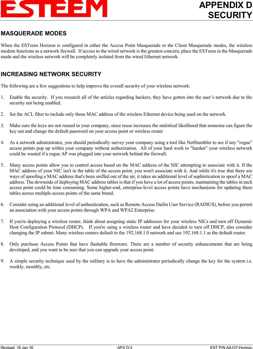
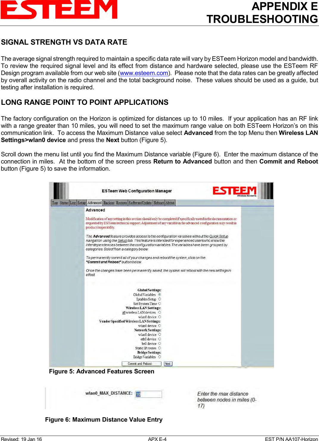
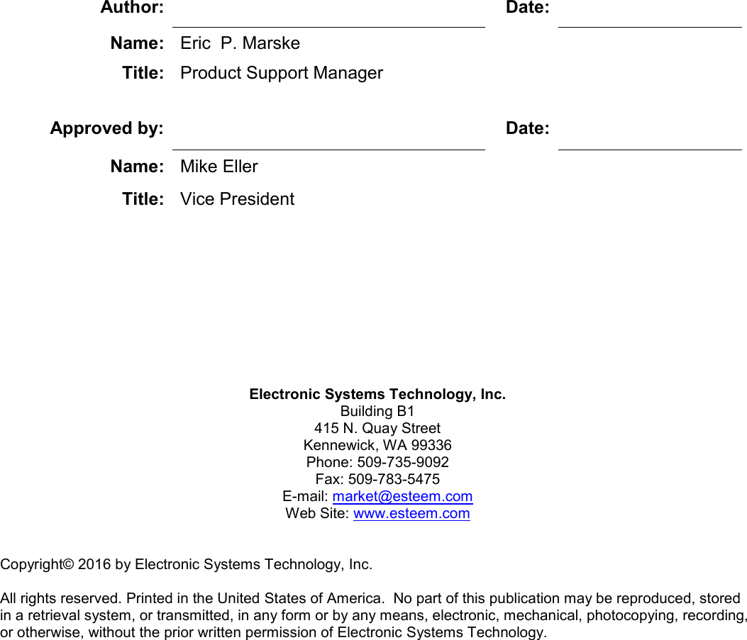
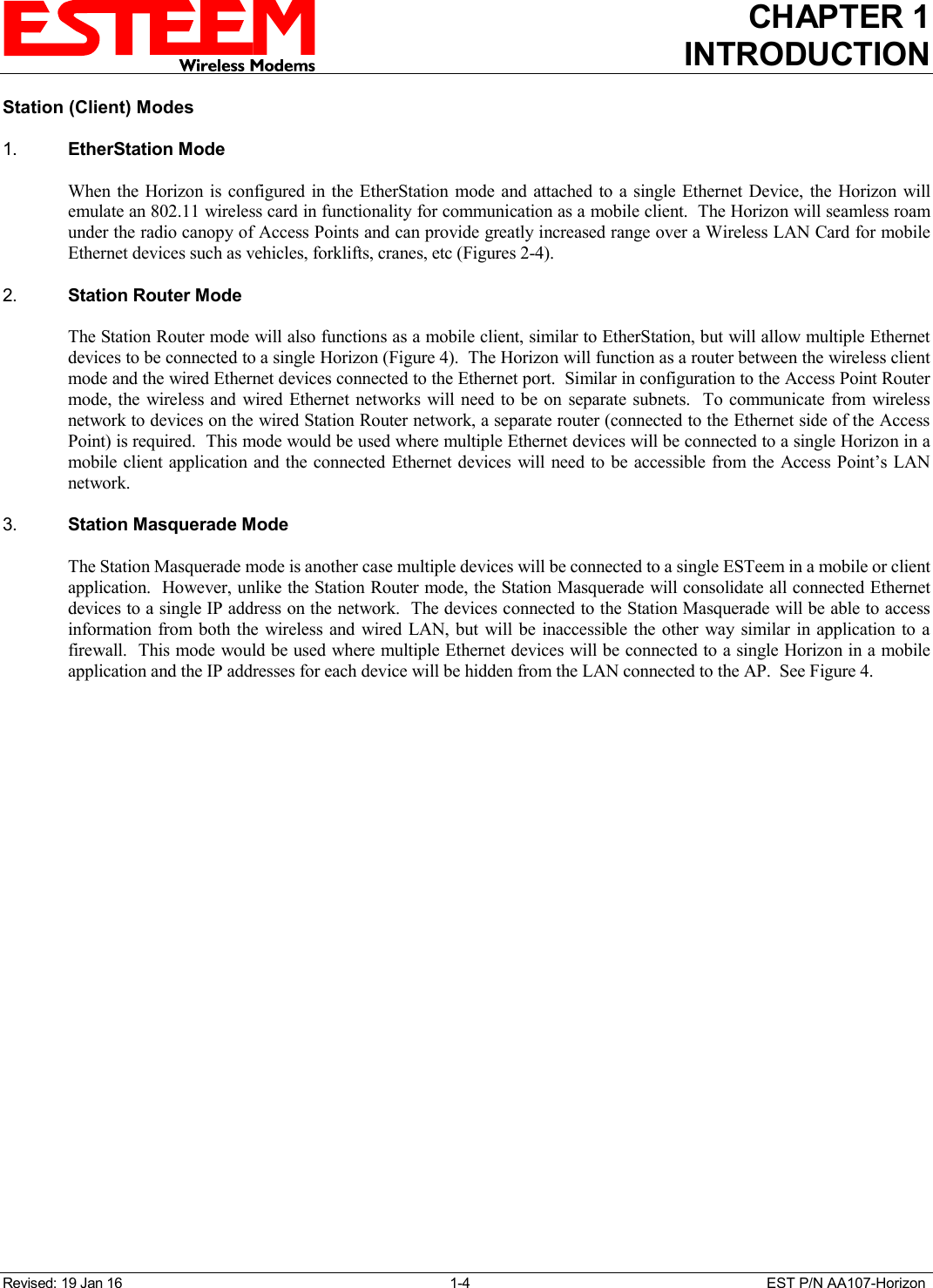
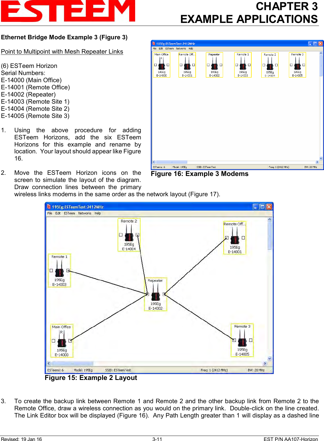
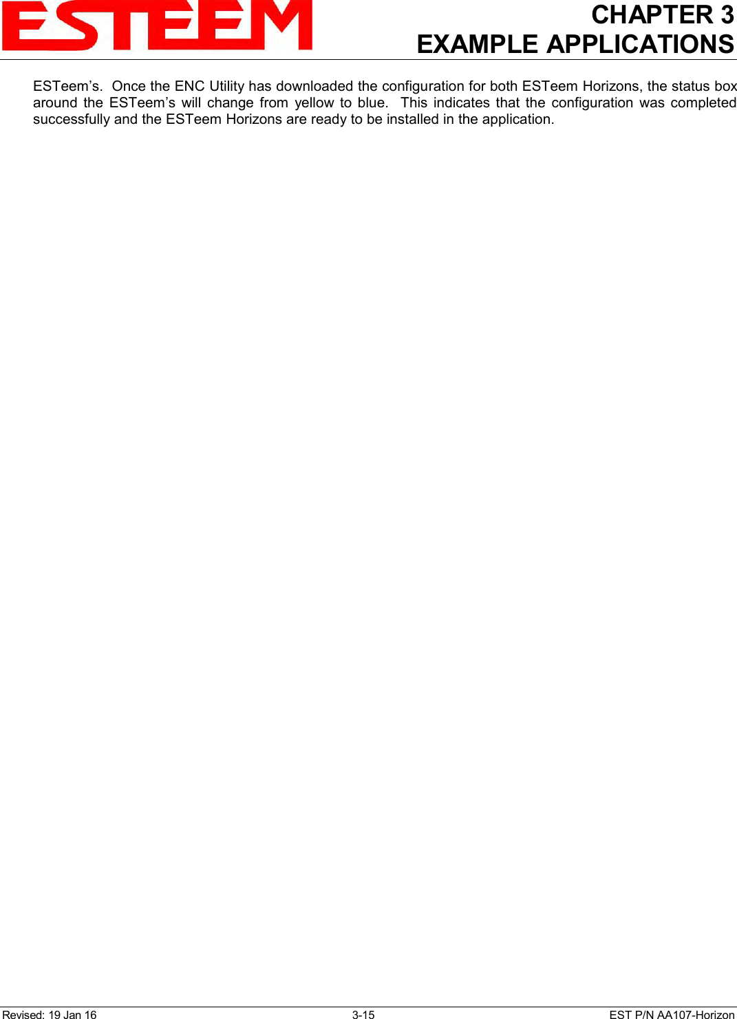
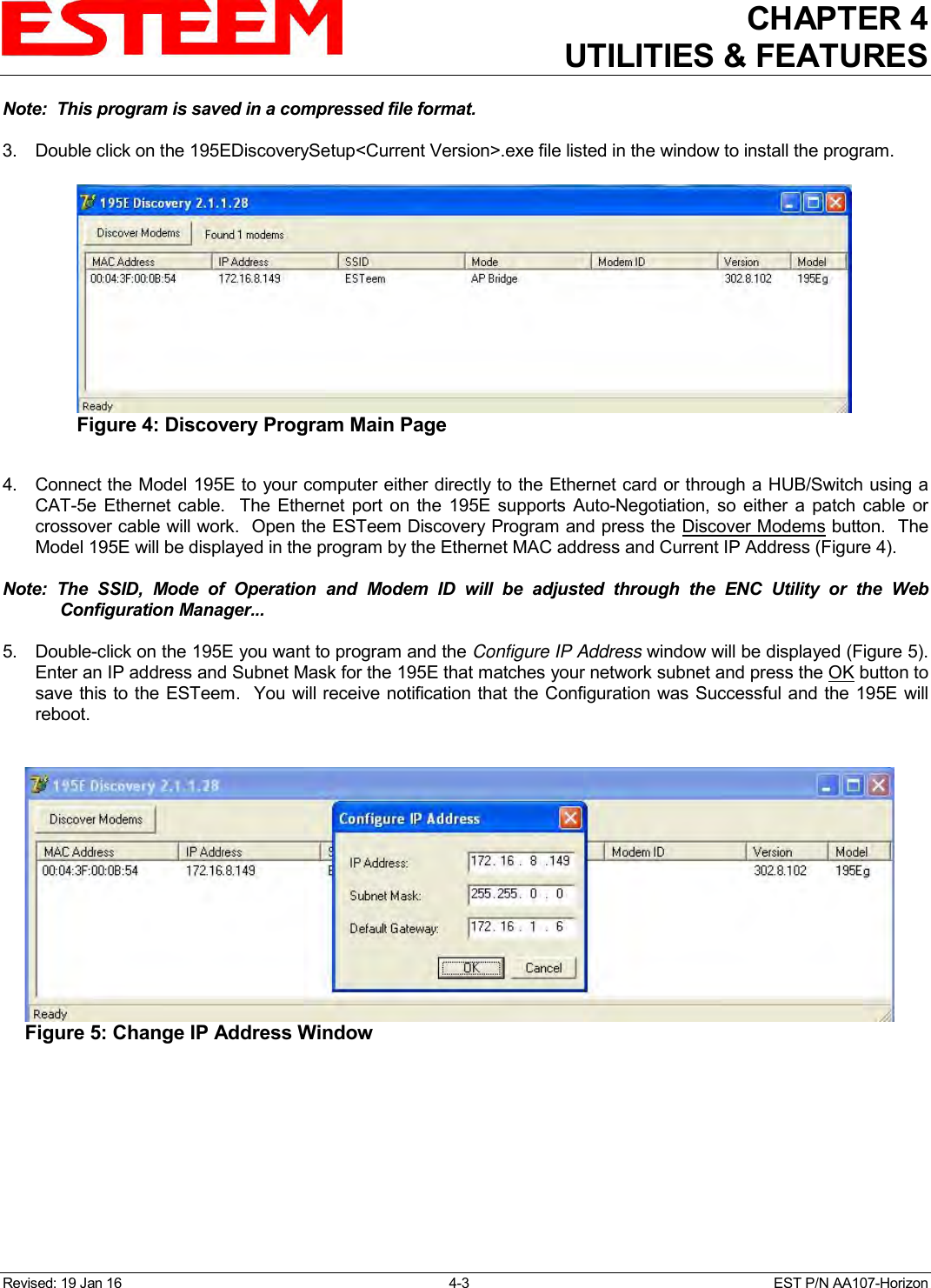
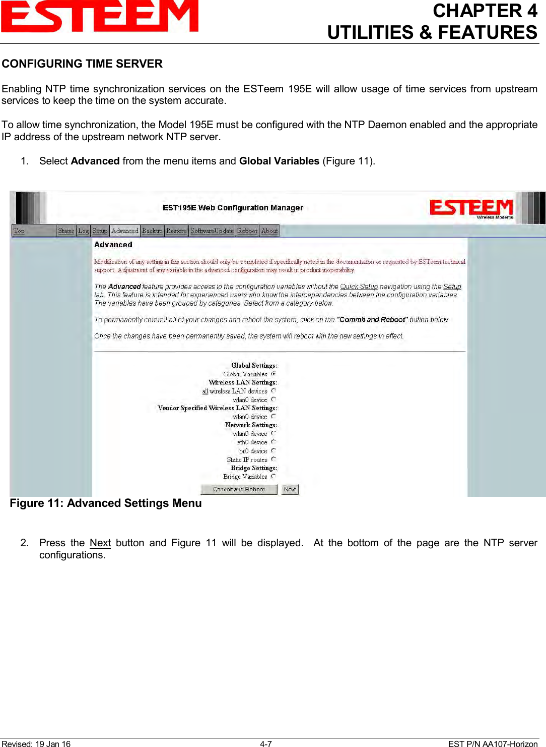
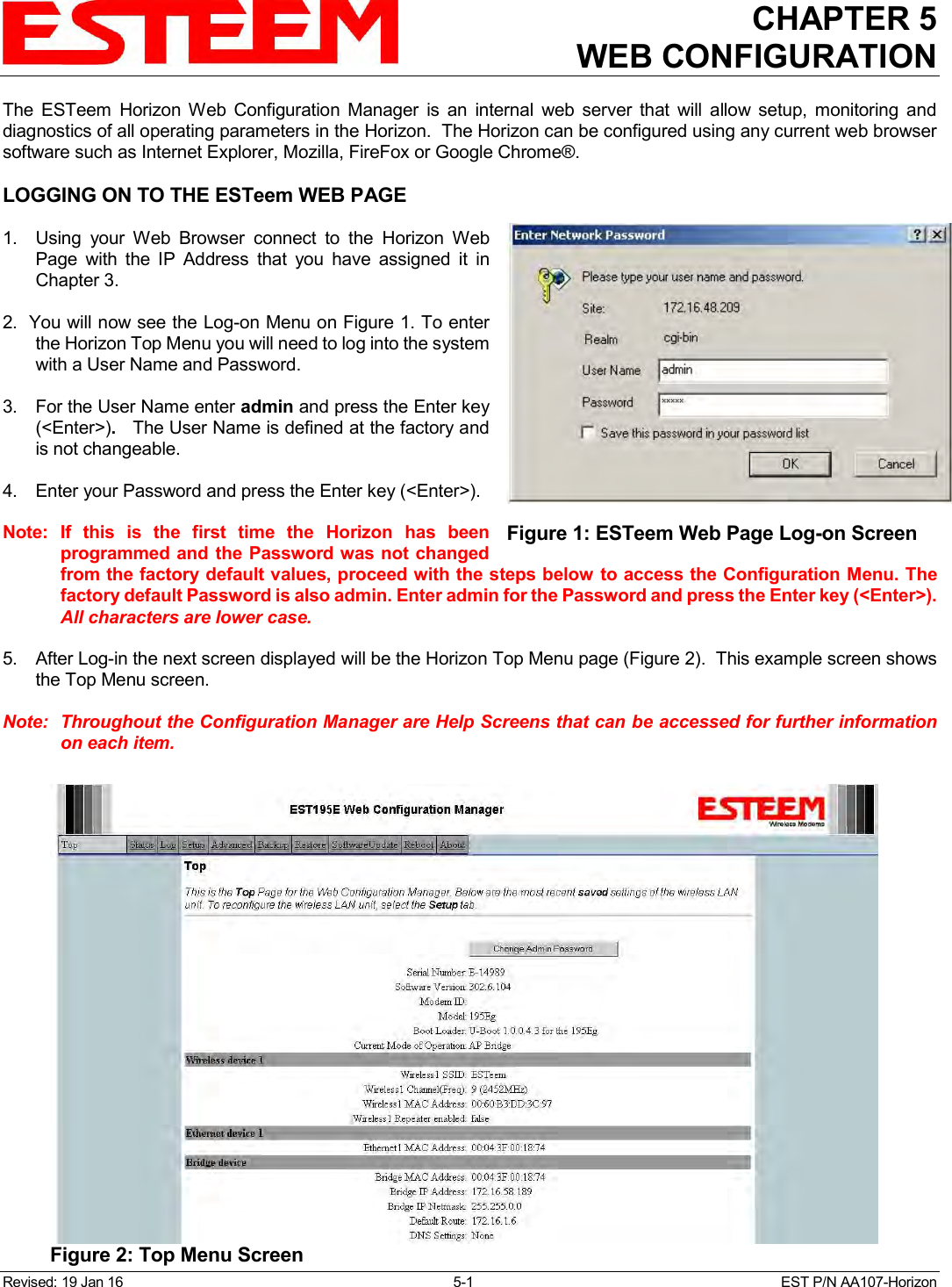
![CHAPTER 4 UTILITIES & FEATURES Revised: 19 Jan 16 4-16 EST P/N AA107-Horizon [[ peer table entry ]] All entries in the Peer Table will have a device entry index, both ESTeem and other wireless devices EST-MIB::wirelessPeersNumber.0 Total number of peer entries in table wlan device EST-MIB::wirelessPeerTable.1.pDevice.1 index into the wirelessDeviceTable (each entry will have a unique number Peer MAC Address EST-MIB::wirelessPeerTable.1.pMacAddr.1 MAC address of peer isRepeater? EST-MIB::wirelessPeerTable.1.pRepeater.1 Is the peer an ESTeem repeater isAP? EST-MIB::wirelessPeerTable.1.pAP.1 Is the peer an Access Point isAssocSta? EST-MIB::wirelessPeerTable.1.pAssoc.1 Is the peer an Mobile Client isAdhoc? EST-MIB::wirelessPeerTable.1.pAdhoc.1 Is the peer an AdHoc Station (802.11 only) Frequency EST-MIB::wirelessPeerTable.1.pFreq.1 Frequency in MHz current rate set EST-MIB::wirelessPeerTable.1.pCurRates.1 Current Operating Rates last rx signal EST-MIB::wirelessPeerTable.1.pSignal.1 Receive Signal in –dBm last rx noise EST-MIB::wirelessPeerTable.1.pNoise.1 Background Noise in –dBm BSSID EST-MIB::wirelessPeerTable.1.pBssid.1 Basic Service Set ID (In Hex) SSID EST-MIB::wirelessPeerTable.1.pSSID.1 SSID in Text isValid? EST-MIB::wirelessPeerTable.1.pCurrent.1 True if peer info is for a “current” peer. last rx EST-MIB::wirelessPeerTable.1.pLastRxl.1 seconds since last received packet from peer last tx EST-MIB::wirelessPeerTable.1.pLastTx.1 seconds since last transmitted packet to peer current tx rate EST-MIB::wirelessPeerTable.1.pCurrentRate.1 current tx rate in bps. Downloading MIB Tables To download the MIB items listed above and import into your SNMP server, log into any ESTeem 195E and select the About page (Figure 20). Press the Download MIB Files hyperlink on the page and save the files to your computer. Figure 20: MIB Table Download](https://usermanual.wiki/Electronic-Systems-Technology/HZN216AN/User-Guide-2988780-Page-52.png)
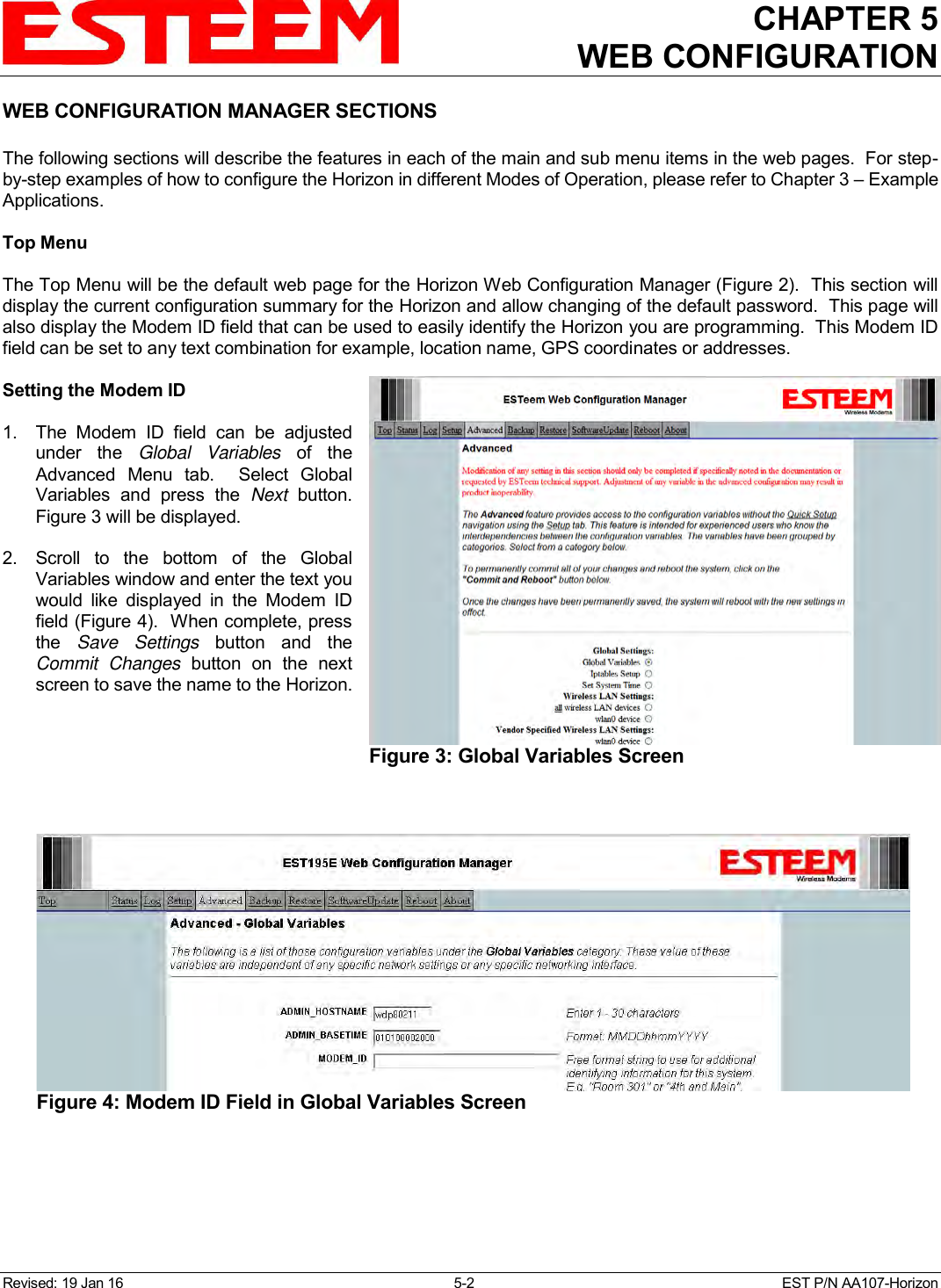

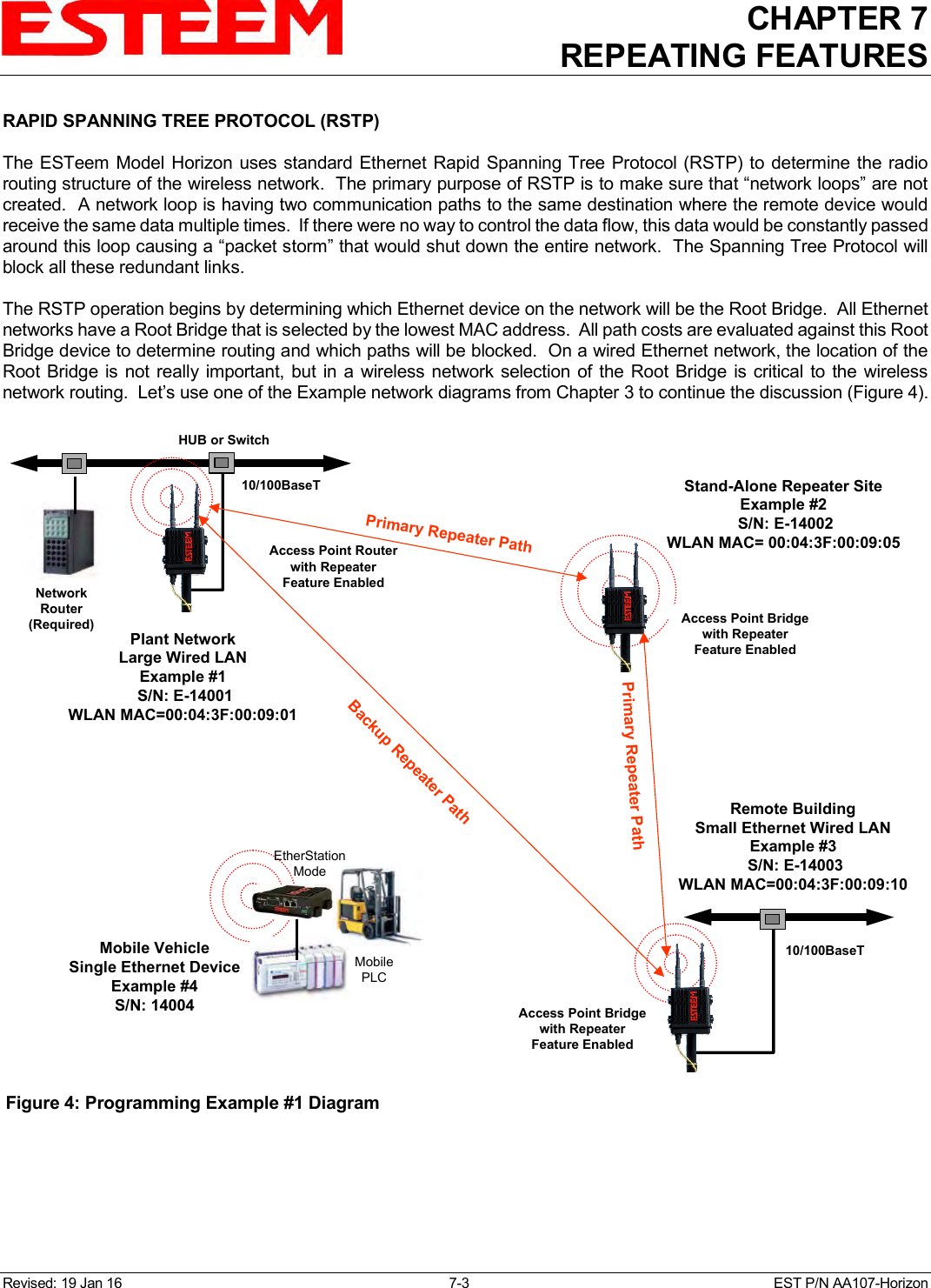
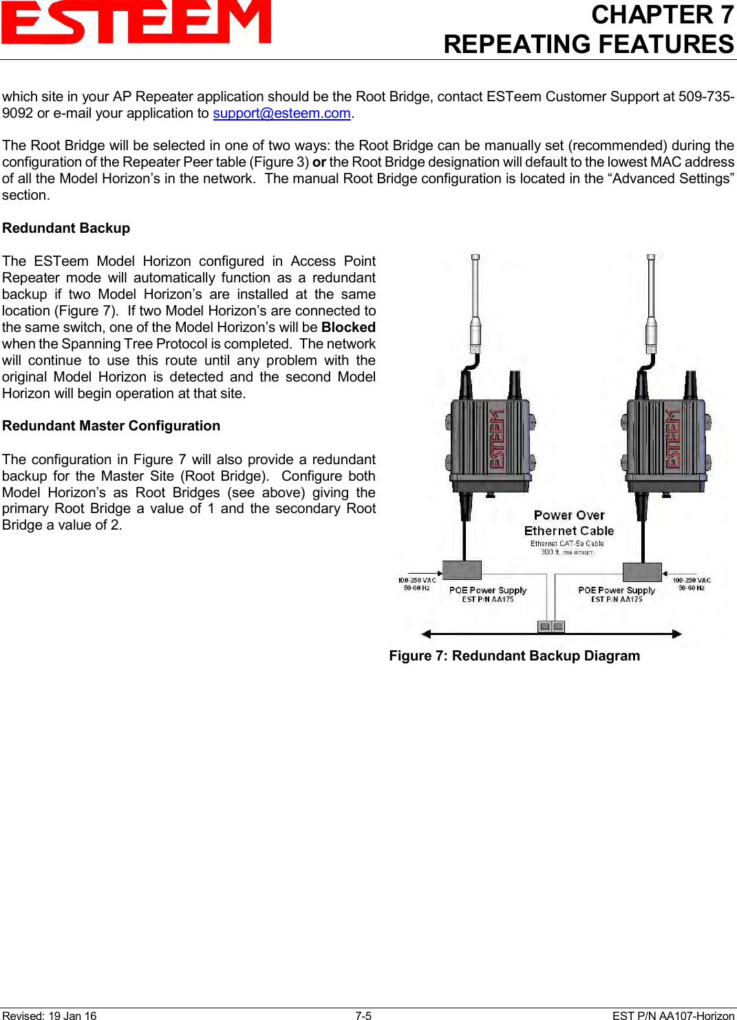
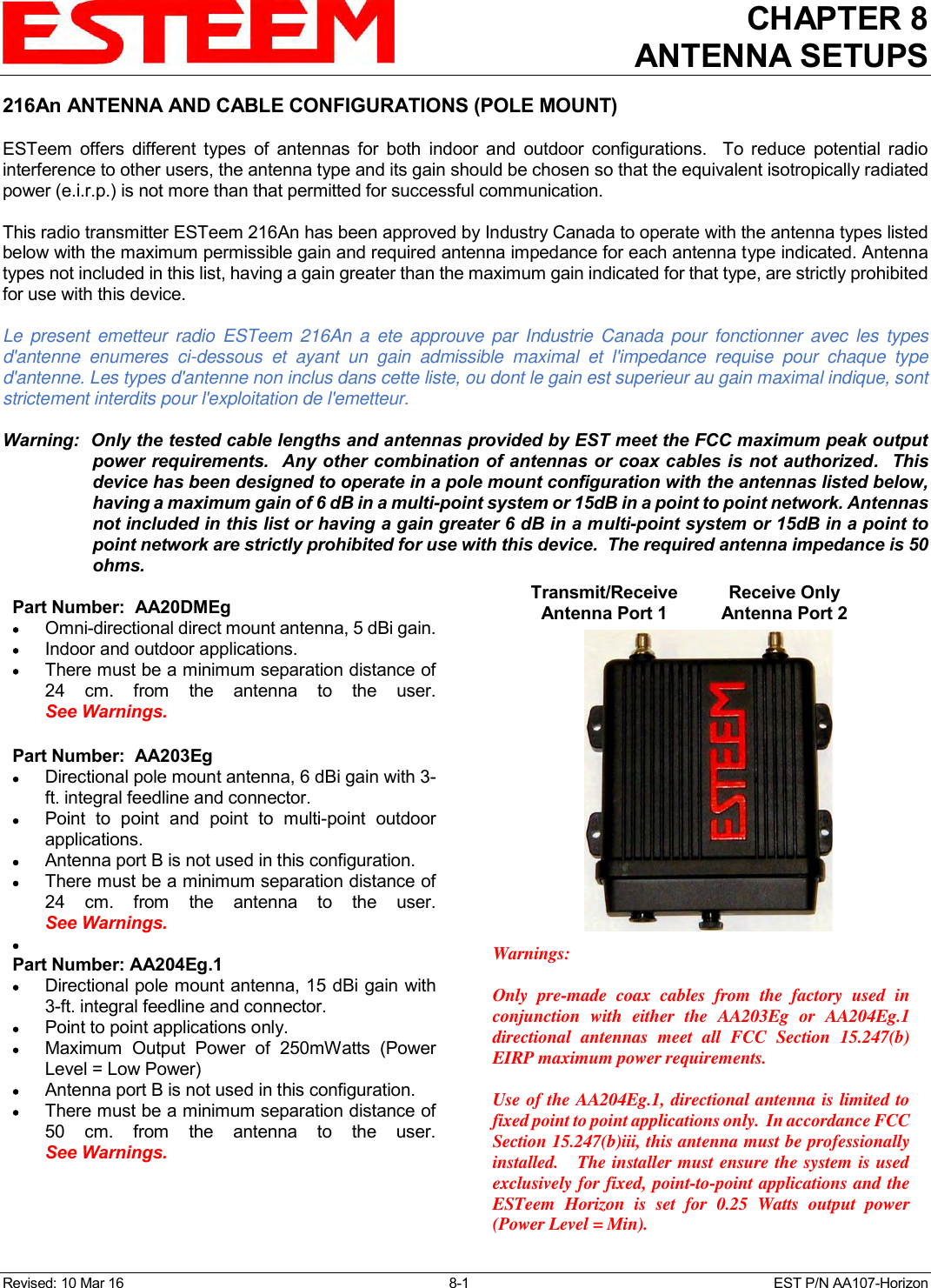
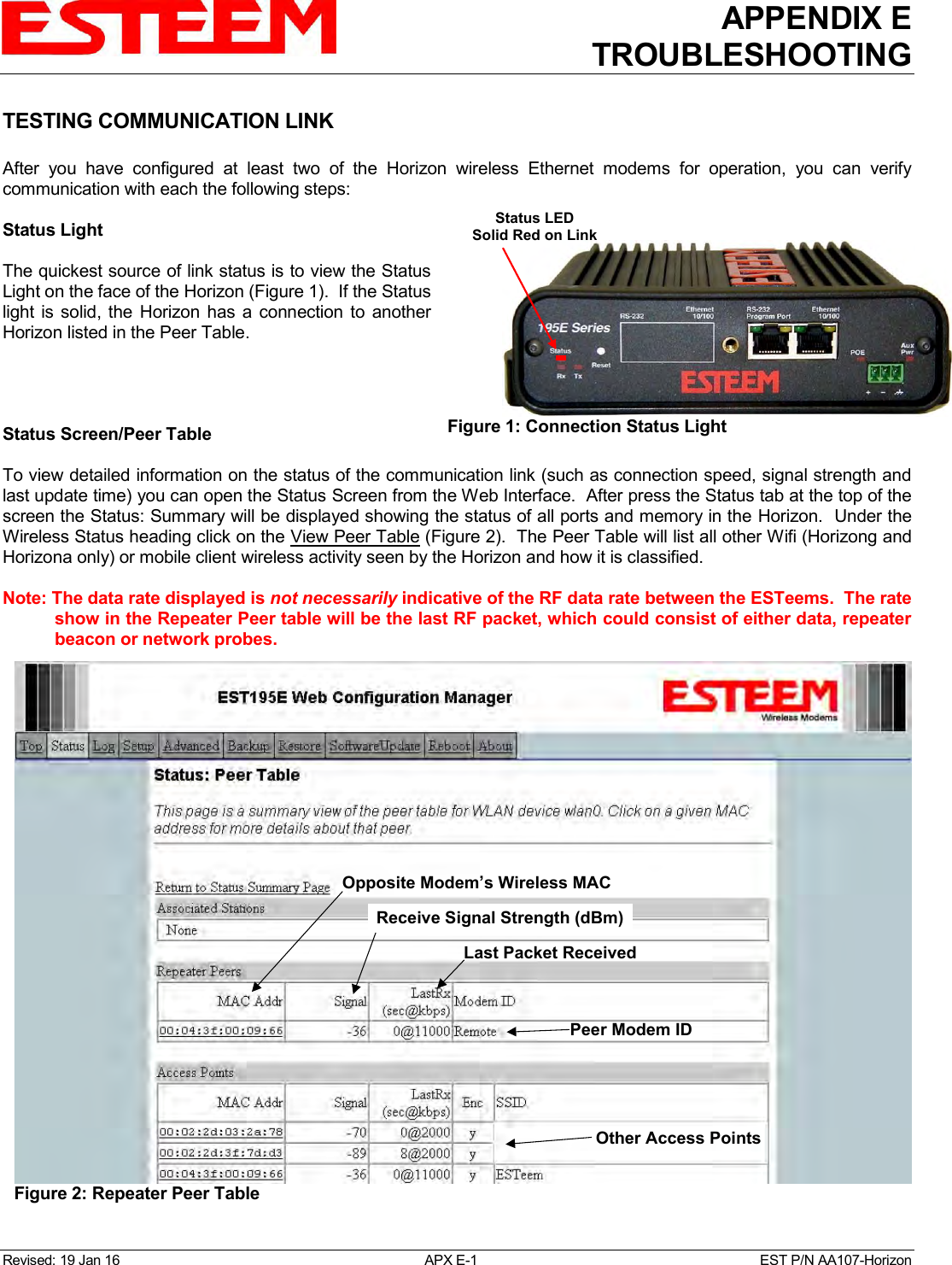
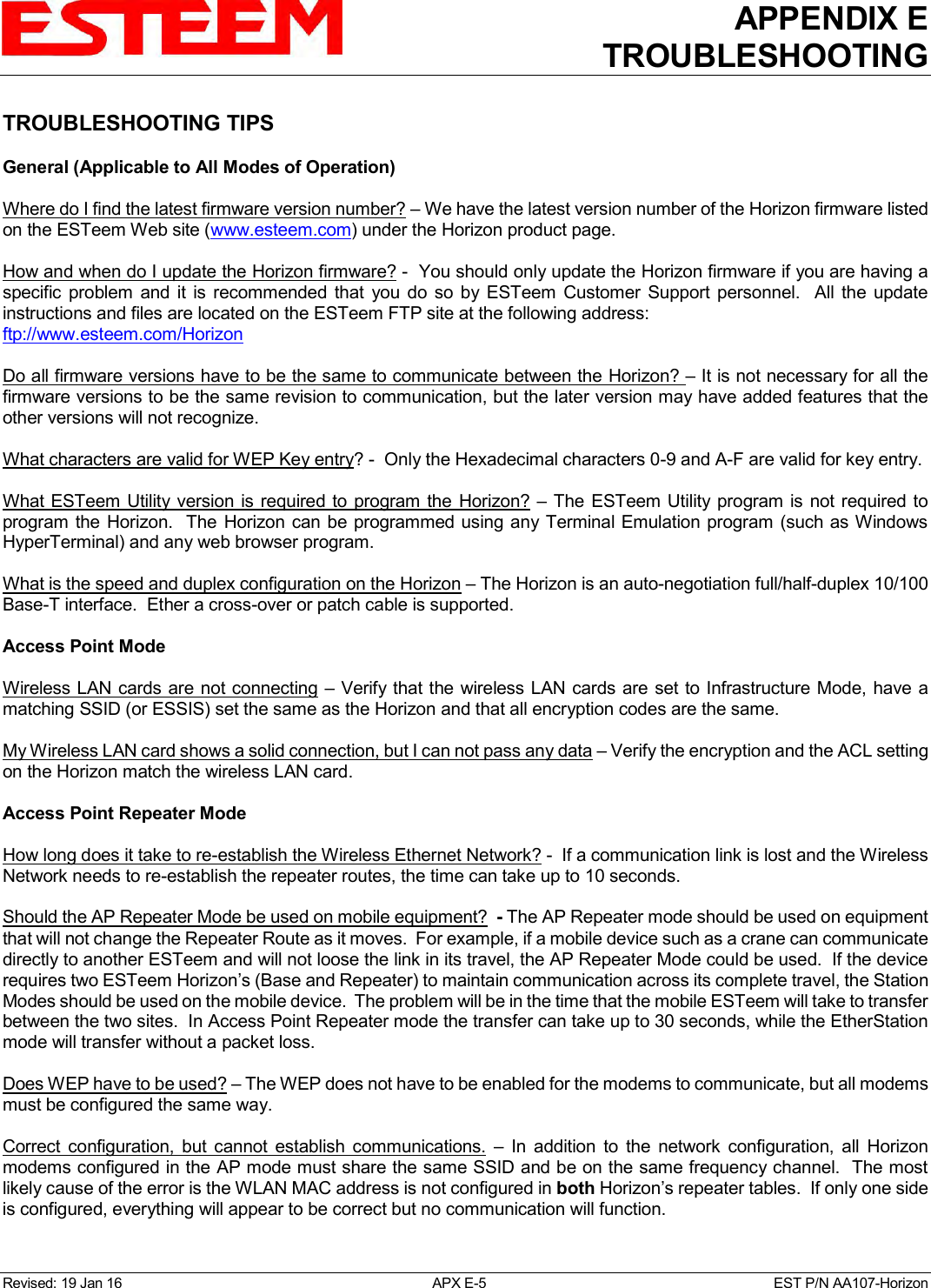
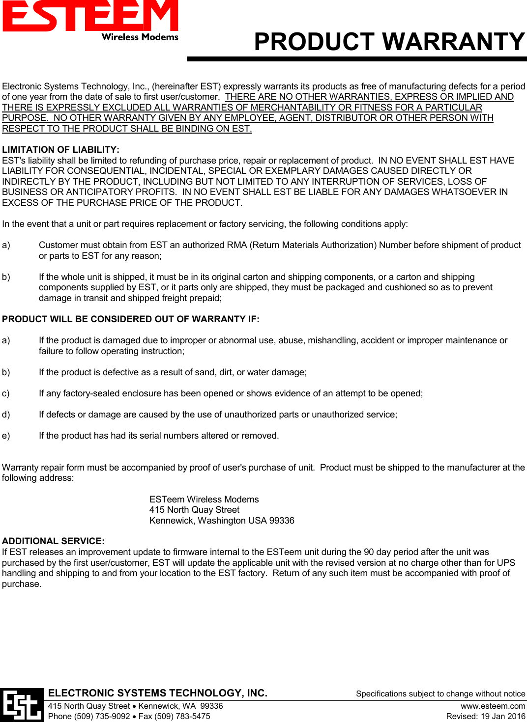
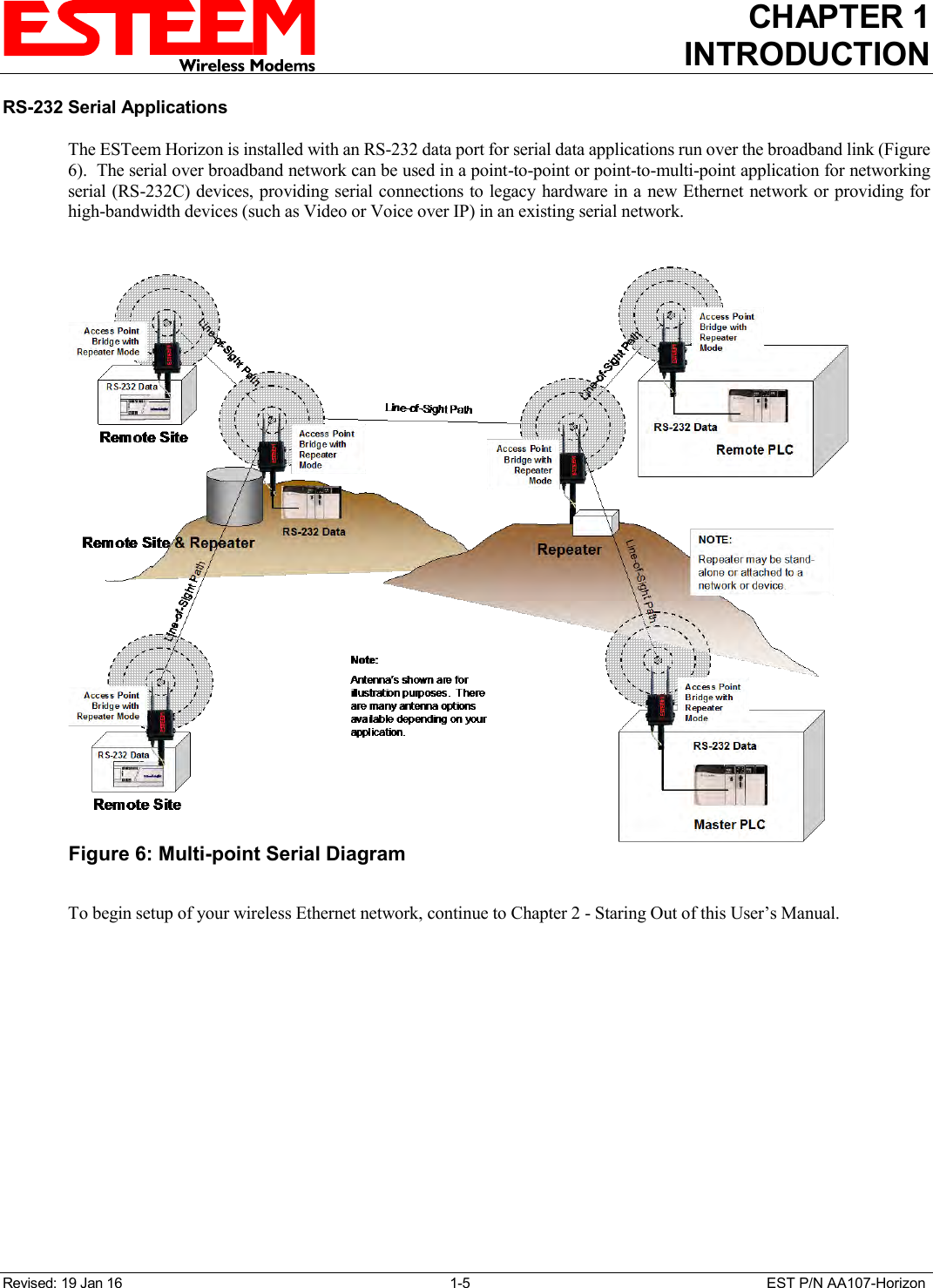
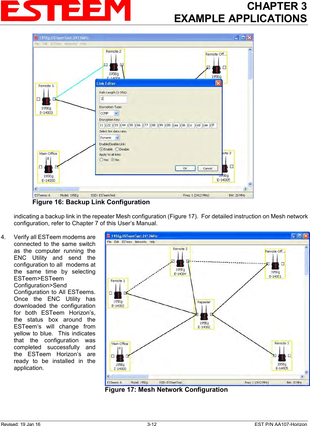
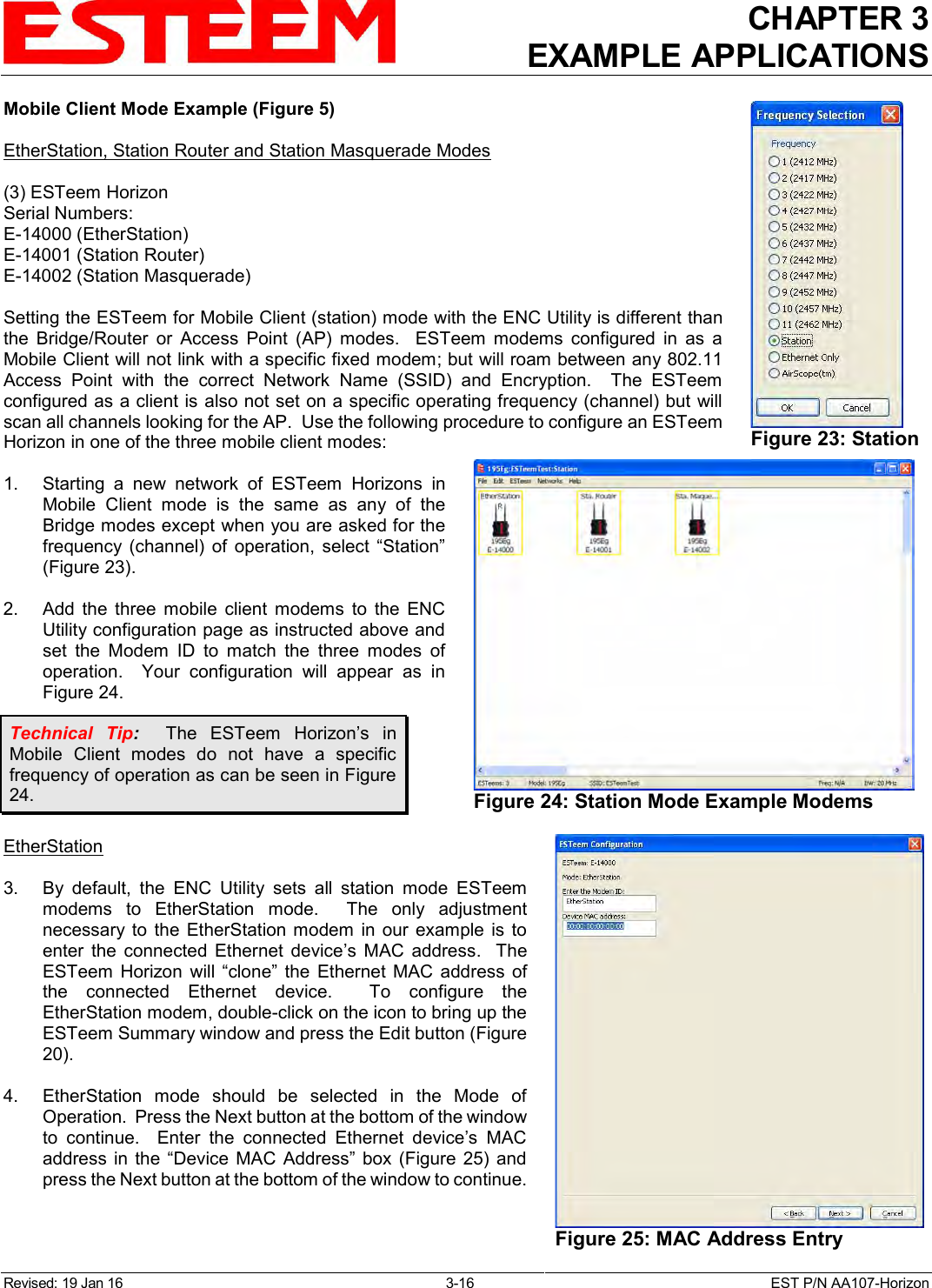
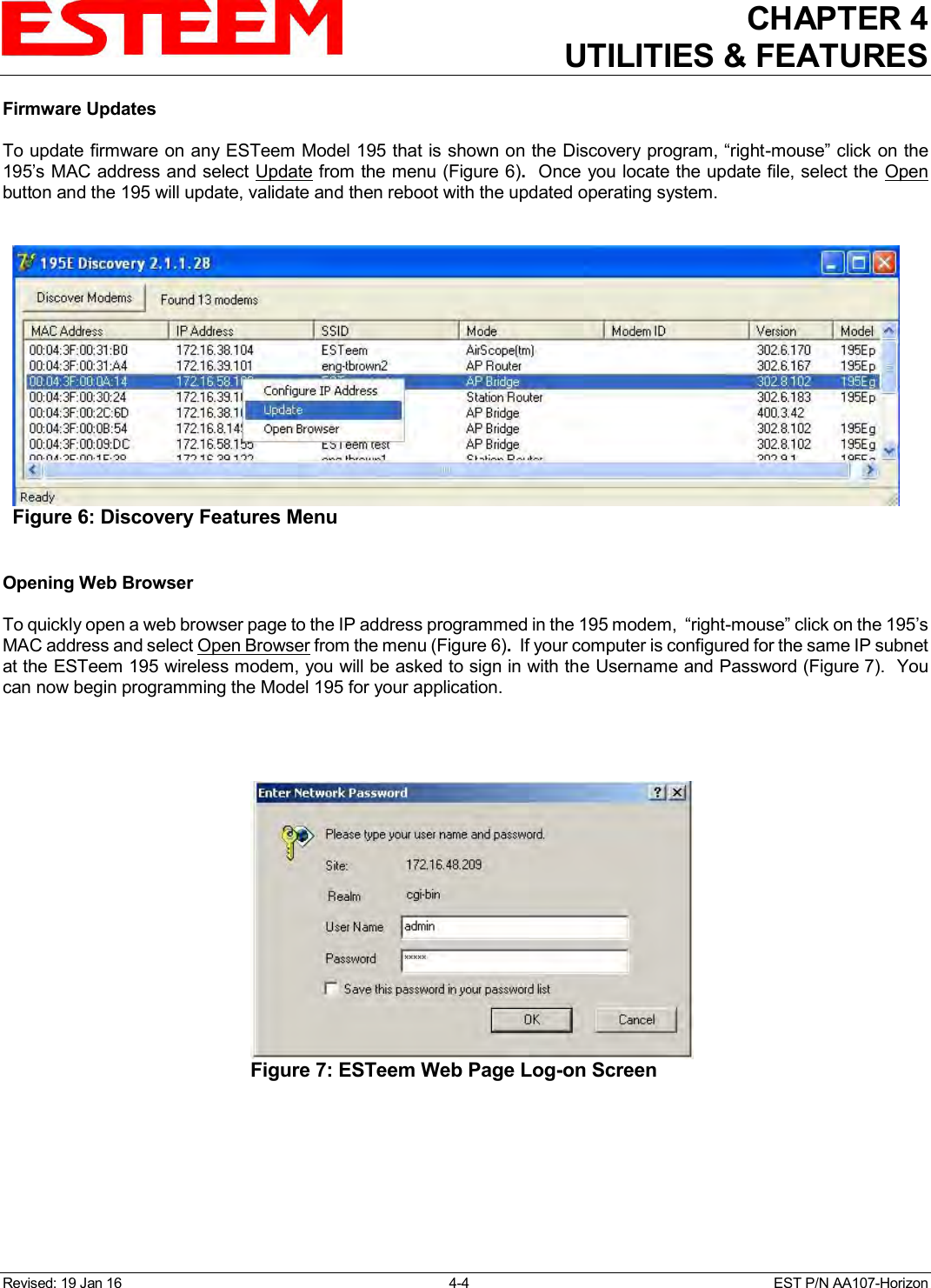
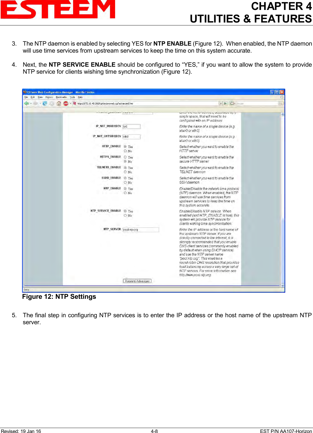
![CHAPTER 8 ANTENNA SETUPS Revised: 10 Mar 16 8-12 EST P/N AA107-Horizon FRESNEL ZONE The Fresnel zone shows the ellipsoid spread of the radio waves around the visual line-of-sight after they leave the antenna (see Figure 15). This area must be clear of obstructions or the signal strength will be reduced due to signal blockage. Typically, 20% Fresnel Zone blockage introduces little signal loss to the link. Beyond 40% blockage, signal loss will become significant. This calculation is based on a flat earth. It does not take into account the curvature of the earth. It is recommended for RF path links greater than 7 miles to have a microwave path analysis done that takes the curvature of the earth and the topography of the terrain into account. Fresnel Zone Radius = 72.1 SQRT [(d1d2) / (F (d1 + d2)] Units Fresnel Zone Radius in feet. d1 and d2 in statue miles F in GHz Figure 15: Fresnel Zone Diagram](https://usermanual.wiki/Electronic-Systems-Technology/HZN216AN/User-Guide-2988780-Page-83.png)