Electronics LS2P Self Contained Door Lock, LS2P User Manual Manual
International Electronics Inc. Self Contained Door Lock, LS2P Manual
Manual

IEI DoorGard LS2/LS2P
Programming Manual
www.ieib.com Part Number 6041000
Copyright 2003 Rev. 1.0
International Electronics, Inc. Date: 02-03
D3

For more information, contact:
International Electronics, Inc. © Copyright 2003
427 Turnpike Street International Electronics, Inc.
Canton, MA 02021 U.S.A. All Rights Reserved
Published in U.S.A.
Telephone: 781-821-5566
800- 733-9502 (sales in MA)
800-343-9502 (sales)
Fax: 781-821-4443
Fax
Information
Center: 781-821-0734
Internet: www.ieib.com
D3

Table of Contents
Foreword
F.1 About this Manual............................................... vii
F.2 Safety Warnings and Cautions ......................... vii
F.3 FCC Statement ..................................................... vii
F.4 Design Change Disclaimer.................................viii
F.5 Reproduction Disclaimer.................................... viii
F.6 Technical Support................................................ viii
F.7 Warranty ............................................................... ix
DoorGard LS2/LS2P System
Programming Guide
1.1 Features ................................................................. 1-1
1.1.1 Specifications.................................................. 1-2
1.1.2 Battery Powered............................................ 1-2
1.1.2.A Low Voltage Operation ...................... 1-2
1.1.2.B Low Voltage Warning ......................... 1-3
1.1.2.C Inhibit Operation Warning ................ 1-3
1.1.2.D Lock Prior to Sleep .............................. 1-3
1.2 Programming the Keypad.................................. 1-4
1.2.1 Master Code................................................... 1-4
1.2.2 User #2, Supervisor...................................... 1-5
1.3 Programming Keypad Options and
Parameters................................................................... 1-6
1.3.1 Set Lock Time ...........................................1-6
1.3.2 Propped and Forced Door Audio Alerts... 1-6
1.3.2.A Forced Door Audio Alert .................... 1-7
1.3.3 Propped Door Audio Alert.......................... 1-7
DoorGard LS2/LS2P System Programming Manual, D3 iii

1.3.4 Request-To-Exit (REX) Input .......................1-8
1.3.5 User Lockout Option ....................................1-8
1.3.5.A Lockout By Location ............................1-8
1.3.5.B Lockout By Group ................................1-9
1.3.6 Error Lockout Option ...................................1-10
1.3.7 Turning Audio Keypress Feedback
ON/OFF....................................................................1-10
1.3.8 Turning Visual LED/Keypress Indicator
ON/OFF....................................................................1-11
1.3.9 Auto Entry.......................................................1-12
1.3.10 TimeZone/Holiday Features ......................1-12
1.3.10.A Midnight Crossing TimeZones.........1-14
1.3.10.B Holidays................................................1-14
1.3.10.C Daylight Savings Time.......................1-14
1.3.10.D Leap Year.............................................1-15
1.3.10.E Time/Date Set.......................................1-15
1.3.11 Transaction Event Log................................1-15
1.3.12 Communications..........................................1-15
1.3.13 DoorGard LS2/LS2P Default Settings.......1-16
1.3.14 Restoring System Defaults .........................1-19
1.3.15 Erasing User Table/Restore System
Defaults.....................................................................1-19
1.4 Programming Users .............................................1-20
1.4.1 User Features..................................................1-20
1.4.2 User Codes......................................................1-22
1.4.3 Enabling/Disabling Users Command .........1-23
1.4.4 Adding New or Changing Existing
Codes.........................................................................1-23
1.4.4.A Examples ................................................1-24
1.5 Programming Commands ..................................1-26
Appendix A: Users Chart
Table of Contents
iv DoorGard LS2/LS2P System Programming Manual, D3

List of Tables
Table 1-1. Specifications.......................................1-2
Table 1-2. DoorGard LS2/LS2P Default
Settings.................................................1-16
Table 1-3. DoorGard LS2/LS2P LED
Indicators/Sounder Operations........1-17
Table 1-4. User Types...........................................1-21
Table 1-5. Program Commands..........................1-26
DoorGard LS2/LS2P System Programming Manual, D3 v

Foreword
F.1 About this
Manual
This manual is designed for installers of the Interna-
tional Electronics DoorGard LS2/LS2P system. All pro-
gramming instructions and other relevant information
is contained in this manual.
This manual describes all the features currently sup-
ported in the LS2/LS2P hardware only. It does not
cover any of the features or functionality in the PDA
or Hubmanager Pro 4.x software. Please refer to those
respective manuals for those details.
F.2 Safety
Warnings and
Cautions
When handling the main printed circuit board, to
guard against possible static discharges, touch a
grounded object BEFORE touching the DoorGard
LS2/LS2P system. Static shock can render the product
unusable. Commands mentioned in the description
paragraph are all listed in Table 1-4.
F.3 FCC Statement This equipment has been tested and found to comply
with the limits for a Class B digital device, pursuant to
Part 15 of the FCC Rules. These limits are designed to
provide reasonable protection against harmful inter-
ference in a residential installation. This equipment
generates, uses, and can radiate radio frequency en-
ergy and, if not installed and used in accordance with
the instructions, may cause harmful interference to
radiocommunications. However,thereisnoguaran-
tee that interference will not occur in a particular in-
stallation. If this equipment does cause harmful inter-
ference to radio or television reception, which can be
determined by turning the equipment off and on, the
user is encouraged to try to correct the interference by
one or more of the following measures:
•Reorient or relocate the receiving antenna
DoorGard LS2/LS2P System Programming Manual, D3 vii

•Increase the separation between the equipment
and receiver
•Connect the equipment into an outlet on a circuit
different from that to which the receiver is con-
nected
•Consult the dealer or an experienced radio/televi-
sion technician for help
Any changes or modifications not expressly approved
by the party responsible for compliance could void the
user’s authority to operate the equipment.
The term “IC:” before the radio certification number
only signifies that Industry of Canada technical speci-
fications were met.
F.4 Design Change
Disclaimer
Due to design changes and product improvements,
information in this manual is subject to change without
notice.
IEI assumes no responsibility for any errors that may
appear in this manual.
F.5 Reproduction
Disclaimer
Neither this manual nor any part of it may be repro-
duced, photocopied, or electronically transmitted in
any way without the written permission of IEI.
F.6 Technical
Support
Should you experience any difficulty programming
the DoorGard LS2/LS2P system, please contact your
IEI representative, or IEI at the number listed on page
ii.
To contact IEI’ Technical Support department, call 1-
800-343-9502 between 8:00 a.m. - 7:00 p.m. (Eastern
Standard Time), Monday through Friday. Questions
can also be submitted through our website at
www.ieib.com.
Foreword
viii DoorGard LS2/LS2P System Programming Manual, D3

F.7 Warranty International Electronics Incorporated (IEI) warrants
its products to be free from defects in material and
workmanship, when they have been installed in ac-
cordance with the manufacturer’s instructions, and
have not been modified or tampered with. IEI does not
assume any responsibility for damage or injury to per-
son or property due to improper care, storage han-
dling, abuse, misuse, normal wear and tear, or an act
of God.
IEI’s sole responsibility is limited to the repair (at IEI’s
option) or the replacement of the defective product or
part when sent to IEI’s facility (freight and insurance
charges prepaid), after obtaining IEI’s Return Mer-
chandise Authorization. IEI will not be liable to the
purchaser or any one else for incidental or consequen-
tial damages arising from any defect in, or malfunction
of, its products.
This warranty shall expire two years after shipping
date for the DoorGard LS2/LS2P system. Except as
stated above, IEI makes no warranties, either ex-
pressed or implied, as to any matter whatsoever, in-
cluding, without limitation to, the condition of its prod-
ucts, their merchantability, or fitness for any particular
application.
Foreword
DoorGard LS2/LS2P System Programming Manual, D3 ix
DoorGard LS2/LS2P
System Programming
Guide
This guide provides information about programming
the DoorGard LS2/LS2P system. You must program
certain parameters, such as such as changing the de-
fault Master Code, upon initial installation.
NOTE: All features and programming commands
relating to proximity cards are available in the LS2P
model only.
1.1 Features The following is a list of features available in the
LS2/LS2P system.
•2000 Users
•2000 Transaction Log Events*
•32 Holidays*
•8 Timezones*
•Auto-Unlock (default = 9:00 A.M. to 5:00 P.M.)
•Proximity Card Reader+
•PDA Communications*
•8UserTypes
•Propped and Forced Door Audio Alerts
•REX
•User Lockout
* Means a feature is only available with software.
+ Available in LS2P model only.
DoorGard LS2/LS2P System Programming Manual, D3 1-1
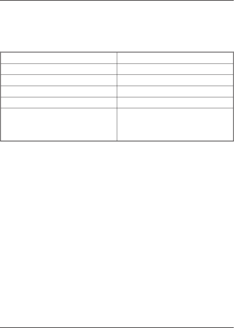
1.1.1 Specifications
Table 1-1. Specifications
Voltage 6 Volts (four 1.5-volt AA batteries)
Current Draw (sleep mode) 30 mA
REX Normally Open Dry Contact
Door Loop Normally Open Dry Contact
Temperature -35° C to +66° C (-31° F to +151° F)
Environment Indoor/Outdoor*
*The rear part of the system must be
indoors; only the keypad can be
outside.
1.1.2 Battery Powered The DoorGard LS2/LS2P system is battery powered;
when the system is not in use, it consumes very little
power, but the batteries normally discharge over an
extended period. The DoorGard LS2/LS2P system
powers itself down (sleep mode) after one of the fol-
lowing events:
•fifteen seconds after the last keypress that does
not result in an unlock
•immediately after sending the lock pulse regard-
less of what triggered it (valid PIN, REX input,
Toggle/Passage code, etc..)
•fifteen seconds after a Lockout code is entered
•immediately after a Toggle/Passage ON/OFF code
is entered
1.1.2.A Low Voltage Operation
The LS2/LS2P has two low voltage indicators, the Low
Voltage Warning and Low Voltage Inhibit. The system
wakes up momentarily every 30 seconds and checks
the battery voltage to determine if the voltage is low.
When either of these situations arises the battery
should be changed.
1.1 Features
1-2 DoorGard LS2/LS2P System Programming Manual, D3

1.1.2.B Low Voltage Warning
When the battery voltage drops to 4.4 volts, the Low
Voltage Warning is indicated by four long beeps after
any code is entered and then the lock energizes. This
action lets you know the batteries are getting low and
should be charged, but does not prevent you from
operating the door.
1.1.2.C Inhibit Operation Warning
When the battery pack voltage reaches below 4.0 volts
and a user enters his/her code, the DoorGard LS2/LS2P
sounder issues four (4) long beeps, pauses, then sound
another four (4) long beeps.
This lets you user know the batteries are so low that
sufficient power may not be present to perform a lock
pulse after the unlock pulse. At this point, the door
will not unlock.
To open the door now, either the Master code, Super-
visor code, or an Emergency code must be used (for
an explanation of user types,see Table 1-4). These three
types of users (Master, Supervisor, or Emergency)
override the Inhibit warning, allowing someone to
open the door and then change the batteries.
1.1.2.D Lock Prior to Sleep
The Lock Prior to Sleep option (command 30 option
14) determines if the keypad sends the lock pulse be-
fore the system goes to sleep. The default is “only if
necessary,” but you can set it to “always lock prior to
sleep” if required. Example:
30 # 14 # set/clear # **
(default—0=only if necessary,
1=always lock
prior to sleep)
1.1 Features
DoorGard LS2/LS2P System Programming Manual, D3 1-3
1.2 Programming
the Keypad
The first step in programming the system is to place
it into program mode. You can verify that the system
is in program mode as the yellow LED blinks slowly;
when the yellow LED stops blinking and is OFF com-
pletely, the system is no longer in program mode. If
the desired programming is not understood by the
system or is entered incorrectly, the yellow LED re-
mains steadily lighted; this signals that you should
press *to clear the error condition and then re-enter
the code. The system remains in program mode for 45
seconds if no key is pressed.
1.2.1 Master Code To place the system in program mode, you must first
enter 99 # followed by the “master code,” which is the
code that is stored in user location 1.
To place the system in program mode, press:
99 # Master Code *
NOTE: 1234 is the default master code, which IEI
recommends you change right away.
If you forget the master code, remove the battery cover,
take out the battery pack and control board (leave all
wires connected), and press the SW1 switch. (SW1 is
located next to pin 25 on J2, through a hole in the
bracket.)
A slow blinking yellow LED indicates that the system
is in program mode. (A steady yellow LED, in contrast,
means that errors were detected during programming.
Error states can be cleared by pressing the asterisk *
key.)
NOTE: For details about the master code, see the
Users section.
1.2 Programming the Keypad
1-4 DoorGard LS2/LS2P System Programming Manual, D3
1.2.2 User #2,
Supervisor Any code assigned to user # 2 is designated as a “Su-
pervisor” user. This code can also enter programming
mode as well as unlock the door.
Upon entering programming mode, the supervisor
gains access to limited programming commands, in-
cluding:
•Adding/Deleting users (command #50, #51, #52,
#53, #57, and #58)
•Enabling/Disabling Users (command #56)
•Changing Relay Time (command #11)
•Changing Keypad Platform Parameters 5 and 6
only (command #32)
NOTE: For details about the supervisor, see the
Users section.
1.2 Programming the Keypad
DoorGard LS2/LS2P System Programming Manual, D3 1-5

1.3 Programming
Keypad Options
and Parameters
1.3.1 Set Lock Time The Set Lock Time feature is enabled by using this
command:
11 # tt # 0 # * *
where tt = number of seconds to operate lock on access
(1 through 99)
The default is 5 seconds.
1.3.2 Propped and
Forced Door Audio
Alerts
The LS2/LS2P system support both Propped Door and
Forced Door Audio Alerts. By default both audio alerts
are disabled, but can be activated using command 32
parameter 2. Please note this parameter only controls
the audio alerts. These features cannot be disabled by
setting the parameter to 0, meaning the door loop is
always active and continues to record these transac-
tions, when door contacts are used, even though there
is no audio alert.
The door loop is Normally Open, meaning you must
close the loop to activate either function.
Action Press Details
Change keypad
parameters 32#parameter#value#** See below
Parameter Value
2, door loop audio 0-3 (def=0)
output select 0=no door loop
audio outputs
1=forced door
audio output on
2=propped door
audio output on
3=both forced &
propped door
audio outputs on
1.3 Programming Keypad Options and Parameters
1-6 DoorGard LS2/LS2P System Programming Manual, D3

1.3.2.A Forced Door Audio Alert
When enabled, the Forced Door Audio Alert comes on
for a period of time (it is set using command
45#ttt#0#**), when the door is in a locked state
andavalidcodewasnotenteredbeforethedoorwas
opened; an example would be someone forcing the
door open. (ttt can be a value from 00 to 990, in 10-sec-
ond intervals. The default is 10 seconds.)
This option requires the use of a Normally Open door
position switch. (The door contact is attached to the
white and yellow wires located in the battery compart-
ment on the wire harness that plugs into J4).
If you hear the Audio alert, entering a valid code turns
OFF the Forced Door Audio Alert.
To ensure that you do not get a Forced Door Audio
Alert when the door is opened from the secure side of
the door (the side without keypad), the Normally
Open Request-To-Exit (REX) input of the DoorGard
LS2/LS2P system must be closed prior to using the
handle to open the door.
Failure to trigger the REX input before opening the
door results in the Forced Door Audio Alert coming
on for the preset time.
1.3.3 Propped Door
Audio Alert
When enabled, the Propped Door Audio Alert comes
on when the door is held open for a period of time (it
is set using command 44#ttt#0#**), after the door
is opened using a valid code. (ttt can be a value from
00 to 990, in 10-second intervals. The default is 30
seconds. Setting the propped door time to 00 disables
the feature.)
This requires the use of a door position switch. (The
door contact is attached to the white and yellow wires
located in the battery compartment on the wire har-
ness that plugs onto J4). If you hear the Audio alert,
1.3 Programming Keypad Options and Parameters
DoorGard LS2/LS2P System Programming Manual, D3 1-7

entering a valid code or closing the door turns OFF
the Propped Door Audio Alert.
1.3.4 Request-To-Exit
(REX) Input
The Request-To-Exit (REX) input can be used to wire
in a remote Normally Open switch, such as a button
at a receptionist’s desk. The switch is wired to the
brown and orange wires located in the battery com-
partment on the wire harness that plugs into J4.
Either an external REX button can be used or you can
order your DoorGard LS2/LS2P system with the –REX
option installed; the installed system has a contact
switch built into the internal workings of the secure
side door handle and has two flying leads that must
then be tied to the brown and orange wires in the
battery compartment. This input is always enabled
(ON). Each time the REX input closes, the system Door-
Gard LS2/LS2P system unlocks for the preset unlock
time set with command 11.
1.3.5 User Lockout
Option
The LS2/LS2P system supports two types of user lock-
outs: “Lockout By Location” and “Lockout By Group.”
The two lockouts share the following features: (1) en-
tering program mode always clears an active lockout
(2) and neither the “master,” the“ supervisor,” nor an
“emergency” user can be locked out. The user lockout
function, which is enabled by default, can be disabled
through Command 30 option #5. The lockout type is
selected through Command 30 option #8 and defaults
to “Lockout By Location.”
1.3.5.A Lockout By Location
In the Lockout By Location mode the location of the
Lockout Code in the user table determines which users
are locked out. Entering a Lockout Code (when no
lockouts are active) excludes all users programmed in
locations greater than the location of that Lockout
Code. For example if user #20 is programmed as a
Lockout Code and that user’s PIN is entered, then
users #21 and above are locked out.
1.3 Programming Keypad Options and Parameters
1-8 DoorGard LS2/LS2P System Programming Manual, D3

Entering the same Lockout Code cancels the current
lockout. If a different Lockout Code (programmed in
a location less than the current lockout) is entered
during an active lockout, the lockout is “lowered” to
the location of that PIN. This means that to cancel a
lockout initiated by another user, the “new” user must
enter his PIN twice. The first entry lowers the lockout
and the second cancels the lowered lockout.
1.3.5.B Lockout By Group
Lockout By Group is an enhanced version of the lock-
out function. In this mode, each user is assigned to a
lockout “group.” The user lockoutgroupissetwith
Command 32 parameter 6 and defaults to 4. The group
set in parameter 6 is applied to all newly added users,
and can be changed prior to adding each user if re-
quired.
Lockout groups can be from 0 to 15. User lockout group
0 is special because it allows users programmed with
that group to be processed regardless of the current
user lockout state (meaning group 0 users cannot be
locked out). A good example of group 0 usage might
be a Relock Code, which would allow a group 0 user
to re-lock a door even if a user lockout is active. Exercise
care (restraint) when creating group 0 users; if there
are too many, the usefulness of user lockout dimin-
ishes.
Entering a Lockout Code (when no lockouts are active)
sets the current lockout group to that user’s lockout
group. Subsequently, whenever a valid PIN is entered,
that user’s lockout group is compared to the currently
active lockout group. It is the result of this test that
determines whether the user is locked out.
Entering any lockout code while a lockout is active
always cancels the current lockout. To activate another
lockout, you must enter the lockout code again.
The LS2/LS2P firmware can select one of four different
lockout operations. The selection is made by setting
1.3 Programming Keypad Options and Parameters
DoorGard LS2/LS2P System Programming Manual, D3 1-9

the Lockout By Group “operand” in Command 32
parameter 7 to one of the following values:
•0 = lockout all other groups
•1=lockoutjustthisgroup
•2 = lockout higher numbered groups
•3 = lockout lower numbered groups
When a “lockout just this group” is activated, all users
in that group are locked out with the exception of those
users programmed as Lockout Codes. This allows the
user who initiated the lockout to cancel the lockout.
1.3.6 Error Lockout
Option
The LS2/LS2P system supports error lockout, which is
always enabled and cannot be disabled. When the
lockout threshold (set with command 32 parameter 0,
defaults to 3) is reached, the keypad locks up and the
yellow LED turns on (it does not process codes) until
the lockout duration expires (lockout duration is set
with command 32 parameter 1, defaults to 10 seconds).
Example:
32 # parameter # value # **
[0, error lockout threshold1-50 (default=3)
1, error lockout duration1-255 (default=10)]
When the lockout duration is activated, the yellow
LED on turns on for 5 seconds and shuts off. When
the keypad wakes up and error lockout is still active,
the LED turns back on for an additional 5 seconds.
This is to preserve battery life.
The count is cleared after a correct code is entered or
if the DoorGard LS2/LS2P system goes to sleep.
1.3.7 Turning Audio
Keypress Feedback
ON/OFF
The Audio Keypress Feedback command enables the
sounder to beep once for each key press. This feature
provides an audio acknowledgment that a particular
key was pressed hard enough for the system to un-
derstand. The factory-shipped default setting is ON,
butitcanbetoggledONandOFFasdesiredusing
1.3 Programming Keypad Options and Parameters
1-10 DoorGard LS2/LS2P System Programming Manual, D3

command 30. NOTE: Acommonreasontoturnthis
feature OFF is to prevent an unauthorized user from
hearing the audio feedback emitted when an author-
ized user enters his/her code.
1. Place the DoorGard LS2/LS2P system in program
mode. Press:
99 # Master Code * (default is 1234)
A slow blinking yellow LED indicates that the
system is in program mode.
2. To enable this feature, press:
30#0#1#**
The yellow LED continues to blink slowly. (A
steady yellow LED, in contrast, means that errors
were detected during programming. Error states
can be cleared by pressing the asterisk *key.)
3. To disable this feature, press:
30#0#0#**
The yellow LED continues to blink slowly.
4. Press *to exit program mode.
1.3.8 Turning Visual
LED/Keypress
Indicator ON/OFF
This visual LED/keypress indicator lights the visual
LED once for each key press. This feature provides a
visual acknowledgment that a particular key was
pressed hard enough for the system to understand.
The factory-shipped default setting is ON, but it can
be toggled ON and OFF as desired. NOTE: A common
reason to turn this feature OFF is to prevent an un-
authorized user from viewing visual feedback pro-
duced when an authorized user enters his/her code.
1. Place the DoorGard LS2/LS2P system in program
mode. Press:
99 # Master Code * (default is 1234)
A slow blinking yellow LED indicates that the
system is in program mode.
1.3 Programming Keypad Options and Parameters
DoorGard LS2/LS2P System Programming Manual, D3 1-11

2. To enable this feature, press:
30#1#1#**
The yellow LED continues to blink slowly. (A
steady yellow LED, in contrast, means that errors
were detected during programming. Error states
can be cleared by pressing the asterisk *key.)
3. To disable this feature, press:
30#1#0#**
The yellow LED continues to blink slowly.
4. Press *to exit program mode.
1.3.9 Auto Entry Auto Entry, which is disabled by default, can be en-
abled by entering the following Set/Clear Platform
command (see Table 1-5 for details). To disable, enter:
30#2#0#**
When Auto Entry is enabled, you are not required to
enter the asterisk (*) after your code. To enable, enter:
30#2#1#*
This only applies to codes the same length as the
master.
If, for some reason, you need a code longer than the
master code, press #before the desired code followed
by *(asterisk). This is called “auto-entry suspend.”
Example: if the master code is 4 digits and your code
is 23456, press #23456*
1.3.10
TimeZone/Holiday
Features
The LS2/LS2P system currently supports up to eight
(8) timezones. Timezones are disabled by default and
can be enabled with Command 30 option 9. To disable,
enter:
30#9#0#**
Auto-Unlock is also disabled by default and can be
enabled with Command 30 option 11. The default
auto-unlock timezone is in location 8 and is 9:00 A.M.
to 5:00 P.M. Monday through Friday. To make this
1.3 Programming Keypad Options and Parameters
1-12 DoorGard LS2/LS2P System Programming Manual, D3

timezone active as an auto-unlock, you must enable
both options, 9 and 11. To enable, enter:
30#9#1#**
It is also important to note that auto-unlock is always
“first-in auto-unlock.” This is because the keypad goes
to sleep and is unaware of the time so it cannot perform
an auto-unlock function by itself.
Additionally, you cannot add timezones through the
keypad directly (software is required); however, you
can assign users to timezones and set a timezone as
auto-unlock, after the timezone is added via software.
To program users to a certain timezone, you must first
set the user timezone mask in Command 32 parameter
5. Each user added after this parameter is set is as-
signed to that timezone. If you want to assign users to
several different timezones, you must change parame-
ter5priortoaddingeachuser.
Take care using parameter 5 since it is an 8-bit number,
and each timezone equals a certain bit value as follows:
•TZ1 = 1
•TZ2 = 2
•TZ3 = 4
•TZ4 = 8
•TZ5 = 16
•TZ6 = 32
•TZ7 = 64
•TZ8 = 128
To program a user to multiple timezones, add up the
number of each timezone. For example: To add a user
to timezones 1, 2, and 8, enter 131 (1 + 2 + 128 = 131)
in parameter 5. Entering a value of 255 sets the user
to 24 hours, which means you cannot assign a user to
all eight (8) timezones. To set a timezone as auto-un-
lock, you must set the auto-unlock timezone mask
using Command 38. Example:
38 # autz # 1 # **
(autz=auto-unlock timezone (1-8). Entering 1 sets the
timezone as auto-unlock and a 0 clears it.)
1.3 Programming Keypad Options and Parameters
DoorGard LS2/LS2P System Programming Manual, D3 1-13

1.3.10.A Midnight Crossing TimeZones
The LS2/LS2P system supports “midnight crossing
timezones,” which is enabled by default. This means
a timezone can cross the midnight boundary. For ex-
ample: A timezone can start at 11:00 P.M. and end at
7:00 A.M. This option can be disabled using Command
30 option 10. To disable, enter:
30#10#0#**
Entering 1 instead of 0 enables the option.
1.3.10.B Holidays
The LS2/LS2P system supports up to thirty-two (32)
holidays. Holidays can be single days or block holidays
(one block holiday counts as only one holiday; you can
have up to thirty-two block holidays).
A block holiday is a group of days with a beginning
and end date. This is useful if you want a whole week
to be considered a holiday. A block holiday can be up
to one year long.
1.3.10.C Daylight Savings Time
Daylight savings time is also supported and is enabled
by default. This can be changed using command 30
option 13. To disable, enter:
30#13#0#**
Entering 1 instead of 0 enables the option.
The LS2/LS2P system currently supports U.S. and
European daylight savings formats, and this can be
changed using command 30 option 15. U.S. is the de-
fault value. To specify U.S.A., enter 0, European 1:
30#15#0#**
When set to U.S. format, daylight savings begins on
the first Sunday in April at 2:00 A.M. (turn back one
hour) and ends on the last Sunday in October at 2:00
1.3 Programming Keypad Options and Parameters
1-14 DoorGard LS2/LS2P System Programming Manual, D3

A.M. (turn back one hour). When set to European
format, daylight savings begins on the last Sunday in
March at 2:00 A.M. (turn back one hour) and ends on
the last Sunday in October at 2:00 A.M. (turn back one
hour).
1.3.10.D Leap Year
The LS2/LS2P system supports leap year; on the ap-
propriate leap years February 29th is a valid date.
1.3.10.E Time/Date Set
The time is set using command 41 and is in 24-hour
format. The date is set using command 42. NOTE: The
Time/Date is not reset with the default command. To
set the Time, enter:
41 # hhmm # 0 # **
[hhmm=hour and minute (24-hour format)]
To set the Date, enter:
42 # mmddyy # dow # **
[mmddyy=month, day, year
dow=day of week (1=Sunday,
2=Monday, etc.)]
1.3.11 Transaction
Event Log
Up to 2000 transaction log events can be stored in the
LS2/LS2P system. See command 73 in the command
list (Table 1-5) for the list of transactions. To delete the
transaction log, use command 76. Transactions can
only be viewed if you are using the PDA software and
Hubmanager Pro 4.x.
1.3.12
Communications
The LS2/LS2P system supports IRDA communications.
The IRDA transceiver is located on the right-hand side
of the keypad faceplate, and is used to communicate
with a PDA device with IEI PDA software for use in
Hubmanager Pro 4.x.
1.3 Programming Keypad Options and Parameters
DoorGard LS2/LS2P System Programming Manual, D3 1-15

To communicate with the LS2/LS2P system, commu-
nications must first be unlocked either by entering a
Comm. Enable code (user type 8), the master code, or
supervisor code.
1.3.13 DoorGard
LS2/LS2P Default
Settings
Table 1-2 lists the default settings for the DoorGard
LS2/LS2P system as shipped from the factory. Sub-
sequent sections in this chapter explain how to change
these default settings or program additional functions.
Table 1-2. DoorGard LS2/LS2P Default Settings
Parameter Default Setting Cross-Reference
Master Code
(user location 1) 1234 See section 1.2.1
Main Relay energizes for Five (5) seconds See section 1.3.1
Audible Keypress
Feedback ON See section 1.3.7
Visual Keypress Feedback ON See section 1.3.8
Auto Entry
(no * required) DISABLED See section 1.3.9
Error Lockout ENABLED
(cannot be disabled) See section 1.3.6
Error Lockout Duration 10 seconds See Table 1-5, command
32, parameter 1
Error Lockout Threshold 3 attempts See Table 1-5, command
32, parameter 0
User Lockout Codes ENABLED See section 1.3.5
Forced Door Alert DISABLED See sections 1.3.2-1.3.3
Propped Door Alert DISABLED See sections 1.3.2-1.3.3
Event Logging All ENABLED See Table 1-5, command
73
1.3 Programming Keypad Options and Parameters
1-16 DoorGard LS2/LS2P System Programming Manual, D3

Table 1-3. DoorGard LS2/LS2P LED Indicators/Sounder Operations
LED or
Sounder Visual/Audible
Condition Description
Bi-color Steady green Door unlocked (timed or latched)
Green drop out Auto-Unlock active (unlocked) green LED
drops out for 100 ms every second
Alternating red/green Awaiting second PIN of “card and code”
user
1/2 second green
flash
Following a 5#PIN* sequence indicates
programmed “Single Use” PIN
Single red flash Prox card detected
Double green flash Valid prox card read
Double red flash Invalid prox card read
Yellow LED Slow blink System is in program mode
Rapid blink Verify mode is active (checking that the last
two values in sequence match)
Steady Program error; to clear, press *
Steady (5 seconds) Error lockout (no keypress feedback)
Very rapid blink EEPROM erase in progress (cmd 40, cmd
46, full board reset)
Pulsing rapid blink Block delete of user in progress (cmd 58)
Sounder After
PIN Entered 3 very rapid beeps PIN is not found
Double beep User lockout is canceled
Pair of double beeps User lockout is activated
1 long beep
followed by 1 short
beep
Access is denied, “user disabled”
1.3 Programming Keypad Options and Parameters
DoorGard LS2/LS2P System Programming Manual, D3 1-17

Sounder After
PIN Entered Visual/Audible
Condition Description
1 long beep
followed by 2 short
beeps
Access denied, “bad time zone”
1 long beep
followed by 3 short
beeps
Access denied, “user locked out”
1 long beep
followed by 4 short
beeps
Access denied, “dead bolt thrown”
4 quick beeps Auto-unlock timezone activated with first IN
4 long beeps Low voltage indication (low voltage warning)
4 long beeps,
pause, 4 more long
beeps
Voltage too low to operate (low voltage
inhibit)
6 quick beeps Toggle mode is active
Sounder
Miscellaneous
Shortbeep(100
ms) every 2 seconds Propped door audio alert
1/2 second on, 1/2
second off Forced door audio alert
1.3 Programming Keypad Options and Parameters
1-18 DoorGard LS2/LS2P System Programming Manual, D3

1.3.14 Restoring
System Defaults Entering command 40 erases everything from the
DoorGard LS2/LS2P memory except the user codes
and restores the system default settings. This is useful
if the system has experienced programming problems,
or you wish to delete earlier programming of settings
but not the user codes.
1. Place the DoorGard LS2/LS2P system in program
mode. Press:
99 # Master Code * (default is 1234)
A slow blinking yellow LED indicates that the
system is in program mode.
2. Press:
40 # 00000 # 00000 # **
The yellow LED continues to blink slowly. (A
steady yellow LED, in contrast, means that errors
were detected during programming. Error states
can be cleared by pressing the asterisk *key.)
3. Press *to exit program mode.
1.3.15 Erasing User
Table/Restore System
Defaults
Entering command 46 deletes everything from the
DoorGard LS2/LS2P memory including the user codes
and restores the system default settings. The system is
broughtbacktothe“outofbox”state.
1. Place the DoorGard LS2/LS2P system in program
mode. Press:
99 # Master Code * (default is 1234)
A slow blinking yellow LED indicates that the
system is in program mode.
2. Press:
46 # 00000 # 00000 # **
The yellow LED continues to blink slowly. (A
steady yellow LED, in contrast, means that errors
were detected during programming. Error states
can be cleared by pressing the asterisk * key.)
3. Press *to exit program mode.
1.3 Programming Keypad Options and Parameters
DoorGard LS2/LS2P System Programming Manual, D3 1-19

1.4 Programming
Users
1.4.1 User Features The LS2/LS2P system can store up to 2000 users with
codes being from one to six digits in length. The first
user (user location 1) is designatedas the “master code”
and the second user (user location 2), when added, is
designated as the “supervisor.” The master code has
access to all the programming commands. The super-
visor only has access to adding/deleting users with the
various commands (50, 51, 52, 53, 56, 57, and 58) and
the lock duration command (11).
This also means the supervisor has access to command
32 options 5 and 6. Please note that the Master Code
(user #1) and Supervisor Code (user #2) can only be
programmed as standard users.
•Both the Master and Supervisor users can be pro-
grammed as “card AND code” or “card OR code.”
•When either are programmed as “card AND
code,” both are also required to enter program
mode.
•Whentheyare“cardORcode”only,thecodeis
required to enter program mode.
•There is a feature to allow “card OR code” master
and supervisor to require both to enter program
mode. (This feature is enabled/disabled in com-
mand 30 option 3 and is disabled by default.
•Themasterorsupervisorcannotbesetto“card
only.”
The LS2/LS2P supports eight different user types,
which are identified and described in Table 1-4.
1.4 Programming Users
1-20 DoorGard LS2/LS2P System Programming Manual, D3

Table 1-4. User Types
User Type Numeric ID Description
Toggle 0
Toggle users latch the lock in the unlock
position. Toggle mode is indicated by 6
quick beeps and a solid green LED.
Standard 1 Standard users use the lock duration
programmed in command 11.
Lockout 3
Lockout users “lock out” other users -
see User Lockout (section 1.3.5). These
codes do not unlock the door.
Extended Unlock 4
Extended Unlock Users are like standard
users except they use the unlock
duration programmed in command 32
option 3.
Single Use Code 5
SingleUseCodesarecodesthatcan
only be used once. To verify a Single
Use is programmed, enter the sequence
[5# PIN *] and this looks up the PIN and
generates a 1/2 second green flash if the
PIN is programmed as a single use code.
If the PIN is not found, the system
generates 3 quick beeps and increments
the invalid PIN counter. If PIN is found
but is not programmed as a single use
code, the system does not respond at all.
Relock 6 Relock codes are used to relock the door
when a toggle or auto-unlock is active.
Emergency 7
Emergency users are special users that
cannot be locked out and operate below
the Low Voltage Inhibit Threshold. The
user also uses the unlock duration
programmed in command 32 option 3.
Comm. Enable 8
Comm Enable User (Communications) is
used to enable communications, which
allows transfer of data to/from the PDA to
the LS2/LS2P system. This code does
not unlock the door.
1.4 Programming Users
DoorGard LS2/LS2P System Programming Manual, D3 1-21

There are several different ways to add users, depend-
ingonwhatyouaretryingtoaccomplish.Seethe
command list for a complete list of commands. To add
a “code only,” “card only,” or a “card AND code” user,
employ command 50, although the 50 can be left off
the command. The same command is used to delete
users.
To add a “card only” user without presenting a card,
use command 51. When this command is used, you
enter the PIN number on the 26-bit Wiegand card.
Tobuildthecompletecardnumber,thekeypadused
the site ID set in command 32 parameter 4, which is
defaulted to 11. This number is not used to verify site
ID when cards are presented, but just to identify that
specific card. This means you can have cards with
several different site ID’s programmed into an
LS2/LS2P system. You can program a number of con-
secutive cards in this fashion using command 57.
If you want to add consecutive cards by presentation,
use command 53.
If you want to delete a block of users, use command
58.
You can also disable users by using command 56.
1.4.2 User Codes DoorGard LS2/LS2P user codes consist of a minimum
of one digit and a maximum of six digits. A complete
list of program commands is supplied in Table 1-4.
Attempting to program a user code into memory that
had been entered previously into a different location,
causes the yellow LED to stop blinking and remain
steadily lighted. If this occurs, try entering a different
user code. Repeating digits in the same code is accept-
able. The same code cannot be programmed more than
once.
1.4 Programming Users
1-22 DoorGard LS2/LS2P System Programming Manual, D3

1.4.3
Enabling/Disabling
Users Command
The 56#set/clear#userLocation#command allows
themastercodeorsupervisorcodetodisableacertain
user location without deleting that user.
To disable a user, enter:
56#1#userlocation#**
To enable a user, enter:
56#0#userlocation#**
•The master code can NEVER be disabled.
•ThemastercodecandisabletheSupervisoruser
(user # 2).
•The Supervisor can disable users 3-2000.
The Master Code user cannot be disabled, and the
supervisor user cannot disable his/her self. A disabled
supervisor cannot access program mode; a non-pro-
grammed user cannot be enabled or disabled (gener-
ates a program error).
1.4.4 Adding New or
Changing Existing
Codes
The most basic DoorGard LS2/LS2P programming is
adding new codes (users), or modifying existing codes
(users). Each user entry consists of three parameters:
ausertype,alocationandakeypad-PINand/orCard.
These eight specific types of users can be programmed
with the DoorGard LS2/LS2P system:
•0= toggle
•1= standard access
•3=lockout
•4=extended unlock
•5= single use
•6=relock code
•7= emergency
•8=communications enable
The following procedure adds a new code, or lets you
change an existing code.
1. Place the DoorGard LS2/LS2P system in program
mode. Press:
99 # Master Code * (default is 1234 or 99#
Supervisor code)
1.4 Programming Users
DoorGard LS2/LS2P System Programming Manual, D3 1-23

A slow blinking yellow LED indicates that the
system is in program mode.
2. Enter the user type to be applied to the user being
added followed by #. For example, a single use
code is entered as 5#, or a toggle code as 0#. Table
1-3 describes user types.
3. LOCATION: Press the user location number that
represents the user to be added or changed fol-
lowed by a pound symbol #. For example, user
location ten would be entered as 10 #
4. CODE: Enter the one- to six-digit code and an
asterisk *, for example, 532346*.(Thecomplete
sequence is 5 # 10 # 532346 * 532346 *.) The
yellow LED blinks rapidly, indicating that you
should verify the new code by entering it again
(along with an asterisk). If the system accepts the
code, the yellow LED begins blinking slowly. (A
steady yellow LED, in contrast, means that errors
were detected during programming. Error states
can be cleared by pressing the asterisk *key.)
5. To add more codes, return to step 2.
6. Press *to exit program mode.
1.4.4.A Examples
To add/delete a user, enter on of the following options:
50 # type # location # key pin *
key pin * - “code only” user
50 # type # location # **
<present card> - “card only” user by pres-
entation
50 # type # location # key pin *
key pin * <present card> - “card AND
code” user
50#0#location#**-deleteuser
1.4 Programming Users
1-24 DoorGard LS2/LS2P System Programming Manual, D3

To program a 26-bit “card only” user without present-
ing a card, enter:
51 # type # location # card pin *
card pin *
NOTE: Location must be greater than 2; master/super-
visor cannot be set as “card only.”
To program a “card OR code” user, enter:
52 # type # location # key pin *
key pin * <present card>
To program a consecutive “card only” user by presen-
tation, enter:
53 # type # start user # **
<present card> <present card>...
NOTE: Start user must be greater than 2; master/su-
pervisor cannot be set as “card only.”
To program a block of 26-bit “card only” users without
presenting cards, enter:
57 # number of users # start user # card
pin * card pin *
NOTE: Start user must be greater than 2; master/su-
pervisor cannot be set as “card only.”
Uses site ID set in command 32, parameter 4.
1.4 Programming Users
DoorGard LS2/LS2P System Programming Manual, D3 1-25

1.5 Programming
Commands
If you need to change any of the program default
values or wish to add functions, first enter program
mode and then enter the desired program command.
Defaults are in bold.
Table 1-5. Program Commands
Action Desired Press Details
To enter program
mode 99 # (Master Code) * Yellow LED blinks
slowly
1. Set lock time 11 # tt # 0 # **
where tt is the
number of
seconds to
operate lock on
access (1-99
maximum);
defaults to 5
seconds
1.5 Programming Commands
1-26 DoorGard LS2/LS2P System Programming Manual, D3

Action Desired Press Details
2. Set/clear
platform options
(bit values)
30 # option # set/clear # **
See parameters
0-15 below
(defaults shown
in bold)
Option Set/Clear
0, audio keypress 0=OFF, 1=ON
1, visual keypress 0=OFF, 1=ON
2, auto entry enable 0=OFF,1=ON
3, card and PIN 0=OFF,1=ON
required for program
mode
5, user lockout enable 0=OFF, 1=ON
8, user lockout select 0=by location,
1=by group
9, time zones select 0=OFF,1=ON
10, holiday TZ midnight 0=OFF, 1=ON
crossing
11, auto-unlock select 0=OFF,1=ON
13, daylight savings 0=OFF, 1=ON
time select
14, lock prior to sleep 0=only if
necessary,
1=always lock
prior to sleep
15, daylight savings 0=USA,
time 1=European
1.5 Programming Commands
DoorGard LS2/LS2P System Programming Manual, D3 1-27

Action Desired Press Details
3. Change keypad
parameters 32#parameter#value#** See parameters
0-7 below
Parameter Value
0, error lockout 1-50 (def=3)
threshold
1, error lockout duration 1-255 (def=10)
2, door loop audio 0-3 (def=0)
output select 0=no door loop
audio outputs
1=forced door
audio output on
2=propped door
audio output on
3=both forced &
propped door
audio outputs on
3, extended unlock 1-255 (def=10)
4, site ID (for cmds 51 0-255 (def=11)
and 57)
5, user timezone mask 0-255 (def=255)
(for programming
users through faceplate)
6, user lockout group 0-15 (def=4)
(for programming
users through faceplate)
7, lockout by group 0-3 (def=0)
operand 0=lockout users
in all other
groups
1=lockout users
in this group
(except lockout
users)
2=lockout users
in higher num-
bered groups
3=lockout users
in lower num-
bered groups
1.5 Programming Commands
1-28 DoorGard LS2/LS2P System Programming Manual, D3

Action Desired Press Detailed
4. Set/clear auto-
unlock mask 38 # autz # set/clear # **
autz=auto-unlock
timezone (1-8).
Entering 1 sets the
timezone as
auto-unlock and a
0clearsit
5. Restore system
defaults (master
user and system
options/parameters)
40 # 00000 # 00000 # **
6. Set system time 41 # hhmm # 0 # ** hhmm=hour and
minute (24-hour
format)
7. Set system date 42 # mmddyy # dow # **
mmddyy=month,
day, year
dow=day of week
(1=Sunday,
2=Monday, etc.)
8. Set propped
door time (see
section 1.3.4)
44#ttt#0#**
ttt=propped door
time (to nearest
10th second)
entered as 10-990;
entering 00
disables propped
door (default=30
second)
9.Setforceddoor
time (see section
1.3.4)
45#ttt#0#**
ttt=propped door
time (to nearest
10th second)
entered as 00-990
(default=10
second)
1.5 Programming Commands
DoorGard LS2/LS2P System Programming Manual, D3 1-29

Action Press Details
10. Clear eeprom
memory and
restore default
settings
46 # 00000 # 00000 # **
User Types
0 = toggle code
1 = standard access
3= lockout
4 = extended unlock
5= singleuse
6= relockcode
7 = emergency
8= communicationsenable
11. Program “code
only” user
50#type#location#keypin*
key pin * See user types
above
12. Program “card
only” user by
presentation
50#type#location#**
<present card> See user types
above
13. Program “card
AND code” user
50#type#location#keypin*
key pin * <present card> See user types
above
14. Delete user 50#0#location#** See user types
above
15. Program 26-bit
“card only” user
without presenting
card
51#type#location#cardpin*
card pin *
Location must be
greater than 2;
master/supervisor
cannot be set as
“card only”
16. Program “card
OR code” user
52#type#location#keypin*
key pin * <present card>
1.5 Programming Commands
1-30 DoorGard LS2/LS2P System Programming Manual, D3

Action Press Details
17. Program
consecutive “card
only” users by
presentation
53 # type # start user # **
<present card> <present card>...
Start user must be
greater than 2;
master/supervisor
cannot be set as
“card only”
18. Enable/disable
user 56#s/c#user#**
1=disables the
specified user
0=enables that
user
The master user
cannot be
disabled. A
non-programmed
user cannot be
enabled or
disabled
(generates
program error)
19. Program block
of 26-bit “card
only” users without
presenting cards
57 # number of users # start user #
card pin * card pin *
Start user must be
greater than 2;
master/supervisor
cannot be set as
“card only”
Uses site ID set in
command 32,
parameter 4
20. Delete block of
consecutive users
58#startuser#startuser#
number of users * number of users*
1.5 Programming Commands
DoorGard LS2/LS2P System Programming Manual, D3 1-31

Action Press Details
21. Set/clear event
log mask 73#event#set/clear#** All events are
logged by default
Event
0=unknown event
1=access denied, invalid PIN
2=program denied
4=REX
5=Propped Door
6=Dood Closed
7=Forced Door
17=access granted to user #N
18=access denied to user #N, user
group lockout
19=access denied to user #N, bad time
zone
20=passage mode activated by user #N
(latch set)
21=passage mode deactivated by user
#N (latch clear)
22=1st in auto-unlock triggered by user
#N
23=door relocked by user #N
24=user lockout enabled by user #N
25=userlockoutdisabledbyuser#N
26=access denied to user #N, user is
disabled
27=card/code mismatch
29=program mode started by user #N
30=log erased by user #N
31=comm enabled by user #N
22. Reset (erase)
transaction log 76 # 00000 # 00000 # **
1.5 Programming Commands
1-32 DoorGard LS2/LS2P System Programming Manual, D3
Appendix A: Users
Chart
User
Location Type Code Last Name First Name Other
Example: 25 Standard 5678 Smith John Warehouse
DoorGard LS2/LS2P System Programming Manual, D3 A-1