Electronics PA-PK Self-Contained Door Lock User Manual Manual
International Electronics Inc. Self-Contained Door Lock Manual
Manual
Installation Instructions For
Low Profile Mortise Lock
A7454A

Table of Contents
Warning .......................................................1
General Description .........................................2
Specifications ................................................2
Parts Breakdown............................................3-5
Features.......................................................5
Installation Instructions...................................6-13
Operational Check ..........................................14
Basic Programming Instructions .........................14
Keypad Only (100 Users–LK) . . . . . . . . . . . . . . . . . . . . . . . . . . . . . 15
Keypad or Proximity/Keypad (500 Users–LU or PK). . . . . . . . . . . . . . . 18
Proximity Only (500 Users–PA). . . . . . . . . . . . . . . . . . . . . . . . . . . . 22
Chain Programming ........................................23
Transaction Log .............................................24
1
2
3
4
5
6
7
Page
9
8
10

1
This device complies with Part 15 of the FCC
Rules. Operation is subject to the following two
conditions: (1) this device may not cause harmful
interference, and (2) this device must accept any
interference received, including interference that
may cause undesired operation.
Note: This equipment has been tested and found
to comply with the limits for a Class B digital
device, pursuant to Part 15 of the FCC Rules.
These limits are designed to provide reasonable
protection against harmful interference in a
residential installation. This equipment generates,
uses and can radiate radio frequency energy and
if not installed and used in accordance with the
instructions, may cause harmful interference to
radio communications. However, there is no
guarantee that the interference will not occur in
a particular installation. If this equipment does
cause harmful interference to radio or television
reception, which can be determined by turning
the equipment off and on, the user is encouraged
to try to correct the interference by one or more
of the following measures:
• Reorient or relocate the receiving antenna.
• Increase the separation between the equipment
and receiver.
• Connect the equipment into an outlet on a
circuit different from that to which the receiver
is connected.
• Consult the dealer or an experienced TV
technician for help.
This Class B digital apparatus complies with
Canadian ICES-003
Cet appareil numÈrique de la classe B est
conforme ‡ la norme NMB-003 du Canada
Warning
1
Warning: Changes or modifications to this
unit not expressly approved by the party
responsible for compliance could void the
user's authority to operate the equipment.

2
• Latchbolt - Stainless Steel
• Deadbolt - Stainless Steel
• Guardbolt - Stainless Steel, non handed
• Handed - Easily field reversible without
disassembling the lock body
• Case - 12 gauge heavy duty wrought steel
• Outside lever controlled by Keypad,
Keypad/Prox or Prox only
• Inside lever retracts latchbolt and deadbolt
• Locks furnished for 1 3/4" doors. Can be
furnished for other door sizes upon request.
Consult factory
• U.L. Listed (3 hr.)
3Specifications
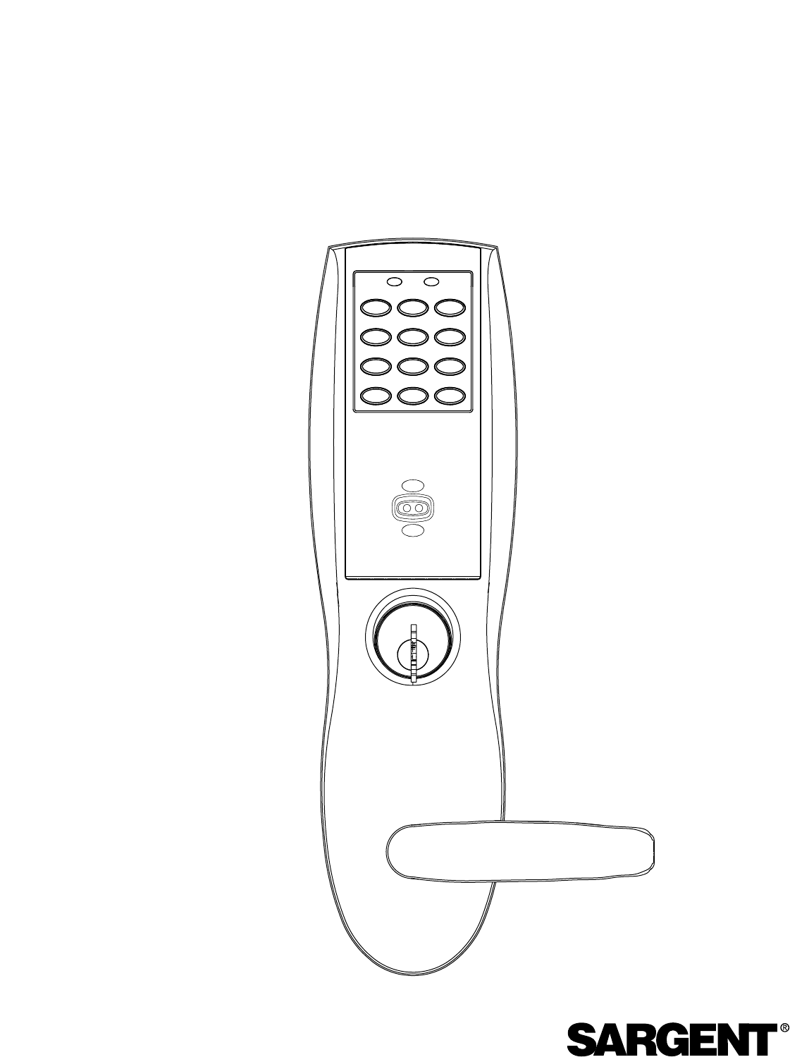
General Description
2
The SARGENT Keypad Mortise Lock/Prox is designed for areas which require authorized entry.
It is a self-contained microprocessor-controlled keypad with non volatile solid-state memory. The
keypad will hold a total of 100(LK) / 500(LU, PK, PA) different User Codes. User Codes “01”,
“02”, and “03” are utilized for Master Code, Emergency Code, and Supervisory Code,
respectively.
This product is operated by six (6) “AA” Duracell Alkaline Batteries. SARGENT mortise locks are
designed with high quality components to provide the high security, performance and durability.
Warning
!
To comply with “Fire Listed” doors, the batteries must be replaced with Alkaline batteries only.
3
Parts Breakdown
4
11
11
27/28
29
5
4
3
7
2
16
17 15
14
8915
31
21
22 20
20
18/19
25
23
24
26
21
22
26
16
1
17
30
13
13
12
24
’A’ DESIGN
(LH) ’A’ DESIGN
(RH) ’B’ DESIGN
’E’ DESIGN ’F’ DESIGN ’H’ DESIGN ’J’ DESIGN ’L’ DESIGN ’P’ DESIGN ’W’ DESIGN
33

4
Item # Part# Description # Required
1 82-3846 Outside Escutcheon with Cylinder Hole and Key Pad, or Key Pad / Prox 1
82-3847 Outside Escutcheon without Cylinder Hole and Key Pad or Key Pad / Prox 1
82-3848 Outside Escutcheon with Cylinder Hole and Prox Only 1
82-3849 Outside Escutcheon without Cylinder Hole and Prox Only 1
82-0493 Outside Escutcheon Housing Only with Cylinder Hole 1
82-0495 Outside Escutcheon Housing Only without Cylinder Hole 1
52-2431 Proximity Circuit Board and Harness Assembly 1
52-2432 Key Pad / Proximity Circuit Board and Harness Assembly 1
2 82-3837 Inside Escutcheon with Thumb Turn and 100 User Controller 1
82-3838 Inside Escutcheon without Thumb Turn and 100 User Controller 1
82-3839 Inside Escutcheon with Thumb Turn and 500 User Controller 1
82-3840 Inside Escutcheon without Thumb Turn and 500 User Controller 1
82-3841 Inside Escutcheon with Thumb Turn Prox / Key Pad Controller 1
82-3842 Inside Escutcheon without Thumb Turn Prox / Key Pad Cont. 1
82-0492 Inside Escutcheon Housing Only without Thumb Turn 1
82-0494 Inside Escutcheon Housing Only with Thumb Turn 1
52-2440 100 (LK) User Key Pad Controller Assembly 1
52-2447 500 (LU, PK) User Key Pad Controller Assembly 1
52-2454 Key Pad / Proximity (PK), Proximity Only (PA) Controller Assembly 1
3 52-2437 Battery Cover Assembly 1
4 01-1212 Security Screw 1
5 01-0297 Security Tool 1
7 82-0507 Thumb Turn 1
8 77-0772 Spindle (Thumb Turn) 1
9 01-0844 Washer (Thumb Turn) 1
10 01-0543 Spring Grip Fastener (Thumb Turn) 1
11 77-0168 Thru Bolts #8-32 x 1 7/8” Flat Head Screw 2
12 52-0033 Fire Stop Plate 1
13 01-1500 Fire Stop Screws #8 x 1/2” Type “AB” Phillips Pan Head Self Tap 2
14 82-3088 Inside Spindle Adapter & Plate Assembly 1
15 01-1495 Screw #8-32 x 1/2”2
16 82-0368 Inside Spindle / Outside Spindle 2
17 82-0347 Inside Spring / Outside Spring 2
18 82-0081 Face Plate no Dead Bolt 1
19 82-0084 Face Plate with Dead Bolt 1
20 01-1028 Face Plate Screws Machine 8-32 x 1/4”2
21 01-2299 Lock Body Screws / Wood Door #12 x 1 1/4”2
22 01-1019 Lock Body Screws / Metal Door 12-24 x 1/2”2
23 82-0184 Cap Nut 1
24 01-0079 Washer 2
25 82-3082 Plate Assembly 1
26 81-0723 Post 2
27 01-1472 Lever Handle Screw, A, E & F Lever 1
28 01-1174 Lever Handle Screw, B, J, L, P & W Lever 1
29 81-0467 Inside Lever (L.H.) "A" Design 1
81-0468 Inside Lever (R.H.) "A" Design 1
81-0490 Inside Lever "B" Design 1
81-0470 Inside Lever "E" Design 1
81-0471 Inside Lever "F" Design 1
81-0447 Inside Lever "J" Design 1
81-0489 Inside Lever "L" Design 1
81-0513 Inside Lever "P" Design 1
81-0445 Inside Lever "W" Design 1
Parts Breakdown (Continued)

5
5Features
•Non volatile memory
•Motor driven, battery operated mortise lock
•Battery operated with 6 each “AA” Alkaline
•Low battery alert–4 chirps after code entry
•External remote “request to exit” connector
•Supervisory code will unlock door when low
battery had expired
•100 (LK) or 500 (LU, PK, PA) users total
•Programming done at keypad or with
Soflink™Plus software and a PC
(LU, PA, PK). Soflink™Plus Software User
Manual A7462
•Proximity FOB or Card optional
•Operates utilizing any two to six digits per
code. Digits may be repeated and codes may
start with zero
•Cylinder override optional
•Entry of three wrong User Codes disables
all codes for ten seconds. Yellow LED
on solid
•Piezo horn can be heard with each keystroke
or turned off by Master or Supervisory Code
•Last 15 (LK) transactions can be output to
portable printer via infrared link
•Last 1000 (LU, PK, PA) transactions can be
output to portable printer via infrared link or
PC via Soflink™Plus software
•Deadbolt switch inside mortise lock allows
Emergency Code and Master Code holders
to gain entry when deadbolt is thrown
Item # Part# Description # Required
30 82-0151 O/S Lever Handle R.H. "A" Design 1
82-3074 O/S Lever Handle R.H. "A" Design Stainless Steel 1
82-0152 O/S Lever Handle L.H. "A" Design 1
82-3073 O/S Lever Handle L.H. "A" Design Stainless Steel 1
82-0153 O/S Lever Handle "B" Design 1
82-0154 O/S Lever Handle "E" Design 1
82-3074 O/S Lever Handle "E" Design Stainless Steel 1
82-0155 O/S Lever Handle "F" Design 1
82-3076 O/S Lever Handle "F" Design Stainless Steel 1
82-3079 O/S Lever Handle "H" Design 1
82-0156 O/S Lever Handle "J" Design 1
82-0157 O/S Lever Handle "L" Design 1
82-0158 O/S Lever Handle "P" Design 1
82-0159 O/S Lever Handle "W" Design 1
31 82-3732 Lockbody Assembly (with deadbolt) (8276 & 8277) 1
82-3733 Lockbody Assembly (without deadbolt) (8278 & 8279) 1
32 01-0803 Battery Alkaline ("AA" cell) 6
33 52-0253 Battery Keeper 1
Parts Breakdown (Continued)
6
Installation Instructions
6
Left Hand
Hinges Left.
Open inward.
"LH"
Left Hand
Reverse Bevel
Hinges Left.
Open Outward
"LHRB"
Right Hand
Hinges Right
Open Inward.
"RH"
Right Hand
Reverse Bevel
Hinges Right.
Open Outward.
"RHRB"
• View lock body from top and from
the outside (as shown above)
Bevel
Latchbolt Right Hand Right Hand
Reverse Bevel
Left Hand
Reverse Bevel
Lock Body
• Verify hand and bevel of door
Connector and Wires
Deadbolt
Guardbolt
Latchbolt
Front
Top
Lock w/cylinder
Override
(Shown)
End Cap
7
Outside of
Door
Inside of
Door
Outside
Cylinder Hole
Lever Handle Hole
Mortised
area
Pre-drilled and /or
Tapped Holes 2 places
Thrubolt hole
Thrubolt hole
Inside
Cylinder
Hole
Lever
Handle Hole
Thumb Turn
Lever Hole
NOTE: Always consult the proper template prior to drilling any holes.
Hole for ribbon
cable from
controller to
keypad
Installation Instructions (Continued)
Door Preparation
8
Installation Instructions (Continued)
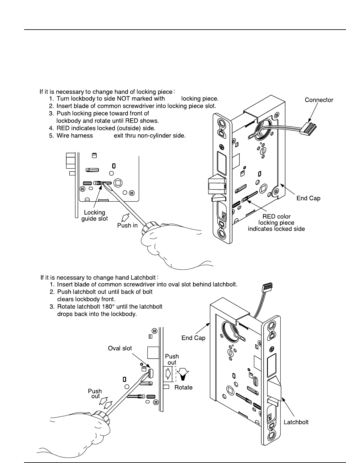
How to Reverse Lock Hand
RED
MUST
Right Hand
Shown
Outside of
Door
9
Installation Instructions (Continued)
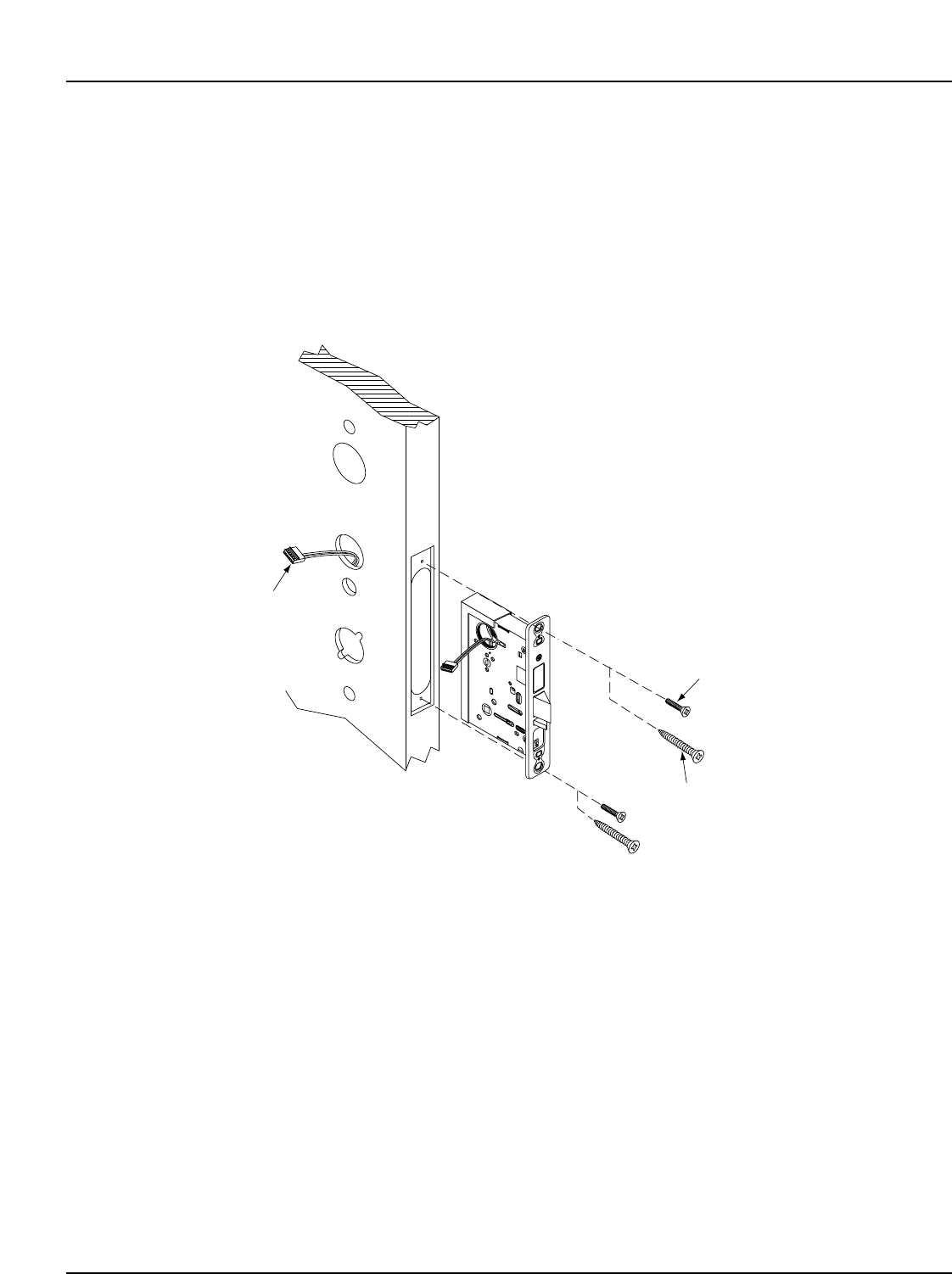
Step #1 Installation of Lockbody/Attaching Lockbody Screws
Inside of
Door
(2) #12-24 x 1/2" long
Flat Head Screw
for metal doors
(2) #12 x 1 1/4" long
Flat Head Wood Screw
for wood doors
• Wires and Connector go into the mortised
area and out of the inside cylinder hole
• Insert Lockbody in mortised cutout
• Hold loosely in place with (2) Lockbody screws
• DO NOT TIGHTEN SCREWS AT THIS TIME
MUST feed
Connector
& Wires thru
non-cylinder
side.
10
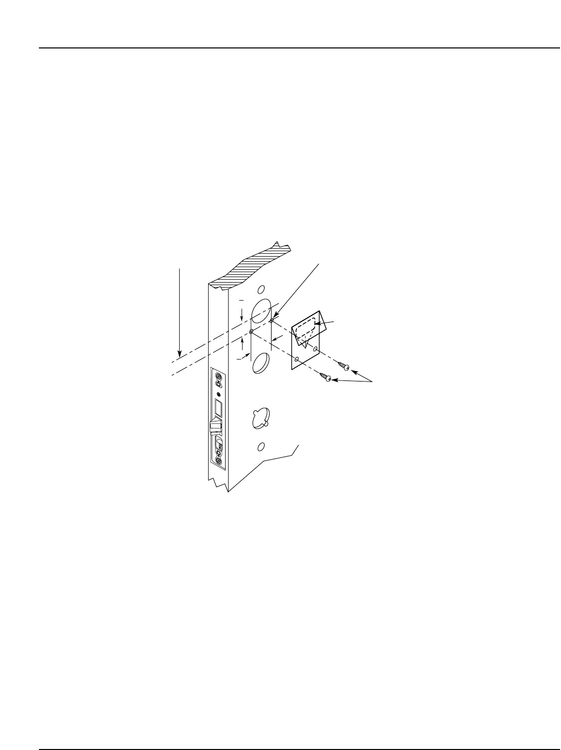
Installation Instructions (Continued)
Step #2 Attaching of Fire Stop Plate
Outside of
Door
C
L Of 1 1/2" Dia
(2) Self Tapping
Screws #8 x 1/2"
long for wood
& metal doors
(2) 1/8" Dia holes required
7"
8
1"
2
Slot
1
NOTE: Fire stop plate is required
on all fire rated doors
11
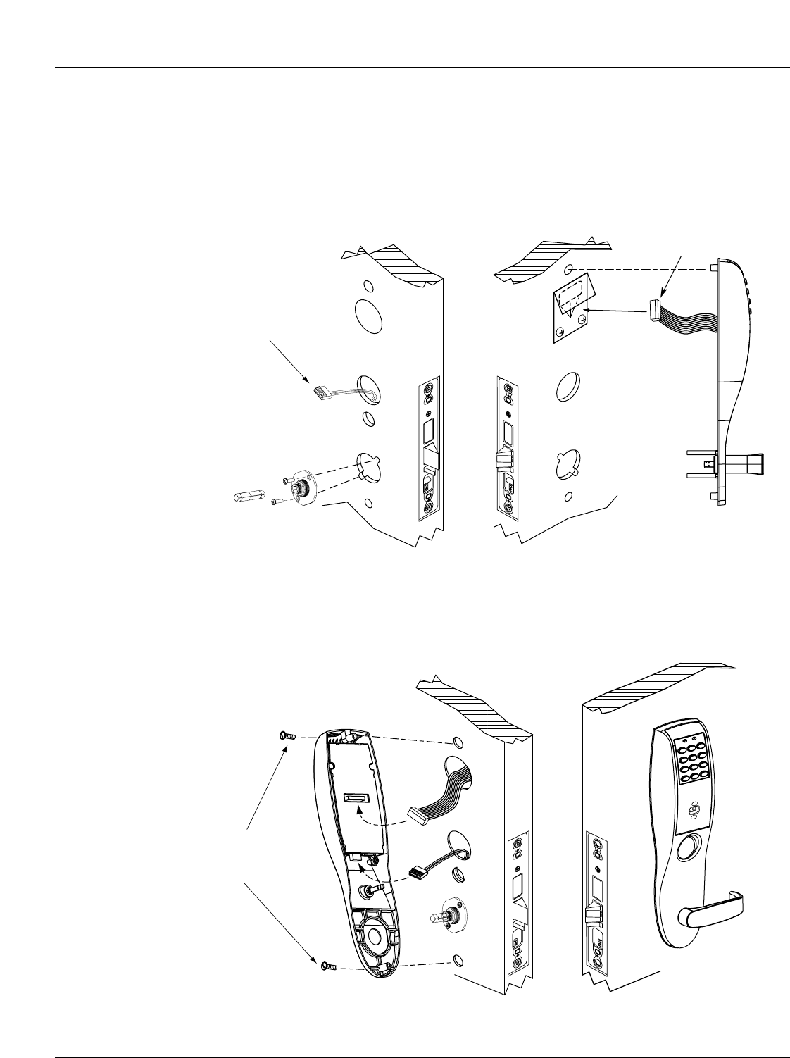
Outside of
Door
Mortise lockbody
connector and wire
*8-32
Flat Head
Screw
Keypad/prox connector
and cable
From the outside of the door, feed wires and
connector through fire stop plate
To secure the adapter and plate
assembly to the inside of the door,
thread the screws mounting posts
of the outside lever assembly.
Tighten retaining nut by hand.
Back off retaining nut slightly
until star pattern lines up with
square lever assembly corners
Insert Spindle into square
hole on inside
of door.
With outside lever horizontal, carefully insert the mounting
posts through the door and lockbody. Make sure the spindle
is properly engaged in the lock.
NOTE: For installation of optional gasket
Part #82-0500 see Gasket Installation
Locate (2) #8-32 Flat Head Screw and insert through the
escutcheon into the outside escutcheon. Tighten firmly.
Plug Keypad Connector
into inside Escutcheon
as shown. Place excessive
wire in hole.
Plug smaller Connector
as shown into the inside
Escutcheon. Place
excessive wire in inside
escutcheon assembly.
Keep excessive wires
away from cylinder hole.
NOTE:
Both connectors go on
only one way. Do not
offset the connectors.
Be sure connectors are
seated completely.
If not seated, Keypad
will not function properly.
Installation Instructions (Continued)
Step #3 Installation of Outside/Inside Escutcheon & Lever Assembly
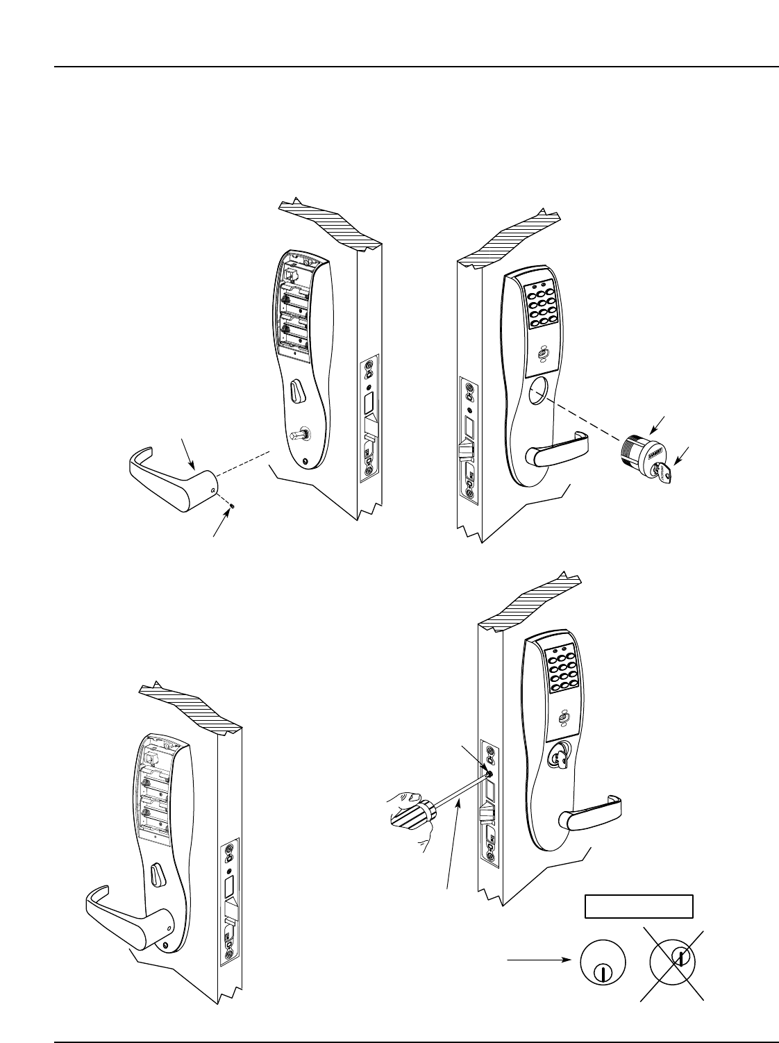
12
Installation Instructions (Continued)
Step #4 Installation of Inside Lever/Outside Cylinder
SARGENT
SARGENT
Note: Key and the
cylinder must be
rotated as shown
Correct Wrong
Very Important
•Slide lever handle onto spindle until fully seated.
Be sure handle is horizontal and facing to the rear of door
•Tighten the set screw securely with
1/8" hex wrench
•Put the turn lever
in the up position
•Align cylinder
•Screw cylinder
lockbody unit
•Tighten the set
screw to prevent
unscrewing of the
cylinder
•Turn the key way in
the cylinder to make
certain that the locking
or latching mechanism
function correclly.
Outside of Door
Type 43 Mortise
Cylinder ONLY
Key
Inside of
Door
•
Set
Screw
Inside Lever
Phillips
screwdriver
Set screw