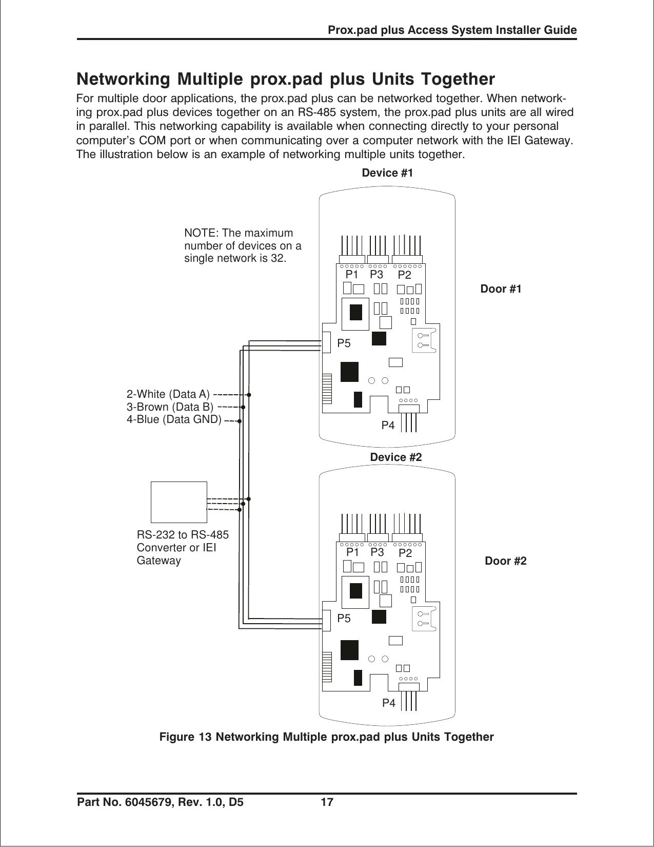
Electronics PPP ProxPad Plus User Manual quickref chp Corel VENTURA

International Electronics Inc. ProxPad Plus quickref chp Corel VENTURA

Users Manual

Access system programming - System Requirements•Hub Manager ProfessionalTM access control software version 5 or higher (part numberHUBSWR includes software installation instructions)PC Hardware Requirements•IBM-compatible Pentium-class computer•30MB available hard disk space•VGA monitor or better, 800 x 600 resolution recommended•CD-ROM or DVD-ROM drive•MouseOperating System List•Windows 98; Windows 2000; Windows XPTechnical SupportService Company: To contact IEI’s Technical Support department, call 1-800-343-9502between 8:00 a.m. - 7:00 p.m. (Eastern Standard Time), Mondaythrough Friday. Questions can also be submitted through our websiteat www.ieib.com.End User: Contact your service company.Prox.pad plus Access System Installer Guide2 Part No. 6045679, Rev. 1.0, D5
DescriptionThe prox.pad plus unit is a single door access system that is programmed and managedfrom a personal computer using Hub Manager Professional software (version 5 or higher).The prox.pad plus unit is equipped with RS-485 communications which allow up to 32prox.pad plus doors to be networked together. Connectivity options include direct connectionto a personal computer (PC) com port using the IEI 232 to 485 converter as well as LAN/WANconnectivity using the network gateway for IEI access systems.Theprox.padplusunitisuniqueinthatnoseparatecontrollerisneededandthereisnoneedto run cables from a reader to a control. The unit is self-contained and includes built in HIDproximity and IEI keypad readers as well as the controller.Separate options include the prox.pad plus power supply, which provides additional securitywith a tamper circuit that prevents lock release should the case be pried open. In addition,the prox.pad plus unit can be programmed manually with the unit's keypad.Important features include:•Managed with Hub Manager™ Professional access software•32 doors per site•No separate control to install•Eliminate costly reader wiring•2000 users per door•2000 event audit trail•Integrated-HID proximity•Card, code, card and/or code•Locate proximity 10 ft from control•Indoor and outdoor•Glass mount kit•RS-485 network•LAN/WAN connectivity option•Option for data collection with PDA•Door monitor•Main relay for lock•Programmable auxiliary relay•Local sounder for alertsProx.pad plus Access System Installer GuidePart No. 6045679, Rev. 1.0, D5 3
NOTE: prox.pad plus RS 485 communications--Theprox.padplusunitcommunicateswiththe host computer via the IEI RS232-RS485 interface (part number IEI232-485). For additionaldetails see pages 16 and 17. For wire specifications, see page 23.NOTE: Use with IEI Secured Series™ (Hub, Hub Max, Hub MiniMax) Networks--The RS485 network characteristics for the prox.pad plus unit are different than those of IEI's SecuredSeries access systems. This means the prox.pad plus unit can operate in the same systemas Secured Series controllers but not on the same physical network. Hub Manager Profes-sional software (v5 or higher) can manage Secured Series doors and prox.pad plus doors(and LS doors as well), but these door controllers cannot be “connected” to the samenetwork and network wires. Secured Series communication is RS-232; prox.pad pluscommunication is RS-485. These communication protocols are different. However, the abilityof the Hub Manager Professional software to set up multiple local and LAN/WAN sites makesthis an advantage rather than a problem.Prox.pad plus Access System Installer Guide4 Part No. 6045679, Rev. 1.0, D5
prox.pad plus Wiring Connection OverviewFigure 1 below illustrates the Pin connectors on the prox.pad plus main circuit board; the ta-ble on page 7 describes the four Pin connectors (P1, P2, P4, and P5) in detail. Specifica-tions are listed on page 23.P5 NOTE: P3 Not Used1-Blue (Terminator)2-Brown (Data A)3-White (Data B)4-Green (Data GND)System Power: 12VDCConnections for remoteinstallation of proximityantennaFor RS-485Communications1-Gray (Main Relay N/C)2-Green (Main Relay N/C)3-Blue (Main Relay C)4-Black (-V)5-Red (+V1-Green (Aux Relay N/O)2-Gray (Aux Relay N/C)3-Blue (Aux Relay C)4-Brown (REX Loop)5-Orange (Door Loop)6-White (Loop Common)1-Red (Bi Color LED)2-Black (Bi Color LED)3-White (Antenna +)4-White (Antenna -))Figure 1 Identifying Pin ConnectorsProx.pad plus Access System Installer GuidePart No. 6045679, Rev. 1.0, D5 5
IEI-Supplied Parts/Optional ItemsQuantity Description1Keypad/control unit assembly, with Prox Sensor, Backplate, hexsocket screw1 Filler Piece/REX Button1PresstoExitLabel4WallAnchors4MountingScrews1 Antenna Backplate for remote mounting1 Silicone Rubber “dogbone”4 Self-Adhering Pads (for glass mounting)1 Installer Guide4 Cable Assemblies1TamperScrewOptional Items1 Replacement Battery: Panasonic BR1225 or equivalentlots of 25 only ProxKey Keytags (IEI part number 0297301)lots of 25 only ProxCard II Cards (IEI part number 0297401)1HubManagerTM Professional PC software (version 5 or higher)1 IEI Data Collection Device (DCD) PDA softwareDefault SettingsParameter Default SettingMain Relay Lock OutputAuxiliary Relay Alarm shunt functionAudio Alert #1 Forced DoorAudio Alert #2 Propped DoorMaster Code (user one) 1234*Main Relay energizes for Five (5) secondsAudible Keypress Feedback ONPropped Door Output activates after Thirty (30) secondsForced Door Output activates for Ten (10) secondsProx.pad plus Access System Installer Guide6 Part No. 6045679, Rev. 1.0, D5
prox.pad plus Pin ConnectorsPin Connector (on maincircuit board) Description/UseP1 (5-pin connector, topleft-most location)Pin Wire Color Use1 GRAY Main Relay, Normally Closed (N.C.)2 GREEN Main Relay, Normally Open (N.O.)3 BLUE Main Relay, Common4 BLACK Ground5RED PowerIn,+12VDCP2 (6-pin connector, topright-most location)Pin Wire Color Use1GREENAuxRelayN.O.2 GRAY Aux Relay N.C.3 BLUE Aux Relay Common4 BROWN REX Loop (if used) (NO contact)5 ORANGE Door Loop Contact (NC contact)6 WHITE Loop Common (shared by REXand door loop)NOTE: Pins 1 and 2 can be wired at the installer’s optionfor one of the following alarm outputs, Alarm Shunt, ForcedDoor, or Propped Door. Mandatory: If you do not wish toinstall door contacts per Figure 7, twist the white andorange wires together. If not done, REX input will notwork.P4 (4-pin connector, bottomlocation)Pin Wire Color Use1 RED Bi-Color LED (Red +)2 BLACK Bi-Color LED (Green +)3 WHITE Antenna (+)4 WHITE Antenna (-)P-5 (4-pin connector,left-hand side location)Pin Wire Color Use1Blue Terminator2Brown DataA3White DataB4Green DataGNDProx.pad plus Access System Installer GuidePart No. 6045679, Rev. 1.0, D5 7
Performing a Secure Installation(keypad/controller away from antenna)In this configuration, the prox.pad plus keypad/controller antenna housing is removed fromthe keypad/controller and located a maximum of 10 feet away. The controller/keypad islocated inside a secure area.1. Remove the antenna from the prox.pad plus keypad/controller as described below:•Disconnect the backplate of the prox.pad plus unit from the front keypad/controller.•When handling the main printed circuit board, to guard against possible staticdischarges, touch a grounded object BEFORE touching the prox.pad plus unit.Remove the main printed circuit board by pressing the two spring tabs in the direc-tionofthearrowsasshowninFigure3.Becarefulwiththewires.•Pull up the main circuit board and remove Pin connector P4 (a 4-pin connector)from the bottom of the main board. A ribbon cable now holds the main board to thekeypad board. DO NOT pull this ribbon cable out of its connector! Once themain board is removed, you can access the interior of the antenna.•Remove the antenna housing from the keypad/controller by pressing the labeledfour secure tabs inward until the sensor housing “pops out.”2. Prepare the wiring and extension wiring as follows:•Cut off the plastic end of the prox.pad plus sensor housing harness.•Splice the recommended remote antenna cable Alpha 1174C (22AWG), 10-foot maxi-mum length, to the properly cut antenna cable using standard electrical techniques.KEYPAD/CONTROLLERFigure 2 Performing a Secure InstallationProx.pad plus Access System Installer Guide8 Part No. 6045679, Rev. 1.0, D5
3. Mount the antenna backplate in a vertical orientation and secure it to the wall throughthe two screw holes using two IEI-provided screws. Ensure that the two “weep holes”(drainage holes), provided to remove possible moisture, are positioned on the bottom.Pull the antenna wire through the wiring exits in the antenna backplate as required.(Four external cut-outs on the antenna backplate match the four spring-loaded tabs onthe antenna.)NOTE: Two side cut-outs are furnished on the antenna backplate for the wiring, ifthe installation does not permit the wiring to run through the wall. These must be“cut out” to be used.•Once the antenna backplate is mounted properly, align the antenna to the backplateand connect the antenna to the antenna backplate. The large tab in the center of theantenna assembly must be broken off before being attached to the antenna back-plate.4. Run the antenna wiring back to the secure keypad/controller and connect it to themain circuit board, using the 10-inch 4-wire harness (red, black, white, and white)that you plug into connector P4 on the controller board. Connect the red wire of theantenna to the red wire of the P4 harness, etc. Seal the wire holes with silicone.5. Select “Filler” or “Request to Exit” (REX) operation as follows:•If you elect to use the filler piece as a REX switch, return to the keypad/controller andbreak off two tabs on the filler piece as illustrated in Figure 2. The filler piece replacesthe antenna on the front of the keypad/controller for secure installations.•If the filler piece is not be be used as a REX switch, DO NOT remove the twotabs.•Select “Filler or “REX” operation and affix the appropriate IEI-provided label to thefiller piece.ForFilleroperation,notabsarebrokenoffthefillerpiece, which merely sits in placeof the remotely located antenna, once the main circuit board and cabling are re-placed.For REX operation, break off the labeled tabs, which allows a spring-loaded tab toengage the REX switch on the main circuit board and open the door.•Replace the main circuit board into the keypad/controller and Pin connector P4 to themain circuit board.•Connect the front keypad/controller of the unit to the back housing.•Secure with a hex socket screw using the supplied hex wrench, or secure with atamper screw (optional tool required).Prox.pad plus Access System Installer GuidePart No. 6045679, Rev. 1.0, D5 9
Removing/Inserting Circuit BoardsIf it proves necessary to remove or insert the main circuit board from/into the prox.pad pluscontroller/keypad, follow the steps below.1. Disconnect the back housing of the prox.pad plus unit from the frontkeypad/controller.2. (When handling the main printed circuit board, to guard against possible staticdischarges, touch a grounded object BEFORE touching the prox.pad plus unit.)Remove the main printed circuit board by pressing the two spring tabs in the directionofthearrowsasshowninFigure3.Becarefulwiththewires.3. Fold up the main circuit board and remove the P4 connector (a 4-conductor harness)from the bottom of the board.4. To re-insert, replace the main circuit board into the keypad/controller and the P4connector to the main circuit board.5. Connect the keypad/controller to the back housing.Figure 3 Removing/Inserting Printed Circuit BoardProx.pad plus Access System Installer Guide10 Part No. 6045679, Rev. 1.0, D5
P5ORANGEWHITEDOORCONTACT(Normally Closed)Figure 4 Wiring the Door Contact InputP5TO ALARM PANELDOORCONTACTGOING BACKTO ALARMPANELTO ALARM PANELGREEN(N/O)BLUE ( C )ORANGEWHITEDEDICATED DOORCONTACT (NC) BEINGMONITORED BY THEprox.pad unitFigure 5 Wiring the Aux Relay for Alarm Shunt RelayProx.pad plus Access System Installer GuidePart No. 6045679, Rev. 1.0, D5 11
BLUE(C)ORANGEWHITEP5DEDICATED DOORCONTACT (NC) BEINGMONITORED BY THEprox.pad unitTO POWER SUPPLYV- V+GREEN(NO)Figure 6 Wiring the Aux Relay for Forced Door AlarmBLUE(C)ORANGEWHITEP5DEDICATED DOORCONTACT (NC) BEINGMONITORED BY THEprox.pad unitTO POWER SUPPLYV- V+GREEN(NO)Figure 7 Wiring the Aux Relay for Propped Door AlarmProx.pad plus Access System Installer Guide12 Part No. 6045679, Rev. 1.0, D5
Wiring the REX Switch (Request to Exit)The prox.pad plus unit can be wired to monitor a remote switching device, which is intendedto be installed on the “safe” side of a door. The Request to Exit (REX) switch is a momentaryinput closure that engages the main relay forthesamelengthoftimeforwhichthemainrelay is programmed. This feature can be stored in the Transaction Log for viewing.If you elect to perform a secure installation where the controller is mounted on the secureside of the door, you can use the filler piece as a REX switch.Other REX devices can be used to include a remote button placed at a receptionist’s desk,a press-to-exit switch on the inside of a door, or a passive infrared detector, allowing free andconvenientegress.TheREXfeaturerequiresnoprogramming;simplywiretheunitasillus-trated in Figure 8. To incorporate this feature, follow the steps below:1. Turn OFF power to the prox.pad plus unit, and then remove the front keypad/controllerfrom the backplate.2. Locate connector P2 on the main circuit board.3. Plug the 6-conductor harness into connector P2. (The 2-pin jumper on pins 5 and 6of connector P2 must be removed first.)4. If you do not wish to install the door contacts per Figure 8, twist the white wireand the orange wires together; this is mandatory. If this is not done, the REXinput will not function.NOTE: The door contact MUST be closed for the REX feature to work properly.P5 P5(Normally Closed)Figure 8 Wiring the REX SwitchProx.pad plus Access System Installer GuidePart No. 6045679, Rev. 1.0, D5 13
Wiring the Main RelayThe door lock is wired to connector P1 on the prox.pad plus main circuit board.Wiring for this 5-pin connector is described in the first table on page 7. Figure 9 provides anElectric Strike (Fail Secure) wiring diagram, Figure 10 a MagLock (Fail Safe) wiring diagram.Power for the prox.pad plus unit must be from a minimum 10-15 volt DC linear, filtered andregulated power supply. It is typical for the chosen power supply to power BOTH theprox.pad plus unit and the selected locking device. When using one power supply for boththe prox.pad plus unit and locking device, be sure to include both devices in your currentrequirements calculations.NOTE: IEI recommends that you ground the power supply to earth ground.P5Figure 9 Electric Strike (Fail Secure Wiring Diagram)Prox.pad plus Access System Installer Guide14 Part No. 6045679, Rev. 1.0, D5
BLACK(V-) BLUE(MAIN RELAY C)V-V+MAGLOCK(FAIL SAFE) POWERSUPPLYGRAY(MAIN RELAY N/C) RED(V + IN)P5P4P1 P2P3Figure 10 MagLock (Fail Safe) Wiring DiagramProx.pad plus Access System Installer GuidePart No. 6045679, Rev. 1.0, D5 15
prox.pad plus CommunicationsThe prox.pad plus is equipped with RS-485 communications with a data rate of 19200bits/sec. This allows you to connect the unit to a personal computer (PC) either via the com-puter’s COM (serial) port or over a computer network to manage the system using Hub Man-agerTM Professional (v 5 or higher) software. To connect the prox.pad plus unit to a computerCOM port (which is RS-232), an RS-232 to RS-485 converter is required. To connect theprox.pad plus unit via a computer network, the IEI Gateway device is required. The maximumdistance from the RS-485 device is 4000 feet using the specified cable. The illustrationsbelow show examples of both connection types. Please see the instructions for your RS-232toRS-485converterortheinstructionsfortheIEIGatewayfordetailsaboutthosedevices.Also, refer to the EIA RS-485 specifications for further details.RS-232 RS-485RS-232 to RS-485ConverterTo PCCOM port ó2-Brown (Data A)3-White (Data B)4-Green (Data GND)NOTE: The Terminator wiremay not be required.P1 P3 P2P5P4Figure 11 Connecting the prox.pad plus to a PC COM PortRS-485óTo ComputerNetwork2-Brown (Data A)3-White (Data B)4-Green (Data GND) P1 P3 P2P5P4IEI GatewayFigure 12 Connecting the prox.pad plus to a NetworkProx.pad plus Access System Installer Guide16 Part No. 6045679, Rev. 1.0, D5
Networking Multiple prox.pad plus Units TogetherFor multiple door applications, the prox.pad plus can be networked together. When network-ing prox.pad plus devices together on an RS-485 system, the prox.pad plus units are all wiredin parallel. This networking capability is available when connecting directly to your personalcomputer’s COM port or when communicating over a computer network with the IEI Gateway.The illustration below is an example of networking multiple units together.Device #1Device #2Door #1Door #2NOTE: The maximumnumber of devices on asingle network is 32.RS-232 to RS-485Converter or IEIGateway2-White (Data A)3-Brown (Data B)4-Blue (Data GND)P5P1 P3 P2P1 P3 P2P5P4P4Figure 13 Networking Multiple prox.pad plus Units TogetherProx.pad plus Access System Installer GuidePart No. 6045679, Rev. 1.0, D5 17
Program CommandsIn addition to personal computer (PC) programming, the prox.pad plus unit can beprogrammed manually using the keypad on each unit and without the use of a personalcomputer and software. Keypad programming can be helpful to get a door or doors up andrunning prior to having the availability of the host computer. In all cases, the personal com-puter programming options supersede the keypad programming options.Defaults are in bold. See the prox.pad plus Installation/Programming Manual located on thesupplied CD-ROM for further details.Action Desired Press DetailsTo enter programmode 99 # (Master Code) *Default Master code =1234.Yellow LED blinks slowly1. Change master codeCode-only operation(example, 4321 mastercode)1 # (new code) * (repeat code) *1 # 4321 * 4321 *2. Assign outputs 10 # virtual output # physical output # **Virtual Output Physical Output1-Lock 1-Relay1(Main)2 - Alarm Shunt 2 - Relay 2 (Aux)3-ProppedDoor 5-AudioAlert#14-ForcedDoor 6-AudioAlert#2Entering a zero (0) for avirtual output disablesthe physical output3. Set lock outputduration 11 # tt # 0 # * *tt = number of secondsto operate lock onaccess (1 through 255)defaults to 5 seconds4. Delete users user-location # **5. Set/clear keypadoptions 30 # option # set/clear # ** See options belowOption Set/Clear0-audio keypress feedback 0=off, 1=ON1-visual keypress feedback 0=off, 1=ON2-auto entry enable 0=OFF, 1=on3-Card and PIN required for 0=OFF,1=onProgram mode5-user lockout enable 0=off, 1=ON7-internal REX select 0=OFF,1=on8-user lockout select 0=BY LOCATION,1=by group9-timezones select 0=OFF,1=on10-holiday timezone midnight 0=off, 1=ONcrossing11-auto-unlock select 0=OFF,1=on12-first-in auto-unlock 0=OFF,1=on13-daylight savings time select 0=off, 1=ON15-daylight savings time format 0=USA,1=European16-anti-passback 0=off,1=ON17-user dump select 0=all users1=programmedusers onlyProx.pad plus Access System Installer Guide18 Part No. 6045679, Rev. 1.0, D5
Action Desired Press Details6a. Print programmeduser list 25#0#0#**6b. Print programmeduser list (starting at acertain user)25#0#startuser#**7. Change keypadparameters 32#parameter#value#** See options belowParameter Value0-error lockout threshold 1-50 (def=3)1-error lockout duration 1-255 (def=10 sec)3-extended unlock time 1-255 (def=10 sec)4-site ID (for cmds 51, 57) 0-255 (def=11)5-user timezone mask 0-255 (def=255)(for programming users throughthe faceplate)6-user lockout group 0-15 (def=4)7-lockout by group operand 0-3 (def=0)(see below)0=lockout users in all other groups1=lockout users in this group(except lockout users)2=lockout users in higher numberedgroups3=lockout users in lower numberedgroups8-anti-passback delay 2-240 (1/4 secondincrements, default= 4 or 1 second8. Set/clear auto-unlockmask 38 # autz # set/clear # * *autz - auto-unlocktimezone (1-8)Entering a 1 sets thetimezone asauto-unlock and a 0clears it9. Restore systemdefaults (master userand systemoptions/parameters only)40 # 00000 # 00000 # * *10. Set system time 41 # hhmm # 0 # ** hhmm=hour/minute,24-hr format11. Set system date 42 # mmddyy # dow # **mmddyy=month, date,year; dow=day ofweek,1=Sunday,etc.12. Set door number 43 # nnnnn # 0 # **nnnnn=door numberDefault=0001 (maxnumber=65535)13. Set propped dooroutput time 44#ttt#0#**ttt=propped door time,to nearest 10’sseconds, entered as00-990; default=30 secsentering 00 disablespropped doorProgram Commands (continued)Prox.pad plus Access System Installer GuidePart No. 6045679, Rev. 1.0, D5 19
Action Press Details14.Setforceddooroutput time 45#ttt#0#**ttt=forced door time, tonearest 10’s seconds,entered as 00-990 (00latches it); default=10secs15. Clear eeprommemory and restoredefault settings46 # 00000 # 00000 # ** (See page 2)User Types0-toggle code1-standard access2-Log Dump3-lockout4-extended lockout5-single use6-relock code7-emergency16a. “Code only” user 50#type#location#keypin*keypin*16b. “Card only” userby presentation 50#type#location#**<presentcard>16c. “Card AND code”user50#type#location#keypin*keypin*<present card>16d. Delete user 50#0#location#**17. Program 26-bit“card only” user withoutpresenting card51#type#location#cardpin*cardpin*Location must begreater than 2;master/supervisorcannot be set as “cardonly”18. Program “card ORcode” user52#type#location#keypin*keypin*<present card>19. Programconsecutive “card only”users by presentation53 # type # start user # ** <present card><present card> ...Startusermustbegreater than 2;master/supervisorcannot be set as “cardonly”20. Enable/disable users 56 # enable/disable # user # **0=Enablesthatuser1=Disablesthatuser;master user cannot bedisabled; anunprogrammed usercannot be enabled ordisabled (generates aprogram error)21. Program block of26-bit “card only” userswithout presenting cards57#numberofusers#startuser#cardpin*card pin *Startusermustbegreater than 2;master/supervisorcannot be set as “cardonly”; uses site ID setin command 32,parameter 4Program Commands (continued)Prox.pad plus Access System Installer Guide20 Part No. 6045679, Rev. 1.0, D5
Action Press Details22. Delete block ofconsecutive users58 # start user # start user # number of users* number of users *23. Dump transactionsto IR port 70#0#0#**This command must beused while in Programmode24. Set/clear event logmask 73#event#set/clear#**See options below; allevents are logged bydefault unless statedotherwise belowEvent1-access denied - invalid PIN2-program denied4-REX5-Propped Door6-Door Closed7ForcedDoor16-log dumped by user #N17-access granted to user #N19-access denied to user #N, bad timezone20-togglemodeactivatedbyuser#N(latch set)21 - toggle mode de-activated by user #N(latch clear)22 - 1st in auto-unlock triggered by user #N23 - door relocked by user #N24 - user lockout enabled by user #N25 - user lockout disabled by user #N26 - access denied to user #N - user isdisabled27 - card/code mismatch29 - program mode started by user #N30 - log erased by user #N32-unprogrammedcarddata33 - unprogrammed code data50 - log retrieved51 - access denied to user #N, user grouplockoutEvents 30 and 50cannot be disabledEvents 32 and 33 aredisabled by default25. Reset (erase)transaction log 76 # 00000 # 00000 # **26. To exit Programmode *(afterfinalcommand) Yellow stops flashingProgram Commands (continued)Prox.pad plus Access System Installer GuidePart No. 6045679, Rev. 1.0, D5 21
Led Indicators/Sounder OperationsLED or Sounder Visual/AudibleCondition DescriptionYellow LED Slow blink Unit is in Program modeRapid blink Verify mode is active (checking that the last twovalues in sequence match)Steady Program error; to clear, press *or error lockoutVery rapid blink Memory (eeprom) erase is in progress(commands 40/46, loop-back)Bi-color LED Steady red Lock output deenergizedSteady green Lock output is energized (timed or latched)Red/green alternating Awaiting second PIN during “Card AND Code”access attemptGreen blink Auto-unlock activeSounderShort beep(100 ms) every 2secondsAudio alert #2 is activeSounder 1/2 sec on,1/2 sec off Audio alert #1 is activeDouble beep Lockout is canceledPair of double beeps Lockout is activated3 slow beeps (250ms), then single beep Self-test is completeSounder AfterPIN/Card 1 single beep Valid card access1 long beep followedby 1 short beep User disabled1 long beep followedby 2 short beeps Bad timezone1 long beep followedby 3 short beeps User lockout3 rapid beeps aftercode entered or cardpresentedCode or Card is not found4 quick beeps First-In Auto-unlock6 quick beeps Toggle mode is activeProx.pad plus Access System Installer Guide22 Part No. 6045679, Rev. 1.0, D5
prox.pad plus SpecificationsELECTRICALPower Supply/CurrentRequirements10-15 VDC, linear filtered and regulated power supply500 mA (not including locking device or peripherals)WIRINGRemote Antenna CableALPHA 1174C (22AWG) 4-wire, stranded (this is requiredONLY if you choose to remote the antenna 10 feet awayfrom the keypad/controller)RS-485 Cable24AWG, shielded, two twisted-pair telephone cable with ashunt capacitance of 16 pF/Ft (required only when usingsoftware)Power Supply Cable 18AWG - 22AWG 2-wire stranded (depends on distance)Door Lock Cable 18AWG - 22AWG 2-wire stranded (depends on distance)Door Monitor Cable 18AWG - 22AWG 2-wire stranded (depends on distance)REX Cable (if using remote switch) 2-wire strandedMECHANICALHeight 5.25 in (13.3 cm)Width 2.75 in (7 cm)Depth 1.375 in (3.5 cm)RELAY OUTPUTSMain Relay - Form C (switches up to 2A)Aux Relay - Form C (switches up to 2A)MONITOR INPUTSDoor Position (Normally Closed, dry contact)Request to Exit (REX, Normally Open, dry contact)OTHER OUTPUTSInfrared output to optional PDA program (38400 bits/sec)SOUNDER 4000 Hz, defeatableLEDs Bi-Color (red/green)YellowProx.pad plus Access System Installer GuidePart No. 6045679, Rev. 1.0, D5 23
COMPATIBLE PROXIMITYCARDSAll 26-bit HID card, including the following: ProxCard II,IsoProx II, Duo Prox II, and Proxkey FOB; 26-bit cards arerequired for manual or batch programmingUNIT CAPACITYUsers 2,000 users maximum; each user can have a card/tag, aPINcode,oracard/tagplusaPINcodeTransactions 2,000 transactions maximum; each transaction includestime, date, user “slot number,” and eventLock Time 1-255 secondsLock Mode Access Time or Toggle/LatchALARM OUTPUT One of these three events can be programmed: AlarmShunt Relay, Forced Door Relay, or Propped Door RelayUSER ACCESSCONFIGURATIONSCode ONLYCode AND CardCard ONLYCode OR CardPROGRAMMABLE USERTYPES Each user is assigned one of the following user types:0-Toggle/latch strike1-Normal access2-log Dump3-Lockout4-Extended unlock5-Single use6-Relock7-EmergencySYSTEM USES/INSTALLATIONCONFIGURATIONSSuitable for small installations or remote locations,indoors or outdoorsWall mounted, glass mounted, or secure installationENVIRONMENTAL Indoor or outdoorOperating Temperature -31° to 150° F (-35° to 66° C)Operating Humidity 5% to 95% relative humidity, non-condensingProx.pad plus Access System Installer Guide24 Part No. 6045679, Rev. 1.0, D5
This page is left blank intentionally.Prox.pad plus Access System Installer GuidePart No. 6045679, Rev. 1.0, D5 25
This page is left blank intentionally.Prox.pad plus Access System Installer Guide26 Part No. 6045679, Rev. 1.0, D5
This page is left blank intentionally.Prox.pad plus Access System Installer GuidePart No. 6045679, Rev. 1.0, D5 27
Questions or ProblemsIf you have any questions about initial prox.pad plus programming or operation, or encounterany installation problems, contact your prox.pad plus dealer or distributor. The completeInstallation/Programming Reference manual is contained on the supplied CD-ROM.International Electronics, Inc. © Copyright 2003 International Electronics, Inc.427 Turnpike Street All Rights Reserved Published in U.S.A.Canton, MA 02021 U.S.A.Telephone: 781-821-5566 (main) 800-733-9502 (sales in MA) 800-343-9502 (sales)Fax: 781-821-4443 Fax Info Ctr: 781-821-0734 Internet: www.ieb.comWarranty PolicyInternational Electronics Inc. (IEI) warrants its products to be free from defects in material andworkmanship when they have been installed in accordance with the manufacturer’s instruc-tions and have not been modified or tampered with. IEI does not assume any responsibilityfor damage or injury to person or property due to improper care, storage, handling, abuse,misuse, normal wear and tear, or an act of God.IEI’s sole responsibility is limited to the repair (at IEI’s option) or the replacement of the defec-tive product or part when sent to IEI’s facility (freight and insurance charges prepaid) after ob-taining IEI’s Return Material Authorization. IEI will not be liable to the purchaser or any oneelse for incidental or consequential damages arising from any defect in, or malfunction of, itsproducts.Except as stated above, IEI makes no warranties, either expressed or implied, as to any mat-ter whatsoever, including, and without limitation to, the condition of its products, their mer-chantability, or fitness for any particular purpose.Warranty Periods Are:1 Year PowerKey2 Years Door Gard & Secured Series Products2 Years prox.pad and prox.pad plus2 Years LS Series2 Years Glass Break5 Years ‘e’ Series Keypads2 Years Network GatewayAll products have date code labeling to determine the warranty period. A 90-day grace periodis added to all products to account for shelf life.Prox.pad plus Access System Installer Guide28 Part No. 6045679, Rev. 1.0, D5

Navigation menu