Electronics PPP ProxPad Plus User Manual quickref chp Corel VENTURA
International Electronics Inc. ProxPad Plus quickref chp Corel VENTURA
Users Manual

Access system programming - System Requirements
•Hub Manager ProfessionalTM access control software version 5 or higher (part number
HUBSWR includes software installation instructions)
PC Hardware Requirements
•IBM-compatible Pentium-class computer
•30MB available hard disk space
•VGA monitor or better, 800 x 600 resolution recommended
•CD-ROM or DVD-ROM drive
•Mouse
Operating System List
•Windows 98; Windows 2000; Windows XP
Technical Support
Service Company: To contact IEI’s Technical Support department, call 1-800-343-9502
between 8:00 a.m. - 7:00 p.m. (Eastern Standard Time), Monday
through Friday. Questions can also be submitted through our website
at www.ieib.com.
End User: Contact your service company.
Prox.pad plus Access System Installer Guide
2 Part No. 6045679, Rev. 1.0, D5

Description
The prox.pad plus unit is a single door access system that is programmed and managed
from a personal computer using Hub Manager Professional software (version 5 or higher).
The prox.pad plus unit is equipped with RS-485 communications which allow up to 32
prox.pad plus doors to be networked together. Connectivity options include direct connection
to a personal computer (PC) com port using the IEI 232 to 485 converter as well as LAN/WAN
connectivity using the network gateway for IEI access systems.
Theprox.padplusunitisuniqueinthatnoseparatecontrollerisneededandthereisnoneed
to run cables from a reader to a control. The unit is self-contained and includes built in HID
proximity and IEI keypad readers as well as the controller.
Separate options include the prox.pad plus power supply, which provides additional security
with a tamper circuit that prevents lock release should the case be pried open. In addition,
the prox.pad plus unit can be programmed manually with the unit's keypad.
Important features include:
•Managed with Hub Manager™ Professional access software
•32 doors per site
•No separate control to install
•Eliminate costly reader wiring
•2000 users per door
•2000 event audit trail
•Integrated-HID proximity
•Card, code, card and/or code
•Locate proximity 10 ft from control
•Indoor and outdoor
•Glass mount kit
•RS-485 network
•LAN/WAN connectivity option
•Option for data collection with PDA
•Door monitor
•Main relay for lock
•Programmable auxiliary relay
•Local sounder for alerts
Prox.pad plus Access System Installer Guide
Part No. 6045679, Rev. 1.0, D5 3
NOTE: prox.pad plus RS 485 communications--Theprox.padplusunitcommunicateswith
the host computer via the IEI RS232-RS485 interface (part number IEI232-485). For additional
details see pages 16 and 17. For wire specifications, see page 23.
NOTE: Use with IEI Secured Series™ (Hub, Hub Max, Hub MiniMax) Networks--The RS
485 network characteristics for the prox.pad plus unit are different than those of IEI's Secured
Series access systems. This means the prox.pad plus unit can operate in the same system
as Secured Series controllers but not on the same physical network. Hub Manager Profes-
sional software (v5 or higher) can manage Secured Series doors and prox.pad plus doors
(and LS doors as well), but these door controllers cannot be “connected” to the same
network and network wires. Secured Series communication is RS-232; prox.pad plus
communication is RS-485. These communication protocols are different. However, the ability
of the Hub Manager Professional software to set up multiple local and LAN/WAN sites makes
this an advantage rather than a problem.
Prox.pad plus Access System Installer Guide
4 Part No. 6045679, Rev. 1.0, D5
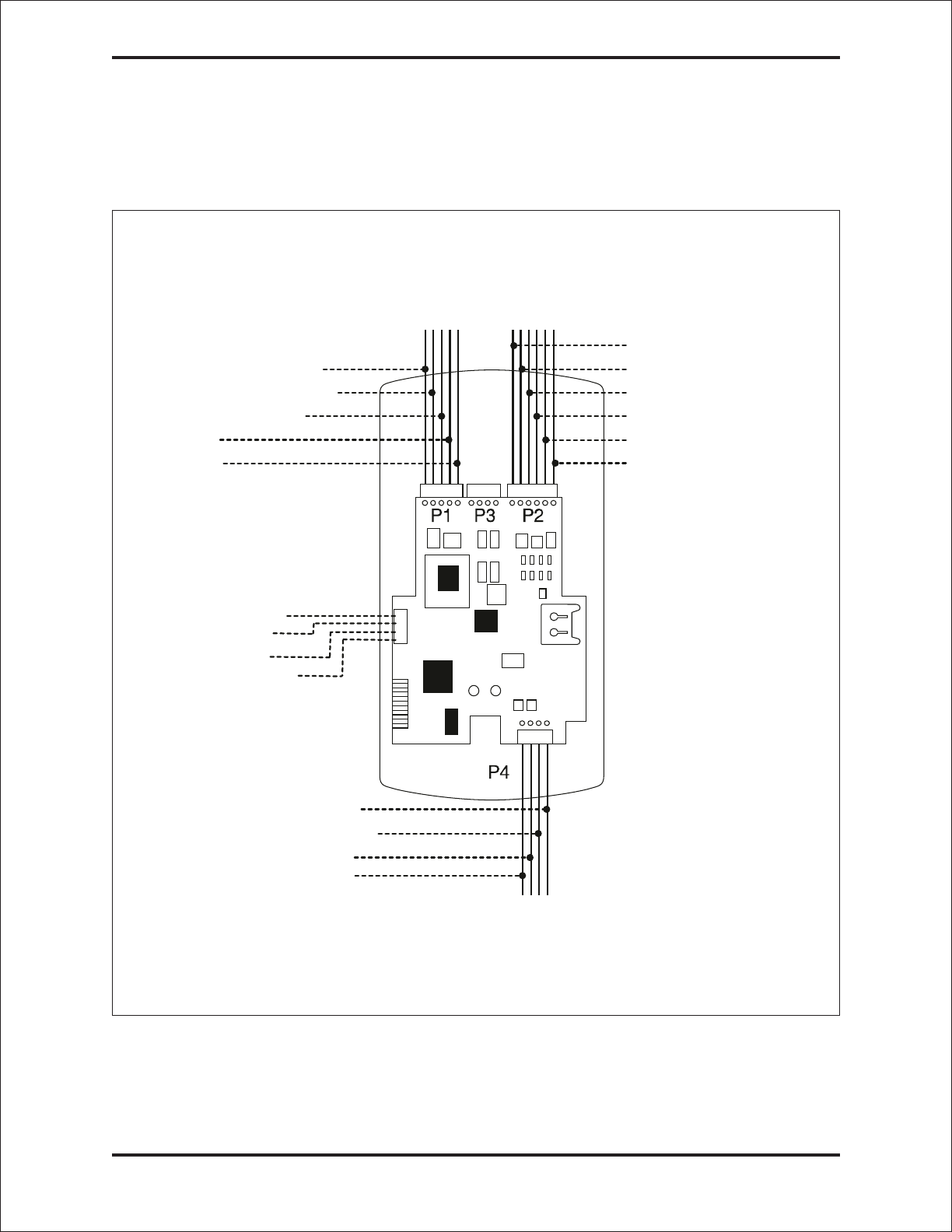
prox.pad plus Wiring Connection Overview
Figure 1 below illustrates the Pin connectors on the prox.pad plus main circuit board; the ta-
ble on page 7 describes the four Pin connectors (P1, P2, P4, and P5) in detail. Specifica-
tions are listed on page 23.
P5 NOTE: P3 Not Used
1-Blue (Terminator)
2-Brown (Data A)
3-White (Data B)
4-Green (Data GND)
S
ystem Power: 12VDC
Connections for remote
installation of proximity
antenna
F
or RS-485
C
ommunications
1
-Gray (Main Relay N/C)
2
-Green (Main Relay N/C)
3
-Blue (Main Relay C)
4
-Black (-V)
5
-Red (+V
1-Green (Aux Relay N/O
)
2-Gray (Aux Relay N/C
)
3-Blue (Aux Relay C)
4-Brown (REX Loop)
5-Orange (Door Loop)
6-White (Loop Commo
n)
1-Red (Bi Color LED)
2-Black (Bi Color LED)
3-White (Antenna +)
4-White (Antenna -)
)
Figure 1 Identifying Pin Connectors
Prox.pad plus Access System Installer Guide
Part No. 6045679, Rev. 1.0, D5 5

IEI-Supplied Parts/Optional Items
Quantity Description
1Keypad/control unit assembly, with Prox Sensor, Backplate, hex
socket screw
1 Filler Piece/REX Button
1PresstoExitLabel
4WallAnchors
4MountingScrews
1 Antenna Backplate for remote mounting
1 Silicone Rubber “dogbone”
4 Self-Adhering Pads (for glass mounting)
1 Installer Guide
4 Cable Assemblies
1TamperScrew
Optional Items
1 Replacement Battery: Panasonic BR1225 or equivalent
lots of 25 only ProxKey Keytags (IEI part number 0297301)
lots of 25 only ProxCard II Cards (IEI part number 0297401)
1HubManager
TM Professional PC software (version 5 or higher)
1 IEI Data Collection Device (DCD) PDA software
Default Settings
Parameter Default Setting
Main Relay Lock Output
Auxiliary Relay Alarm shunt function
Audio Alert #1 Forced Door
Audio Alert #2 Propped Door
Master Code (user one) 1234*
Main Relay energizes for Five (5) seconds
Audible Keypress Feedback ON
Propped Door Output activates after Thirty (30) seconds
Forced Door Output activates for Ten (10) seconds
Prox.pad plus Access System Installer Guide
6 Part No. 6045679, Rev. 1.0, D5

prox.pad plus Pin Connectors
Pin Connector (on main
circuit board) Description/Use
P1 (5-pin connector, top
left-most location)
Pin Wire Color Use
1 GRAY Main Relay, Normally Closed (N.C.)
2 GREEN Main Relay, Normally Open (N.O.)
3 BLUE Main Relay, Common
4 BLACK Ground
5RED PowerIn,+12VDC
P2 (6-pin connector, top
right-most location)
Pin Wire Color Use
1GREENAuxRelayN.O.
2 GRAY Aux Relay N.C.
3 BLUE Aux Relay Common
4 BROWN REX Loop (if used) (NO contact)
5 ORANGE Door Loop Contact (NC contact)
6 WHITE Loop Common (shared by REX
and door loop)
NOTE: Pins 1 and 2 can be wired at the installer’s option
for one of the following alarm outputs, Alarm Shunt, Forced
Door, or Propped Door. Mandatory: If you do not wish to
install door contacts per Figure 7, twist the white and
orange wires together. If not done, REX input will not
work.
P4 (4-pin connector, bottom
location)
Pin Wire Color Use
1 RED Bi-Color LED (Red +)
2 BLACK Bi-Color LED (Green +)
3 WHITE Antenna (+)
4 WHITE Antenna (-)
P-5 (4-pin connector,
left-hand side location)
Pin Wire Color Use
1Blue Terminator
2Brown DataA
3White DataB
4Green DataGND
Prox.pad plus Access System Installer Guide
Part No. 6045679, Rev. 1.0, D5 7
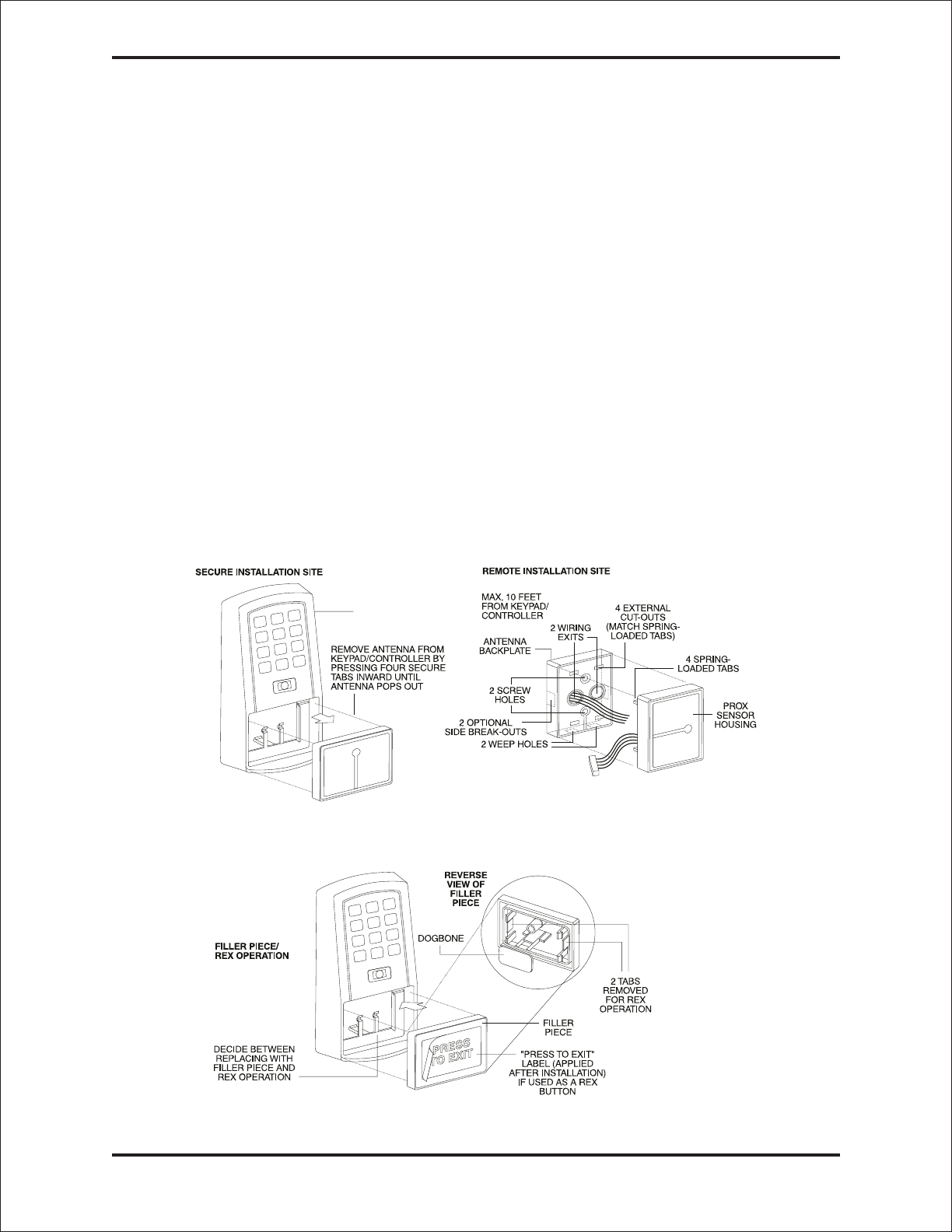
Performing a Secure Installation
(keypad/controller away from antenna)
In this configuration, the prox.pad plus keypad/controller antenna housing is removed from
the keypad/controller and located a maximum of 10 feet away. The controller/keypad is
located inside a secure area.
1. Remove the antenna from the prox.pad plus keypad/controller as described below:
•Disconnect the backplate of the prox.pad plus unit from the front keypad/controller.
•When handling the main printed circuit board, to guard against possible static
discharges, touch a grounded object BEFORE touching the prox.pad plus unit.
Remove the main printed circuit board by pressing the two spring tabs in the direc-
tionofthearrowsasshowninFigure3.Becarefulwiththewires.
•Pull up the main circuit board and remove Pin connector P4 (a 4-pin connector)
from the bottom of the main board. A ribbon cable now holds the main board to the
keypad board. DO NOT pull this ribbon cable out of its connector! Once the
main board is removed, you can access the interior of the antenna.
•Remove the antenna housing from the keypad/controller by pressing the labeled
four secure tabs inward until the sensor housing “pops out.”
2. Prepare the wiring and extension wiring as follows:
•Cut off the plastic end of the prox.pad plus sensor housing harness.
•Splice the recommended remote antenna cable Alpha 1174C (22AWG), 10-foot maxi-
mum length, to the properly cut antenna cable using standard electrical techniques.
KEYPAD/
CONTROLLER
Figure 2 Performing a Secure Installation
Prox.pad plus Access System Installer Guide
8 Part No. 6045679, Rev. 1.0, D5

3. Mount the antenna backplate in a vertical orientation and secure it to the wall through
the two screw holes using two IEI-provided screws. Ensure that the two “weep holes”
(drainage holes), provided to remove possible moisture, are positioned on the bottom.
Pull the antenna wire through the wiring exits in the antenna backplate as required.
(Four external cut-outs on the antenna backplate match the four spring-loaded tabs on
the antenna.)
NOTE: Two side cut-outs are furnished on the antenna backplate for the wiring, if
the installation does not permit the wiring to run through the wall. These must be
“cut out” to be used.
•Once the antenna backplate is mounted properly, align the antenna to the backplate
and connect the antenna to the antenna backplate. The large tab in the center of the
antenna assembly must be broken off before being attached to the antenna back-
plate.
4. Run the antenna wiring back to the secure keypad/controller and connect it to the
main circuit board, using the 10-inch 4-wire harness (red, black, white, and white)
that you plug into connector P4 on the controller board. Connect the red wire of the
antenna to the red wire of the P4 harness, etc. Seal the wire holes with silicone.
5. Select “Filler” or “Request to Exit” (REX) operation as follows:
•If you elect to use the filler piece as a REX switch, return to the keypad/controller and
break off two tabs on the filler piece as illustrated in Figure 2. The filler piece replaces
the antenna on the front of the keypad/controller for secure installations.
•If the filler piece is not be be used as a REX switch, DO NOT remove the two
tabs.
•Select “Filler or “REX” operation and affix the appropriate IEI-provided label to the
filler piece.
ForFilleroperation,notabsarebrokenoffthefillerpiece, which merely sits in place
of the remotely located antenna, once the main circuit board and cabling are re-
placed.
For REX operation, break off the labeled tabs, which allows a spring-loaded tab to
engage the REX switch on the main circuit board and open the door.
•Replace the main circuit board into the keypad/controller and Pin connector P4 to the
main circuit board.
•Connect the front keypad/controller of the unit to the back housing.
•Secure with a hex socket screw using the supplied hex wrench, or secure with a
tamper screw (optional tool required).
Prox.pad plus Access System Installer Guide
Part No. 6045679, Rev. 1.0, D5 9
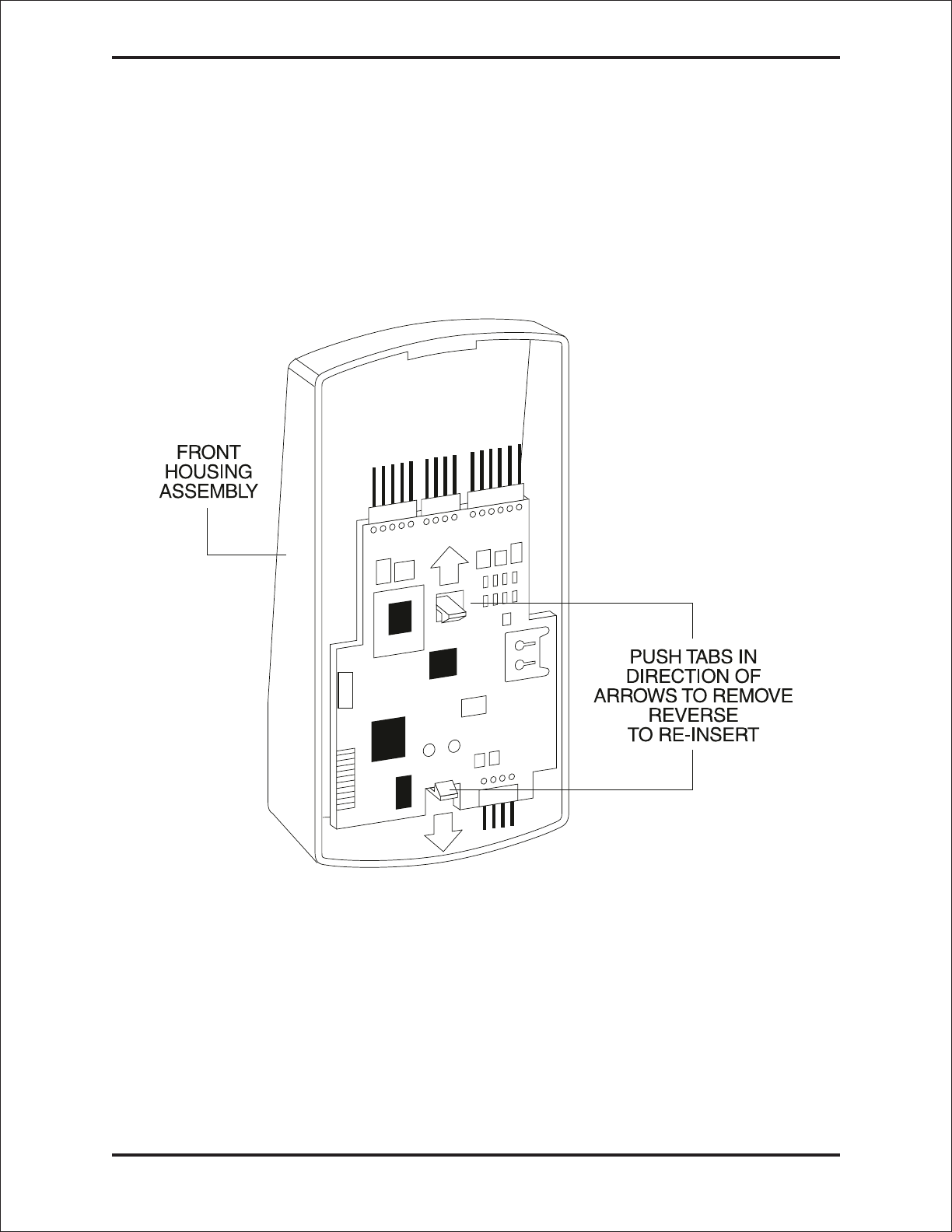
Removing/Inserting Circuit Boards
If it proves necessary to remove or insert the main circuit board from/into the prox.pad plus
controller/keypad, follow the steps below.
1. Disconnect the back housing of the prox.pad plus unit from the front
keypad/controller.
2. (When handling the main printed circuit board, to guard against possible static
discharges, touch a grounded object BEFORE touching the prox.pad plus unit.)
Remove the main printed circuit board by pressing the two spring tabs in the direction
ofthearrowsasshowninFigure3.Becarefulwiththewires.
3. Fold up the main circuit board and remove the P4 connector (a 4-conductor harness)
from the bottom of the board.
4. To re-insert, replace the main circuit board into the keypad/controller and the P4
connector to the main circuit board.
5. Connect the keypad/controller to the back housing.
Figure 3 Removing/Inserting Printed Circuit Board
Prox.pad plus Access System Installer Guide
10 Part No. 6045679, Rev. 1.0, D5
P5
ORANGE
WHITE
DOOR
CONTACT
(Normally Closed)
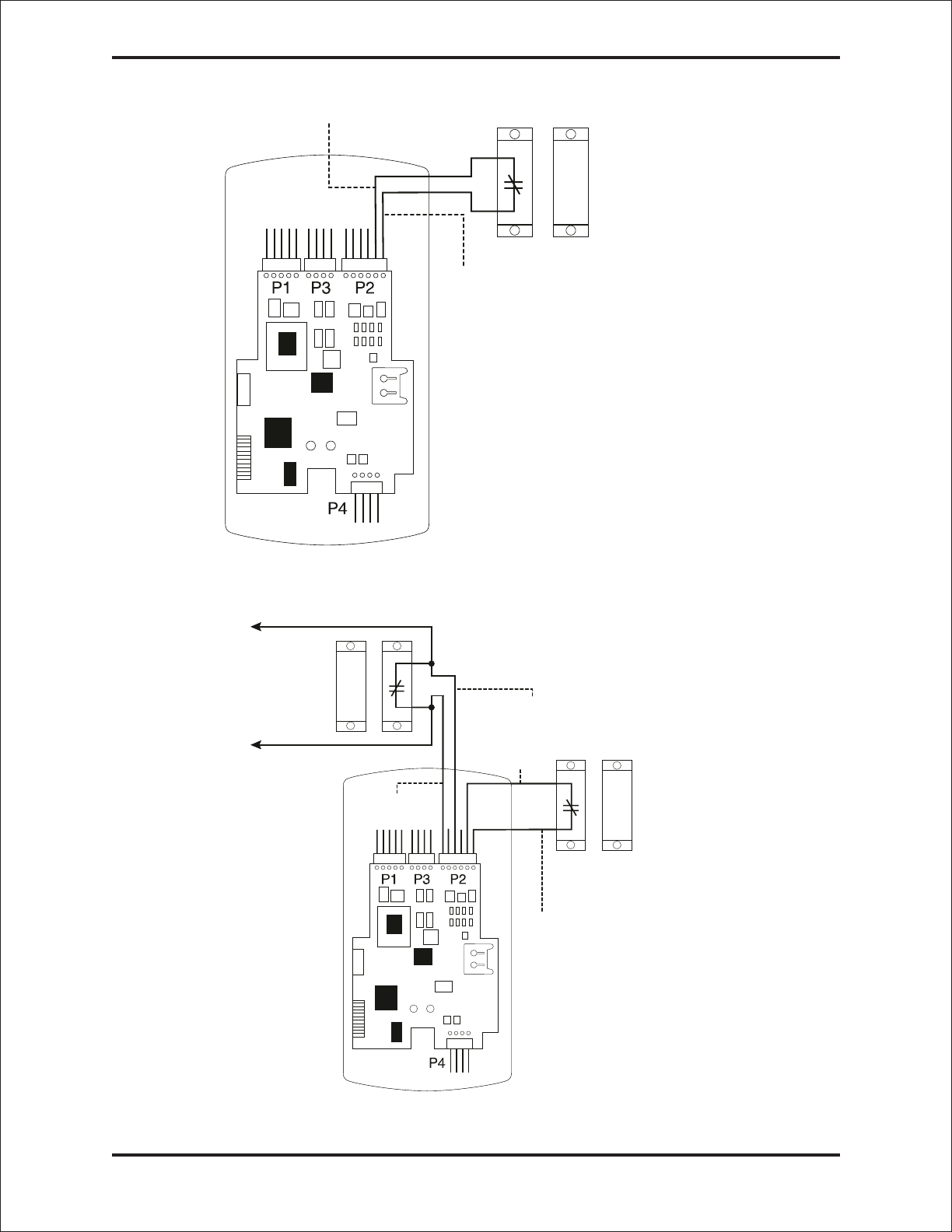
Figure 4 Wiring the Door Contact Input
P5
TO ALARM PANEL
DOOR
CONTACT
GOING BACK
TO ALARM
PANEL
TO ALARM PANEL
GREEN
(N/O)
BLUE ( C )
ORANGE
WHITE
DEDICATED DOOR
CONTACT (NC) BEING
MONITORED BY THE
prox.pad unit
Figure 5 Wiring the Aux Relay for Alarm Shunt Relay
Prox.pad plus Access System Installer Guide
Part No. 6045679, Rev. 1.0, D5 11
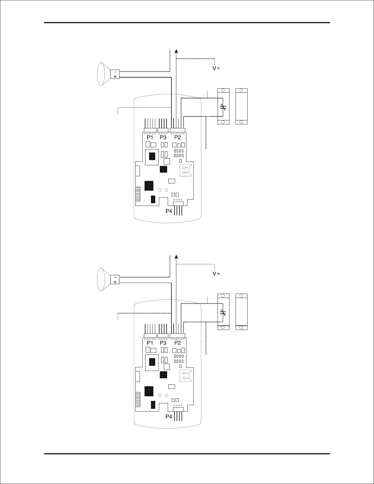
BLUE
(C)
ORANGE
WHITE
P5
DEDICATED DOOR
CONTACT (NC) BEING
MONITORED BY THE
prox.pad unit
TO POWER SUPPLY
V- V+
GREEN
(NO)
Figure 6 Wiring the Aux Relay for Forced Door Alarm
BLUE
(C)
ORANGE
WHITE
P5
DEDICATED DOOR
CONTACT (NC) BEING
MONITORED BY THE
prox.pad unit
TO POWER SUPPLY
V- V+
GREEN
(NO)
Figure 7 Wiring the Aux Relay for Propped Door Alarm
Prox.pad plus Access System Installer Guide
12 Part No. 6045679, Rev. 1.0, D5
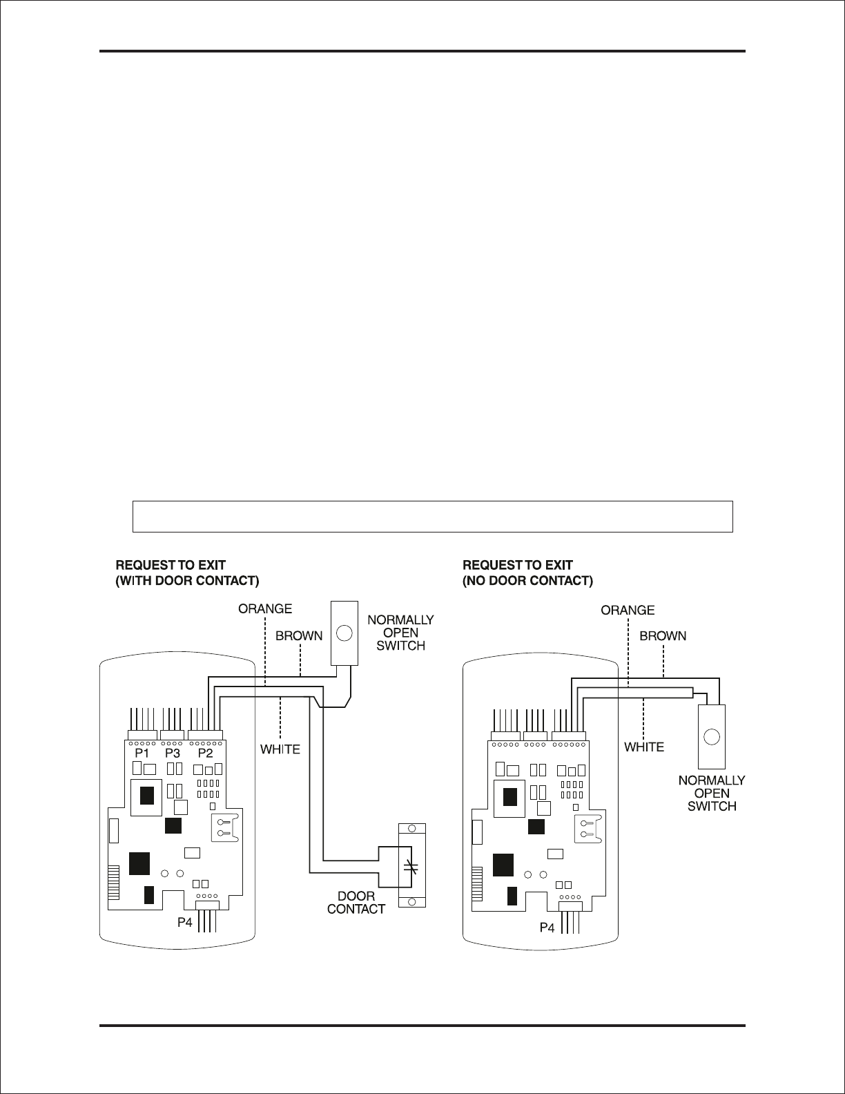
Wiring the REX Switch (Request to Exit)
The prox.pad plus unit can be wired to monitor a remote switching device, which is intended
to be installed on the “safe” side of a door. The Request to Exit (REX) switch is a momentary
input closure that engages the main relay forthesamelengthoftimeforwhichthemain
relay is programmed. This feature can be stored in the Transaction Log for viewing.
If you elect to perform a secure installation where the controller is mounted on the secure
side of the door, you can use the filler piece as a REX switch.
Other REX devices can be used to include a remote button placed at a receptionist’s desk,
a press-to-exit switch on the inside of a door, or a passive infrared detector, allowing free and
convenientegress.TheREXfeaturerequiresnoprogramming;simplywiretheunitasillus-
trated in Figure 8. To incorporate this feature, follow the steps below:
1. Turn OFF power to the prox.pad plus unit, and then remove the front keypad/controller
from the backplate.
2. Locate connector P2 on the main circuit board.
3. Plug the 6-conductor harness into connector P2. (The 2-pin jumper on pins 5 and 6
of connector P2 must be removed first.)
4. If you do not wish to install the door contacts per Figure 8, twist the white wire
and the orange wires together; this is mandatory. If this is not done, the REX
input will not function.
NOTE: The door contact MUST be closed for the REX feature to work properly.
P5 P5
(Normally Closed)
Figure 8 Wiring the REX Switch
Prox.pad plus Access System Installer Guide
Part No. 6045679, Rev. 1.0, D5 13
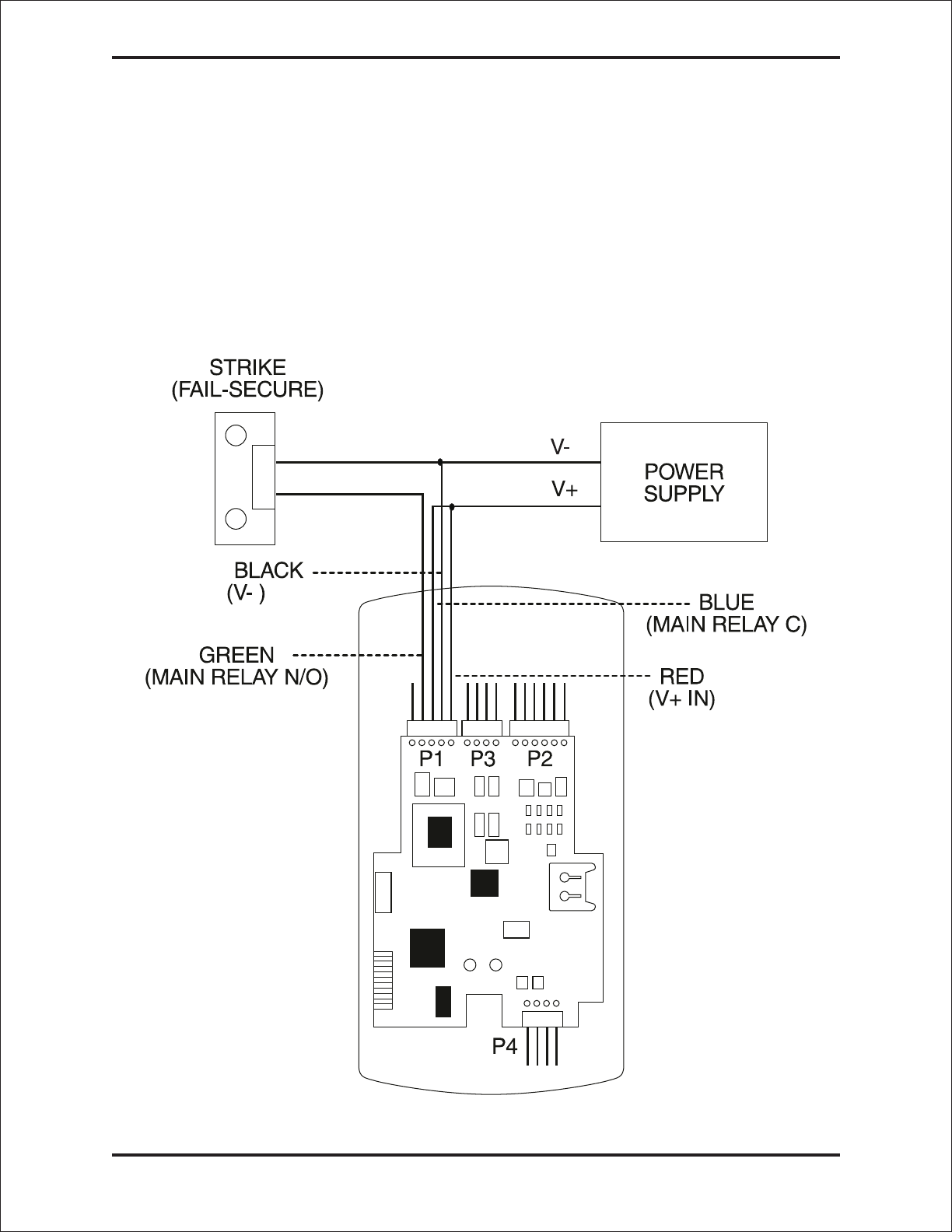
Wiring the Main Relay
The door lock is wired to connector P1 on the prox.pad plus main circuit board.
Wiring for this 5-pin connector is described in the first table on page 7. Figure 9 provides an
Electric Strike (Fail Secure) wiring diagram, Figure 10 a MagLock (Fail Safe) wiring diagram.
Power for the prox.pad plus unit must be from a minimum 10-15 volt DC linear, filtered and
regulated power supply. It is typical for the chosen power supply to power BOTH the
prox.pad plus unit and the selected locking device. When using one power supply for both
the prox.pad plus unit and locking device, be sure to include both devices in your current
requirements calculations.
NOTE: IEI recommends that you ground the power supply to earth ground.
P5
Figure 9 Electric Strike (Fail Secure Wiring Diagram)
Prox.pad plus Access System Installer Guide
14 Part No. 6045679, Rev. 1.0, D5
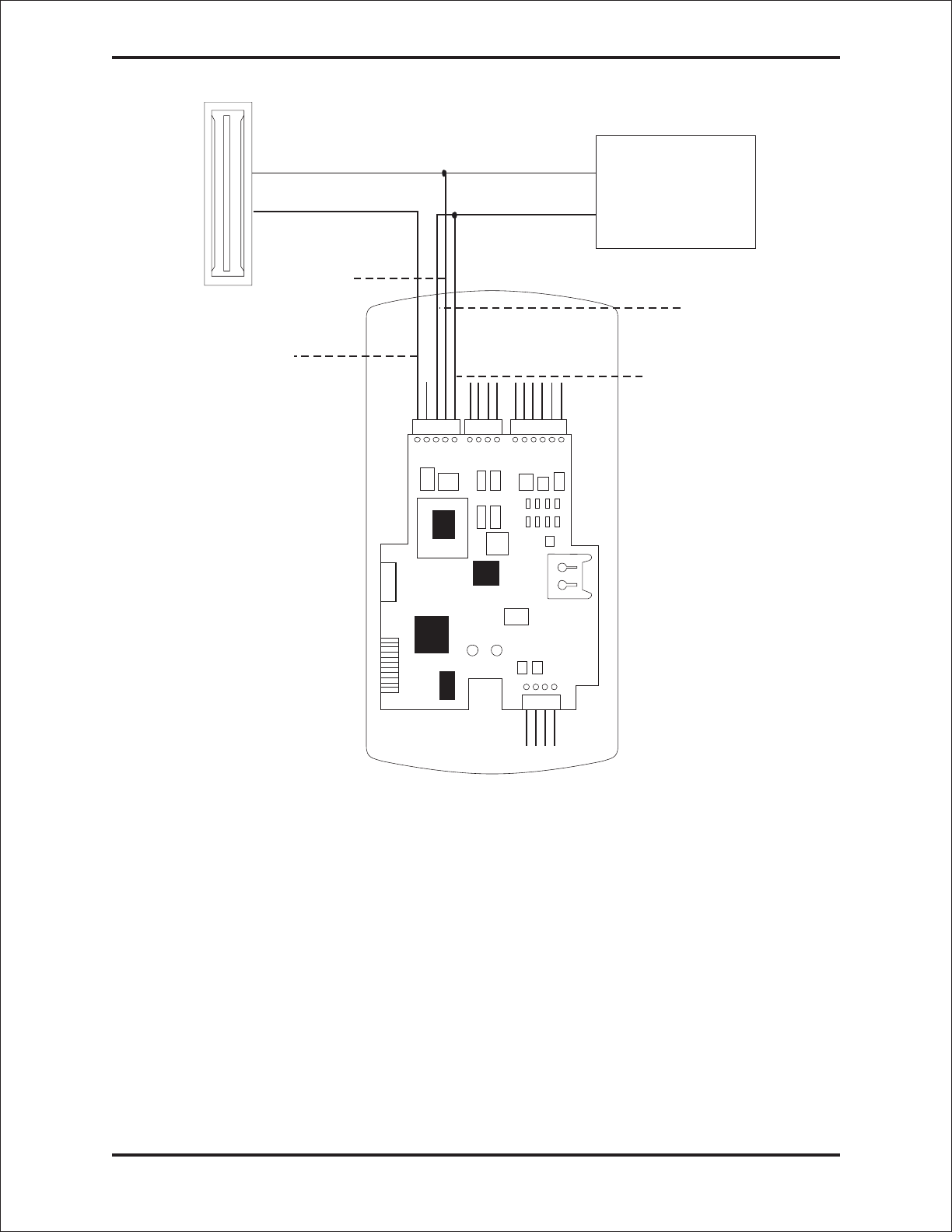
BLACK
(V-) BLUE
(MAIN RELAY C)
V-
V+
MAGLOCK
(FAIL SAFE) POWER
SUPPLY
GRAY
(MAIN RELAY N/C) RED
(V + IN)
P5
P4
P1 P2
P3
Figure 10 MagLock (Fail Safe) Wiring Diagram
Prox.pad plus Access System Installer Guide
Part No. 6045679, Rev. 1.0, D5 15
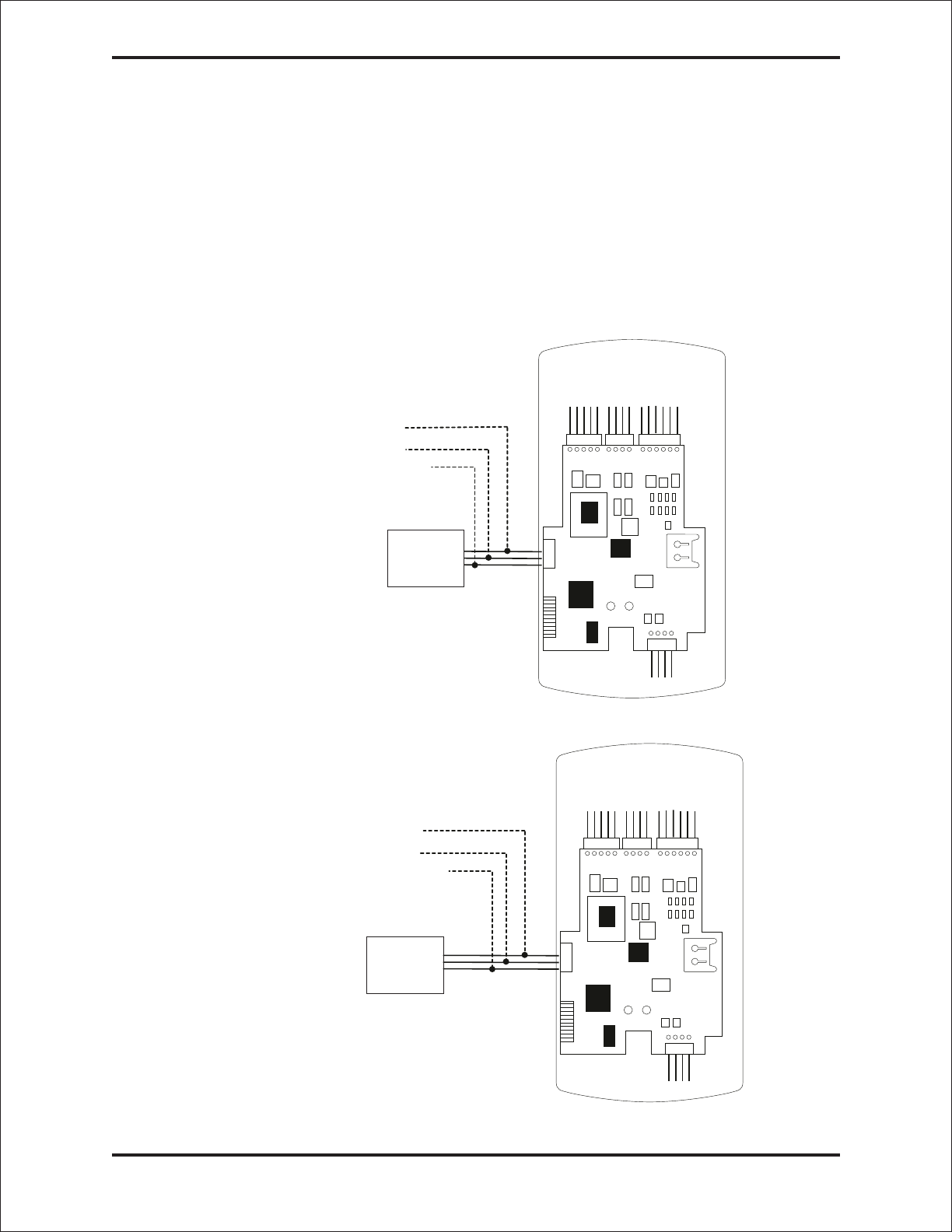
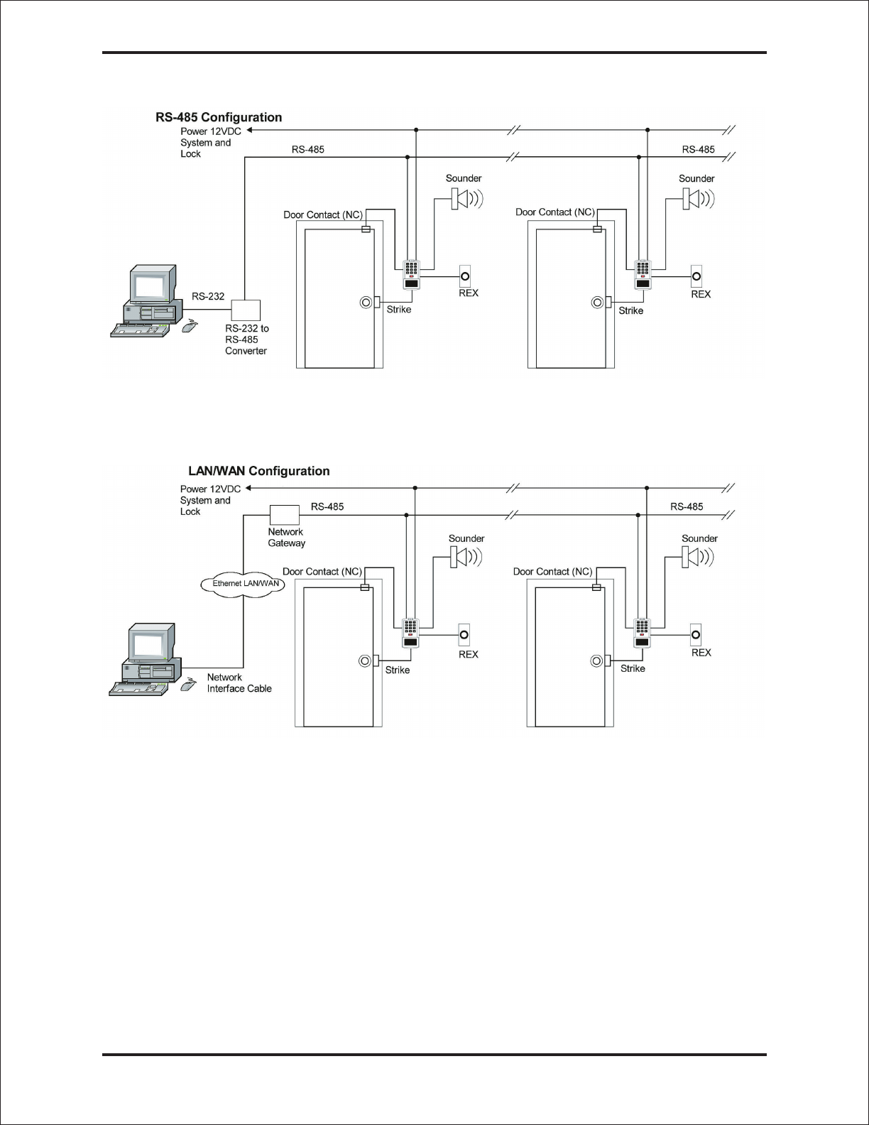
prox.pad plus Communications
The prox.pad plus is equipped with RS-485 communications with a data rate of 19200
bits/sec. This allows you to connect the unit to a personal computer (PC) either via the com-
puter’s COM (serial) port or over a computer network to manage the system using Hub Man-
agerTM Professional (v 5 or higher) software. To connect the prox.pad plus unit to a computer
COM port (which is RS-232), an RS-232 to RS-485 converter is required. To connect the
prox.pad plus unit via a computer network, the IEI Gateway device is required. The maximum
distance from the RS-485 device is 4000 feet using the specified cable. The illustrations
below show examples of both connection types. Please see the instructions for your RS-232
toRS-485converterortheinstructionsfortheIEIGatewayfordetailsaboutthosedevices.
Also, refer to the EIA RS-485 specifications for further details.
RS-232 RS-485
RS-232 to RS-485
Converter
To PC
COM port ó
2-Brown (Data A)
3-White (Data B)
4-Green (Data GND)
NOTE: The Terminator wire
may not be required.
P1 P3 P2
P5
P4
Figure 11 Connecting the prox.pad plus to a PC COM Port
RS-485
ó
To Computer
Network
2-Brown (Data A)
3-White (Data B)
4-Green (Data GND) P1 P3 P2
P5
P4
IEI Gateway
Figure 12 Connecting the prox.pad plus to a Network
Prox.pad plus Access System Installer Guide
16 Part No. 6045679, Rev. 1.0, D5
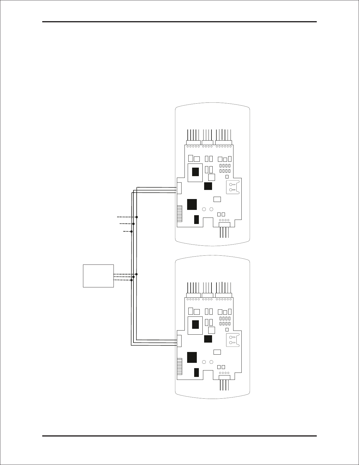
Networking Multiple prox.pad plus Units Together
For multiple door applications, the prox.pad plus can be networked together. When network-
ing prox.pad plus devices together on an RS-485 system, the prox.pad plus units are all wired
in parallel. This networking capability is available when connecting directly to your personal
computer’s COM port or when communicating over a computer network with the IEI Gateway.
The illustration below is an example of networking multiple units together.
Device #1
Device #2
Door #1
Door #2
NOTE: The maximum
number of devices on a
single network is 32.
RS-232 to RS-485
Converter or IEI
Gateway
2-White (Data A)
3-Brown (Data B)
4-Blue (Data GND)
P5
P1 P3 P2
P1 P3 P2
P5
P4
P4
Figure 13 Networking Multiple prox.pad plus Units Together
Prox.pad plus Access System Installer Guide
Part No. 6045679, Rev. 1.0, D5 17

Program Commands
In addition to personal computer (PC) programming, the prox.pad plus unit can be
programmed manually using the keypad on each unit and without the use of a personal
computer and software. Keypad programming can be helpful to get a door or doors up and
running prior to having the availability of the host computer. In all cases, the personal com-
puter programming options supersede the keypad programming options.
Defaults are in bold. See the prox.pad plus Installation/Programming Manual located on the
supplied CD-ROM for further details.
Action Desired Press Details
To enter program
mode 99 # (Master Code) *
Default Master code =
1234.
Yellow LED blinks slowly
1. Change master code
Code-only operation
(example, 4321 master
code)
1 # (new code) * (repeat code) *
1 # 4321 * 4321 *
2. Assign outputs 10 # virtual output # physical output # **
Virtual Output Physical Output
1-Lock 1-Relay1(Main)
2 - Alarm Shunt 2 - Relay 2 (Aux)
3-ProppedDoor 5-AudioAlert#1
4-ForcedDoor 6-AudioAlert#2
Entering a zero (0) for a
virtual output disables
the physical output
3. Set lock output
duration 11 # tt # 0 # * *
tt = number of seconds
to operate lock on
access (1 through 255)
defaults to 5 seconds
4. Delete users user-location # **
5. Set/clear keypad
options 30 # option # set/clear # ** See options below
Option Set/Clear
0-audio keypress feedback 0=off, 1=ON
1-visual keypress feedback 0=off, 1=ON
2-auto entry enable 0=OFF, 1=on
3-Card and PIN required for 0=OFF,1=on
Program mode
5-user lockout enable 0=off, 1=ON
7-internal REX select 0=OFF,1=on
8-user lockout select 0=BY LOCATION,
1=by group
9-timezones select 0=OFF,1=on
10-holiday timezone midnight 0=off, 1=ON
crossing
11-auto-unlock select 0=OFF,1=on
12-first-in auto-unlock 0=OFF,1=on
13-daylight savings time select 0=off, 1=ON
15-daylight savings time format 0=USA,
1=European
16-anti-passback 0=off,1=ON
17-user dump select 0=all users
1=programmed
users only
Prox.pad plus Access System Installer Guide
18 Part No. 6045679, Rev. 1.0, D5

Action Desired Press Details
6a. Print programmed
user list 25#0#0#**
6b. Print programmed
user list (starting at a
certain user)
25#0#startuser#**
7. Change keypad
parameters 32#parameter#value#** See options below
Parameter Value
0-error lockout threshold 1-50 (def=3)
1-error lockout duration 1-255 (def=10 sec)
3-extended unlock time 1-255 (def=10 sec)
4-site ID (for cmds 51, 57) 0-255 (def=11)
5-user timezone mask 0-255 (def=255)
(for programming users through
the faceplate)
6-user lockout group 0-15 (def=4)
7-lockout by group operand 0-3 (def=0)
(see below)
0=lockout users in all other groups
1=lockout users in this group
(except lockout users)
2=lockout users in higher numbered
groups
3=lockout users in lower numbered
groups
8-anti-passback delay 2-240 (1/4 second
increments, default
= 4 or 1 second
8. Set/clear auto-unlock
mask 38 # autz # set/clear # * *
autz - auto-unlock
timezone (1-8)
Entering a 1 sets the
timezone as
auto-unlock and a 0
clears it
9. Restore system
defaults (master user
and system
options/parameters only)
40 # 00000 # 00000 # * *
10. Set system time 41 # hhmm # 0 # ** hhmm=hour/minute,
24-hr format
11. Set system date 42 # mmddyy # dow # **
mmddyy=month, date,
year; dow=day of
week,1=Sunday,etc.
12. Set door number 43 # nnnnn # 0 # **
nnnnn=door number
Default=0001 (max
number=65535)
13. Set propped door
output time 44#ttt#0#**
ttt=propped door time,
to nearest 10’s
seconds, entered as
00-990; default=30 secs
entering 00 disables
propped door
Program Commands (continued)
Prox.pad plus Access System Installer Guide
Part No. 6045679, Rev. 1.0, D5 19

Action Press Details
14.Setforceddoor
output time 45#ttt#0#**
ttt=forced door time, to
nearest 10’s seconds,
entered as 00-990 (00
latches it); default=10
secs
15. Clear eeprom
memory and restore
default settings
46 # 00000 # 00000 # ** (See page 2)
User Types
0-toggle code
1-standard access
2-Log Dump
3-lockout
4-extended lockout
5-single use
6-relock code
7-emergency
16a. “Code only” user 50#type#location#keypin*keypin*
16b. “Card only” user
by presentation 50#type#location#**<presentcard>
16c. “Card AND code”
user
50#type#location#keypin*keypin*
<present card>
16d. Delete user 50#0#location#**
17. Program 26-bit
“card only” user without
presenting card
51#type#location#cardpin*cardpin*
Location must be
greater than 2;
master/supervisor
cannot be set as “card
only”
18. Program “card OR
code” user
52#type#location#keypin*keypin*
<present card>
19. Program
consecutive “card only”
users by presentation
53 # type # start user # ** <present card>
<present card> ...
Startusermustbe
greater than 2;
master/supervisor
cannot be set as “card
only”
20. Enable/disable users 56 # enable/disable # user # **
0=Enablesthatuser
1=Disablesthatuser;
master user cannot be
disabled; an
unprogrammed user
cannot be enabled or
disabled (generates a
program error)
21. Program block of
26-bit “card only” users
without presenting cards
57#numberofusers#startuser#cardpin*
card pin *
Startusermustbe
greater than 2;
master/supervisor
cannot be set as “card
only”; uses site ID set
in command 32,
parameter 4
Program Commands (continued)
Prox.pad plus Access System Installer Guide
20 Part No. 6045679, Rev. 1.0, D5

Action Press Details
22. Delete block of
consecutive users
58 # start user # start user # number of users
* number of users *
23. Dump transactions
to IR port 70#0#0#**
This command must be
used while in Program
mode
24. Set/clear event log
mask 73#event#set/clear#**
See options below; all
events are logged by
default unless stated
otherwise below
Event
1-access denied - invalid PIN
2-program denied
4-REX
5-Propped Door
6-Door Closed
7ForcedDoor
16-log dumped by user #N
17-access granted to user #N
19-access denied to user #N, bad timezone
20-togglemodeactivatedbyuser#N
(latch set)
21 - toggle mode de-activated by user #N
(latch clear)
22 - 1st in auto-unlock triggered by user #N
23 - door relocked by user #N
24 - user lockout enabled by user #N
25 - user lockout disabled by user #N
26 - access denied to user #N - user is
disabled
27 - card/code mismatch
29 - program mode started by user #N
30 - log erased by user #N
32-unprogrammedcarddata
33 - unprogrammed code data
50 - log retrieved
51 - access denied to user #N, user group
lockout
Events 30 and 50
cannot be disabled
Events 32 and 33 are
disabled by default
25. Reset (erase)
transaction log 76 # 00000 # 00000 # **
26. To exit Program
mode *(afterfinalcommand) Yellow stops flashing
Program Commands (continued)
Prox.pad plus Access System Installer Guide
Part No. 6045679, Rev. 1.0, D5 21

Led Indicators/Sounder Operations
LED or Sounder Visual/Audible
Condition Description
Yellow LED Slow blink Unit is in Program mode
Rapid blink Verify mode is active (checking that the last two
values in sequence match)
Steady Program error; to clear, press *or error lockout
Very rapid blink Memory (eeprom) erase is in progress
(commands 40/46, loop-back)
Bi-color LED Steady red Lock output deenergized
Steady green Lock output is energized (timed or latched)
Red/green alternating Awaiting second PIN during “Card AND Code”
access attempt
Green blink Auto-unlock active
Sounder
Short beep
(100 ms) every 2
seconds
Audio alert #2 is active
Sounder 1/2 sec on,
1/2 sec off Audio alert #1 is active
Double beep Lockout is canceled
Pair of double beeps Lockout is activated
3 slow beeps (250
ms), then single beep Self-test is complete
Sounder After
PIN/Card 1 single beep Valid card access
1 long beep followed
by 1 short beep User disabled
1 long beep followed
by 2 short beeps Bad timezone
1 long beep followed
by 3 short beeps User lockout
3 rapid beeps after
code entered or card
presented
Code or Card is not found
4 quick beeps First-In Auto-unlock
6 quick beeps Toggle mode is active
Prox.pad plus Access System Installer Guide
22 Part No. 6045679, Rev. 1.0, D5

prox.pad plus Specifications
ELECTRICAL
Power Supply/Current
Requirements
10-15 VDC, linear filtered and regulated power supply
500 mA (not including locking device or peripherals)
WIRING
Remote Antenna Cable
ALPHA 1174C (22AWG) 4-wire, stranded (this is required
ONLY if you choose to remote the antenna 10 feet away
from the keypad/controller)
RS-485 Cable
24AWG, shielded, two twisted-pair telephone cable with a
shunt capacitance of 16 pF/Ft (required only when using
software)
Power Supply Cable 18AWG - 22AWG 2-wire stranded (depends on distance)
Door Lock Cable 18AWG - 22AWG 2-wire stranded (depends on distance)
Door Monitor Cable 18AWG - 22AWG 2-wire stranded (depends on distance)
REX Cable (if using remote switch) 2-wire stranded
MECHANICAL
Height 5.25 in (13.3 cm)
Width 2.75 in (7 cm)
Depth 1.375 in (3.5 cm)
RELAY OUTPUTS
Main Relay - Form C (switches up to 2A)
Aux Relay - Form C (switches up to 2A)
MONITOR INPUTS
Door Position (Normally Closed, dry contact)
Request to Exit (REX, Normally Open, dry contact)
OTHER OUTPUTS
Infrared output to optional PDA program (38400 bits/sec)
SOUNDER 4000 Hz, defeatable
LEDs Bi-Color (red/green)
Yellow
Prox.pad plus Access System Installer Guide
Part No. 6045679, Rev. 1.0, D5 23

COMPATIBLE PROXIMITY
CARDS
All 26-bit HID card, including the following: ProxCard II,
IsoProx II, Duo Prox II, and Proxkey FOB; 26-bit cards are
required for manual or batch programming
UNIT CAPACITY
Users 2,000 users maximum; each user can have a card/tag, a
PINcode,oracard/tagplusaPINcode
Transactions 2,000 transactions maximum; each transaction includes
time, date, user “slot number,” and event
Lock Time 1-255 seconds
Lock Mode Access Time or Toggle/Latch
ALARM OUTPUT One of these three events can be programmed: Alarm
Shunt Relay, Forced Door Relay, or Propped Door Relay
USER ACCESS
CONFIGURATIONS
Code ONLY
Code AND Card
Card ONLY
Code OR Card
PROGRAMMABLE USER
TYPES Each user is assigned one of the following user types:
0-Toggle/latch strike
1-Normal access
2-log Dump
3-Lockout
4-Extended unlock
5-Single use
6-Relock
7-Emergency
SYSTEM USES/
INSTALLATION
CONFIGURATIONS
Suitable for small installations or remote locations,
indoors or outdoors
Wall mounted, glass mounted, or secure installation
ENVIRONMENTAL Indoor or outdoor
Operating Temperature -31° to 150° F (-35° to 66° C)
Operating Humidity 5% to 95% relative humidity, non-condensing
Prox.pad plus Access System Installer Guide
24 Part No. 6045679, Rev. 1.0, D5

This page is left blank intentionally.
Prox.pad plus Access System Installer Guide
Part No. 6045679, Rev. 1.0, D5 25

This page is left blank intentionally.
Prox.pad plus Access System Installer Guide
26 Part No. 6045679, Rev. 1.0, D5

This page is left blank intentionally.
Prox.pad plus Access System Installer Guide
Part No. 6045679, Rev. 1.0, D5 27

Questions or Problems
If you have any questions about initial prox.pad plus programming or operation, or encounter
any installation problems, contact your prox.pad plus dealer or distributor. The complete
Installation/Programming Reference manual is contained on the supplied CD-ROM.
International Electronics, Inc. © Copyright 2003 International Electronics, Inc.
427 Turnpike Street All Rights Reserved Published in U.S.A.
Canton, MA 02021 U.S.A.
Telephone: 781-821-5566 (main) 800-733-9502 (sales in MA) 800-343-9502 (sales)
Fax: 781-821-4443 Fax Info Ctr: 781-821-0734 Internet: www.ieb.com
Warranty Policy
International Electronics Inc. (IEI) warrants its products to be free from defects in material and
workmanship when they have been installed in accordance with the manufacturer’s instruc-
tions and have not been modified or tampered with. IEI does not assume any responsibility
for damage or injury to person or property due to improper care, storage, handling, abuse,
misuse, normal wear and tear, or an act of God.
IEI’s sole responsibility is limited to the repair (at IEI’s option) or the replacement of the defec-
tive product or part when sent to IEI’s facility (freight and insurance charges prepaid) after ob-
taining IEI’s Return Material Authorization. IEI will not be liable to the purchaser or any one
else for incidental or consequential damages arising from any defect in, or malfunction of, its
products.
Except as stated above, IEI makes no warranties, either expressed or implied, as to any mat-
ter whatsoever, including, and without limitation to, the condition of its products, their mer-
chantability, or fitness for any particular purpose.
Warranty Periods Are:
1 Year PowerKey
2 Years Door Gard & Secured Series Products
2 Years prox.pad and prox.pad plus
2 Years LS Series
2 Years Glass Break
5 Years ‘e’ Series Keypads
2 Years Network Gateway
All products have date code labeling to determine the warranty period. A 90-day grace period
is added to all products to account for shelf life.
Prox.pad plus Access System Installer Guide
28 Part No. 6045679, Rev. 1.0, D5