Elettronika S r l TXUD2000A 2000 Watt ATSC Transmitter User Manual TXUD2000 ATSC UHF TV TRANSMITTER PMD
Elettronika S.r.l. 2000 Watt ATSC Transmitter TXUD2000 ATSC UHF TV TRANSMITTER PMD
Contents
- 1. Transmitter User Manual Part 1
- 2. Transmitter User Manual Part 2
- 3. Exciter Manual
Transmitter User Manual Part 1

TXUD2000/ATSC UHF TV Transmitter
CODE TXUD2000/ATSC TITLE TXUD2000/ATSC UHF TV TRANSMITTER REV 0 DATE 11/02/09

SS 96 Km 113
70027 Palo del Colle (Ba) ITALY
Tel. +39 (0)80 626755
Fax +39 (0)80 629262
E-mail: elettronika@elettronika.it
Web site: http://www.elettronika.it
Registration number: IT-17686
Registration number: IT-24436

3
WARNING
The apparatus described in this manual has been designed and manufactured with devices to safe-
guard the users. In any case it is recommended that during any operation of installation, maintenance,
miscellaneous interventions and calibrations requiring the apparatus to be switched on,
THE USER TAKES ALL THE
PRECAUTIONS AGAINST INCIDENTS
It is required to use the proper clothes and protection gloves in order to prevent damages from inci-
dental contacts with high-voltage parts.
The manufacturer declines every responsibility in case the recommendations above are not followed.
IMPORTANT
The component lists attached to the relevant electrical diagrams indicate for each item the reference,
the description and the type normally used.
The Elettronika S.r.l. though reserves the right to use or supply as spare parts components with
equivalent characteristics but of a different type, assuring anyway the optimal work of the apparatus
in accordance with the specifications.
The enclosed monographs are solely owned by Elettronika S.r.l.
The use of anything enclosed in this technical manual without explicit authorization given by Elettronika
S.r.l. will be prosecuted by the law.
The data and technical characteristics of the apparatus described in this manual are not compelling for
the manufacturer.
The Elettronika S.r.l. reserves the right to make, without previous notice, modifications or updates in
order to improve the quality of the product.
The general conditions of supply and sale are described in the contracts.
The delivery time are in accordance with the products and quantities ordered.

4
Summary of warranty
We, ELETTRONIKA S.r.l., SS096 Km 113 Z.I. PALO DEL COLLE (BA) ITALY, warrant to the ORIGINAL PURCHASER of a NEW product, for a
period of one (1) year from the date of purchase by the original purchaser (the “warranty period”) that the new ELETTRONIKA product is free of defects
in materials and workmanship and will meet or exceed all advertised specifications for such a product. This warranty does not extend to any subsequent
purchaser or user, and automatically terminates upon sale or other disposition of our product.
Items excluded from this ELETTRONIKA warranty
We are not responsible for product failure caused by misuse, accident, or neglect. This warranty does not extend to any product on which the serial
number has been defaced, altered, or removed. It does not cover damage to loads or any other products or accessories resulting from ELETTRONIKA
product failure. It does not cover defects or damage caused by use of unauthorized modificstions, accessories, parts, or service.
What we will do
We will remedy any defect, in material or workmanship (except as excluded), in our sole discretion, by repair, replacement, or refund. If a refund is
elected, then you must make the defective or malfunctioning component available to us free and clear of all liens or other encumbrances. The refund will
be equal to the actual purchase price, not including interest, insurance, closing costs, and other finance charges less a reasonable depreciation on the
product from the date of original purchase. Warranty work can only be performed at our authorized service centers or at our factory. Expenses in
remedying the defect will be borne by ELETTRONIKA, including one-way surface freight shipping costs within the United States. (Purchaser must bear
the expense of shipping the product between any foreign country and the port of entry in the United States and all taxes, duties, and other custom’s fee(s)
for such foreign shipments).
How to obtain warranty service
You must notify us of your need for warranty service not later than ninety (90) days after the expiration of the warranty period. We will give you an
authorization to return the product for service. All components must be shipped in a factory pack or equivalent which, if needed, may
Desclaimer of consequential and incidental damages
You are not entitled to recover from us any consequential or incidental damages resulting from any defect in our product. This includes any damage
to another product or products resulting from such a defect.
Warranty alterations
No person has the authority to enlarge, or modify this warranty. The warranty is not extended by the lenght of time for which you are deprived of
the use of the product. Repairs and replacement parts are provided under the terms of this warranty shall carry only the unexpired portion of this
warranty.
Design changes
We reserve the right to change the design of any product from time to time without notice and with no obligation to make corresponding changes in
products previously manufactured.
Legal remedies of purchaser
There is no warranty which extends beyond the terms hereof. This written warranty is given in lieu of any oral or implied warranties not contained
herein. We disclaim all implied warranties, including without limitation any warranties of merchantability or fitness for a particular purpose. No action
to enforce this warranty shall be commenced later than ninety (90) days after expiration of the warranty period.
Warranty for electronic tubes
The warranty applied for electronic tubes is the one given by the manufacturer of the tube. In the event that the product shows anomalies within the
deadline of the validity of the warranty given by the manufacturer of the product itself, the buyer will have to return it to the seller with the needed
documents and the written description of the defect. The seller will ship the broken tube to the manufacturer in order to effect the necessary technical
tests to find out the cause of the anomaly. Meanwhile the buyer of the tube who needs to use, and as such to replace immediately the product, will have
to buy a new one and provide to the relevant payment, further to the issuing by the seller of a regular commercial invoice. After the adequate tests made
by the manufacturer, should the result be positive, that is confirm the defect in manufacturing, the seller will issue a regular credit note in the name of
the buyer and return the amount paid. Should the result be negative, that is detect a negligence in the installation or use by the buyer, he will have no
right against the seller.
Warranty

5
INTRODUCTION
The apparatus described in this manual is the latest of this series, offering high performances, remark-
able reliability and a wide range of characteristics, it all at a competitive cost.
Its is easy to install and use. It only takes to follow the installation procedure as shown in this manual:
after having removed all from the package, you only have to follow step by step the description in the
various sections.
Before starting to use the apparatus, remember to:
read carefully the general safety information contained in this section;
follow the instructions for the installation and set up of the apparatus;
read all the remaining sections of this manual in order to know well the apparatus and learn
how to obtain the best of its characteristics.
CONTENTS OF THE MANUAL
The chapter composing this manual contain all the information concerning the use of the apparatus.
For more information refer to ELETTRONIKA S.r.l.
This manual is made up of different chapters, each made up of various sections.

6
WARNING!
The currents and voltages in this equipment are dangerous!
Personnel must at all times observe safety regulation!
This manual is intended as a general guide for trained and qualified personnel who are aware of the
dangers inherent in handling potentially hazaedous electrical and electronic circuits.
It is not intended to contain a complete statement of all safety precautions which should be observed by
personnel in using this or other electronic equipment.
The installation, operation, maintenance and service of this equipment involves risks both to personnel
and equipment, and must be performed only by qualified personnel exercising due care.
Elettronika S.r.l. shall not be responsible for injury or damage resulting from improper procedures or
from the use of improperly trained or inexperienced personnel performing such tasks.
During installation and operation of this equipment, local building codes and fire protection standards
must be observed.
WARNING!
Always disconnect power before opening covers,
doors, enclosures, gates, panels or shields.
Always use grounding sticks and short out high
voltage points before servicing. Never make
internal adjustments, perform maintenance or
service when alone or when fatigued.
Do not remove, short-circuit or tamper with interlock switches on access covers, doors, enclosures,
gates, panels or shields.
Keep away from live circuits, know your equipment and don’t take chances.
WARNING!
In case of emergency ensure that power has been disconnected.

7
A - AIRWAY
If unconscious, open airway lift up neck, push
forehead back, clear out mouth if necessary,
observe for breathing.
Treatment of electrical shock
1) If victim is not responsive follow the A, B, C’s of basic life support.
PLACE VICTIM FLAT ON HIS BACK ON A HARD SURFACE
B - BREATHING
If not breathing, begin artificial breathing. Tilt
head, pinch nostrils, make airttght seal, 4 quick
full breaths. Remember mouth to mouth resuscita-
tion must be commenced as soon as possible.
C - CIRCULATION
Check carotid pulse. If pulse
absent, begin artificial circulation. Approx. 80sec.: 1 rescuer, 15 compressions, 2 quick breaths.
Approx. 60sec.: 2 rescuers, 5 compressions, 1 breath.
NOTE: DO NOT INTERRUPT RHYTHM
OF COMPRESSIONS WHEN SECOND PERSON
IS GIVING BREATH.
Call for medical assistance as soon as possible.

8
2) If victim is responsive:
- keep them warm;
- keep them as quiet as possible;
- loosen their clothing (a reclining position is recommended).
FIRST-AID
Personnel engaged in the installation, operation, maintenance or servicing of this equipment are urged
to become familiar with first-aid theory and practices. The following information is not intended to be
a complete first-aid procedure, it is brief and is only to be used as a reference. It is the duty of all
personnel using the equipment to be prepared to give adequate Emergency First Aid and thereby pre-
vent avoidable loss of life.
TREATMENT OF ELECTRICAL BURNS
1) Extensive burned and broken skin.
- Cover area with clean sheet or cloth (cleansed available cloth article);
- do not break blisters, remove tissure, remove adhered particles of clothing, or apply any salve or
ointment;
- treat victim for shock as required;
- arrange transportation to a hospital as quickly as possible;
- if arms or legs are effected keep them elevated.
NOTE
If medical help will not be available within an hour and the victim is conscious and not vomiting, give
him a weak solution of salt and soda: 1 level teaspoonful of salt and 1/2 level teaspoonful of baking
soda to each quart of water (neither hot or cold).
Allow victim to sip slowly about 4 ounces (half a glass) over a period of 15 minutes.
Discontinue fluid if vomiting occurs (do not give alcohol).
2) Less severe burns - (1st & 2nd degree).
- Apply cool (not ice cold) compresses using the cleansed available cloth article;
- do not break blisters, remove tissue, remove adhered particles of clothing, or apply salve or ointment;
- apply clean dry dressing if necessary;
- treat victim for shock as required;
- arrange transportation to a hospital as qickly as possible;
- if arms or legs are affected keep them elevated.

9
Further to the directives issued by the European Community, 2002/95/CE, 2002/95/CE and 2003/108/
CE, and to the Italian Decree of Law n° 151 dated 25 July 2005, this is to inform the customers of Elettronika
S.r.l. living within the boundaries of the European Community about the following obligations:
1) It is forbidden to trash RAEE products (which includes all broadcasting products which are not expressly
labelled as lead-free) along with normal wastes;
2) Such devices must be brought to proper centres able to perform the adequate processing in order to
recycle their parts where possible and dispose of the raw materials contained therein;
3) For equipment purchased from Elettronika after the 13th of August 2005, the gathering, transport, processing,
recycle and disposal operations are responsibility of Elettronika who will bear all related expenses;
4) For equipment purchased from Elettronika before the 13th of August 2005 , the gathering, transport,
processing, recycle and disposal operations are responsibility of Elettronika, who will bear all related expenses,
only if you are purchasing from us new equipment in substitution of the disposed one;
5) Electric and electronic devices contains lead in soldering, cables, etc. This substance pollutes the environment
and may be accumulated in the organism of plants and mammals. It is dangerous for humans because it may
affect blood, bone marrow, peripheral and central nervous system and kidneys, causing anaemia,
encephalopathies (e.g., convulsions), peripheral neuropathies, cramps of the abdomen and kidney damages.
Besides it affects human reproduction and growth.
These devices also contain mercury. From the environmental point of view, this substance is highly toxic for
aquatic life, and can be accumulated in the organism of fish.
Long-term damages to humans can affect the central nervous system and the kidneys, producing irritability,
emotional instability, tremors, damages to the mind and the memory, language disorders. It may also irritate
and whiten the gums, and its effects may be cumulative. Based on tests on animals, it may affect the human
reproduction or growth.
There is also chrome, which may result in irritation of the eyes and respiration system.
Cadmium is also present. In humans it may damage lungs, due to repeated or prolonged contact with its dust,
and kidneys. It may cause cancer.
6) The symbol below marks the devices which cannot be disposed of along with normal wastes, as stated in
1) and 2) above.
7) The payment of fees is foreseen for the non-allowed disposal of such devices.
Communication N°1 -2002/95/CE - RoHS Directive

10
This page is intentionally blank

11
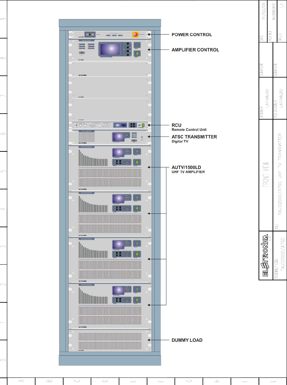
TXUD2000/ATSC
UHF TV TRANSMITTER
User’s manual

12
TXUD2000/ATSC UHF TV TRANSMITTER
DESCRIPTION
The TXUD2000/ATSC belongs to the High Power UHF products family of Television Transmitters fully in
LDMOS solid state technology.
The TXUD2000/ATSC series represents the 2kW ATSC TV transmitter operating in the UHF Band for
Common amplification process (separate amplification available) of the Video and Audio carriers and for
Digital TV signals of different standards. This transmitters family has been designed to offer to the customer
high performances, high reliability and greater simplicity in their operation and maintenance procedures.
The Video and Audio signal processing is provided for all Analogue and Digital TV Standards and all types of
Audio applications (Mono and Dual Sound - NICAM) together with colour systems such as PAL - NTSC -
SECAM. The transmitter ensures optimal performance also with Digital TV signals (DVB-T, ATSC, DTMB,
etc.). Thanks to the amplitude and phase pre-correction circuit, it is possible to cancel the distortions in the
output stage, thus cutting down the operating costs. The RF transposition in the driver is carried out by a
synthesizer with various possibilities of accuracy and stability as well as precision offset locked by internal or
external frequency reference.
When equipped with a dual-mode exciter (Analogue and DVB-T), the transmitter can quickly and easily
switch from analogue broadcasting mode to DVB-T broadcasting mode (and vice versa), to enable a
comfortable operation during the transition period to the full-digital broadcasting time.
The RF Amplifier is made up by four RF Amplifier Modules installed in a power rack; the modules are
dedicated for the Video and Audio carriers common amplification and for Digital TV amplification. The
amplifiers employ solid state LDMOS technology in order to obtain wide band, reliability, and high efficiency.
Each RF module has a built-in switching-mode power supply unit, self-protected against overcurrents and
overvoltages, as well as overtemperature and VSWR for RF parameters. The cooling system is fully contained
into the transmitter. The Amplifier Control unit provides full management of the transmitter without the presence
of the operator, the system includes a central controller and several peripheral units installed in each RF
module and rack. Controller and peripherals are connected by a RS485 full-duplex bus.
Power supply output voltages and currents, Forward and Reflected Powers of any single power amplifier are
monitorized by Amplifier Control unit.
In that way there is a single interface point between user and all the transmitter. The operator inter-face is
made by a high resolution LCD graphic display and a simple keyboard, the menu is very friendly and easy to
use.
The Amplifier Control unit can be fully controlled in 'remote' mode via link or via modem in RS232 or other
interface.
The equipment design allows the soft degradation (RF power loss) for several transistors faults.

13
TECHNICAL CHARACTERISTICS
RF SECTION
Analog Operation
Frequency Range ............................................................................................................................................. 470 - 860MHz
Output Power .......................................................................................................................................................... 5kW PEP
Gain (±2) ......................................................................................................................................................................... 27dB
Video / Audio Power Ratio ...................................................................................... 10/1 single sound - 20/1/0.2 dual sound
Out Stage Technology ............................................................................................................................Solid State LDMOS
Video / Audio Amplification ..................................................................................................................................... Common
Standards ................................................................................................................................................................ G, K, I, M
Sound Transmission .................................................................... FM single sound - Dual sound coding IRT - NICAM 728
Harmonics and Suppression Emission ..................................................................................... In compliance with CCIR rec.
Intermodulation Products from Video and Audiio....................................................................................................... < 50dB
Frequency Stability .........................................................................................................................2.5ppm (option 0.05ppm)
RF Input Connector ................................................................................................................................................ N Female
RF Output Connector........................................................................................................................................... EIA 1+5/8”
Digital Operation
Output Power (DVB-T) ...................................................................................................................................... 1200W RMS
Output Power (ATSC) ........................................................................................................................................ 2000W RMS
DVB-T Modes ......................................................................................................... All the modes listed in ETSI EN 300 744
DVB-T MER ....................................................................................................................................................... > 33dB RMS
DVB-T Shoulders Attenuation (After non-critical mask 6-cavity filter) ............................................................. > 40dB RMS
DVB-T Output Spectrum .............................................................................................................Compliant ETSI EN 300 744
ATSC Symbol Rate ...................................................................................... 10.76MBaud/s (Compliant to ATSC Doc. A/53)
ATSC SNR ......................................................................................................................................................... > 27dB RMS
ATSC Shoulders Attenuation (After simple mask cavity filter ref. total output power) ..................................... > 46dB RMS
ATSC Output Spectrum ......................................................................................................... Compliant to ATSC Doc. A/64
VIDEO SECTION
Video Input ........................................................................................................................................... BNC 75Ω Connector
Nominal Input Level ............................................................................................................................................. 1Vpp ±6dB
Return Loss................................................................................................................................................................. > 30dB
DC Restoration ........................................................................... Clamped to the blanking level without affecting the burst
White Limiter ............................................................................... At 90% picture signal without affecting the chrominance
Transmission characteristics
Sideband Spectrum Response .....................................................................................................According to the standard
Amplitude Frequency Response .................................................................................................According to the standard
Group Delay variation without receiver pre-correction and TV demodulator flat ..................................................... < ±35ns
Non Linearity Distortion (10 to 75% mod.) .................................................................................................................... < 5%
Differential Gain (10 to 75% mod.) .................................................................................................................................. < 5%
Differential Phase (10 to 75% mod.) .................................................................................................................................< 5°
Signal to random noise ratio (weighted 0.2 to 5MHz) ................................................................................................. > 60dB
Blanking Level Variation ................................................................................................................................................ < 2%
2T k Factor ..................................................................................................................................................................... < 2%

14
AUDIO SECTION
Nominal Input Level (±50kHz dev.) ................................................................................................................... -10 to +8dBm
Input Impedance ............................................................................................................................................ 600Ω balanced
Pre-emphasis .................................................................................................................................................................. 50µs
Transmission characteristics
Amplitude Frequency Response ......................................................................................................... 40 to 15000Hz ±0.5dB
Total Harmonic Distortion ........................................................................................................................................... < 0.5%
FM Signal to noise ratio (referred to ±50kHz dev. f = 400Hz) ....................................................................> 60dB (weighted)
AM Signal to nokise ratio ............................................................................................................. > 50dB (referred to 100%)
AM Synchronous Modulation ..................................................................................................... > 40dB (referred to 100%)
METERING
Output Forward Power (Peak or RMS)
Output Reflected Power (Peak or RMS)
Unbalance Power (last unbalance load in output combiner)
Transmitter Temperature
Power Amplifier Forward Power (Peak or RMS)
Power Amplifier Reflected Power (Peak or RMS)
Power Amplifier Input Power (Peak or RMS)
Power Amplifier Heatsink Temperature
Pallet Current
Power Supply Voltage
Working Timer
INDICATIONS
Cooling Blower Working (with icon on front display)
Transmitter Interlock (with icon on front display)
Alarm (with red LED on front panel)
Transmitter ON/OFF (with green LED on front panel)
Remote ON/OFF (with orange LED on front panel)
Input Mains Phase Missing (with green LED on Power Control panel)
PROTECTIONS
Mains Phase Lack
Output Forward Power
Output Reflected Power
Rack Cooling Failure
Power Amplifier Forward Power
Power Amplifier Reflected Power
Power Amplifier Heatsink Temperature
Module Current
Power Supply Voltage
REMOTE CONTROL SECTION
Parallel Interface ........................................................................................................................... ON/OFF, Alarms, Interlock
Serial Interface ...................................................................................... RS232 or RS485 (Full monitoring and management)

15
GENERAL
Power Supply Voltage ................................................................................................... 3P+N 380V ±15%, 3P+N 230V ±15%
Power Supply Frequency ........................................................................................................................................ 50 - 60Hz
Power Factor .................................................................................................................................................................> 0.98
Analog Power Consumption (Black) ....................................................................................................................... 13.45kVA
Digital Power Consumption (DVB-T) .......................................................................................................................... 9.0kVA
Digital Power Consumption (ATSC) ......................................................................................................................... 10.2kVA
Housing .........................................................................................................................................................1 Rack 19”-42U
Weight (Amplifier / Rack)................................................................................................................................. 485kg / 500kg
AirFlow ................................................................................................................................................................... 2500m3/h
Temperature ..................................................................................................................................................... -5°C to +45°C
Isolation Transformer (Power / Weight)...........................................................................................................20kVA / 250kg
Specifications and characteristics are subject to change without notice
16
INSTALLATION REQUIREMENTS
This section explain how to install and configure the transmitter for your location All internal switching and
setup should be done by qualified service person.
PARAMETER REQUIREMENTS
TRANSMITTER
ROOM The room should be clean and free of dust. The building floor
shuold be able to support a load capacity >1000kg/m2
INSTALLATION
AREA
The transmitter should be installed to have space around enough
for ventilation and for maintenance actions to be allowed.
The minimun requirement space is one meter outer boundary of
transmitter.
TEMPERATURE The transmitter is designed to work from -5° up to 45°C, anyway
to ensure long life is better to keep the room temperature lower
than 35°C.
ELECTRICAL
PLANT
The transmitter power consumption is <10.2kVA (13.45kVA in
analog mode), we suggest to design the main power line
capacity increased by at least more than 50%.
MAINS SYSTEM The mains system should be three phase with neutral. The
trasmitter is available in two different mains voltage models for
380VAC and 230VAC system.
AIR COOLING The outlet air should be convoyed out of the room by suitable ducts
(the transmitter air output adapters has a diameter of 320mm).
The air flow required is 2500m3/h.
ANTENNA
The transmitter RF output interface is EIA 1+5/8” (others interface
can be supplied on request in order to match the antenna feeder
or combiner input). The RETURN LOSS of the system should be
greater than 27dB in the operation channel.
Note: the standard cooling system is supplied with internal ventilation system, air inlet and outlet are
on the top. Other different installations can be proposed for various air connection arrangements.

17
SWITCH ON PROCEDURE
Before to switch on the Transmitter is extremely important to check:
- The right connections for the RF system (antenna or external combiner) and take greatest care for the Inner
in each coaxial connections;
- the right connections with the Mains Power Supply network, the Neutral line must be present and connected,
and the correspondence with the voltage nominal value request;
- the right working of the earth-ground connections system, for people safety and transmitter right operation;
- the right connections inside the transmitter with input/output RF cable to/from amplifier block and combiner/
divider system, if for transport or installation reason you had disconnected them before.
To follow with first switch on please follow the below indications:
- Set in OFF position all the frontal switch, Main, Amplifier Control and Amplifiers Block;
- turn ON the Mains and the Amplifier’s switch. The Amplifier Control checks the communications with the
amplifier block. If the communication is ok you can turn ON the Amplifier Control, now automatically the
rack’s blowers and the exciter are switched ON;
- give little power in to the amplifier and check if all the indicator are in the right situation (no reflected, no
unbalance on the Amplifier Control, more or less the same indication for current and power for all the
amplifiers block);
- increase the power slowly slowly. At rated maximum output power some watts might be shown as Reflected
Power due to isolation of directional coupler or return loss from antenna system.
EXCITER DESCRIPTION
The ATSC TRANSMITTER is an 8-VSB ATSC professional exciter, designed for the most demanding
digital TV broadcasting applications. It integrates a modulator module with up-to-date FPGA technology and
advanced digital signal processing algorithms in order to generate an absolutely accurate output 8-VSB signal,
with exceptionally optimized modulation and the output filtering techniques.
Very high linearity performances are possible thanks to very careful RF design over the entire VHF and UHF
bands and with an optimal digital precorrection engine working simultaneously in the time and frequency
domains. A high degree of reliability is guaranteed, moreover, by the use of oversized cooling devices and by
control circuits operated by modern microprocessor technologies. The ATSC TRANSMITTER can be used
as a stand-alone 5W RMS transmitter or as a driver stage for amplifiers of greater power. The excellent
spectral purity of the conversion oscillator lets the ATSC TRANSMITTER radiate an 8-VSB signal with an
excellent MER value. The ATSC TRANSMITTER is equipped with a powerful ASI/SMPTE inputs management
block which allows to manage the Transport Stream (TS) inputs in a fully redundant configuration, thus
significantly improving the reliability of the whole broadcasting system in every operating condition.
The ATSC TRANSMITTER is totally compliant to the A/53, A/54 and A/64 ATSC recommendations with
6MHz output channel bandwidth, in VHF and UHF bands.

18
RF AMPLIFIER MODULE DESCRIPTION
The RF Amplifier Modules place in the TXUD2000ATSC Transmitter station are equipment designed to
simplify transport and installation. Born to ensure high working reliability they excel also for their great
performance.
Thanks to the excellent linearity of the amplifiers, achieved with the use of the state-of-the-art LDMOS
(UHF) technology, these equipment allow excellent performance both with analog and digital TV signals.
The design redundancy (a power supply for every MOS device), the oversized unbalanced power dummy
loads, the wide input range of the switching-mode power supplies, allow a NO STOP transmission 24h per
day. The temperature of the amplifiers is guaranteed by a forced air cooling system extremely noiseless.
The presence of Amplifier Control that collects all measures from amplifiers and from antenna system ensure
a single control point to access to all MOSFET currents, power supplies voltages, temperature of the heat
sinks, amplifiers output powers together with the RF power reading of the output antenna system.
A multifunctional display on the Amplifier Control makes it possible to verify all the operating parameters of
the unit. The amplifiers in the series are remotable by wired telemetry connector or by serial communication,
RS232 on front panel or RS485 on rear panel of the Amplifier Control.
CHANNEL CHANGE PROCEDURE
To proceed with a channel change operation, please follow the below indications:
- Follow the channel change indications on users manual of the exciter;
- from each RF Amplifier Modules select the new closest channel frequency;
- tune the Bandpass Output Filter on new channel;
- if the difference with the two channel is less than 10 you don’t need to change the power amplifier phase
balance. Otherwise, connect a digital meter to a DC Monitor (BNC) on each dummy load and keep low the
value, by tuning the microstrip length on the input divider;
- connect a Wattmeter and a Dummy Load;
- set the rated output power and tune the right Forward Power indication on the Amplifier Control display;
- set the output at 10% of the rated ones, swap the Forward and Reflected cable on the rear of the Amplifier
Control and set the reflected indication.
The 3dB Output Coupler is a wide band type and don’t need any tuning operations.
DIGITAL UPGRADE
The amplifier is ready to operate with a DVB-T signal keeping the same analogue high performance.
- Replace the analogue Bandpass Filter with a digital ones (critical or not critical mask are well supported);
- select the RMS Detector instead of peak one on Amplifier Control and on each power amplifier to have the
right power indication and the new power alarm threshold;

19
- replace the analogue Cxciter with a DVB-T ones. If you use a DVB-T Modulator with IF output you can
use the IF VEGA input;
- the output power should be around 1/4 (in DVB-T mode) or 1/3 (in ATSC mode) of the analogue rated power
(for example: the 5kW = 1.2kW rms in DVB-T mode or 5kW = 2.0kW rms in ATSC mode).

20
Elettronika Code Description Qty Page 1/2
01404 BYPASSING CAPACITOR 2
02015 BNC CONNECTOR FOR RG58 CABLE 7
02408 90° 7/16” MALE-90° 7/16” FEMALE CONNECTOR 1
02459 EIA 1+5/8” INNER CONNECTOR 1
02502 SMA SOCKET FOR RG58 CABLE 3
02526 EIA 1+5/8” RIGID LINE 1.00
02527 EIA 1+5/8” ANGLE 5
02791 DB9 MALE SOCKET PANEL MOUNTING 7
02844 2 POLES SHIELDED SOCKET 2
02865 4 POLES SHIELDED SOCKET 2
02871 DB9 SHELL 7
02886 3m 16A MALE/FEMALE CABLE 1
02893 3 WAY MALE SCREW TERMINAL 3
02894 3 WAY FEMALE SCREW TERMINAL 3
03205 HP 5082/2800 DIODE 2
05447 ALLOY COPPER BAR DRILLED 3
05448 M6 BAR METALS 1
06648A EIA 1+5/8” DIRECTIONAL COUPLER 1
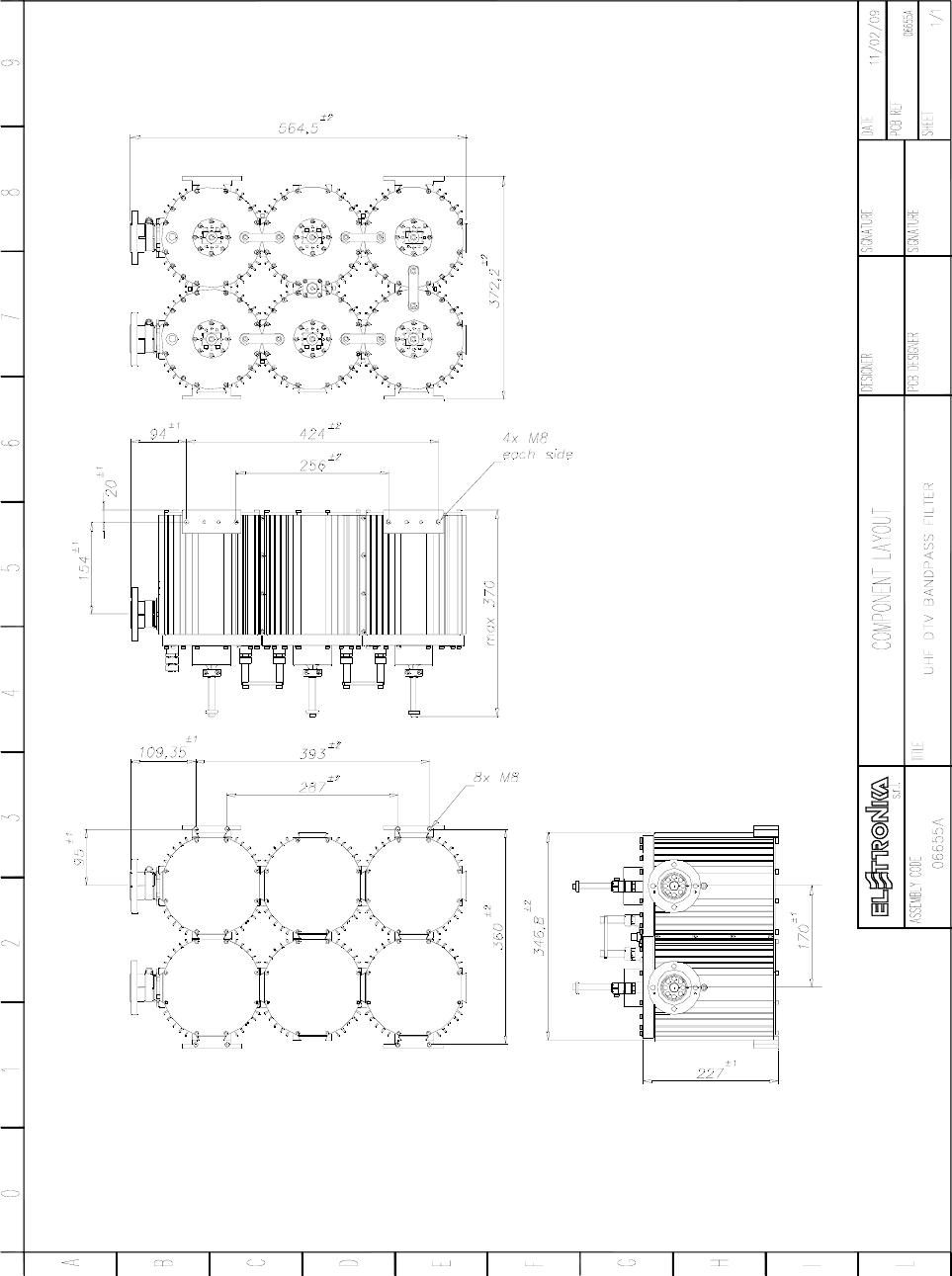
06655A UHF DTV BANDPASS FILTER 1
06870 90° EIA +15/8” MECHANICAL DETAIL 1
07528A 2 POLES 16A CURRENT DEVICES 1
07549 4x63A CURRENT DEVICES 1
07550A 1P+N 500V FUSE-HOLDER 1
07553 220V GREEN LIGHT 1
07558B TIMER MODULAR FINDER 1
07574 63A CONTACTOR 1
07620 HIGH GRID 2
07625 EBM BLOWER 2
07625A 3uF CAPACITOR 2
07810 AC FILTER 1
07970 PVC PROTECTION 2
08504 RG58 50Ω CABLE 14.00
A9029 7.5kW UHF MULTICOUPLER 1
APG012C AMPLIFIER CONTROL 1
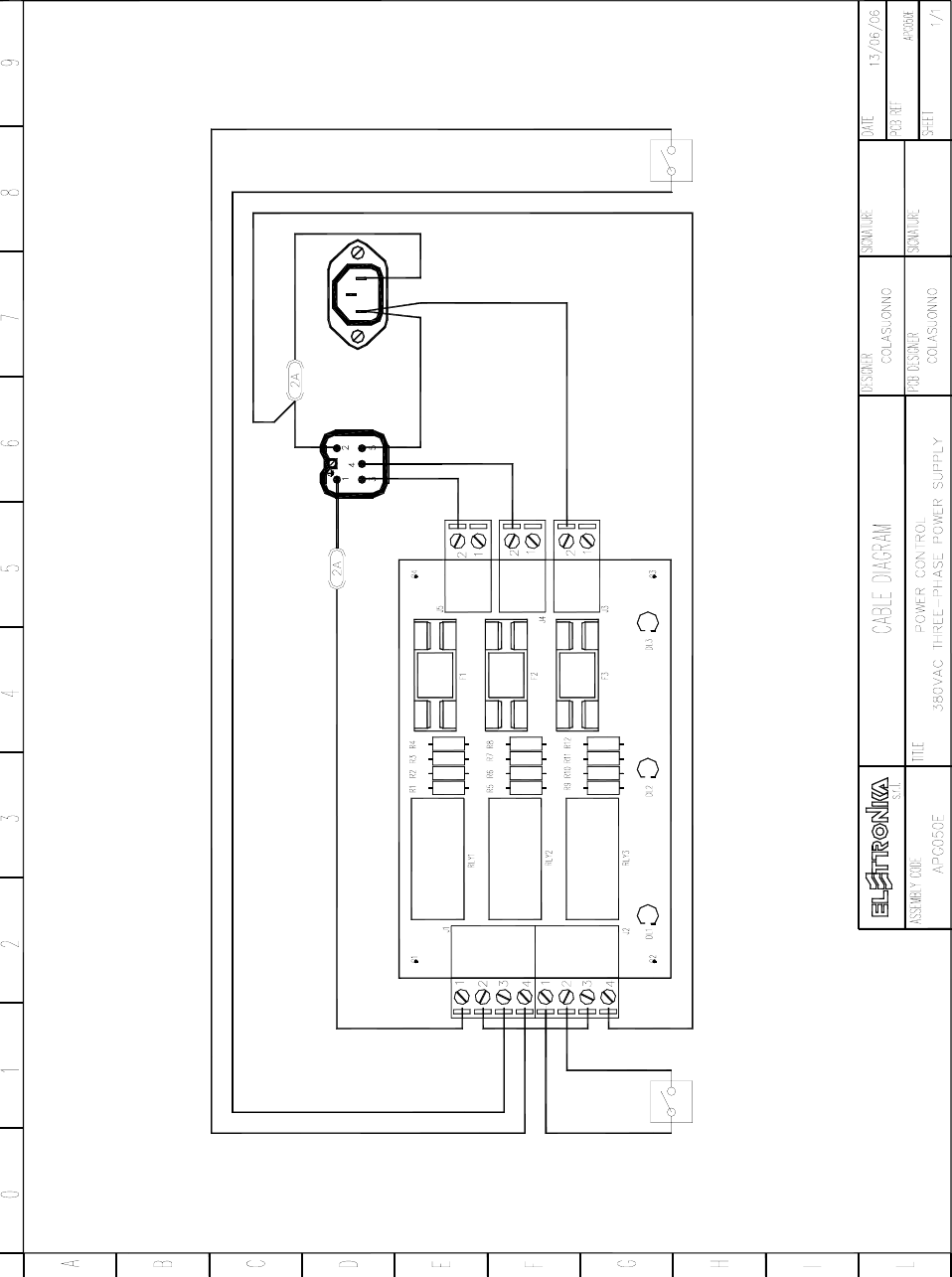
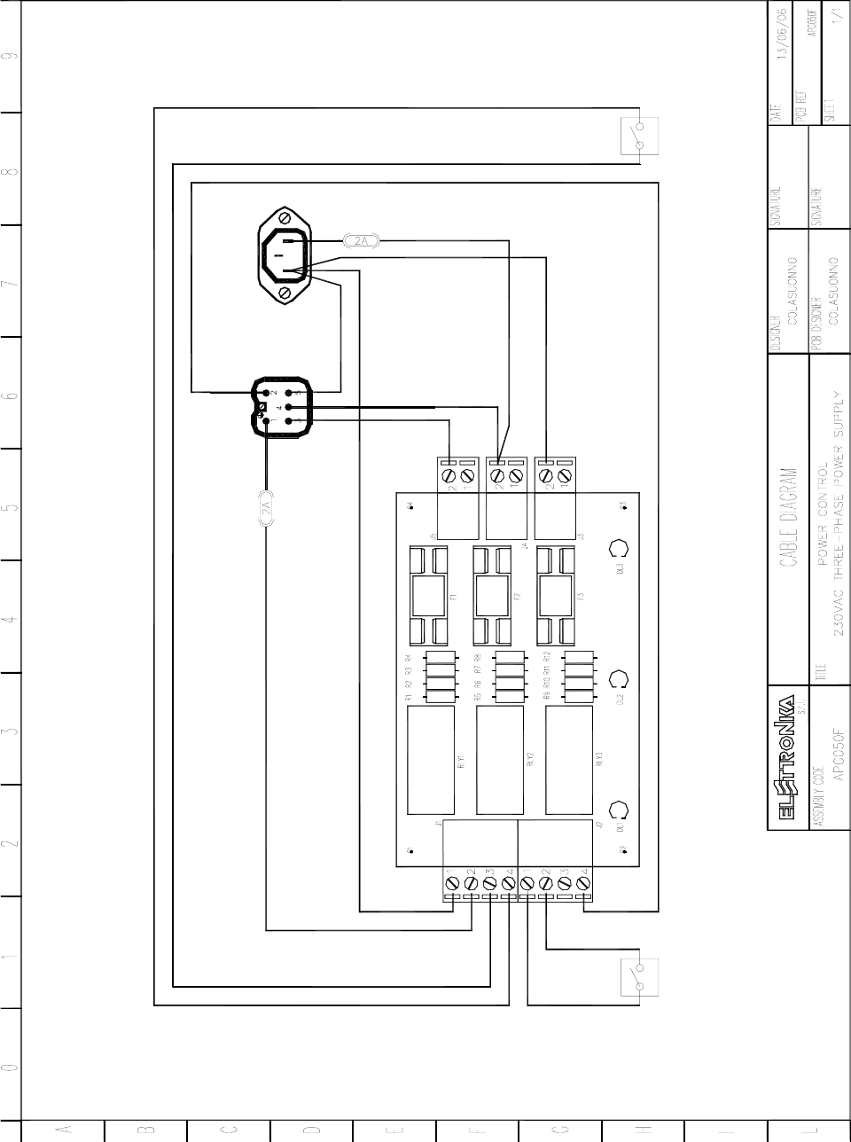
APG050F 230VAC THREE-PHASE POWER CONTROL 1
APT144CM AUTV/1500LD LMOS UHF TV AMPLIFIER 4
C0205 MULTIPOLE CABLE 7.00
C0798 MERLIN PLASTIC TAP 2
CMS6006 1m 1/2” CABLE WITH 7/16” MALE CONNECTOR 4
CMS6009 1.5m 1/2” CABLE WITH 7/16” MALE CONNECTOR 3
CSS5011 N MALE-N MALE CONNECTOR FOR RG58 CABLE 5
DET1069 DET1069R0 BLOCK FOR CONTAINERS WITH WHEELS 11
DET1126 DET1126R0 EIA 1+5/8” RIGID LINE SUPPORT 2
DET1183 DET1183R3 BAR SUPPORT GUIDE 12
DET1184 DET1184R4 ANGOLAR SUPPORT EQUIPMENT 8
Component list APT200B/ATSC

21
DET1201 DET1201R1 ANGOLAR SUPPORT BOX 8
DET1204 DET1204R0 GUIDE SUPPORT 2
DET1205 DET1205R0 GUIDE SUPPORT AMPLIFIER CONTROL 2
DET1283 DET1283R0 BAR SUPPORT BANDPASS FILTER 2
DET1287R2P DET1287R2 DISTRIBUTOR NETWORK COVERAGE 1
DET1288 DET1288R0 SPECIAL SPREADING GUIDE EXCITER 2
DET1294 DET1294R1 GUIDE DIN DISTRIBUTION NETWORK 1
DET1334R0P DET1334R0 FIXING ANGOLAR AC FILTER NETWORK 1
DET1336R0P DET1336R0 FIXING PLATE FILTER NETWORK 1
DET1343R2P DET1343R2 ANGOLAR SUPPORT EQUIPMENT 4
DET1350R0P DET1350R0 DIN GUIDE SUPPORT POWER CONTROL 1
DET1351R0P DET1351R0 SUPPORT NETWORK COVER. DISTRIB. 2
DET1362R2Z DET1362R2 SUPPORT DIRECTIONAL COUPLER 1
DET1367R0P DET1367R0 ANGOLAR SUPPORT EQUIPMENT 2
DET1416R0P DET1416R0 SUPPORT FAN CAPACITOR 1
DET1528R0P DET1528R0 BAR SUPPORT OUTPUT COUPLER 2
DET1529R0P DET1529R0 FIXING DEIAL OUTPUT COUPLER 2
DET1646R0P DET1646R0 CONVEYER 2
FUS04 4A 500V FUSE 2
MTG0143AR0 0.7+0.7+1.4kW UHF DUMMY LOAD 1
MTG0149AR0 4 WAY UHF INPUT DIVIDER 1
PAN0080 PAN0080R0 1U FRONT PANEL 3
PAN0082 PAN0082R0 3U FRONT PANEL 1
SCH0268AR0 FAN CABLE BOARD 1
R0032 PLASTIC BOX FOR DOCUMENTS 1
RAK0006U42 42U OMP RACK 1
V0769 BLACK PLASTIC TAP 1
V0929 TETRAPOLAR TERMINAL 1
V0973 5 POLES AC SOCKET COVER 1
V0974 AC SOCKET COVER 1
V0975 CABLE HEAD 1
V0976 FEMALE CONTACT 5
V0989 4 WAY AC MULTISOCKET 1

22
GND N TSR
1
3
4
2
5
2
54
1
3
21
4
53
1
3
2
54
(Optional)
ATS
EXCITER
AMPLIFIER
APG012C
CONTROL
1 = CONTROL
5 = R
4 = S
2 = N
3 = T
1
246
7A1
A2
8
APD043A
EXCITER
(Optional)
AUTV/1500LD
APT144CM
AUTV/1500LD
APT144CM
AUTV/1500LD
APT144CM
AUTV/1500LD
2 x AXIAL FANS EBM
A2E 250-AM06-13
FANS POWER 1
DRIVER POWER
GND T S R
GROUND BAR
APT144CM
= G
MAINS INPUT
MAINS INPUT
MAINS INPUT
MAINS INPUT
1
2
3 4 56 8
1
2
3
4
5
6
7
FN 256-64-52
MULTIPLE
SOCKET
MAINS FILTER
8
4P 63A/6000MAIN BREAKER
4P 63A/COIL 230VCONTACTOR
4A 500V 28x10mmFUSE
FINDER 81.01TIMER
2P 16A/6000MAIN BREAKER
110/230V GREENLIGHT
2X10A+GSOCKET
7
AUX
MAIN
APG050F
POWER CONTROL
2-5 = L
4-3 = L
1 = NC
= G
2-5 = L
4-3 = L
1 = NC
= G
2-5 = L
4-3 = L
1 = NC
= G
2-5 = L
4-3 = L
1 = NC
53
23
A1
A2
A4
A3
L1
L2
L3
L1 L2
L3
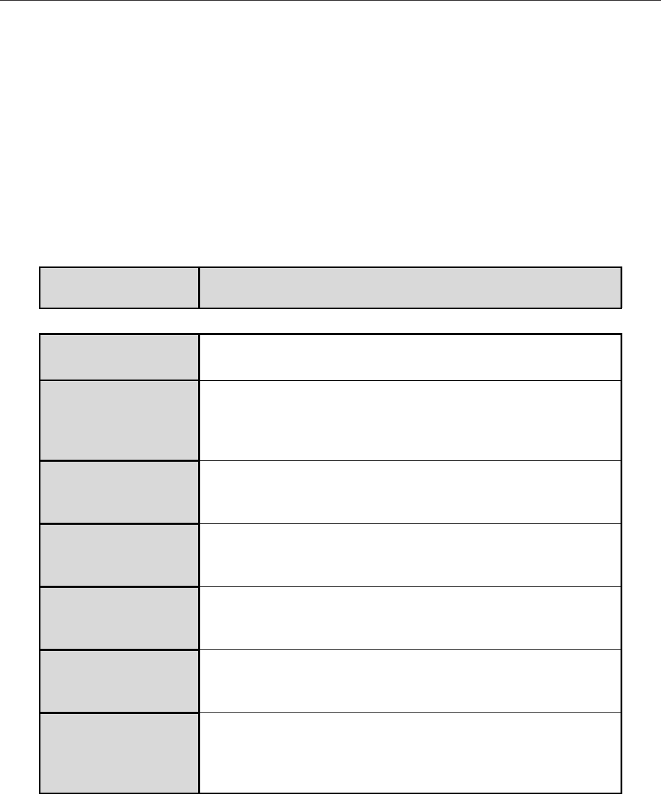
RF OUT
4 WAY HYBRID SPLITTER
470-860MHz
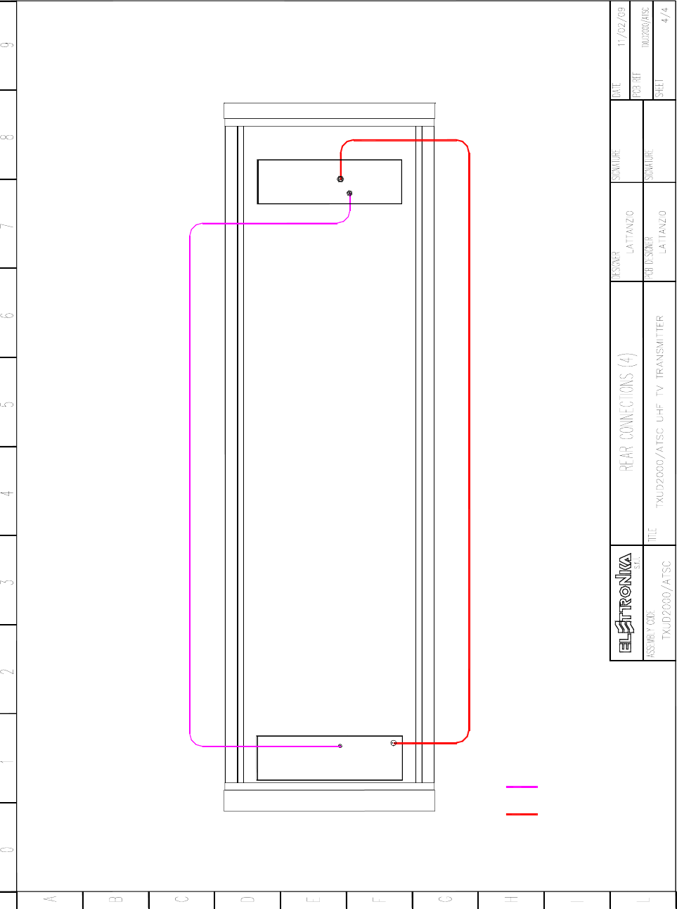
DUMMY LOAD CONNECTIONS
INTERCONNECTIONS CABLE
RF OUT RF IN RF OUT RF OUT
RF INPUT CONNECTIONS
RF OUTPUT CONNECTIONS
24
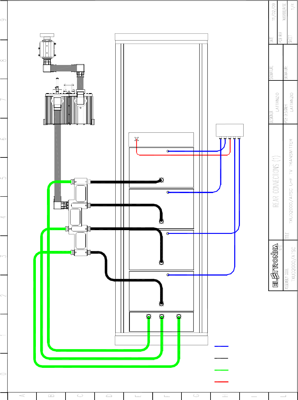
RF MONITOR CONNECTION
RS485 AMPLIFIER CONNECTIONS
FWD AND REF CONNECTIONS
A4
A3
A2
A1
25
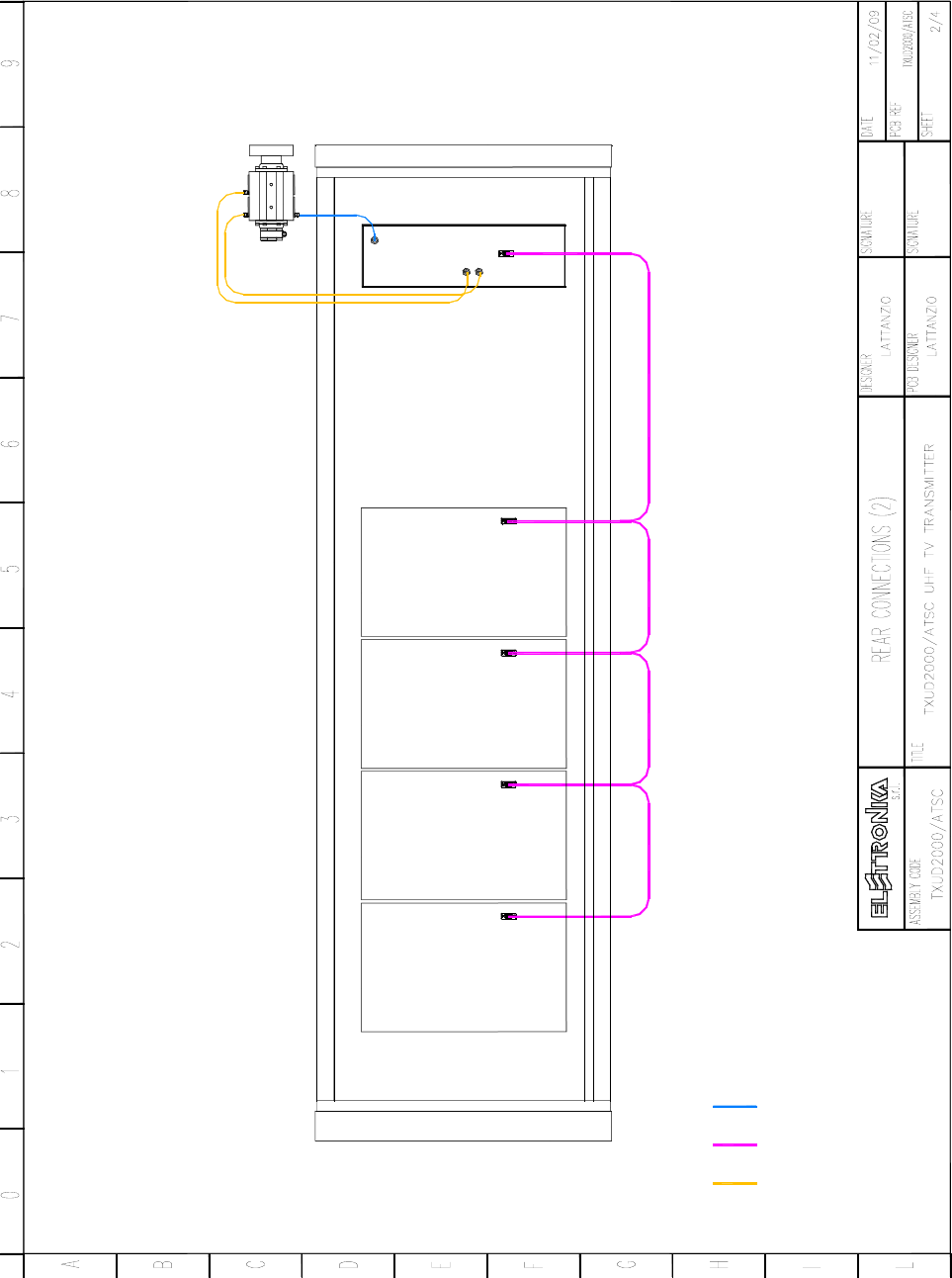
REMOTE CONTROL CONNECTIONS
AGC CONNECTION
26
12
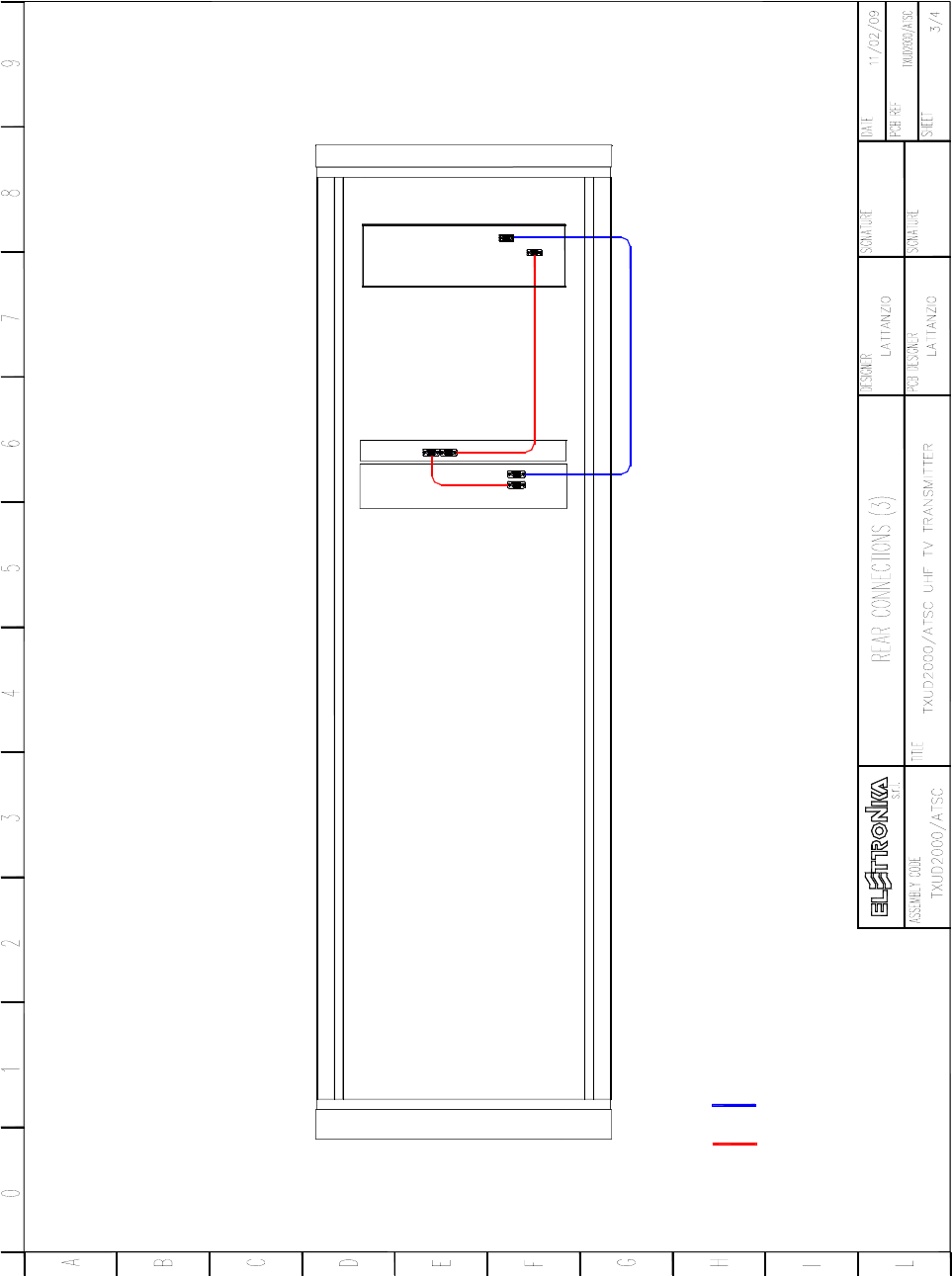
UNBALANCE CONNECTION
24V FAN CONNECTION
27
28
29

30
Elettronika Code Description Qty
00173 68kΩ 1/2W RESISTOR 12
02881 4 POLES MALE CONNECTOR 2
02882A 4 POLES 90° FEMALE CONNECTOR 2
02897 2 WAY MALE CONNECTOR 3
02898 2 WAY 90° FEMALE CONNECTOR 3
03060 5mm GREEN LED 3
07528H 1 POLE 20A 250V MAGNETO-THERMIC SWITCH 1
07541 10A FUSE-HOLDER PANEL MOUNTING 1
07543 FUSE-HOLDER PCB MOUNTING 3
07561B 110V RELE 3
07638 SWITCH 1
07639 EMERGENCY BUTTON 1
CON0311 CON0311R0 COVER 1
CON0312 CON0312R0 MULTISOCKET BOX 1
DET0773 DET0773R0 MECHANICAL DETAIL 1
FUS00012 COVER FUSE 3
FUS2A 2A FUSE 1
PAN0155R2P PAN0155R2P FRONT PANEL 1
PN1286A PN1286AR2 PRINTED CIRCUIT BOARD 1
V0977 AC SOCKET 1
V0978 BOX 1
V0979 MALE CONTACT 5
Z0021 MECHANICAL DETAIL 2
Component list APG050
31
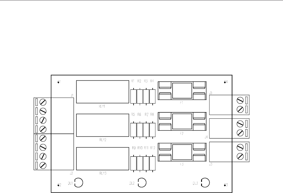
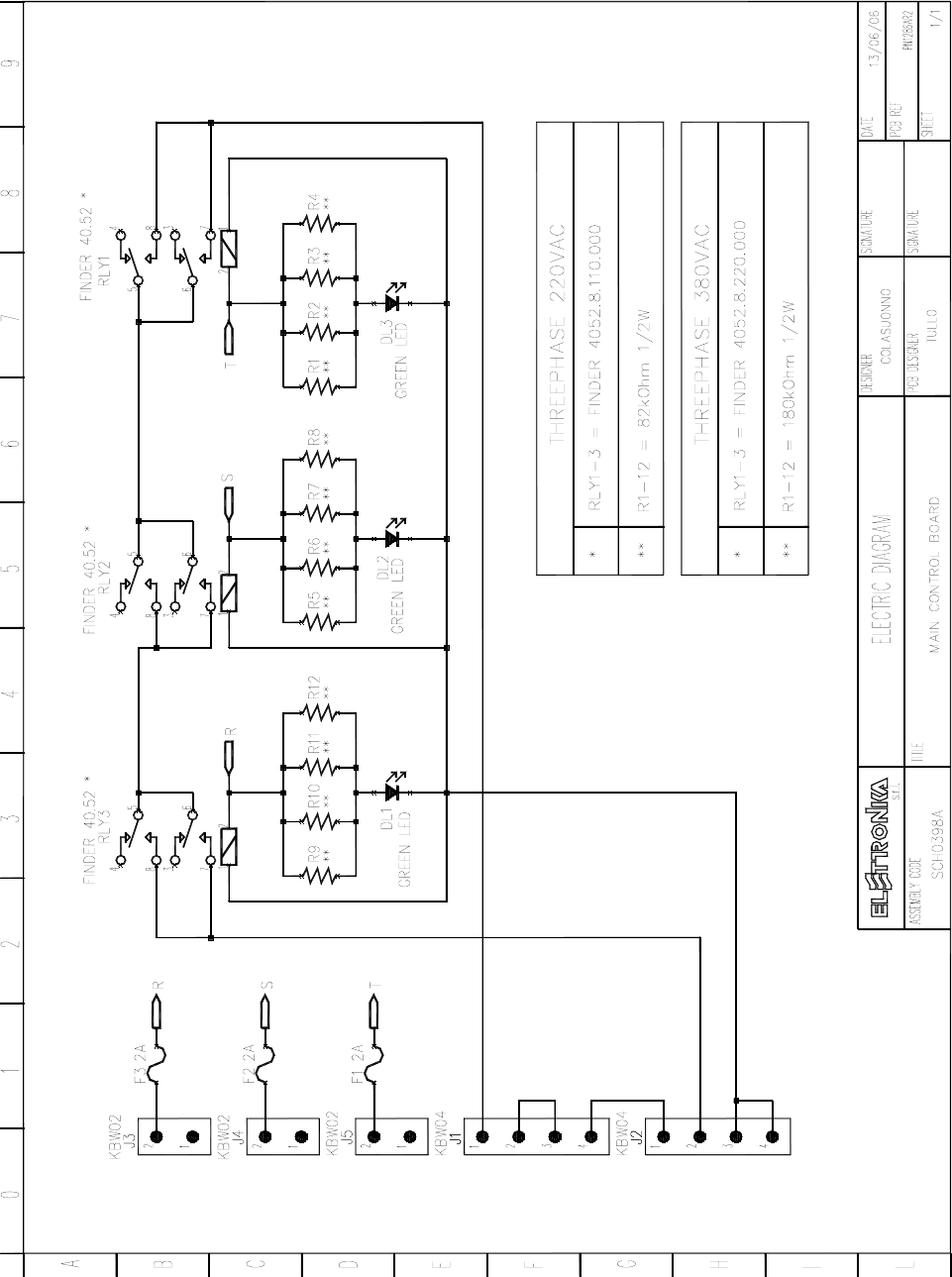
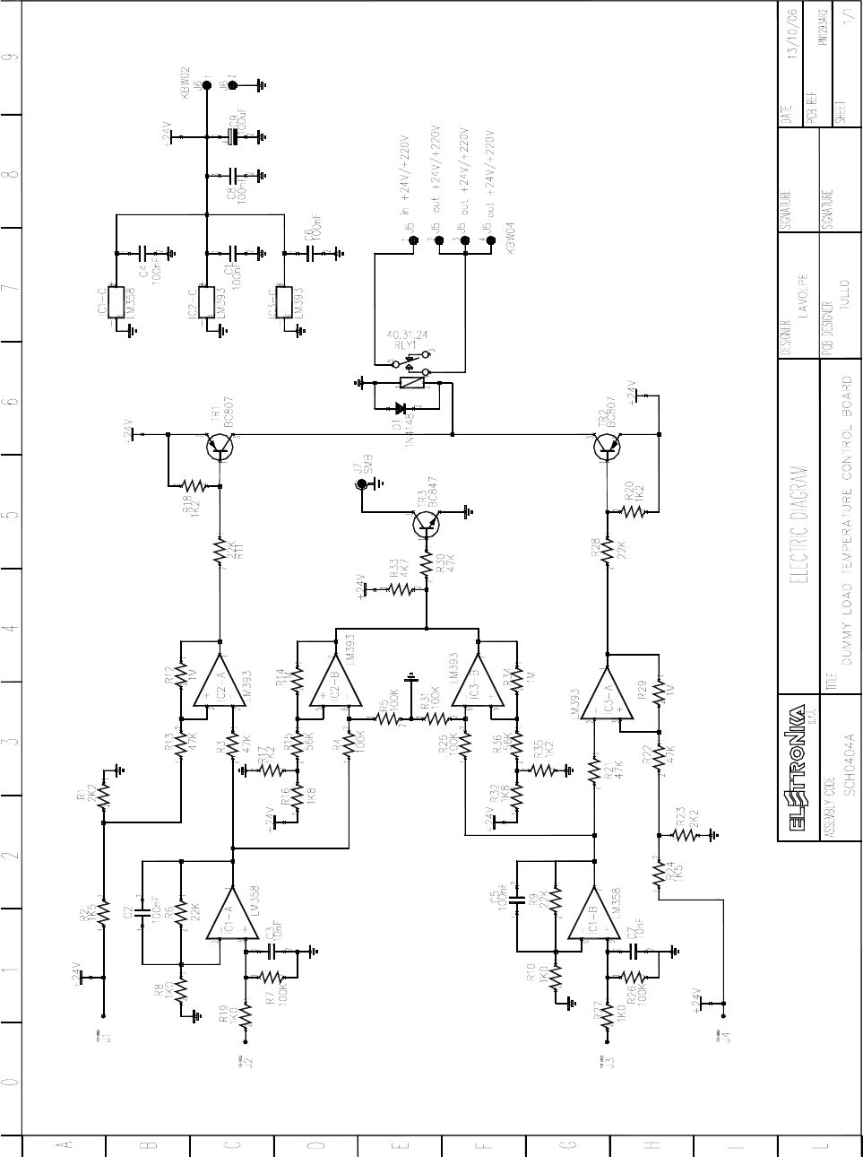
MAIN CONTROL BOARD SCH0398AR0
SCH0398AR0 Component layout
SCH0398AR0 COMPONENT LIST
Part Name/Number Description Qty. Comps.
DL LEDG5 03060 03060 GREEN LED DIODE 5mm 3 DL1-3
FUSE 2A-PCB 7543 7543 5x2 FUSE-HOLDER + FUSE 3 F1-3
J CON KBW02_2P_M_90° 02897 + 02898 ELSAP PCB CONNECTOR 3 J3-5
J CON KBW04_4P_M_90° 02881 + 02882A ELSAP PCB CONNECTOR 2 J1-2
R 100R-1/2W 00139 00139 1/2W 5% RESISTOR 12 R1-12
RL FINDER40.52 756A 7567A RELE 3 RLY1-3
32
33
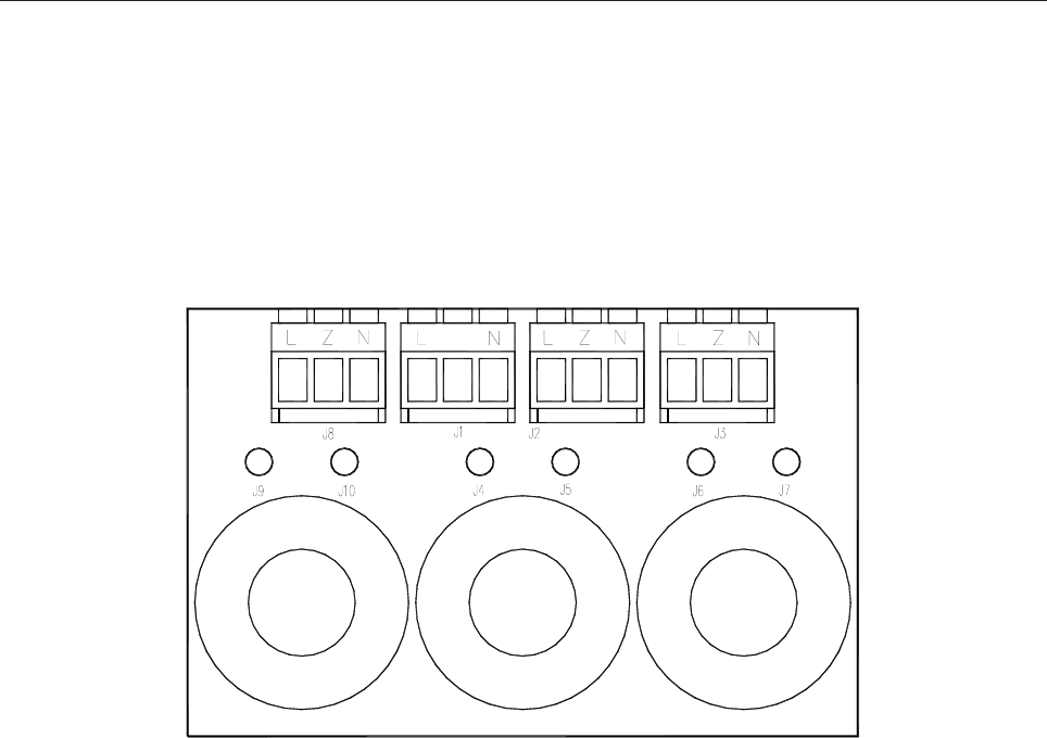
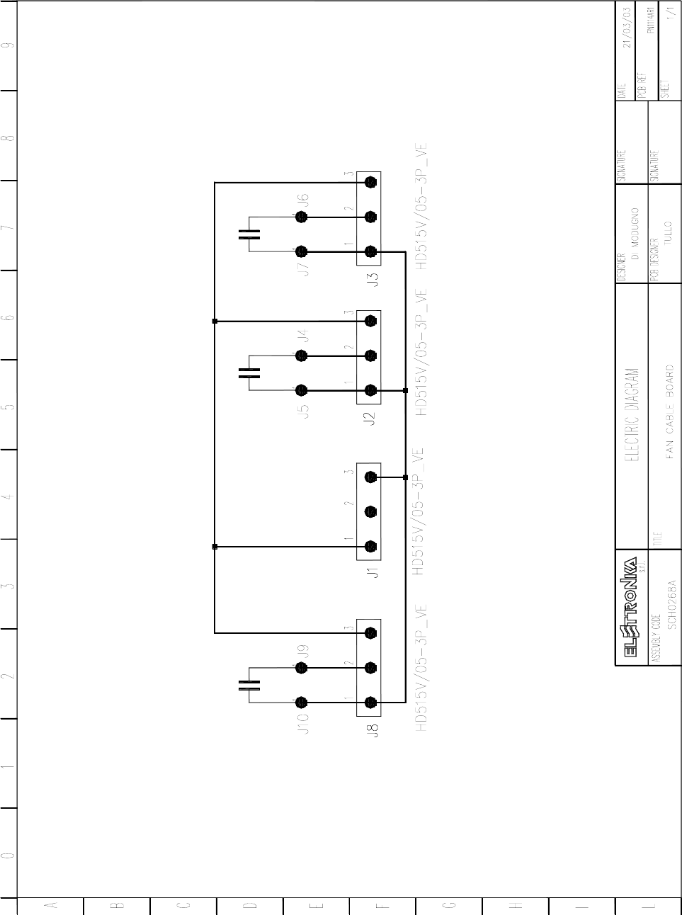
FAN CABLE BOARD SCH0268AR0
SCH0268AR0 Component layout
SCH0268AR0 COMPONENT LIST
Part Name/Number Description Qty. Comps.
J CON HD515V/05-3PVE 02893+02894 PAN PCB CONNECTOR 4 J1-3, J8
J TESTP1.3mm 07913 07913 TEST POINT 6 J4-7, J9-10
34

35
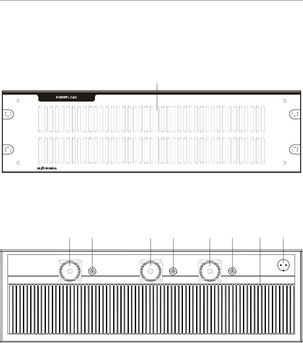
0.7+0.7+1.4kW UHF DUMMY LOAD MTG0143AR0
DESCRIPTION
The MTG0143A module is a load including three unbalancing loads. Two of them can dissipate 700W CW,
the other up to 1400W CW.
The input connector of each load is 7/16” Female. Inside the loads, Florida RF-Labs resistors are used. The
measured Return Loss is higher than 22dB in the band from 450 to 870MHz.
Besides there is an input (BNC Female connector) for each load allowing to monitor the unbalancing power
level on the load. This input is very useful both for testing and while changing channel.
The rear panel of the load module also as other two inputs:
- 2 pin shielded plug to power the SCH0404A board and the fans;
- 4 pin shielded plug used for the serial cabling of the Load modules and the Amplifier Control modules in the
complete device, in order to protect it in case of failure.
The following is a short description of the operation of the module. Next to the resistors there are two
transducers, LM35DT, converting a temperature measure into a control voltage. In case of unbalancing
between the amplifiers, the RF power affects the load and the temperature of the heat sink increases. After a
first higher threshold has been passed, the control voltage, trough the SCH0404A board, enables the fans. In
normal conditions this decreases the temperature of the heat sink until it goes under a lower threshold, then the
control voltage disables the fans.
In case the temperature should rise to about 90°C for any reason, the protection circuit is triggered and
blocks the entire device.
TECHNICAL CHARACTERISTICS
Frequency Range 460 - 870MHz
Max Power 700 - 1400W
Return Loss > 22dB
Powr Supply Voltage +24V
RF Input Impedance 50Ω
36
FRONT PANEL
1
1. Grid
REAR PANEL
1 2 3 4 5 6 78
1. L-1 RF Input Connector 5. L-2 RF Input Connector
2. Test Point 6. Test Point
3. L-3 RF Input Connector 7. 24V Fan Connector
4. Unbalance Connector 8. Grid

37
Component list MTG0143A
Elettronika Code Description Qty
00028A 82Ω 1206 SMD RESISTOR 3
00441 350W 50Ω HIGH POWER TERMINATIONS 8
00664 LM35DT THERMAL SENSOR 2
01041 1nF 50V CERAMIC CAPACITOR 4
01041D 1nF 1206 SMD CAPACITOR 3
01400 BYPASSING CAPACITOR 4
02010 BNC FEMALE CONNECTOR 3
02018 UG909 CONNECTOR FOR RGB174 CABLE 1
02402 7/16” FEMALE CONNECTOR 3
02843 2 POLES SHIELDED SOCKET 1
02518 SMB SOCKET FOR RG174 CABLE 1
03207 HSMS-2802-TR1G DIODE 3
05552B 3-4U HANDLE KIT 2
07586 24V PAPST FAN 3
07596 GRID FAN 3
08500 RG174 50Ω CABLE 0.80
09419 PN419/A PRINTED CIRCUIT BOARD 2
CON0009 CON0009R3 REAR PANEL 1
CON0290 CON0290R0 COVER 2
CON0348R1P CON0348R1P MECHANICAL DETAIL 1
CON0349R1P CON0349R1P MECHANICAL DETAIL 1
DET1054I DET54R1 MECHANICAL DETAIL 2
DET1185 DET1185R1 MECHANICAL DETAIL 2
DET1253 DET1253R2 HEAT SINK 1
DET1254 DET124R2 MECHANICAL DETAIL 1
DET1255 DET1255R1 MECHANICAL DETAIL 2
DET1256 DET1256R1 MECHANICAL DETAIL 1
DET1257 DET1257R2 DUMMY LOAD COVER 1
DET1318R0P DET1318R0P MECHANICAL DETAIL 1
PAN0156R1P PAN0156R1P FRONT PANEL 1
PN1269AR3F PN1269AR3 700W UHF DUMMY LOAD 2
PN1271A PN1271AR3 PRINTED CIRCUIT BOARD 1
PN1273A PN1273AR2 PRINTED CIRCUIT BOARD 1
R0012 18mm DIAMETER WHEEL 8
SCH0404AR1 TEMPERATURE CONTROL BOARD 1
38
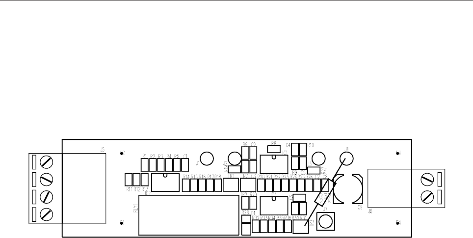
DUMMY LOAD TEMPERATURE CONTROL BOARD SCH0404AR1
SCH0404AR1 Component layout
SCH0404AR1 COMPONENT LIST
Part Name/Number Description Qty. Comps.
CC 100nF-S 01065E 01065E Y5V 0805 CAPACITOR 6 C1-2, C4-5, C7, C9
CC 10nF-S 01053A 01053A SMD 0805 CAPACITOR 2 C3, C6
CE 100uF50V-S 01795A 01795A ELET. SMD CAPACITOR 1 C8
IC LM358M-S 04660 04660 SMD INTEG CIRCUIT 1 IC1
IC LM393-S 04639 04639 SMD INTEG CIRCUIT 2 IC2-3
J CON KBW02_2P_M_90° 02897 + 02898 ELSAP PCB CONNECTOR 1 J6
J CON KBW04_4P_M_90° 02881 + 02882A ELSAP PCB CONNECTOR 1 J5
J SMB-PCB 02516 02516 PCB CONNECTOR 1 J7
J TESTPOINT-P TEST POINT 4 J1-4
R 10K-S 00053C 00053C RES 1/4W 5% SMD 0805 6 R1, R6, R9, R11, R22, R34
R 12K-S 00054C 00054C RES 1/4W 5% SMD 0805 4 R7, R17, R31, R36
R 15K-S 00055C 00055C RES 1/4W 5% SMD 0805 4 R4, R15, R23, R35
R 1K0-S 00041C 00041C RES 1/4W 5% SMD 0805 2 R19, R33
R 1K8-SS 00044B RES 1/4W 5% SMD 0805 4 R2, R8, R24, R27
R 1M-SS 00077B RES 1/4W 5% SMD 0805 4 R14, R16, R29-30
R 220R-SS 00033D RES 1/4W 5% SMD 0805 2 R20-21
R 2K0-SS 00004 RES 1/8W 1% SMD 0805 2 R10, R12
R 47K-S 00061C 00061C RES 1/4W 5% SMD 0805 2 R18, R32
R 4K7-S 00049C 00049C RES 1/4W 5% SMD 0805 2 R13, R28
R 5K6-S 00050C 00050C RES 1/4W 5% SMD 0805 4 R3, R5, R25-26
RL 40.31.24 7567C RELE 1 RLY1
TR BC807 03453 03453 PNP SMD TRANSISTOR 2 TR1-2
39
40
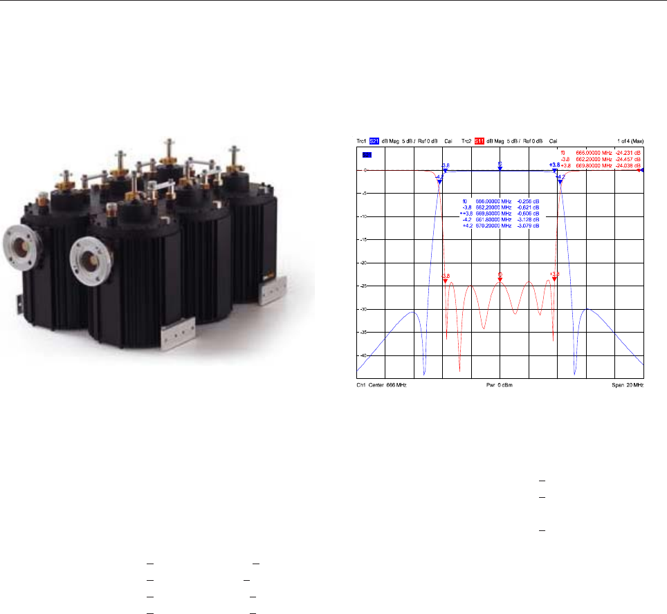
UHF DTV BANDPASS FILTER 06655A
TECHNICAL DATA
Frequency Range 470 - 862MHz SWR < 1.22
Configuration 6 Cavities elliptical 2nd Harmonic Attenuation > 80dB
Bandwidth 6 to 8MHz Group Delay Variation < 250ns
Max Output Power 2.5kW (rms) Temperature Stability < 1.5kHz / K
Insertion Loss f(0) < 0.3dB Ambient Temperature Range -10° to +50°C
Attenuation f(0) ±3.8MHz < 0.8dB (SWR 1.22), < 1dB (SWR 1.18) Weight 35kg
Attenuation f(0) ±4.2MHz > 5dB (SWR 1.22), > 6dB (SWR 1.18) Working Position Any
Attenuation f(0) ±6MHz > 30dB (SWR 1.22), > 35dB (SWR 1.18) Dimensions Max 370 x 372 x 564mm
Attenuation f(0) ±8MHz > 45dB (SWR 1.22), > 50dB (SWR 1.18) Output Connector EIA 1+5/8” Unflanged
TUNING INSTRUCTIONS
To calibrate the filter PBN153/45-6C/58, a double-track Network Analyser is needed, in order to display
the frequency response of the passing signal and the reflected one. The filter is composed by siz band-pass
cavities with coupling between intermediate cavities.
Connect the filter to the Network Analyser, marking the input. Select the middle frequency of the channel
range in the middle of the screen and set a SPAN of 50MHz.
Turn the coupling (4) (fig. 1) to the end.
Act on the tuning rods (1) (fig. 1) until the curve is displayed at the center of the screen, then act on the
interstage couplings (2) and on the IN/OUT couplings by rotating the screw (3) to obtain a band width of
about 8MHz.
Set the instrument for a SPAN of 20MHz, move the markers to the limits of the used band (Fo ±3.9MHz).
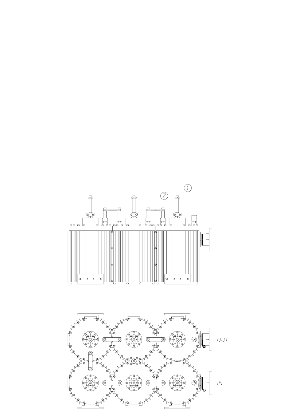
41
Rotate the coupling (4) (fig. 1) until the notch attenuations appear and are positioned at about ±6MHz
from the centre of the channel.
Alternately proceed with all adjustments, taking into consideration that each time the IN/OUT couplings
(3), the nearer tuning to the relevant coupling and the relevant interstage coupling must be shifted.
Once an adaptation over 25dB has been obtained, included between the two markers at the limits of the
band in use, lock the fastrening handle (4) compensating the locking rotation (anticipating it).
Fasten the couplings (2).
Fasten the tunings by means of a 10mm wrench, compensating each time the mechanical adjustment of
each.
Example of tuning in CH 31 Standard B 8MHz.
42
43
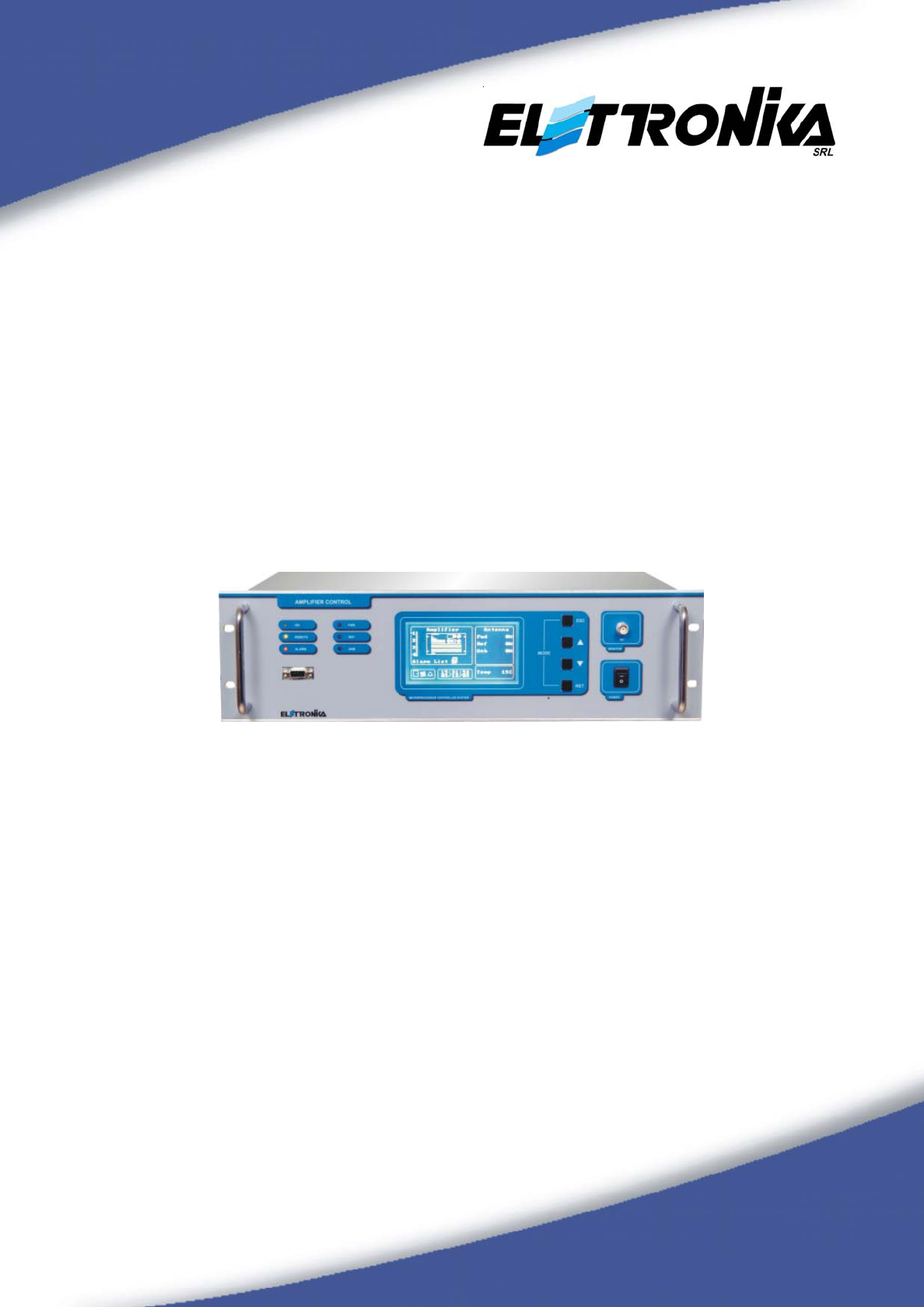
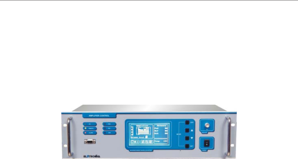
AMPLIFIER CONTROL
User’s manual
ACCESSORIES

44
This page is intentionally blank

45
Section 1 - Information
Contents:
1.1 Description
1.2 Technical characteristics
Front panel
Rear panel
Front and rear panel connectors
Block Diagram
46
1.1 DESCRIPTION
The Amplifier Control (AC) module is the equipment that allows to monitor and manage from a single location
a modular transmitter, composed by several combined amplifier modules (AM). The AC continuously monitors
the status of the AMs and highlights any anomaly, it monitors the powers in antenna (forward and reflected)
and the unbalancing, if any, showing all of the parameters on the display and through the status LEDs. It is
possible to power supply the fans of the rack directly by the AC, which constantly monitors their operation,
thus protecting the AMs and the other components in the rack in case of failure. Even the exciter(s) can be
powered directly by the AC, so that it can be switched on or off along with the amplification stage.
The human-machine interface (HMI), intuitive and user-friendly - most of all thanks to the large graphic
display which covers the most of the front panel and to the six status LEDs -, the noise-immune RS485
connection with the AMs, the possibility to connect a series of switches to an Interlock input and the remote
control option make the AC a reliable, as well as easy to use, device to be used in low and high-power, FM
and TV, analogue and digital, combined and separated transmitters.
In most cases the AC is already installed into the transmitter, wired and calibrated, so that the user can use it
without having to worry about technical details. Anyway, Section 2 of this manual covers the main information
about installation and external connections. For additional technical information, contact the Customer Service
of Elettronika S.r.l. or the local distributor. Section 3 describes the operation of the AC and everything the
user can do with it. Read this section carefully before using the device.
AMPLIFIER CONTROL

47
1.2 TECHNICAL CHARACTERISTICS
Human-Machine Interface
- 240x128 graphic display with CCFL backlight
- 3 general LEDs (ON, REMOTE, ALARM)
- 3 alarm LEDs for RF powers (FWD, REF, UNB)
- 4 push-buttons (ESC, RET, UP, DOWN)
Alarms resulting in the transmitter being switched off
- Fans rotation (about 10 second delay)
- Interlock (immediate, can be disabled)
- Antenna Reflected power (if configured)
Alarms not resulting in the transmitter being switched off
- Lack of communication with an Amplifier Module
- Amplifier module locally switched off
- Alarm on amplifier module
- Power in antenna or unbalancing beyond the threshold (Reflected power alarm can be configured to switch off the trans-
mitter)
Connections on the front panel
- RF Monitor on 50Ω BNC connector (0dBm at the nominal power)
- RS232 on DCE-type D-SUB9 female connector, for control via PC or firmware update
Connections on rear panel
- RS485 on two D-SUB9 female connectors for the connection with the Amplifier Modules
- RS485 on D-SUB9 female connector for the connection with an optional remote control device*
- Telemeasures (Forward power, Reflected power, Unbalancing, Alarm) and telecontrol (ON/OFF) on D-SUB25 female connector
- Up to 8 RF powers can be monitored on BNC connectors
- Fans rotation control on BNC connector
- Alarm on the opening of a series of switches (Interlock) on BNC connector
- Power supply +24Vdc available on two 2-poles connectors
Miscellaneous
- Real-time clock with CR2032 lithium backup battery (nominal voltage 3V, nominal capacity 210mAh)
- Alarm and event list up to 130 entries
- 100-240Vac 50/60Hz Power Supply
- 19”-3U Cabinet, deep 260mm
- 6kg Weight
- Operating Temperature -5° to +45°C
- Relative Humidity 20% - 90%
- Altitude up to 2500m
* For more information contact the Sales Department of Elettronika S.r.l. or the local distributor.
Specifications and characteristics are subject to change without notice.
48
POWER
MICROPROCESSOR CONTROLLED SYSTEM
RS232
AMPLIFIER CONTROL
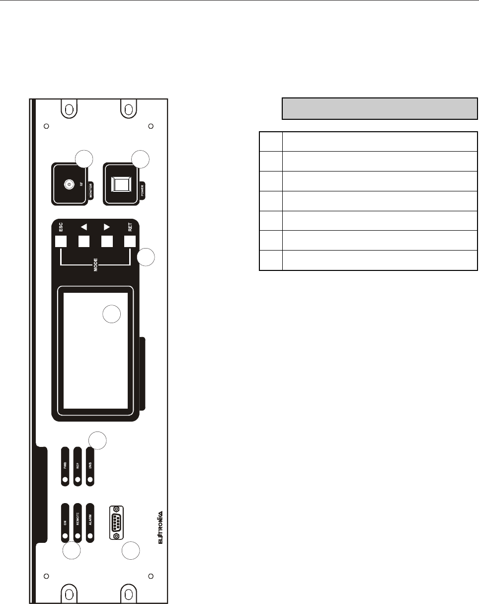
Front panel
1
3
4
5
6
7
2
DESCRIPTION
1 Status LEDs
2 Alarm LEDs
3 RS232 Socket
4 LCD Display
5 Function Keys
6 RF Monitor Connector
7 Main Switch
49
21
RS485 AMPL INTERLOCKRS485 REMOTE
GND
ABCDEFGH
AGC TELEMEASURES
FANS CONTROL24Vdc
A
FUSE
FANS1 POWERFANS2 POWERDRIVER POWER
MAIN POWER SUPPLY
RF MONITOR IN
FUSE
A
A
FUSE
21
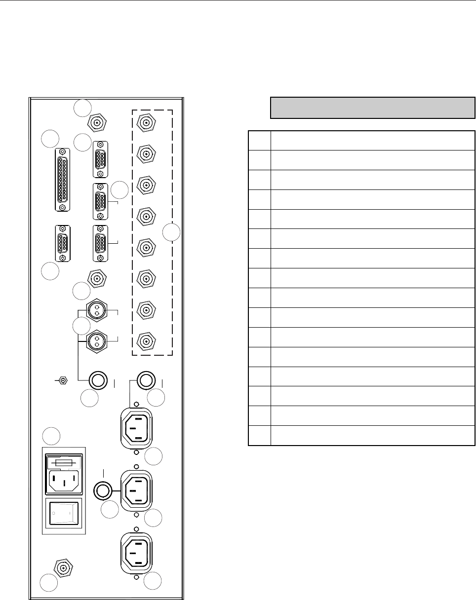
Rear panel
12
345
6
7
9
10
13
14 15
11
12
16
DESCRIPTION
1 RF Monitor Input Connector
2 Main Power Supply Socket with Fuse (10A)
3 Driver1 Power Supply Socket
4 Driver2 Power Supply Socket
5 Fans Power Supply Socket
6 1A Fuse (+24Vdc)
7 Fuse (Fans: the value may change)
8 Fuse (Fans: the value may change)*
9 +24Vdc Connector
10 AGC Socket
11 Telemeasure Socket
12 Fans Control Connector
13 RS485 Amplifiers Socket
14 RS485 Remote Control Socket
15 Interlock Connector
16 Power Measurement Connector
8
* Present only in two racks transmitter
50
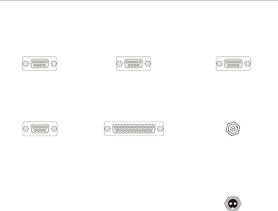
Telemeasures (on rear panel)
Pin 1: Remote ON/OFF TTL Input
GND=Remote ON
+5V or float=Remote OFF
Pin 6: Alarm TTL Output
GND=Alarm
+5V=no Alarm
Pin 7: RMS/PEAK Power TTL Input
GND=RMS
+5V or float=PEAK
Pin 8: GND
Pin 9: GND
Pin 14: Remote Amplifier ON/OFF TTL Input
if Remote ON then
GND=Amplifier OFF
+5V or float=Amplifier ON
Pin 19: Alarm TTL Output
GND=Alarm
+5V=no Alarm
Pin 20: GND
Pin 21: +5V
Pin 22: Forward Power
Analog Output (0V - 5V)
Pin 23: Refleted Power
Analog Output (0V - 5V)
Pin 24: Unbalance Power
Analog Output (0V - 5V)
Remote RS485 for RCU connection
(on rear panel)
Pin 2: RS485 RX- Pin 7: RS485 TX-
Pin 3: RS485 RX+ Pin 8: RS485 TX+
Pin 5: GND
AGC (on rear panel)
Pin 1: GND
Pin 2: AGC Alarm TTL Output
GND=AGC Alarm
+5V=no AGC Alarm
Pin 3: AGC Alarm TTL Output
GND=AGC Alarm
+5V=no AGC Alarm
Pin 8: Forward Power
Analog Output (0V - 5V)
Pin 9: Forward Power
Analog Output (0V - 5V)
Fans Control (on rear panel)
Contact: Fans Control Switch
TTL or Free contact Input
Closed/GND=no Fans Alarm
Open/+5V=Fans Alarm
Body: GND
RS485 Amplifiers
(on rear panel)
Pin 2: RS485 TX- Pin 7: RS485 RX-
Pin 3: RS485 TX+ Pin 8: RS485 RX+
Pin 5: GND
+24Vdc Output (on rear panel)
Pin 1: GND Pin 2: +24Vdc Out
(for Dummy Load)
21
Front and rear panel connectors
RS232 (on front panel)
Pin 2: RS232 TX Pin 5: GND
Pin 3: RS232 RX
51
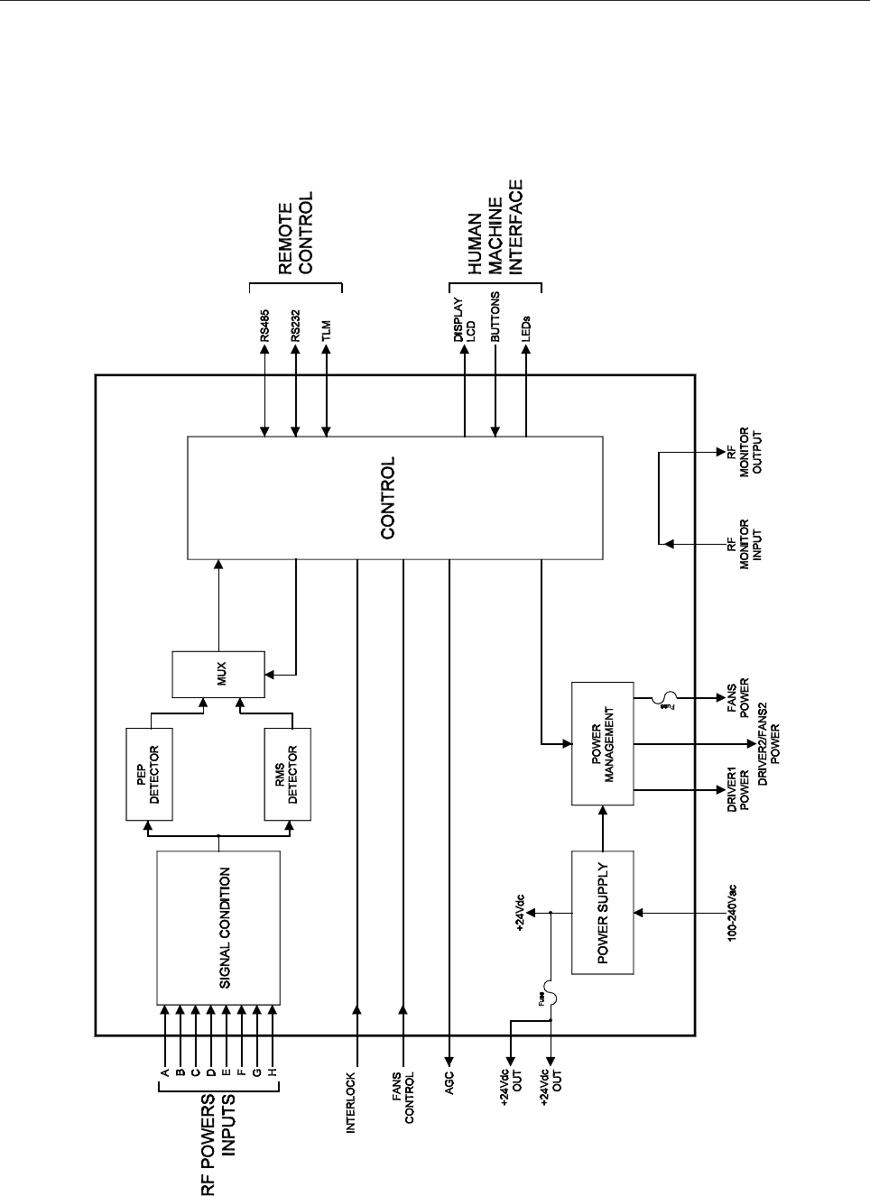
Block diagram

52
This page is intentionally blank

53
Section 2 - Installation
Contents:
2.1 Preliminary operations
2.2 Operating environment
2.3 First installation
2.4 Connection with a Remote Control System
54
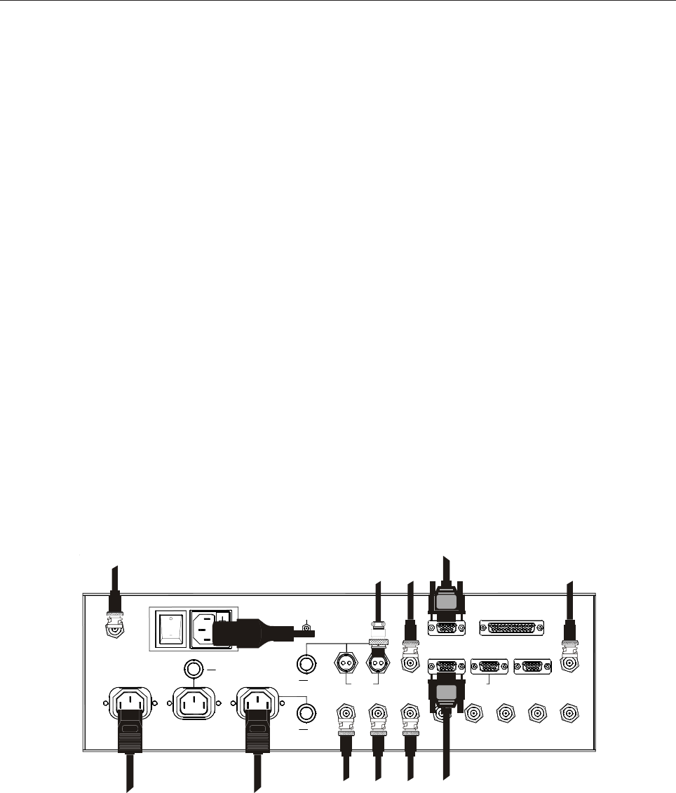
2.1 PRELIMINARY OPERATIONS
No wiring is necessary because the device is already installed and correctly connected to the power supply
and other parts of the transmitter. In case a new AC has to be installed, check all connections with the help of
the diagrams and tables in this Section. Correct installation of the equipment is important for maximum
performance and reliability. Before switching on and powering the transmitter, make sure that all connections
are correctly made.
The pinout tables of multi-pin connectors can be found in the Front and Rear Panel in the previous Section.
2.2 OPERATING ENVIRONMENT
The equipment can be installed into a standard component rack or on a suitable surface such as a bench or a
desk. In any case, the area should be as clean and well-ventilated as possible. Always allow for at least 2cm
of clearance under the unit for ventilation. If the device is set on a flat surface, install spacers on the bottom
cover plate. If it is installed in a rack, provide adequate clearance above and below. Do not locate the device
directly above a heat source.
2.3 FIRST INSTALLATION
Main Power Supply
Before connecting the power supply cable, make sure that two 10A fuses have been put inside the socket. To
open it, use a little screwdriver to move the plastic table. Then connect the power supply cable. To switch on
the amplifier control, move the switch next to the power supply connector to position 1.
21
RS485 AMPL INTERLOCKRS485 REMOTE
GND
ABCDEFGH
AGC TELEMEASURES
FANS CONTROL24Vdc
A
FUSE
FANS1 POWERFANS2 POWERDRIVER POWER
MAIN POWER SUPPLY
RF MONITOR IN
FUSE
A
A
FUSE
21
AC POWER
DRIVER
POWER SUPPLY FANS
POWER SUPPLY
FWD UNBREF
RF MONITOR INPUT
RS485
AMPLIFIERS
DUMMY LOAD

55
DRIVER1/2 Power Supply
The transmitter can be wired so that the exciters are directly fed by the AC. The advantage of this configuration
is the possibility to control the whole transmitter, Amplifier Modules and drivers, from a single point, that is the
AC. Using the adequate male-female cord, connect the power supply of the driver to DRIVER1 POWER
connector, for combined transmitters; connect the power supply of the drivers to DRIVER1 POWER and
DRIVER2 POWER connector, for TV separated transmitter.
FANS Power Supply
The rack in which the transmitter is installed is usually provided with cooling fans. These can be fed directly by
the AC in the same way as the drivers, so that they are automatically switched on and off along with the AMs.
To do this, connect the fans to the FANS POWER connector using the proper cord. The power supply is
limited by a fuse on the rear panel. The blowing current of this fuse depends on the kind of fans in use.
FANS CONTROL
A failure of fans may cause the temperature of the rack to rise beyond acceptable limits, with dangerous
consequences on the most critical parts of the AMs. For this reason, the AC continuously monitor the rotation
of the fan, if it is powered, by analysing the input signal at the FANS CONTROL BNC connector. If the fans
are rotating, the two poles of the BNC connector should be shorted.
INTERLOCK
The Interlock connector may be used as an additional alarm source stopping the transmitter operation. Usually
it is connected to the frame of the rack and activated when it is open, in order to prevent the operators to
touch dangerous electrical parts during maintenance operations. It is possible to connect a series of switches
between the two poles of the BNC Interlock connector: during normal operations all switches are closed, if
any of them is open, the AC detects the absence of continuity between the two poles of the INTERLOCK
connector and immediately stops the transmitter. Anyhow, this behaviour can be disabled from the display.
RF Powers (A-H)
During the normal operation of the transmitter, the AC measures the RF powers in antenna (forward and
reflected) and the unbalancing, if any, at the combiners. A maximum of 8 inputs is possible, even though usually
only 3 of them are used (1 forward power, 1 reflected power, 1 combiner unbalancing). That depends on the
kind of transmitter. Usually channel A is used for forward power, channel B for reflected power, channel C for
the unbalancing.
AGC
In some transmitters it is possible to implement the AGC (Automatic Gain Control) functionality, which allows
to keep the power output in antenna constant in spite of any factor which may make it changes, such as
temperature. To implement the AGC functionality correctly, the exciter (or exciters for dual driver transmitters)
has to be connected to the AC using the cable provided.
When this connection is present and the AGC is enabled on the exciter, the latter can read the power in
56
antenna and keep it constant over time, by increasing or decreasing the internal gain. In case of faults in the
high-power amplifier stage, the AC stops the AGC in order to prevent any possible damage.
AMPL RS485
In a high-power transmitter there are a number of Amplifier Modules (AM) which RF outputs are combined
in order to provide the required total high power. Although these are separated devices, it is necessary to be
able to control all of them from a single point of the transmitter, and even switch them on and off at the same
time. This point is represented by the AC, which is in constant communication with all AMs through an RS485
serial bus, immune from electromagnetic noise inside the rack of the transmitter. All AMs have to be connected
to the AC by using the proper multi-connector cable to one of the two AMPL RS485 connectors.
+24Vdc
On the rear panel there are two two-poles connectors on which a +24V DC power supply is always available,
protected by a 1A fuse. It is usually used to power supply Dummy Loads in the rack.
RF Monitor
On the front panel of the AC there is a monitor of the RF signal in antenna on a 50Ω BNC connector. The
technical staff of Elettronika provides for the correct calibration of this monitor, taking into consideration the
coupling of the directional coupler and all cable losses, if any. At the nominal power of the transmitter, the
signal level at the RF monitor is 0dBm level.
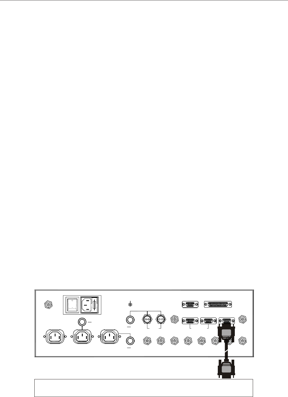
2.4 CONNECTION WITH A REMOTE CONTROL SYSTEM
The AC can be controlled locally by the display and buttons or remotely by using one of the following three
systems: RS485, Telemeasures or RS232 (only one at a time).
REMOTE CONTROL UNIT
PORT n
21
RS485 AMPL INTERLOCKRS485 REMOTE
GND
ABCDEFGH
AGC TELEMEASURES
FANS CONTROL24Vdc
A
FUSE
FANS1 POWERFANS2 POWERDRIVER POWER
MAIN POWER SUPPLY
RF MONITOR IN
FUSE
A
A
FUSE
21
57
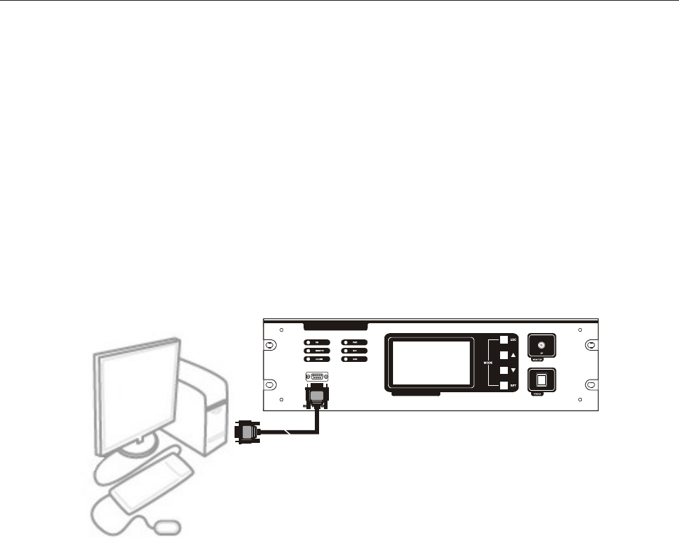
RS232
On the front panel of the AC there is a D-SUB9 female connector used to control the transmitter from a PC,
using a standard RS232 serial connection. For more information about remote control option, contact the
Sales Department of Elettronika S.r.l. or the local distributor.
The pin-out of this connector is DCE-type and can be connected to a PC using a direct cable.
This connector can also be used to update the firmware of the AC. This operation should only be performed
by qualified technicians.
RS485
On the rear panel there is a D-SUB9 female connector used for remote control via RS485. The RCU device
manufactured by Elettronika S.r.l. is needed for this feature to be used. For more information, contact the
Sales Department of Elettronika S.r.l. or the local distributor.
Telemeasures
The D-SUB25 female connector allows to control the transmitter remotely using a generic control interface.
Some analogue and digital outputs are available on this connector, thanks to which a control system can read
the status of the transmitter. There are also some inputs allowing to switch the transmitter on and off from
remote by opening or closing some contacts.
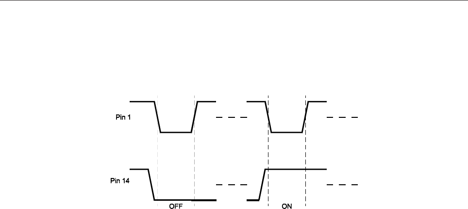
It is possible to connect two switches to close pin 1 and pin 14 to GND. Usually the switch on pin 1 is open
in order to disable remote control. To switch the transmitter on/off, close/open the switch on pin 14 depending
on the command to be given, then close the switch on pin 1 to send the command. Once it has been received
by the AC, the switch on pin 1 can be open again. For better comprehension see the figure below, showing the
closed switch with a low level and the open one with a high level.
POWER
MICROPROCESSOR CONTROLLED SYSTEM
RS232
AMPLIFIER CONTROL
SERIAL PORT
58
Switching on and off the transmitter by means of two switches on pins 1 and 14 of the telemeasures connector

59
Section 3 - Operations
Contents:
3.1 Switching On the Amplifier Control
3.2 Operation
3.3 Menu

60
3.1 SWITCHING ON THE AMPLIFIER CONTROL
After having made sure of the wiring, the transmitter can be switched on by using the mains switch on the rear
panel. The very first time the transmitter is switched on, set the POWER button on the front panel to 0, which
means transmitter off. The display will show for a few seconds an introduction animation, displaying the kind
of transmitter and the firmware version. During this stage, all LEDs light up and the buzzer sounds in order to
check that it works. Since both LEDs and buzzer are used to signal failures, it is important to check them
periodically. Check the paragraph dedicated to the display, later in this manual, in case it should be hard or
impossible to read.
3.2 OPERATION
The Amplifier Control (AC) is the central point of the whole transmitter. It allows to switch on and off all of the
amplifier modules (AM), the exciters and the fans, it monitors alarms and anomalies and automatically applies
any precaution needed, it manages the user interface by means of the display, LEDs and buttons and answers
to local or remote commands by the user.
There are two main operating statuses of the transmitter, ON and OFF, both described in detail below.
OFF Status
In the OFF status the output power in antenna is zero. To switch off the transmitter locally, just set the
POWER button on the front panel to 0. The ON LED is switched off as well. While the POWER button is set
to 1, it is still possible to switch off the transmitter from remote, if this function is enabled, through the RS232/
RS485 serial connections or the TELEMEASURE connector. In this case the ON LED starts blinking.
In OFF status, the AC stops feeding the fans and the exciters, switching them off, and also puts in stand-by all
of the AMs. While in OFF status the AC keeps communicating with the AMs, polling their data and showing
them on the display. Usually, in this situation, most of these parameters are null.
ON Status
The ON status indicates the normal operation of the transmitter, which is switched on and is sending power to
the antenna. To activate this status, just set the POWER button on the front panel to 1, or use the remote
RS232/RS485 serial connection or the TELEMEASURE connector. It is possible to switch on the transmitter
from remote only if this function has been enabled and the POWER button is on position 1. While in ON
status, the ON LED is lit. When changing to ON status, the AC feeds the exciters and the fans and switches
on all of the AMs. While in this status it polls all data from the AMs and shows them on the display. It also
monitors the status of the fans, the Interlock and the RF powers.
Interlock
In case of Interlock alarm, if it is enabled, the AC immediately switches off the transmitter (AMs, fans and
61
exciters). If the alarm ends, the transmitter is automatically switched on again.
Fan Control
In case of fan alarm, that is when the FANS CONTROL shows that they are not working properly, the AC
switches off the AMs and exciter(s) after a few seconds, but keeps the fans on, unlike the Interlock alarm. If
the alarm was due to a temporary block or failure and the fans restarts working, the AC automatically switches
on the AMs and exciter(s) again.
RF Powers
The AC continuously monitors the value of the RF powers in antenna and of the unbalancing, and shows them
on the display. Each power has a maximum threshold which is set in factory depending on the type of transmitter.
If any of this power goes beyond this threshold, the AC indicates an alarm condition by means of the LEDs
and buzzer, and by blinking the indication of the power on the display.
The transmitter is not switched off in this case, because the AMs are protected against excessive power
values. It is possible to enable the REF protection that causes the switching off when the reflected power in
antenna is too high.
LEDs
On the front panel there are six status LEDs which allow a visual verification of the status of the transmitter.
The three LEDs on the left (ON, REMOTE and ALARM) are general ones; the three on the right (FWD,
REF and UNB) refer to the alarms concerning RF powers. Table below shows the meaning of each LED.
LED COLOUR OFF ON BLINKING
ON Green Transmitter Off Transmitter On Transmitter Off by remote
REMOTE Yellow Remote control disabled Remote control enabled -
ALARM Red No alarm present Alarm present Alarm ended
FWD Red Forward power
under the threshold -Forward power
beyond the threshold
REF Red Reflected power
under the threshold -Reflected power
beyond the threshold
UNB Red All of Unbalancing
under the threshold -One of Unbalancing
beyond the threshold
3.3 MENU
During normal operation, all information gathered by the AC (RF powers, parameters of the AMs, temperature,
date, time, etc) are displayed on a large 240x128 graphic display provided with backlight. If this display is
62
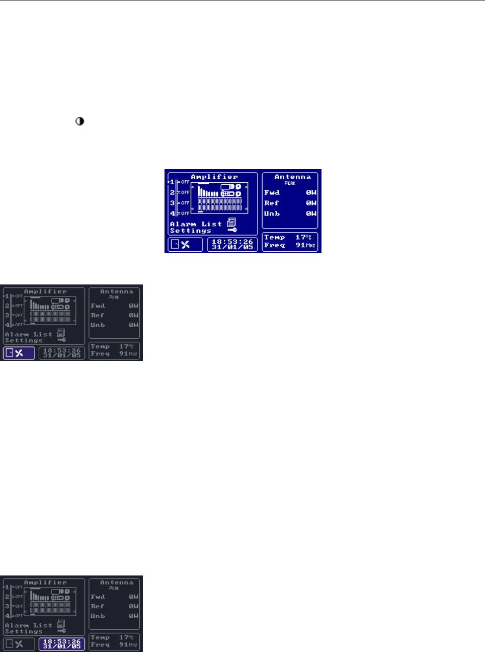
Alarm Window
The alarm window may contain three icons indicating anomalies in the
operation of the transmitter.
The first icon on the left represents the status of the Interlock. If there is no
Interlock alarm, thus the switches chain is closed, the icon is a closed
door. In case of Interlock alarm, it is a blinking open door. In case the
Interlock is disabled, the icon will not be displayed at all.
The second icon, in the middle, refers to the status of the transmitter fans
and can be a still fan (fans aren't rotating) or a moving one (fans are rotating).
It is important to note that this icon represents the status of the FANS
CONTROL contact located on the rear panel, which indicates the actual
work (rotation) of the fans rather than the fact that they are powered or
not. In other words, it is possible that the fans are powered but, for some
anomaly, are not working correctly. In this case the icon is a still fan blinking.
The third icon, on the right, indicates a generic alarm. It is not displayed if
the AC is not detecting any malfunctioning condition, while it is displayed
as a bell in case of any alarm condition. If the alarm condition ends, the bell
blinks to indicate that something happened previously. It stops blinking if
the alarms list (Log) is accessed to check the occurred events.
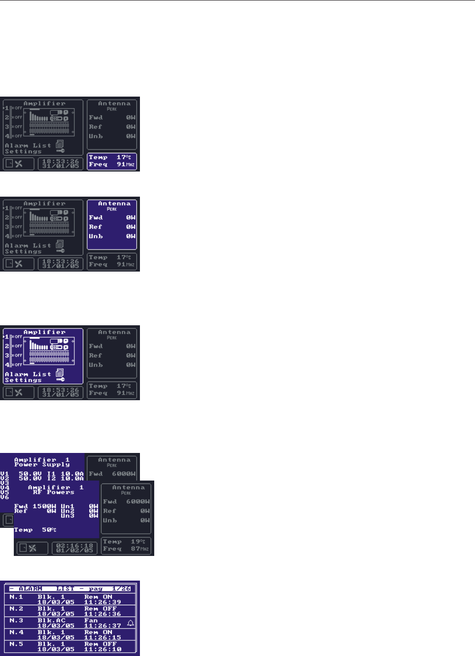
Date and time window
The AC is provided with an internal clock with a backup battery placed
on the display board. The date is used to associate each event in the log to
the exact time at which it occurred. The time can be set from the Settings
menu. The AC synchronizes all of the AMs so that all of them display the
same time.
hard to read, the contrast can be adjusted by acting with a small screwdriver into the hole on the frontal panel
marked with the symbol.
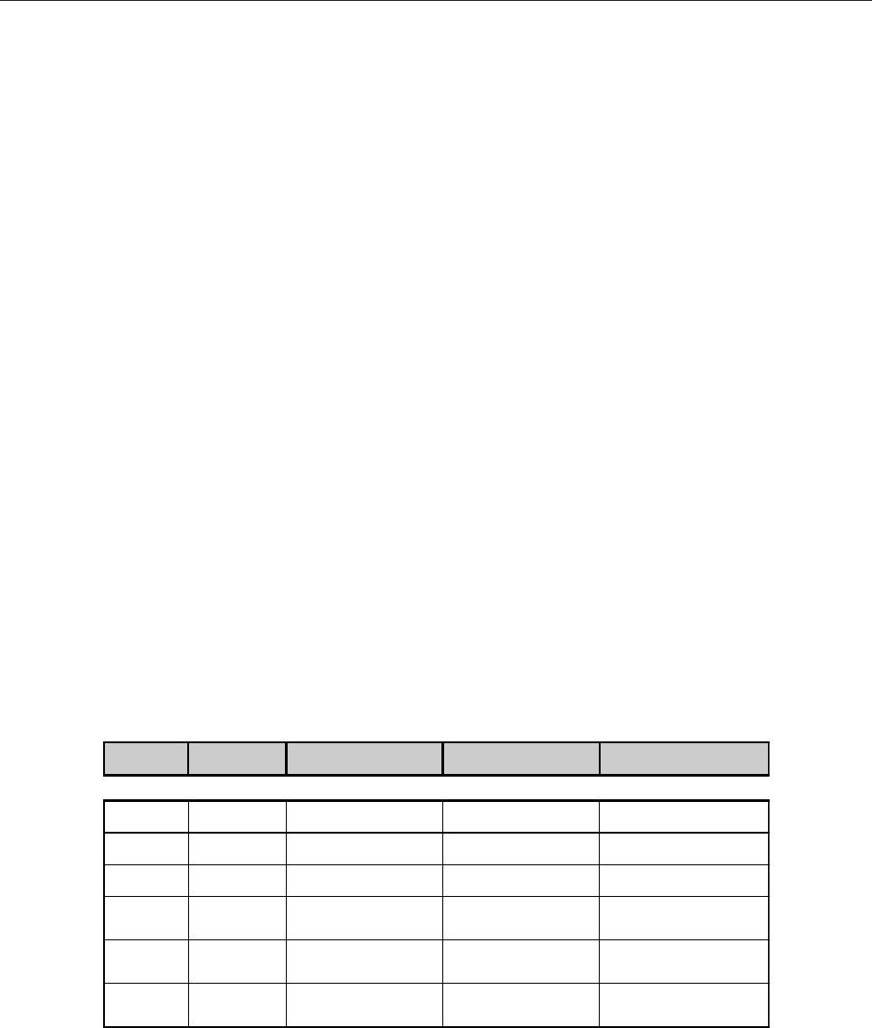
The main screen is similar to the one in figure below. It may change depending on the transmitter, for instance
depending on the number of AMs and unbalancing.
63
Temperature and frequency window
The temperature shown on the display of the AC is the internal temperature
of the device and can be considered as a good estimation of the temperature
inside the rack. The indication of the frequency is only present for some
transmitters, and allows to keep into consideration the different gains of
directional couplers with frequency. It can be set from the Settings menu.
RF powers window
This window shows the measures of the RF powers in antenna and the
unbalancing of the combiners, if any. The number of monitored powers,
especially unbalancing, changes depending on the transmitter. Each power
has an alarm upper threshold, beyond which the relevant indication starts
blinking. This window also shows the kind of measures, which can be
either average quadratic power (RMS, usually used for digital transmitters)
or peak envelopment power (PEP, usually used in analogue transmitters).
Main window
The main window contains the picture and a list of the AMs, numbered in
series starting from 1. Next to each number of the list, the ON/OFF status
of the module is displayed. If any anomaly prevent the correct
communication between the AC and a module, the relevant number would
blink and no status indication would appear.
The arrow buttons allow to move the cursor onto any of the AMs of the
transmitters and on the menu entries Alarm List and Settings.
Pressing the RET button while the cursor is on an AM, all of the monitored
parameters of that module are displayed. Each amplifier has two
associated screens called RF Powers and Power Supply: the first shows
the RF powers and the temperature of the amplifier; the second contains
the parameters of the power supply (voltages and currents). Note that
if the module doesn't communicate correctly with AC, all of the fields
are blank. To go to the next or previous screen press arrow buttons.
Press ESC to return to the main menu.
Alarm list
By pressing the RET button on the Alarm List entry in the main window,
the whole display shows the event list (log) of the transmitter. Each page of
this list contains 5 events sorted in reversed chronological order (the most
recent event is the first in the list), and a maximum of 26 pages are available
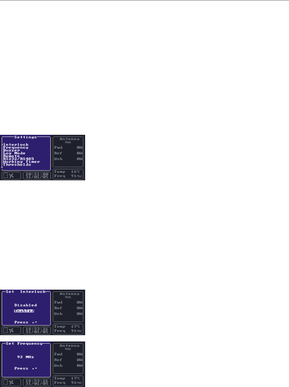
64
(130 events). If the list is full and a new event occurs, the oldest event in
the list is deleted to make free space to the new one.
Each event has an associated number and contains date and time, concerned
module and description of the event. If the event refers to an alarm condition,
a bell icon is displayed on the right. The pages of the list can be scrolled
using the arrow buttons. Press ESC to return to the main window. To
delete all events in the log, press the ESC and RET buttons at the same
time. Make sure to check all events of the log before clearing it.
Settings
The settings window allows to set some of the operating parameters of the
AC. It only covers a portion of the display area, so that the user can keep
the alarm and RF powers window under control.
The Settings menu is composed by a series of parameters which can be
displayed and/or changed. Use the arrow buttons to select a parameter
and press the RET key to open the relevant screen. The display only shows
8 items at any given time: press the DOWN button while the cursor is on
the last displayed item to scroll the menu and show the next one. The UP
button works in the same way if used on the first displayed item of the list.
Press the ESC key to return to the main window. Note that the items
displayed may vary depending on the transmitter and the AC version.
If the selected parameter can be modified, use the arrow buttons to change
its value and the RET one to confirm the change. It is possible to cancel
the change and restore the original value by pressing the ESC button. If
the parameter cannot be modified, it is possible to press ESC to return to
the Settings menu. All the settings of the menu are described below.
Interlock
The AC monitors continuously the status of the Interlock and switches off
the transmitter in case of alarm, until it ends. This function may be disabled
by the Interlock setting menu.
Frequency (only for some transmitters)
In some transmitter the AC keeps into consideration the different coupling
effect of the directional coupler, used to measure the RF powers, compared
to the variation of the frequency. This screen allows to change the frequency
of the antenna signal, setting the frequency of the video carrier in case of
analogue TV transmitters or the middle band frequency in case of digital
or FM transmitters.
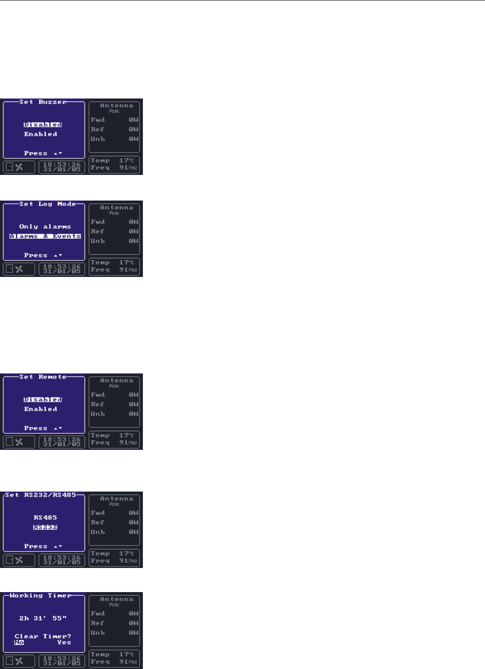
65
Buzzer
The AC uses the buzzer in case of malfunctioning or situations in which the
attention of the user is required. During tests or maintenance it may be
useful to disable the buzzer using this menu.
Generally speaking, it is better to reactivate it during the normal operation
of the transmitter..
Log Mode
The log is a very important feature as it allows the user to know the details
of the alarms and events occurred to the transmitter, even if it is unattended.
It has two modes between which the user may choose. The “Alarms &
Events” mode logs all alarm conditions as well as events such as the local
or remote on/off status changes.
The “Only alarms” mode only logs alarm conditions. It is generally better
to use the Alarms & Events mode, because the log has a higher level of
detail. The “Only alarms” mode should only be used for testing and
maintenance operations, in order to prevent the log to be filled by events
of minor importance.
Remote
Using the RS232 connection on the front panel or the RS485 one on the
rear panel, the AC may be completely controlled from remote, using a
dedicated software. This function may be disabled from the Remote settings
menu. If the remote control is disabled, the parameters of the transmitter
can still be remotely read, but not changed. The REMOTE LED on the
front panel is lit when remote control is enabled, and unlit otherwise.
RS232/RS485
The transmitter can be remotely controlled through the RS232 connection
on the front panel or the RS485 one on the rear panel. It is not possible to
use both connections at the same time, and the desired one must be chosen
from this menu.
Working Timer
The Working Timer counts the seconds in which the transmitter has been
working, i.e. switched on and powered. This screen also allows to reset
the Timer.
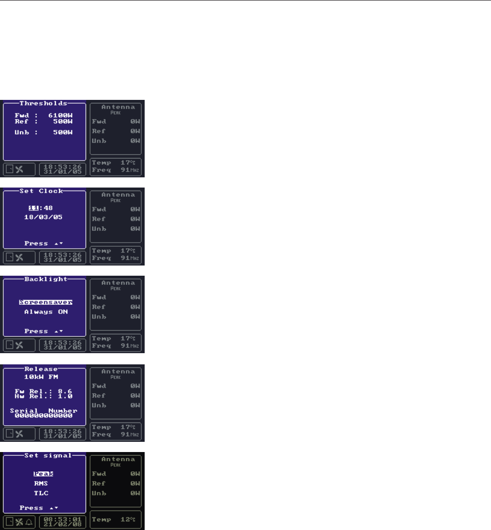
66
Thresholds
Each RF power monitored by the AC should be below a given maximum
threshold. In case a value is beyond the threshold, the AC indicates an
alarm condition. The values of the thresholds are displayed in the Thresholds
menu.
Clock/Date
This menu is used to set the current date and time. Once the changes are
confirmed by pressing the RET button, the AC synchronizes all of the
AMs of the transmitter.
Backlight
The display is provided with a backlight. A Screensaver may be enabled
to make the lamp last longer. When it is, the light is automatically switched
off after 8 minutes without any button being pressed, and it is switched on
again as soon as any button is pressed.
Release
The Release menu shows the kind of the transmitter, the version of the AC
firmware and the serial number of the equipment.
Rms/Peak
The Amplifier Control can detect Peak and RMS RF powers. Tbe Peak
power is used in analog transmitter (FM or TV), the RMS power is used
in digital transmitter.
The user can choose the power detection mode by using the RMS/Peak
menu. In dual-mode (analog and digital) transmitter, the switch between
RMS and Peak power detection can be linked to an ex-ternal input signal
on TELEMEASURES port (see Rear Panel paragraph for more
information). Se-lect TLC item in the RMS/PEak menu to enable this
feature.

67
Section 4 - Diagram
Contents:
- APG012C AMPLIFIER CONTROL Cable Diagram
- APG012C AMPLIFIER CONTROL Component list
- Modules description
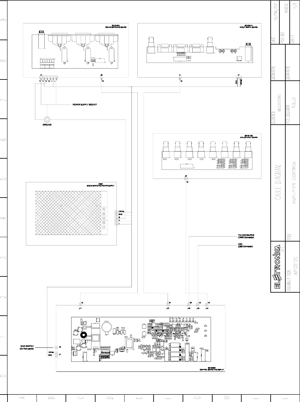
68

69
Elettronika Code Description Qty
02018 BNC CONNECTOR FOR RG174 CABLE 1
02035 BNC CONNECTOR FOR RG316 CABLE 1
02695 DB9 CONNECTOR FOR IU008059 CABLE 1
02699 10 WIRE FEMALE CONNECTOR 3
02700 16 WIRE FEMALE CONNECTOR 4
02740 FEMALE PAN 1
02741 COVER PAN 1
02843 2 POLES SHIELDED SOCKET 2
02855 26 WIRE FEMALE CONNECTOR 1
02856 DB25 FEMALE CONNECTOR 1
02880 10A GREEN SOCKET 1
05504 MECHANICAL DETAIL 1
05525 MECHANICAL DETAIL 2
07524A SWITCH 1
07925 PVC PROTECTION 1
07926 PVC PROTECTION 1
08500 RG174 50Ω CABLE 0.30
C0814 SHIELDED COPPER ADHESIVE 0.50
CON0145 CON0145R1 BOX 1
CON0153 CON0153AR0 MECHANICAL DETAIL 1
DET0313 DET0313R0 3-4U HANDLES 2
E0031 S-60-24 SWITCHING POWER SUPPLY 1
PAN0066 PAN0066AR0 FRONT PANEL 1
SCH0110BR0 ANALOG INPUT BOARD 1
SCH0152AR0 220VAC SWITCHING BOARD 1
SCH0239AR0 CONTROL BOARD AND DISPLAY 1
SCH0241AR0 IN/OUT DIGITAL BOARD 1
V0761 BLACK PLASTIC TAP 6
Component list APG012C

70
This page is intentionally blank

71
CONTROL AND DISPLAY BOARD SCH0239AR0
DESCRIPTION
SCH0239A is the Main Board of the Amplifier Control. It could be considered the core of the equipment.
This board is based on a powerful 16 bit microcontroller that runs an optimized ad-hoc firmware for the transmitter.
The firmware can be simply upgraded by means of RS232 (see the paragraph below for more details).
On the board a small DC/DC power supply is present that converts the +24Vdc input signal to +5Vdc output signal
used for almost all the integrated circuits.
The microcontroller gathers all the informations from AMs (by RS485 bus), antenna directional coupler, interlock
chain, fans and so on. It makes these informations available on the local interface (display and leds) and remote
(RS232, RS485 and TLM).
The analog inputs are conditioned in order to make a good monitoring of the RF powers, RMS and PEP type. The
input gain is variable by a trimmer and should be calibrated as explained below. The internal A/D converter of the
microcontroller makes the sampling and converts these signals into digital.
The LCD has a CCFL backlight that is fed by the inverter INV1 (see the component layout of the board).
All the other boards inside the AC are connected to the display board.
- Dip-switches
On the display board two series of dip-switches are present (see SW1 and SW2 on the component layout).
Switches on SW1 is not used. Switches on SW2 must be set in the following way:
1 Not Used
2 Not Used
3 Not Used
4OFF
5OFF
6ON
7ON
8ON
FIRMWARE UPDATE
The microcontroller is provided with a built-in Flash memory containing the firmware. The firmware can be
updated with a later version without removing the apparatus from the rack and/or replacing the chip.
To upgrade it, connect a PC to the RS232 socket on the front panel of the apparatus by means of a cable
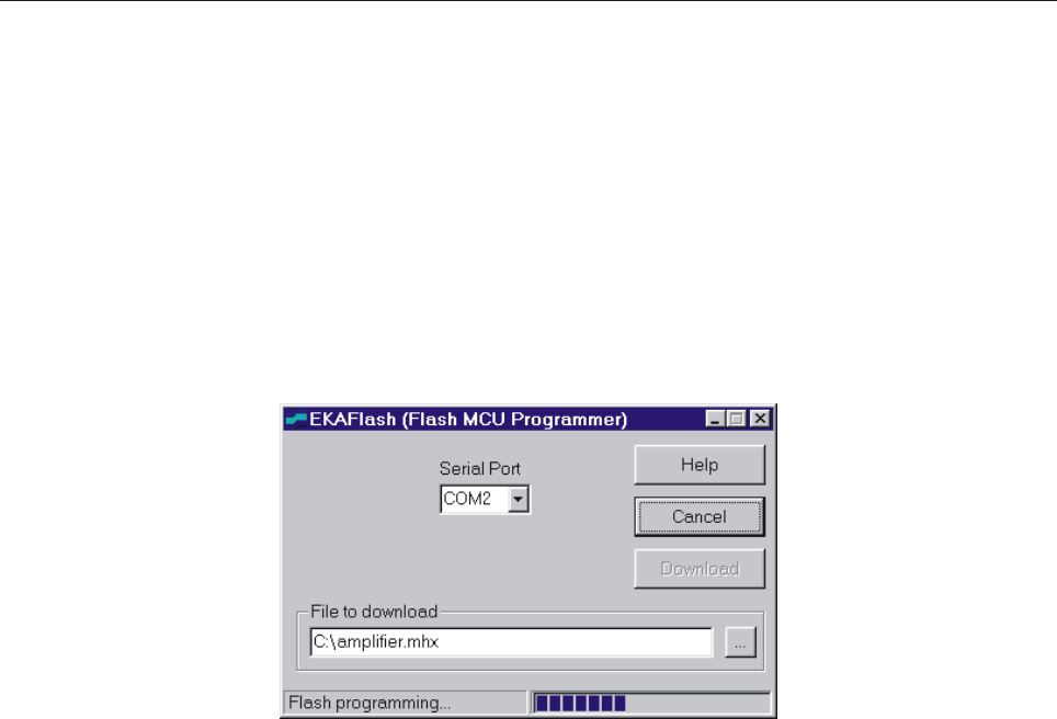
72
DB9 male - DB9 female (pin-to-pin).
Launch on the PC the EKAFlash application, select the serial port in use on the PC, choose the update file by
pressing the “...” key and click on Download button.
Eventually, turn off the AC from the main switch and then turn it on again. The upgrade of the firmware begins
on the EKAFlash window. The figure below shows this window while a firmware is being updated.
The EKAFlash window while updating a firmware
POWER CALIBRATION
FWD Power calibration
Disconnect the antenna and connect a wattmeter to the antenna connector. Give power to the amplifier until
you will read on the wattmeter a value corresponding to the equipment nominal power. Then turn the trimmer
A (see Bottom Component layout), it is a variable resistor used to adjust the A analog input measure until
you read approximately the same FWD power value on the display.
REF Power calibration
Disconnect the antenna and connect a wattmeter to the antenna connector. Connect the Forward power
monitoring cable to the Reflected power input connector. Give power to the amplifier until you will read on the
wattmeter a value corresponding to 10% of the equipment nominal power. Then turn the trimmer B (see
Bottom Component layout), it is a variable resistor used to adjust the B analog input measure until you read
approximately the same REF power value on the display.
UNB Calibration
Connect a wattmeter before the dummy load. Give power to the amplifier then turn off one slave module: you
will read an amount of unbalancing power on the wattmeter. Turn the trimmer C (see Bottom Component
layout), it is a variable resistor used to adjust the C analog input measure until you read approximately the
same UNB power value on the display.
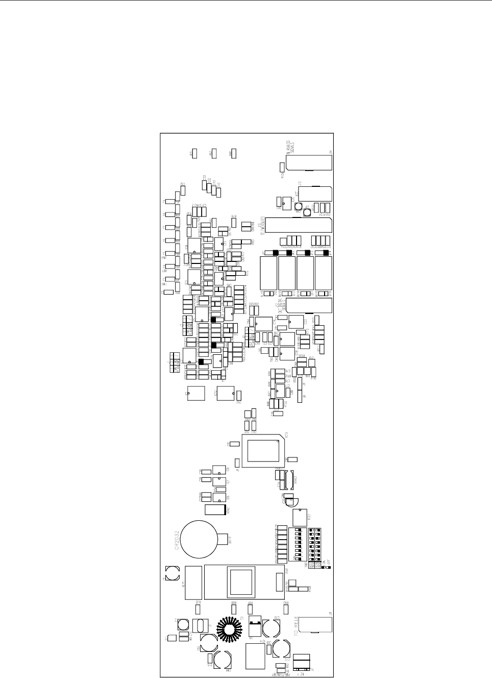
73
SCH0239AR0 Top layer Component layout
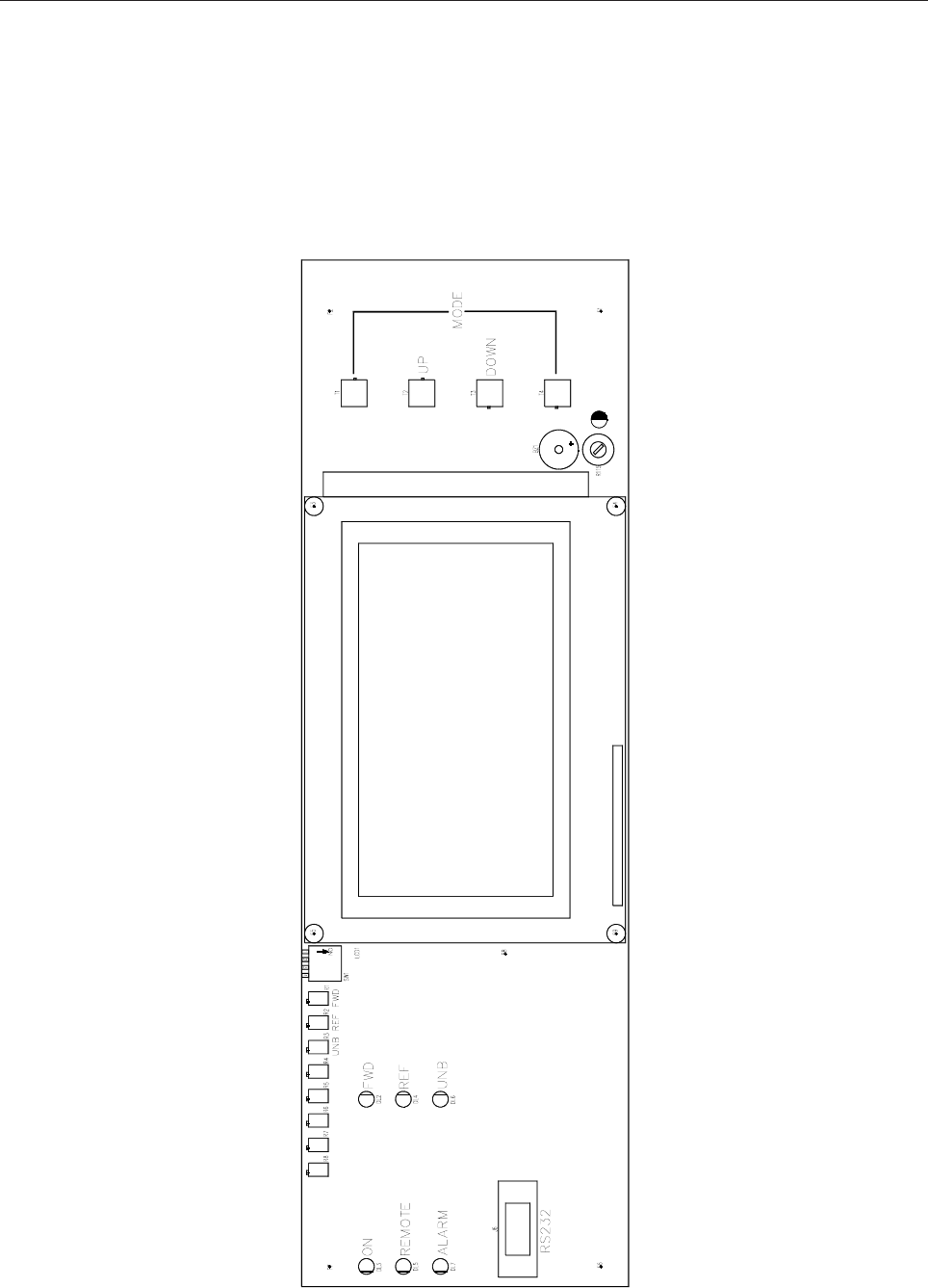
74
SCH0239AR0 Bottom layer Component layout

75
SCH0239AR0 COMPONENT LIST
Part Name/Number Description Qty. Comps. Page 1/2
BATT BH001RB 3093_90 03093 03090 BATTERY HOLDER 1 BATT1
BZ AI-155 03705 03705 5VDC BUZZER 1 BZ1
CC 100nF-S 01065C 01065C Y5V 1206 COND 33 C10, C15, C17-19, C22, C25, C28, C38,
C45, C49-52, C55, C62-63, C68-69, C78,
C80-85, C87-88, C90, C92-95
CC 15pF-S 01088 01088 SMD 1206 COND 2 C74-75
CC 1nF-S 01096 01096 SMD 1206 COND 20 C12-14, C31-33, C42-43, C53-54, C56-58,
C60-61, C66, C76-77, C79, C86
CC 1uF100V-S 01760A 01760A Y5V 1206 COND <<50 V>> 8 C21, C23, C37, C64-65, C67, C71-72
CC 220pF-S 01093 01093 SMD 1206 COND 8 C2-9
CC 47pF-S 01100 01100 SMD 1206 COND 8 C20, C30, C35-36, C40-41, C48, C59
CE 10uF16V-S 01626B TANT. ELETTR SMD CO 8 C24, C26-27, C29, C34, C39, C46-47
CE 1uF50V-S 01763A 01763A ELETTR SMD COND 2 C89, C91
CE 220uF50V LOW ESR 1799A ELETTR SMD COND LOW ESR 4 C16, C44, C70, C73
CE 47uF35V-S 01790A 01790A ELETTR SMD COND 1 C11
CE 47uF50V-S 01791C 01791C ELETTR SMD COND 1 C1
D 1N4148-S 03002 03002 SMD DIODE 4 D12-13, D17, D19
D 50WQ06FN 03019A SMD DIODE SCHOTTKY 5,5A 1 D9
D BAS85-S 03024 SMD DIODE SCHOTTKY 8 D1-8
D BAT54S 03199 SMD SCHOTTKY DIODE A-K T 6 D10-11, D14-16, D18
DIS WG240128B 03083 240/128 DOT MATRIX LCD 1 LCD1
DL KA-3528SGC 03057 03057 GREEN SMD LED DIODE 1 DL1
DL LEDG3 03053 03053 GREEN LED DIODE 3mm 1 DL3
DL LEDR3 03058 03058 RED LED DIODE 3mm 4 DL2, DL4, DL6-7
DL LEDY3 03051 03051 YELLOW LED DIODE 3mm 1 DL5
IC 24LC64 04815 04815 SMD INTEG CIRCUIT 1 IC7
IC 74HC00-S 4762A 4762A SMD INTEG CIRCUIT 1 IC19
IC 82B715-S 04734A 04734A SMD INTEG CIRCUIT 1 IC17
IC CD4053BC-S 04710A 04710A SMD INTEG CIRCUIT 1 IC12
IC LM2596S-5.0 04580 SMD INTEG CIRCUIT 1 IC14
IC LM75-S 00668 00668 SMD INTEG CIRCUIT 1 IC8
IC LMC6482-S 04632 SMD INTEG CIRCUIT 1 IC20
IC LMC6484-S 04634 SMD INTEG CIRCUIT 4 IC2-5
IC M41T56 04611 04611 SMD INTEG CIRCUIT 1 IC6
IC MAX232-S 04804B 04804B SMD INTEG CIRCUIT 1 IC16
IC MAX3080-S 04770 04770 SMD INTEG CIRCUIT 1 IC22
IC MAX3080-S N.M. NOT MOUTED SMD INTEG CIRCUIT 1 IC18
IC MAX942CSA-S 04572 SMD INTEG CIRCUIT 4 IC9-11, IC13
IC MB90F543PF 04596 SMD INTEG CIRCUIT 1 IC15
IC MPC100T-450I-TT 04577 SMD INTEG CIRCUIT 1 IC21
IC ULN2003A 4870 04870 SMD INTEG CIRCUIT 2 IC1, IC23
IND MS85 10uH-S 04948 INDUCTOR 2,7A 1 L1
IND T100uH-1.8A 4958 04958 TOROIDAL-STORAGE CHOKES 1 L2

76
Part Name/Number Description Qty. Comps. Page 2/2
INV IN-D43A-5V 03085 DC/AC MODULE 1 INV1
J DB9_F-0° LT 02794 PCB CONNECTOR DB9 LONG T 1 J6
J FC-10P 02697-02699 02697+02699 PCB CONNECTOR POL 2 J11, J13
J FC-16P 02701-02700 02701+02700 PCB CONNECTOR POL 2 J12, J14
J FC-26P 02855-02854 02855+02854 PCB CONNECTOR POL 1 J10
J PAN2 02739 02739 PCB CONNECTOR 1 J4
J PAN2 02739-40-41 02739+02740+02741 PCB CONNECTO 1 J5
J PAN3 02707 02707 PCB CONNECTOR 3 J1-3
J PAN3 NOT MOUNTED NOT MOUNTED PCB CONNECTOR 2 J8-9
J SCREWCONN2 02853 02853 PCB SCREW CONNECTOR 1 J7
JU JUMP3 02707-02742 02707+02742 MASCHIO PAN3 4 JP1-4
R 100R-S 00029A 00029A RES 1/4W 5% SMD 1206 6 R109, R114, R119-121, R123
R 10K-S 00053A 00053A RES 1/4W 5% SMD 1206 37 R22-27, R30, R32-33, R40, R47, R50, R57,
R68, R81-82, R85, R90-101, R105-108,
R116, R118, R122, R124
R 120R-S 00030A 00030A RES 1/4W 5% SMD 1206 2 R112-113
R 1K0-S 00041A 00041A RES 1/4W 5% SMD 1206 5 R46, R54, R87-88, R104
R 1K5-S 00043A 00043A RES 1/4W 5% SMD 1206 2 R110-111
R 22K-S 00057A 00057A RES 1/4W 5% SMD 1206 11 R18, R20-21, R28, R34, R36, R38-39, R41,
R43-44
R 2K2-S 00045A 00045A RES 1/4W 5% SMD 1206 8 R19, R35, R37, R42, R45, R53, R59-60
R 330R-S 00035B 00035B RES 1/4W 5% SMD 1206 2 R89, R103
R 33R-S 00023A 00023A RES 1/4W 5% SMD 1206 2 R86, R102
R 470K-S 00073A 00073A RES 1/4W 5% SMD 1206 8 R48-49, R51-52, R55-56, R58, R65
R 470R-S 00037A 00037A RES 1/4W 5% SMD 1206 30 R10-17, R29, R31, R61-64, R66-67,
R69-80, R83-84
R 4K7-S 00049A 00049A RES 1/4W 5% SMD 1206 1 R117
R 820R-S 00040A 00040A RES 1/4W 5% SMD 1206 1 R9
RL 30.22.24 07569 07569 RELE 5 RLY1-5
RV 10K-S-H 00715 00715 VARIABLE RESISTOR 1 R115
RV 1M-3266X 00815 VARIABLE RESISTOR 8 R1-8
SW SWITCH-4DIP 90° 07531A PCB DIP SWITCH 90° 1 SW1
SW SWITCH-8DIP 07530A PCB DIP SWITCH SMD 1 SW2
T 06086 N 7630 7632 7630 7632 KTI06086 PULSANTE 2 4 T1-4
TR BC848 03457 03457 NPN SMD TRANSISTOR 1 TR1
XTAL 32.768k-S 05146 05146 QUARTZ 1 XTAL1
XTAL 4MHz-S 05101A 05101A QUARTZ 1 XTAL2
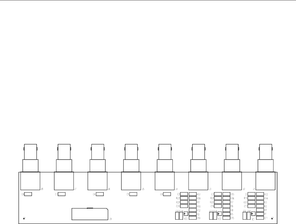
77
ANALOG INPUT BOARD SCH0110BR0
SCH0110BR0 COMPONENT LIST
Part Name/Number Description Qty. Comps.
CC 1206 N. M. N. M. SMD 1206 CAPACITOR 17 C4-20
CC 1nF-S 01096 01096 SMD 1206 CAPACITOR 3 C1-3
J BNC-90G-PCB 2034 02034 PCB CONNECTOR 3 J1-3
J BNC-90G-PCB 2034 N. M. BNC-90G 5 J4-8
J FC-16P 02701-02700 02701+02700 PCB CONNECTOR POL 1 J9
R 0R0-S 00001 00001 RES 1/4W 5% SMD 1206 6 R13, R15, R17, R19, R21, R23
R 1206 N. M. N. M. RES 1/4W 5% SMD 1206 18 R1-12, R14, R16, R18, R20, R22
R24
Z MICRO SOIC 8P N.M. SMD INTEG CIRCUIT NOT MOUNTED 3 IC1-3
DESCRIPTION
SCH0110B is a simple board with 8 BNC connectors (only some of them can be mounted depending on the
transmitter). It routes all the 8 analog input signals (usually for power monitoring) on a IDC connector for
simple wiring with the display board.
SCH0110BR0 Component layout
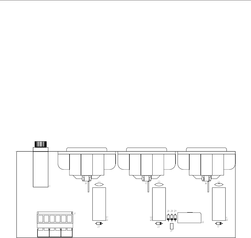
78
220VAC SWITCHING BOARD SCH0152AR0
SCH0152AR0 COMPONENT LIST
Part Name/Number Description Qty. Comps.
CC 2nF2 2kV 01045A 01045A CERAMIC CAPACITOR 3 C1-3
D 1N4148 03001 03001 DIODE 6 D1-6
FUSE OMEGA C1034 FUS00008 FUSE-HOLDER 5x20 D 1 F1
J CON HD515V/05-6PVE 02883 + 02884 PANDUIT PCB CONN 1 J1
J FC-10P 02697-02699 02697+02699 PCB CONNECTOR POL 1 J9
J VASCHETTA IEC 02879 VASCHETTA FEMALE PCB 3 J6-8
JU JUMP2 02739-02742 02739+02742 MALE PAN2 1 JP1
RL 40.31.24 7567C RELE 3 RLY1-3
DESCRIPTION
The SCH0152A board is based on three relays, each for one power connector (DRIVER1 POWER,
DRIVER2 POWER, FANS POWER). The board is directly connected to the mains power supply and
controlled by the SCH0239A (Control Board). When the microcontroller on SCH0239A decides to switch-
on the DRIVER1, for example, it activates the regarding relay on SCH0152A, connecting the main power
supply with the DRIVER1 POWER.
SCH0152AR0 Component layout
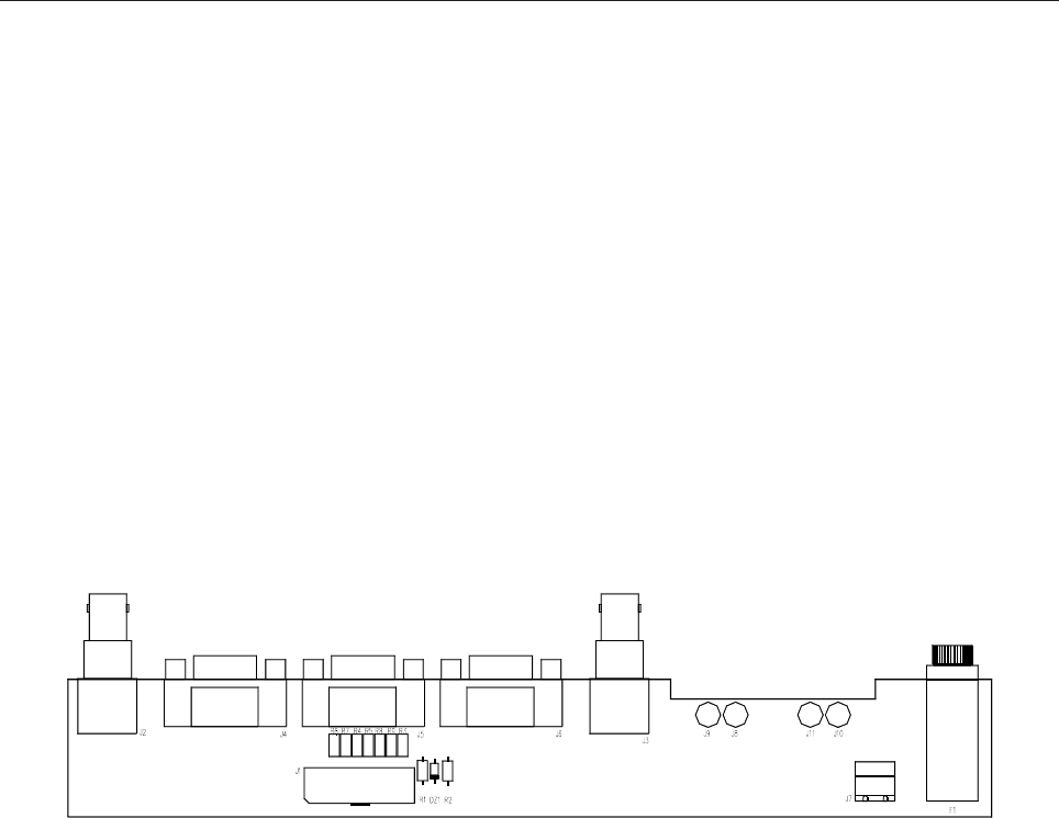
79
IN/OUT DIGITAL BOARD SCH0241AR0
SCH0241AR0 COMPONENT LIST
Part Name/Number Description Qty. Comps.
DZ 5V1 03109 03109 ZENER DIODE 1 DZ1
FUSE OMEGA C1034 FUS00008 PORTA FUSIBILE 5x20 D 1 F1
J BNC-90G-PCB 2034 02034 PCB CONNECTOR 2 J2-3
J DB9-90G 02797 02797 PCB CONNECTOR 3 J4-6
J FC-16P 02701-02700 02701+02700 PCB CONNECTOR POL 1 J1
J SCREWCONN2 02853 02853 PCB SCREW CONNECTOR 1 J7
J TESTP2.5mm 07912 07912 TEST POINT 4 J8-11
R 0R0-S 00001 00001 RES 1/4W 5% SMD 1206 7 R3-9
R 10K 0053 0053 RES 1/4W 5% 1 R1
R 1K0 0041 0041 RES 1/4W 5% 1 R2
DESCRIPTION
Several connectors are present on SCH0241A: 2 D-SUB9F for the RS485 AMs bus, 1 D-SUB9F for
RS485 dedicated to the remote control, 2 BNC for Interlock and Fans control, 2 dual-poles connectors for
+24Vdc power supply output, 1 fuse-holder that accepts the fuse for +24Vdc power signal.
As the other boards, SCH0241A is connected with display board. Also, it is directly connected to the output
of the internal AC/DC power supply (+24Vdc).
SCH0241AR0 Component layout
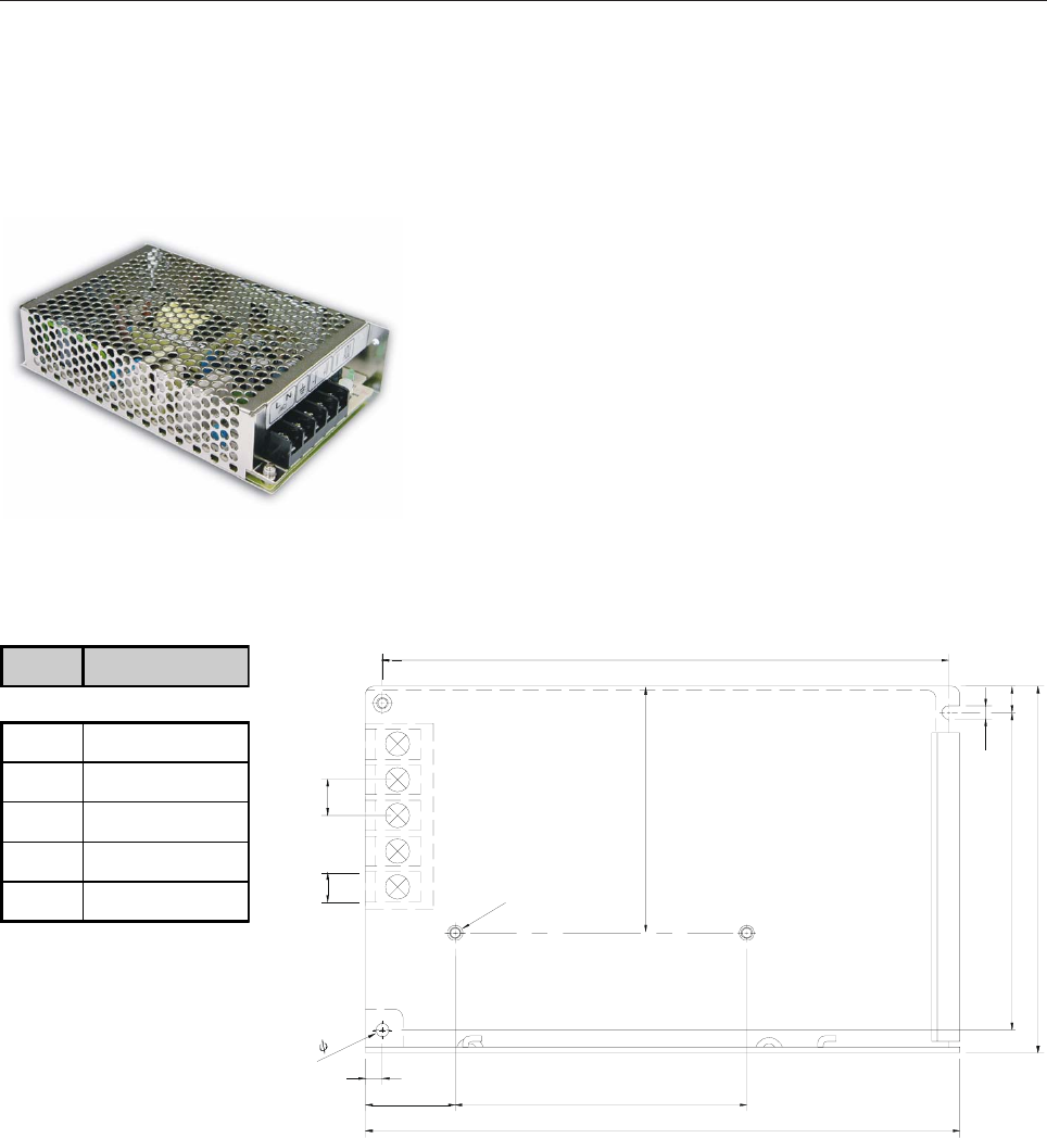
80
S-60-24 SWITCHING POWER SUPPLY E0031
MAIN FEATURES
- Universal AC input / Full range
- Protections: Short circuit / Over load / Over voltage
- Cooling by free air convection
- 100% full load burn-in test
- Fixed switching frequency at 50kHz
MECHANICAL SPECIFICATION
4.5
65
152.5
97
84.5 7
2-M3
78
24
159
3.5
3.5
5
4
3
2
8.2 9.5
1
PIN N° ASSIGNMENT
1AC/L
2AC/N
3FG
4 DC OUTPUT -V
5DC OUTPUT +V
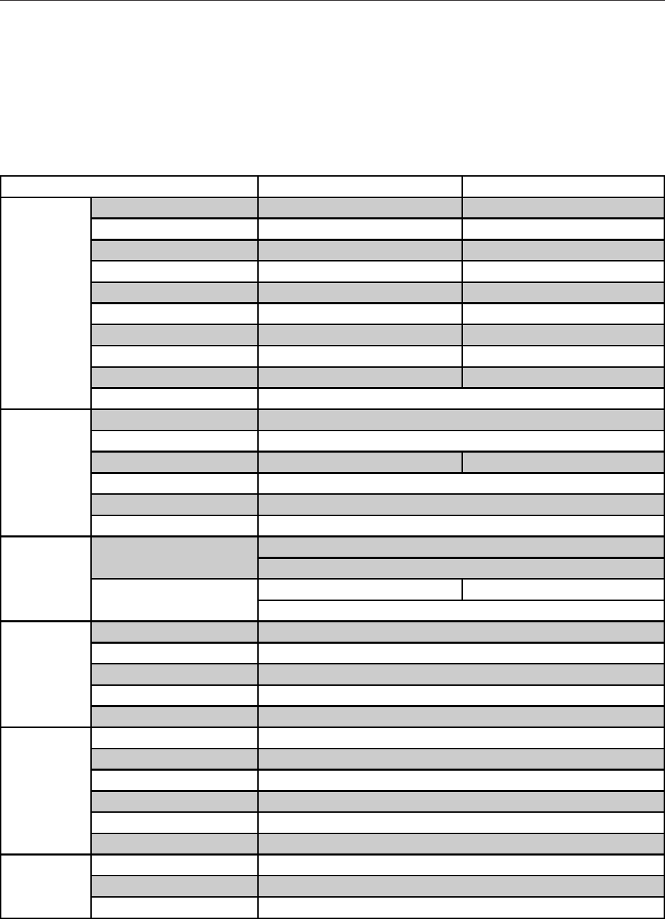
81
TECHNICAL CHARACTERISTICS
MODEL S-60-15 S-60-24
OUTPUT
DC VOLTAGE 15V 24V
RATED CURRENT 4A 2.5A
CURRENT RANGE 0 ~ 4A 0 ~ 2.5A
RATED POWER 60W 60W
RIPPLE & NOISE (max.) Note 2 150mVp-p 150mVp-p
VOLTAGE ADJ. RANGE 13.5 ~ 16.5V 21.6 ~ 26.4V
VOLTAGE TOLERANCE Note 3 ± 1.0% ± 1.0%
LINE REGULATION ± 0.5% ± 0.5%
LOAD REGULATION ± 0.5% ± 0.5%
SETUP, RISE, HOLD TIME 300ms, 50ms, 80ms / 230VAC 800ms, 50ms, 10ms / 115VAC at full load
INPUT
VOLTAGE RANGE 88 ~ 264VAC 120 ~ 370VDC
FREQUENCY RANGE 47 ~ 63Hz
EFFICIENCY (Typ.) 77% 79%
AC CURRENT 24A/115VAC 1A/230VAC
INRUSH CURRENT (Max.) COLD START 30A/115VAC 60A/230VAC
LEAKAGE CURRENT <3.5mA/240VAC
PROTECTION
OVER LOAD 105 ~ 150% rated output power
Protection type: Hiccup mode, recovers automatically after fault condition is removed
OVER VOLTAGE 17.25 ~ 20.25V 27.6 ~ 32.4V
Protection type: Hiccup mode, recovers automatically after fault condition is removed
ENVIRONMENT
WORKING TEMP. -10 ~ +60°C (Refer to output load derating curve)
WORKING HUMIDITY 20 ~ 90% RH non-condensing
STORAGE TEMP., HUMIDITY -20 ~ +85°C, 10 ~ 95% RH
TEMP. COEFFICIENT ± 0.03%/°C (0 ~ 50°C)
VIBRATION 10 ~ 500Hz, 2G 10min./1cycle, period for 60min. each along X, Y, Z axes
SAFETY & EMC
(Note 4)
SAFETY STANDARDS UL1012, UL1950, TUV EN60950 Approved
WITHSTAND VOLTAGE I/P-O/P:3KVAC I/P-FG:1.5KVAC O/P-FG:0.5KVAC
ISOLATION RESISTANCE I/P-O/P, I/P-FG, O/P-GD:100M Ohms/500VDC
EMI CONDUCTION & RADIATION Compliance to EN55022 (CISPR22) Class B
HARMONIC CURRENT Compliance to EN61000-3-2,-3
EMS IMMUNITY Compliance to EN61000-4-2,3,4,5,6,8,11; ENV50204, EN55024, Light industry level, criteria A
OTHERS
MTBF 316.2K hrs min. MIL-HDBK-217F (25°C)
DIMENSION 159*97*38mm (L*W*H)
PACKING 0.51kg; 24pcs/13.1kg/0.7CUFT
82