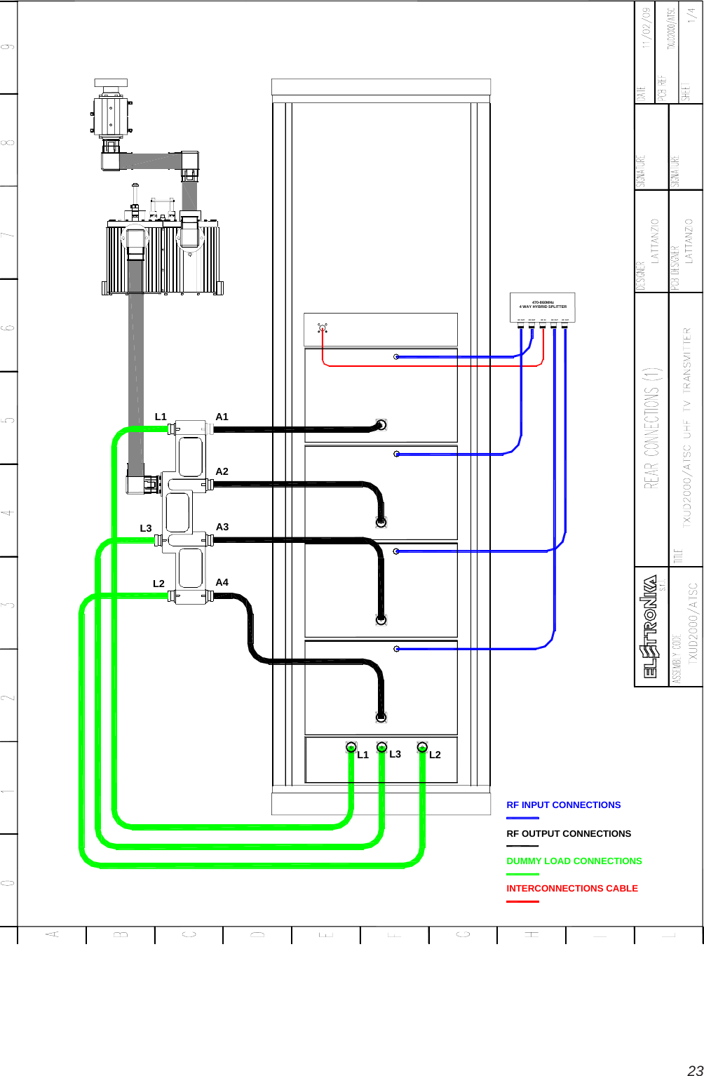
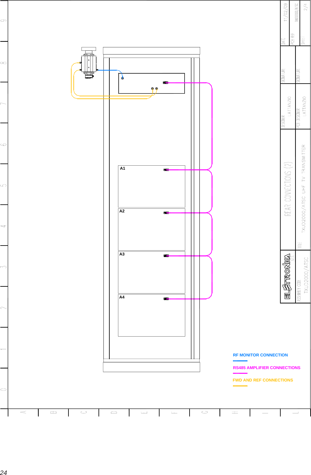
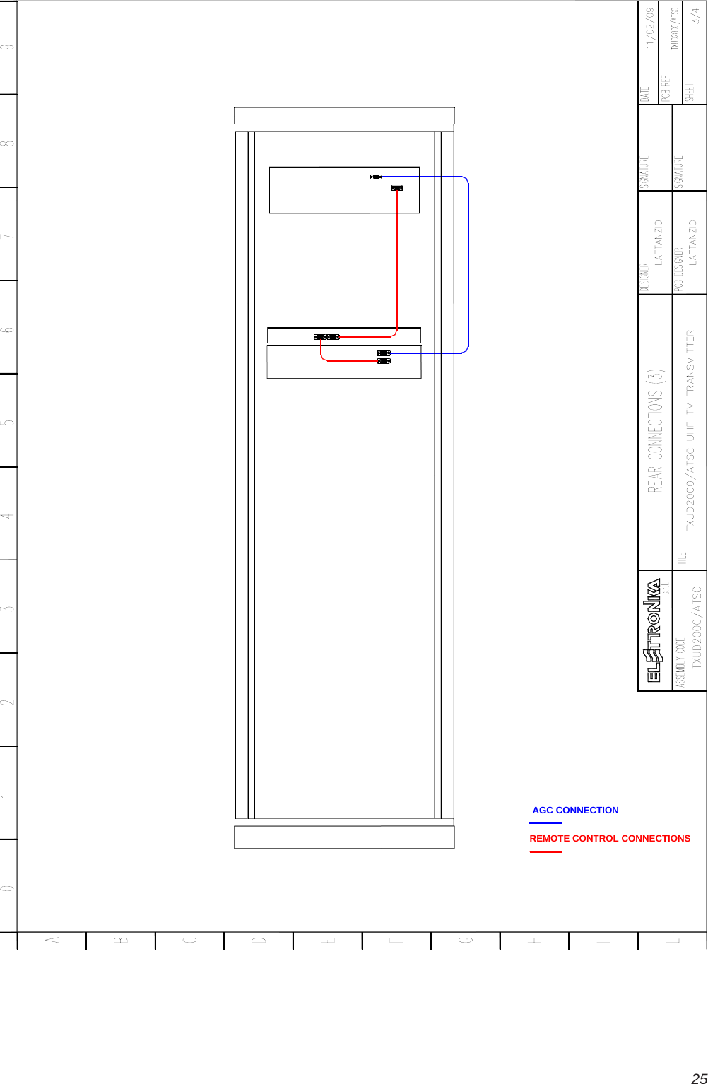
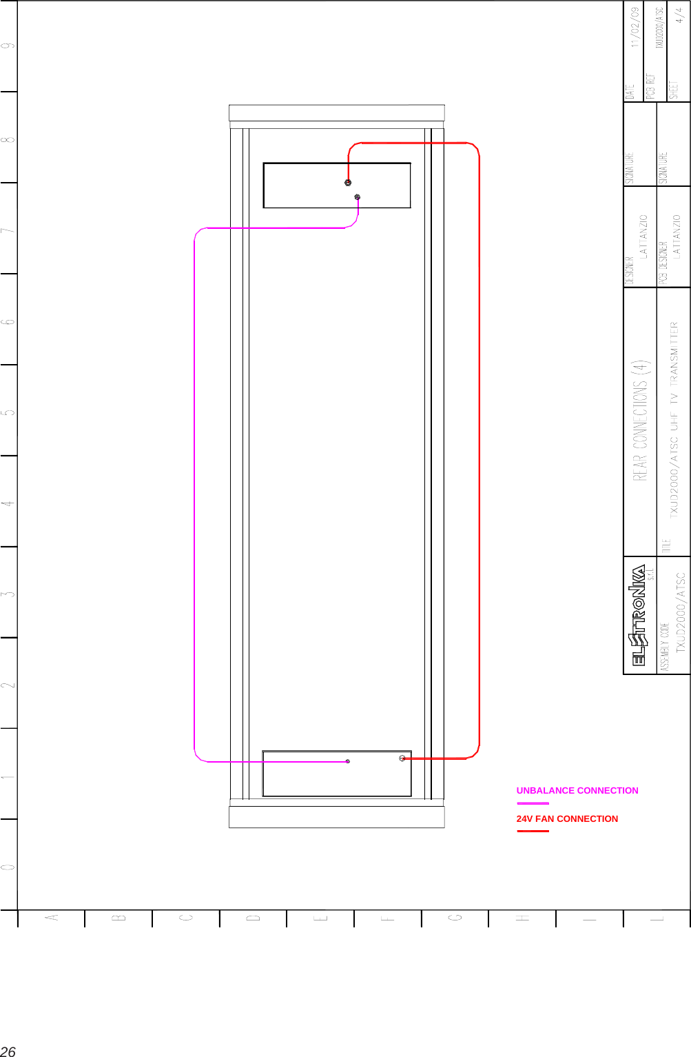
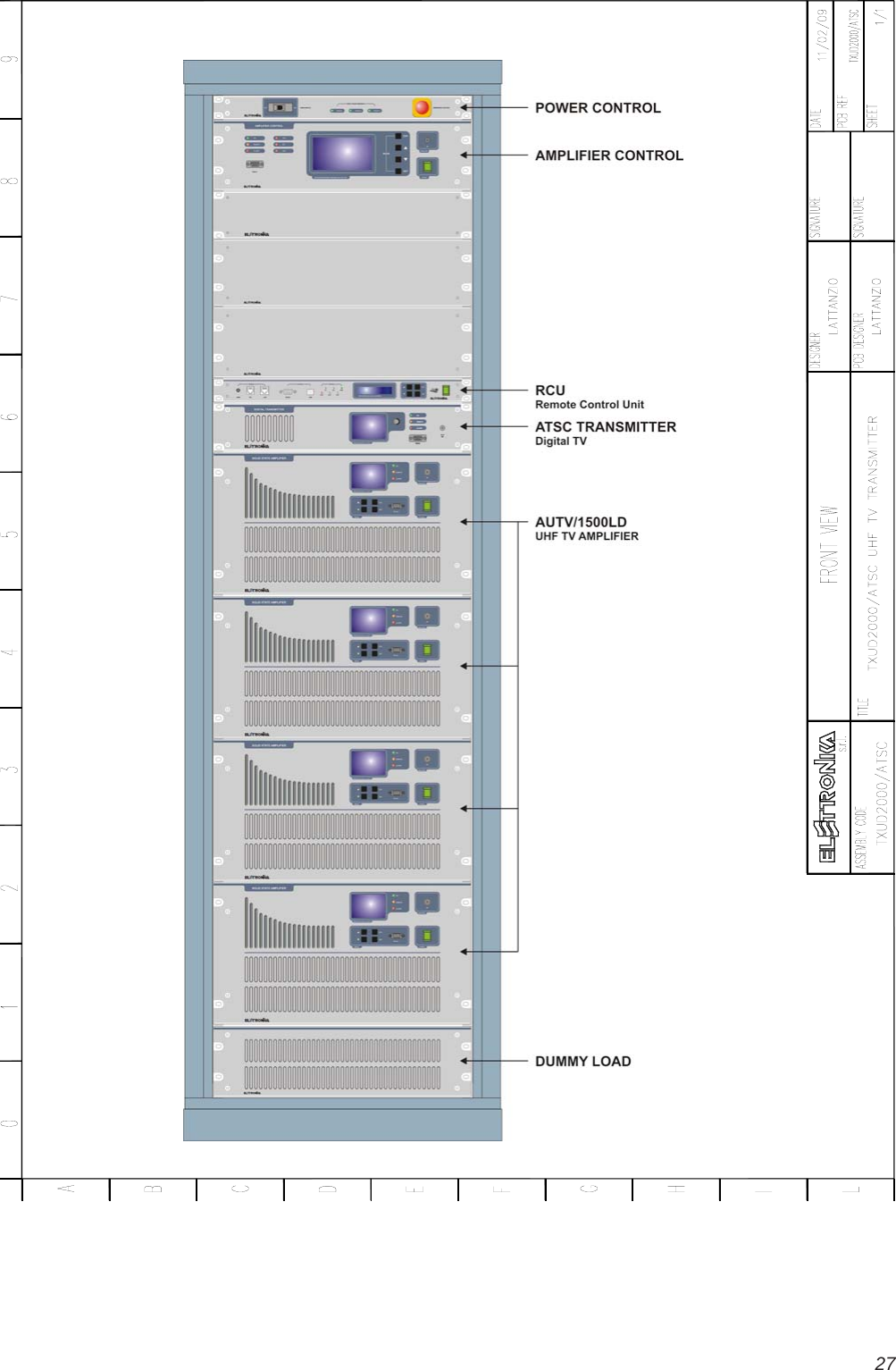
Elettronika S r l TXUD2000A 2000 Watt ATSC Transmitter User Manual TXUD2000 ATSC UHF TV TRANSMITTER PMD

Elettronika S.r.l. 2000 Watt ATSC Transmitter TXUD2000 ATSC UHF TV TRANSMITTER PMD

Contents

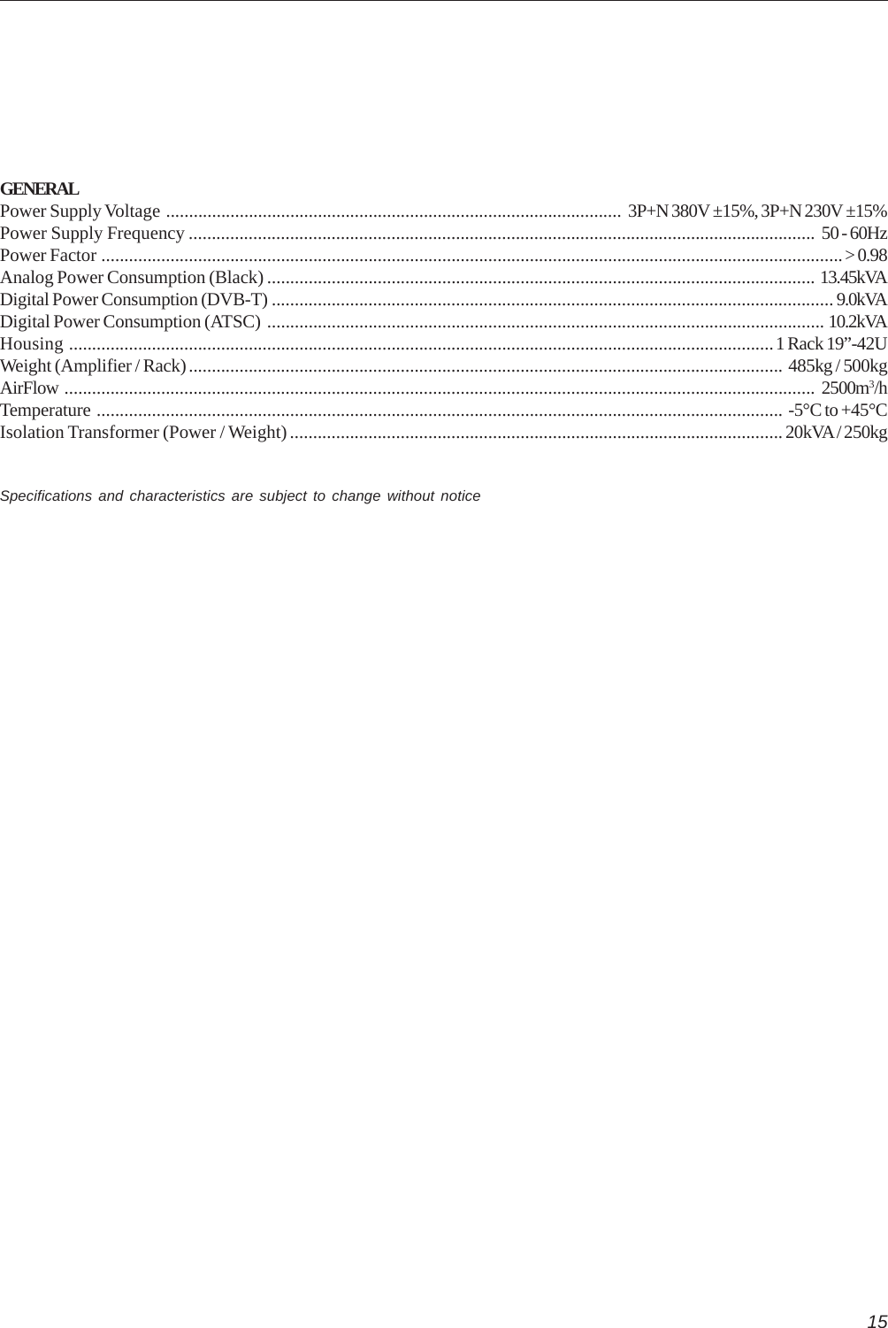
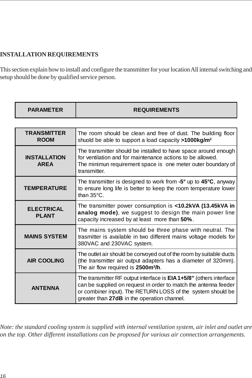
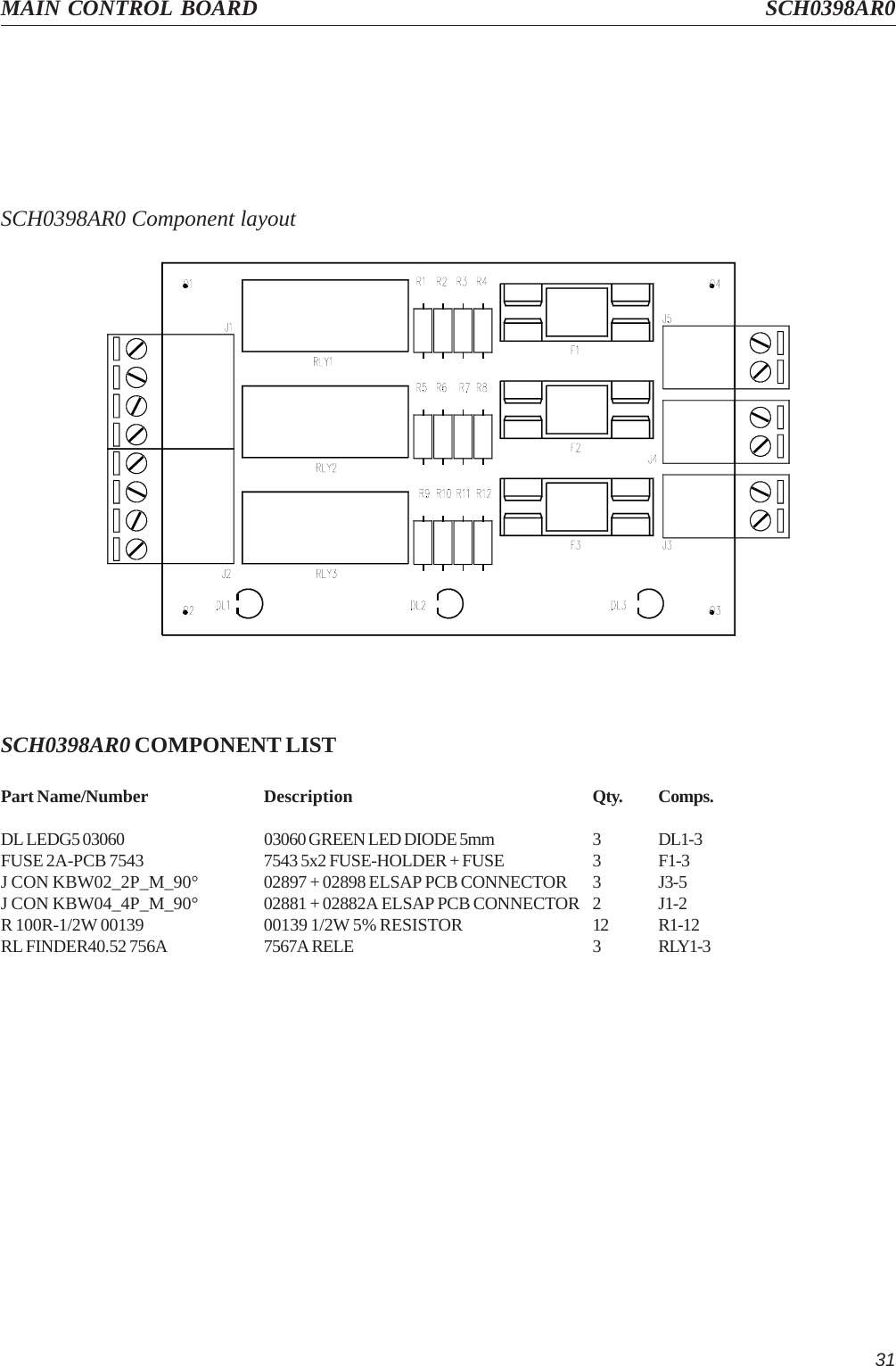
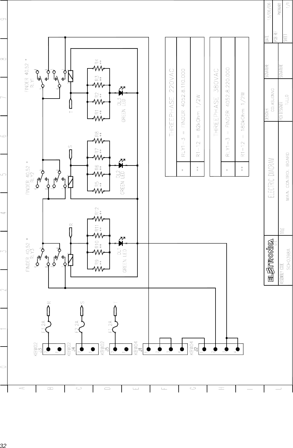
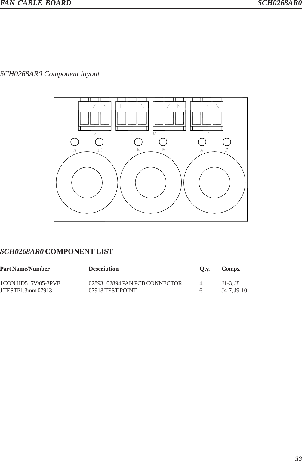
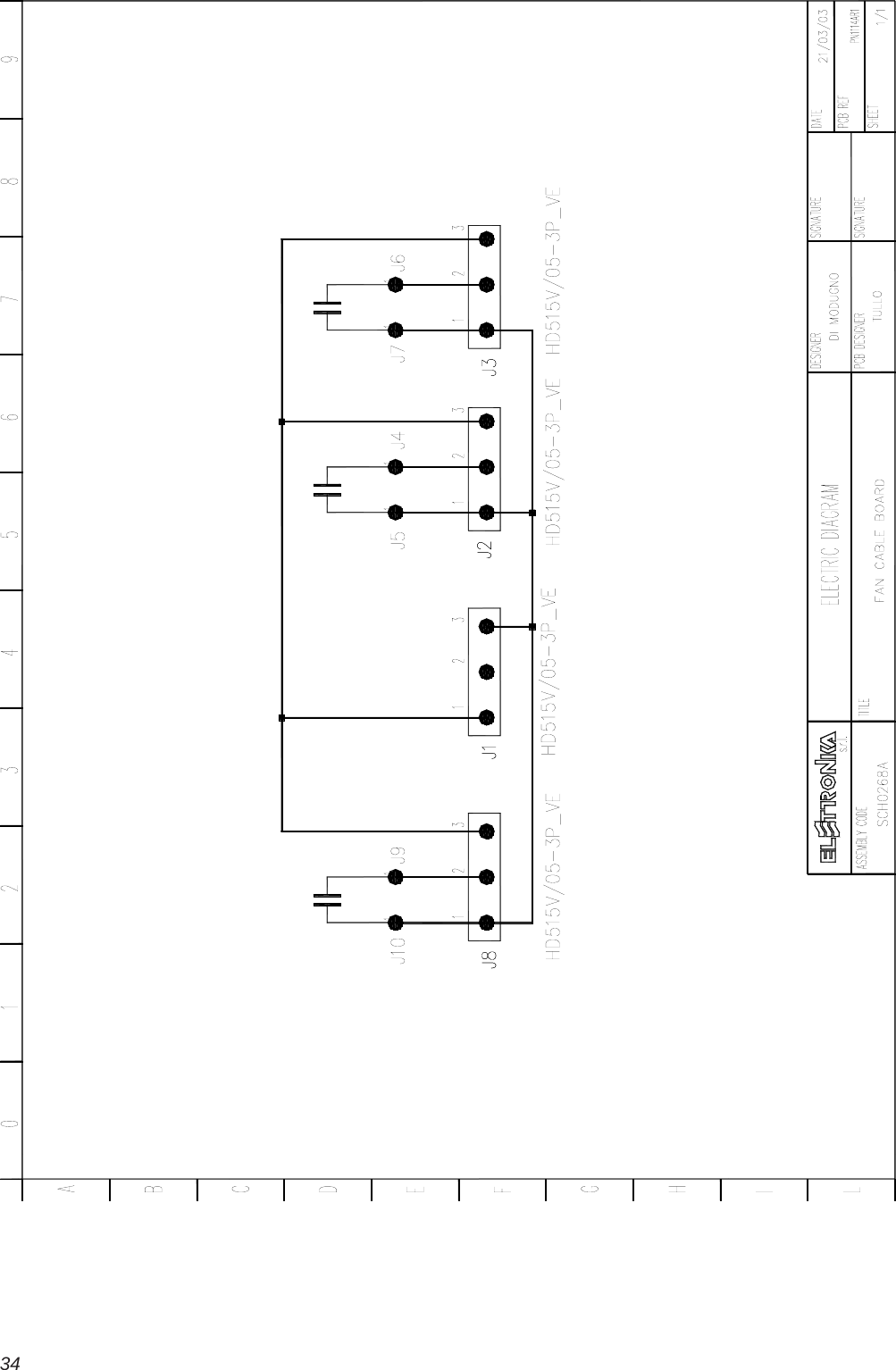
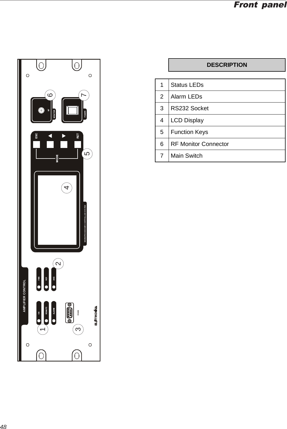
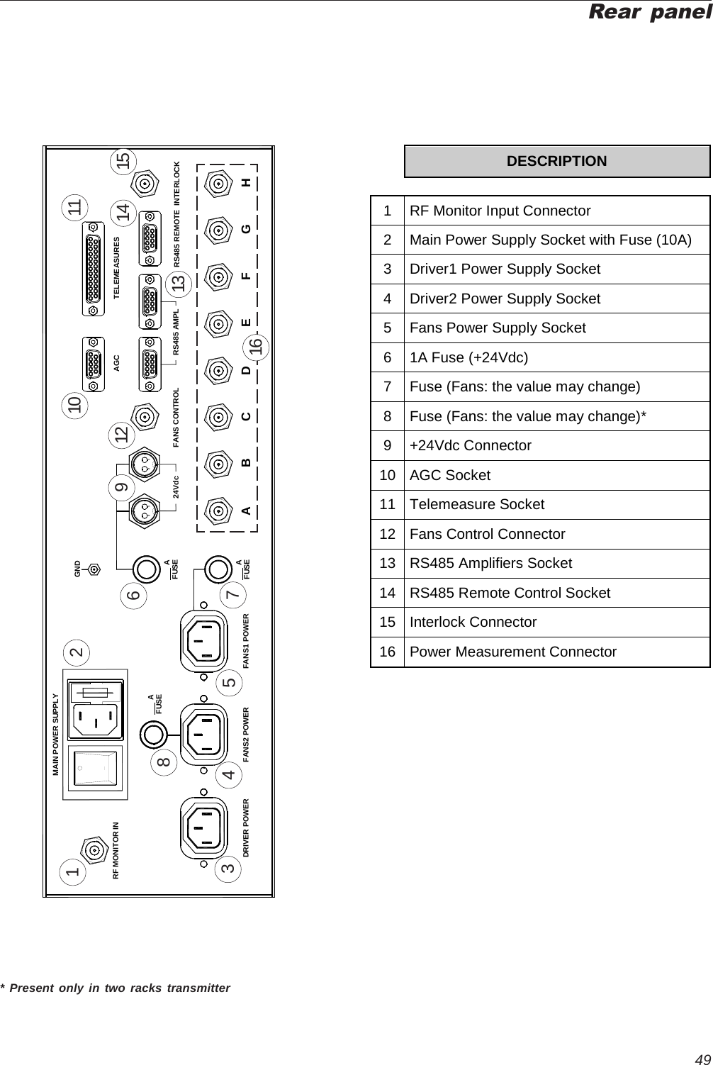
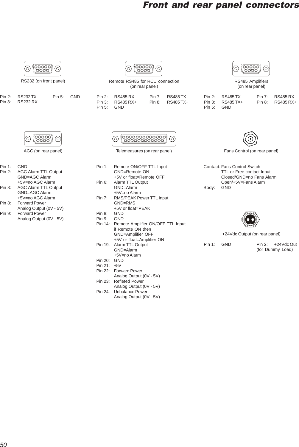
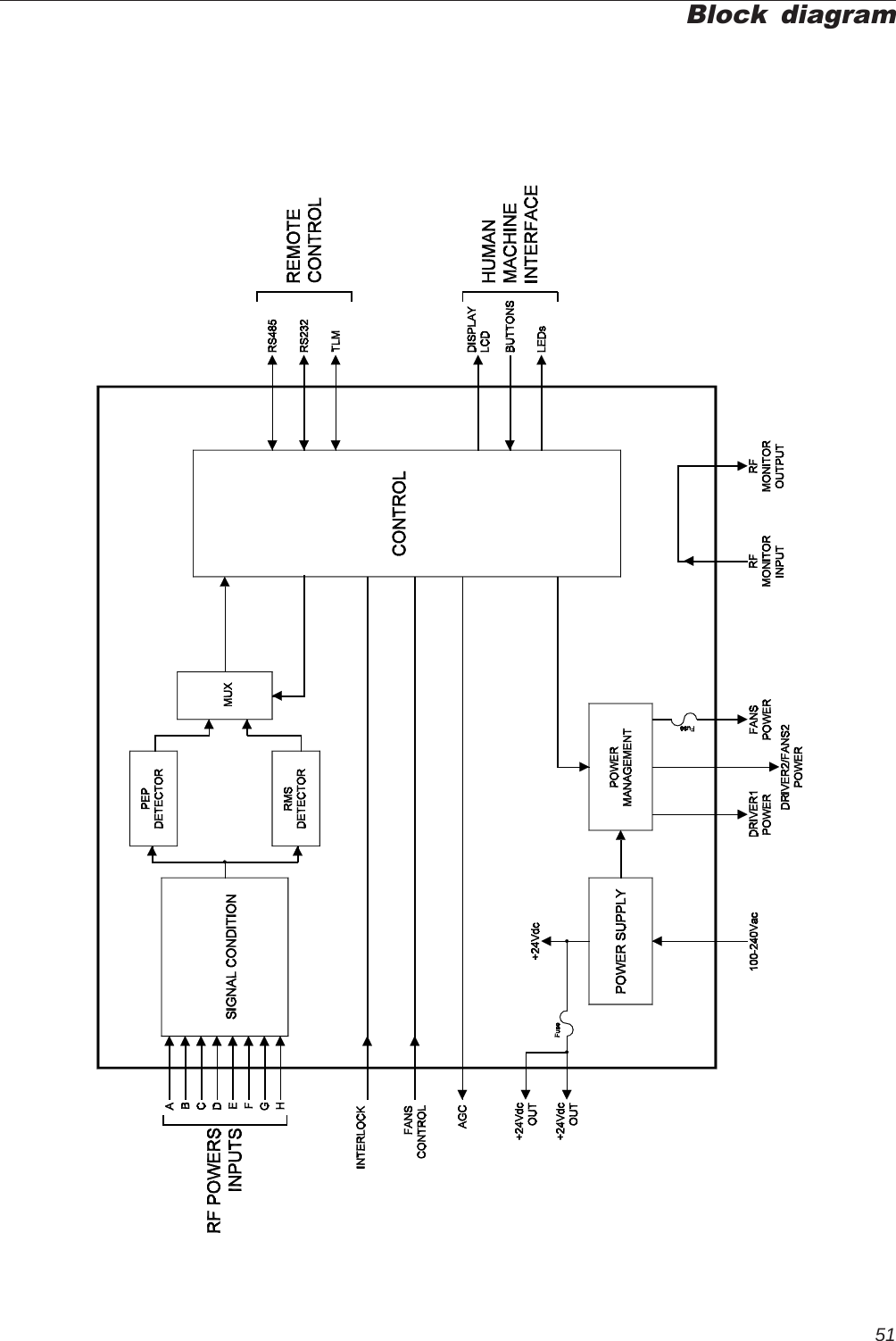
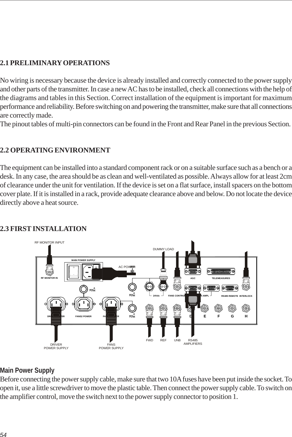
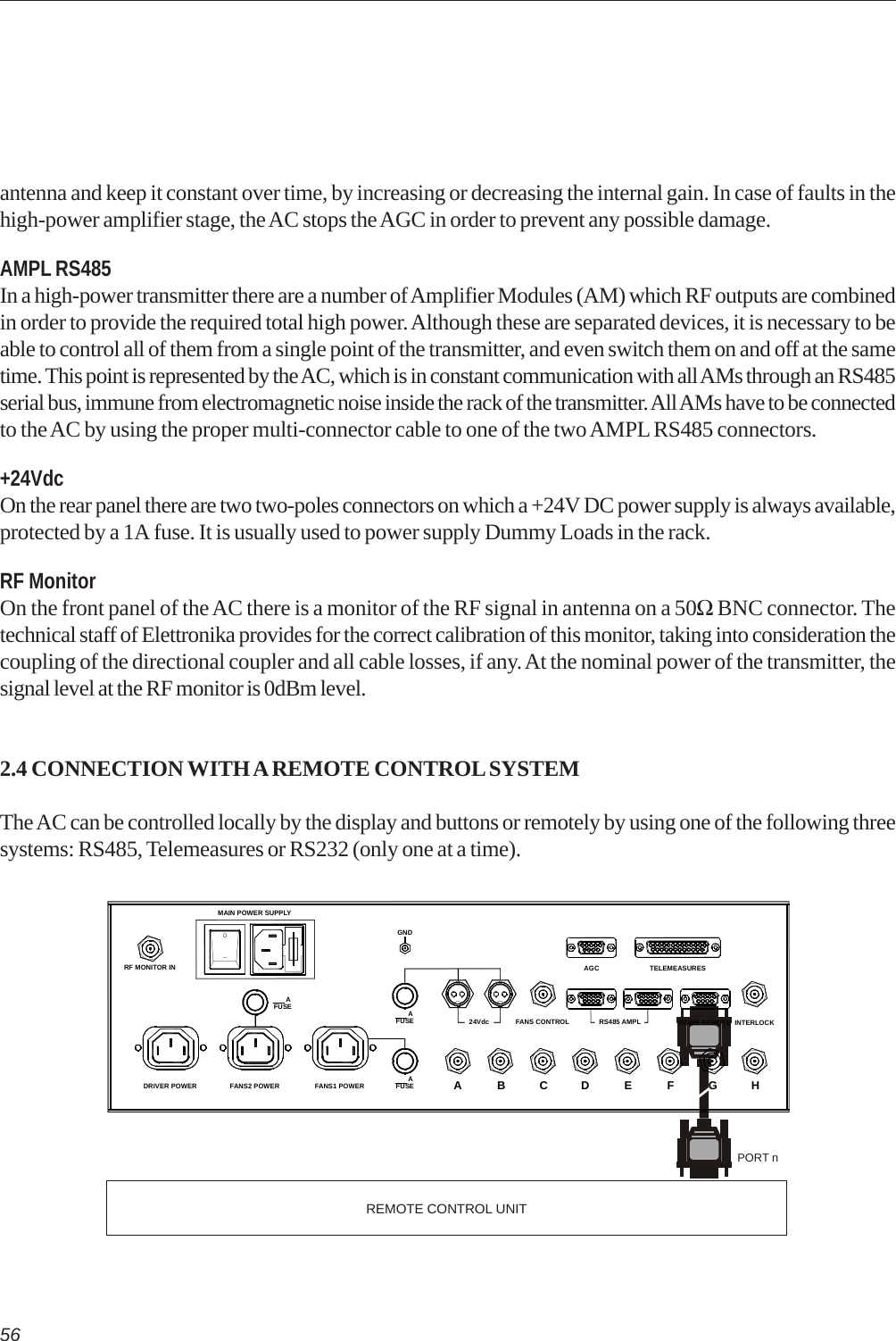
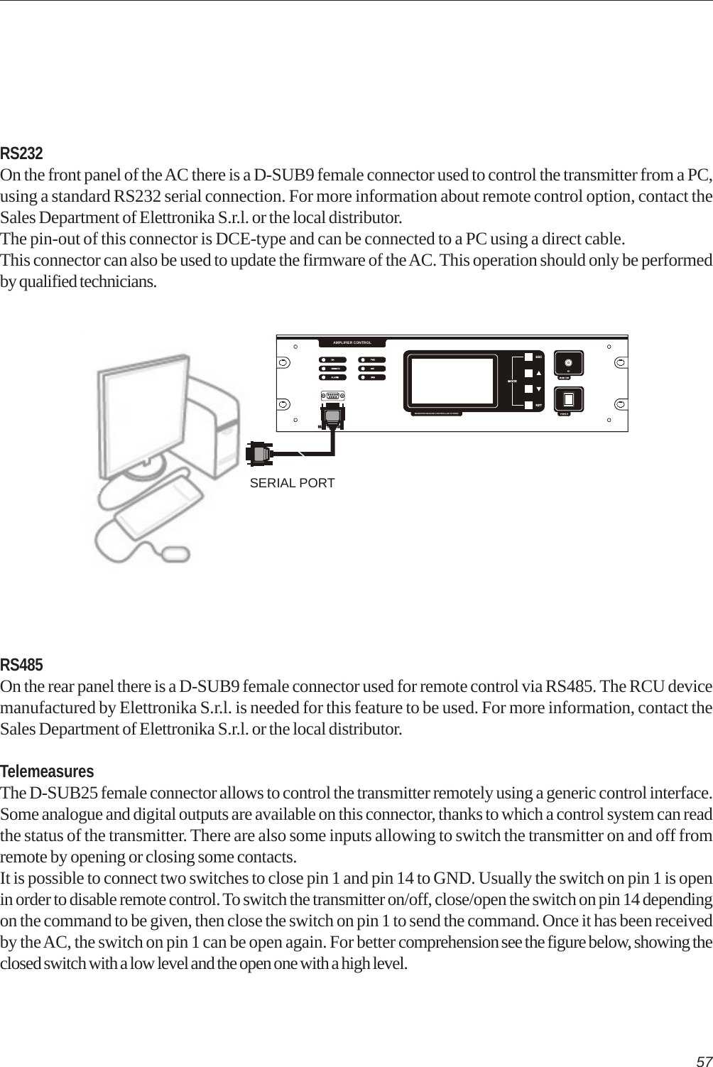
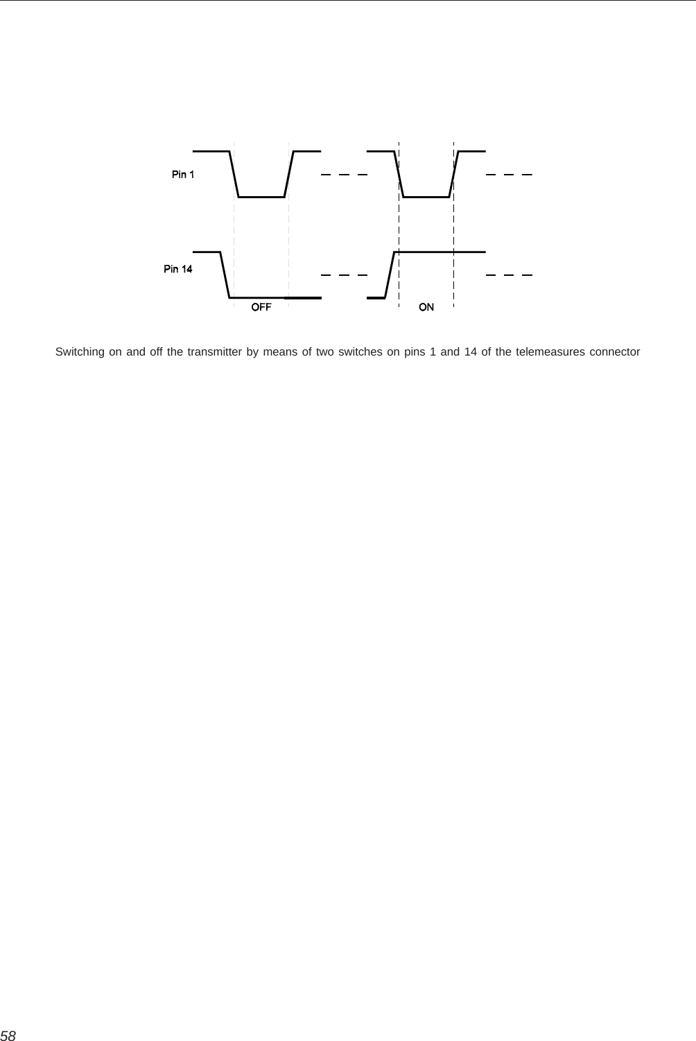
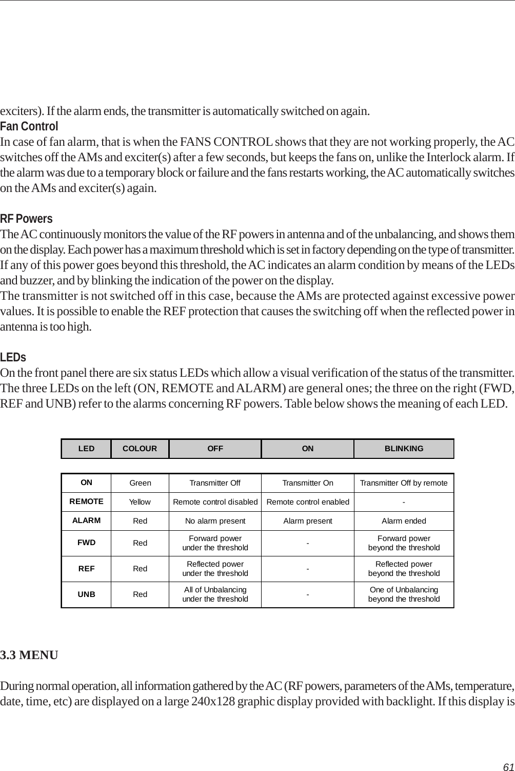
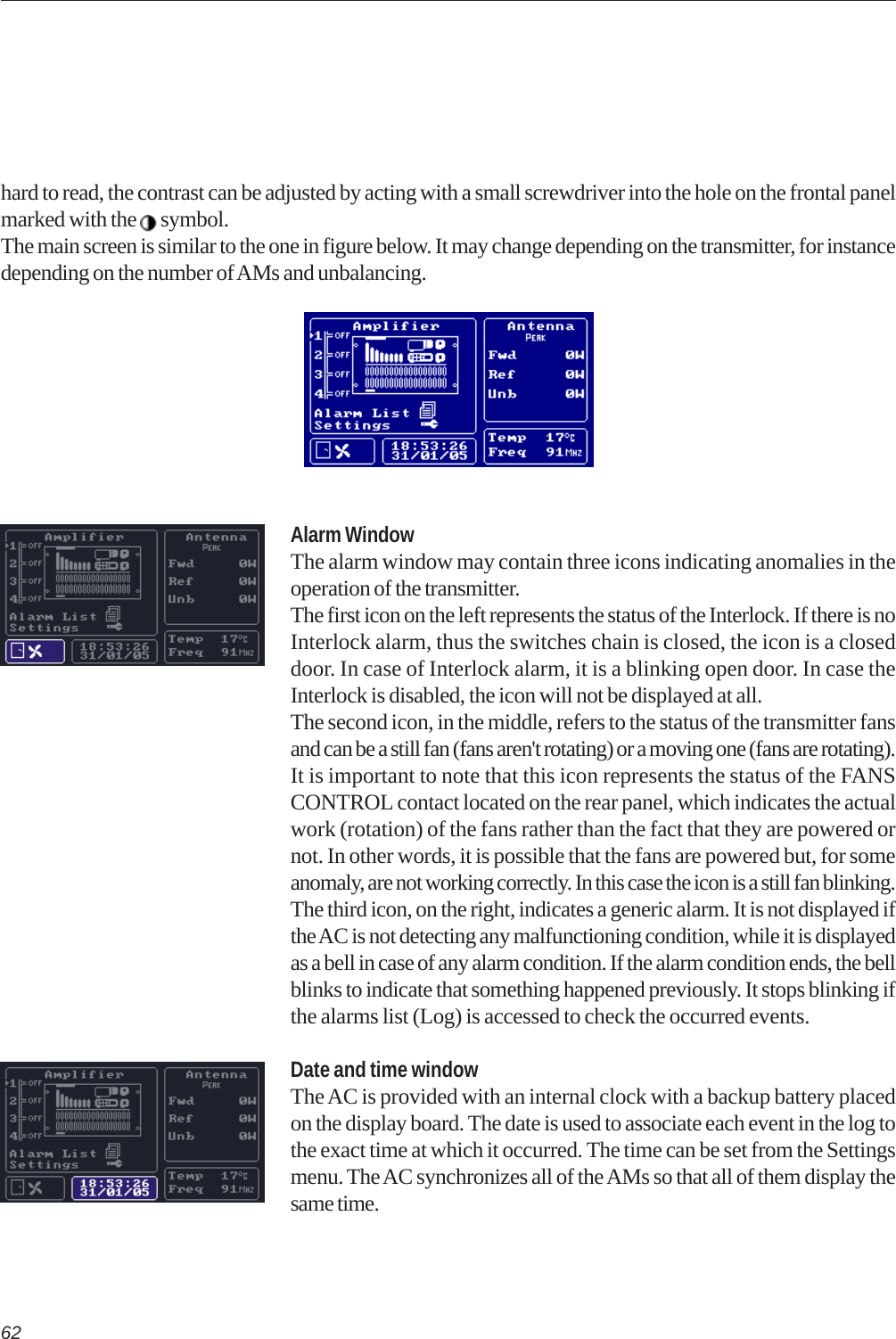
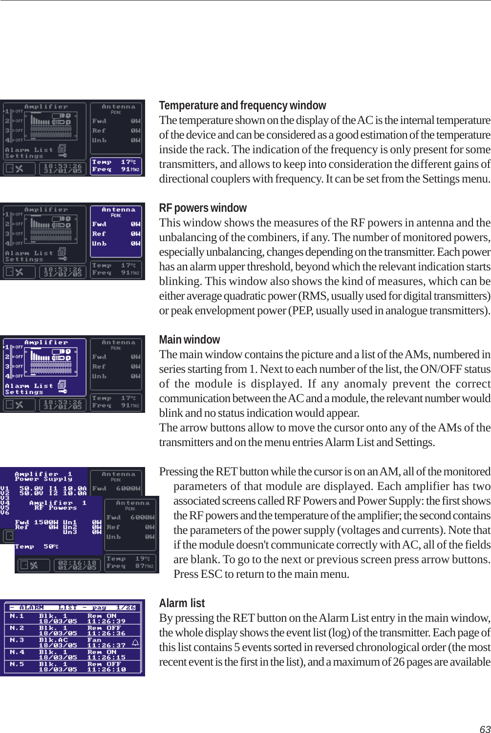
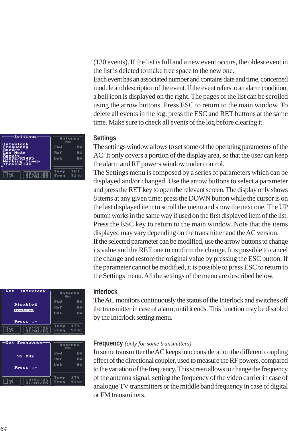
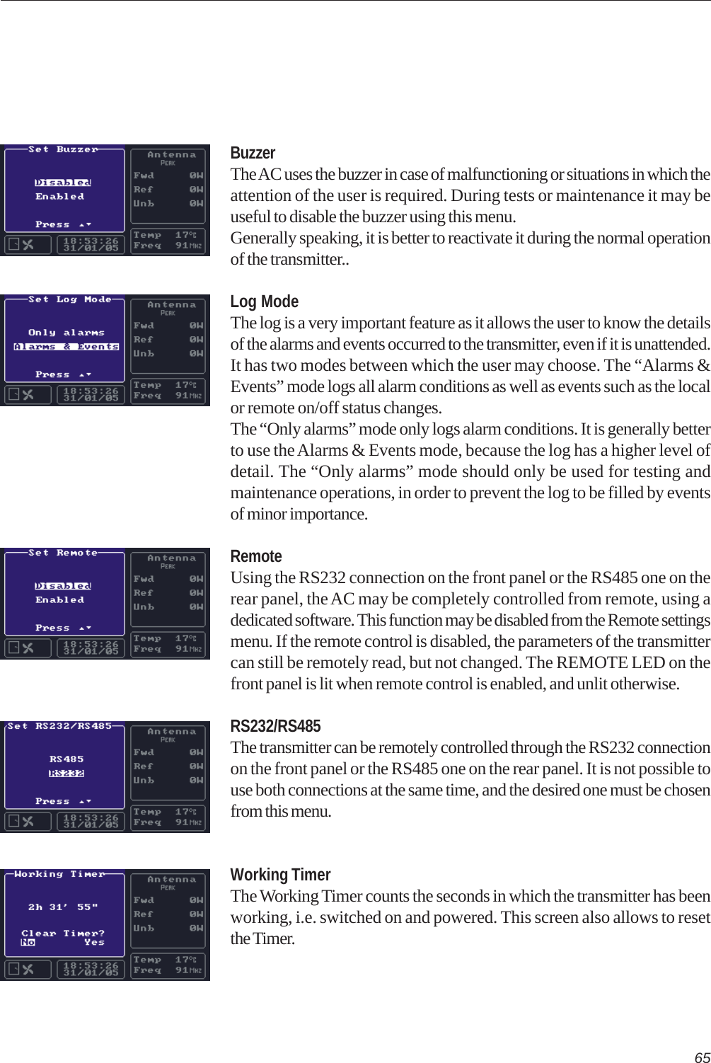
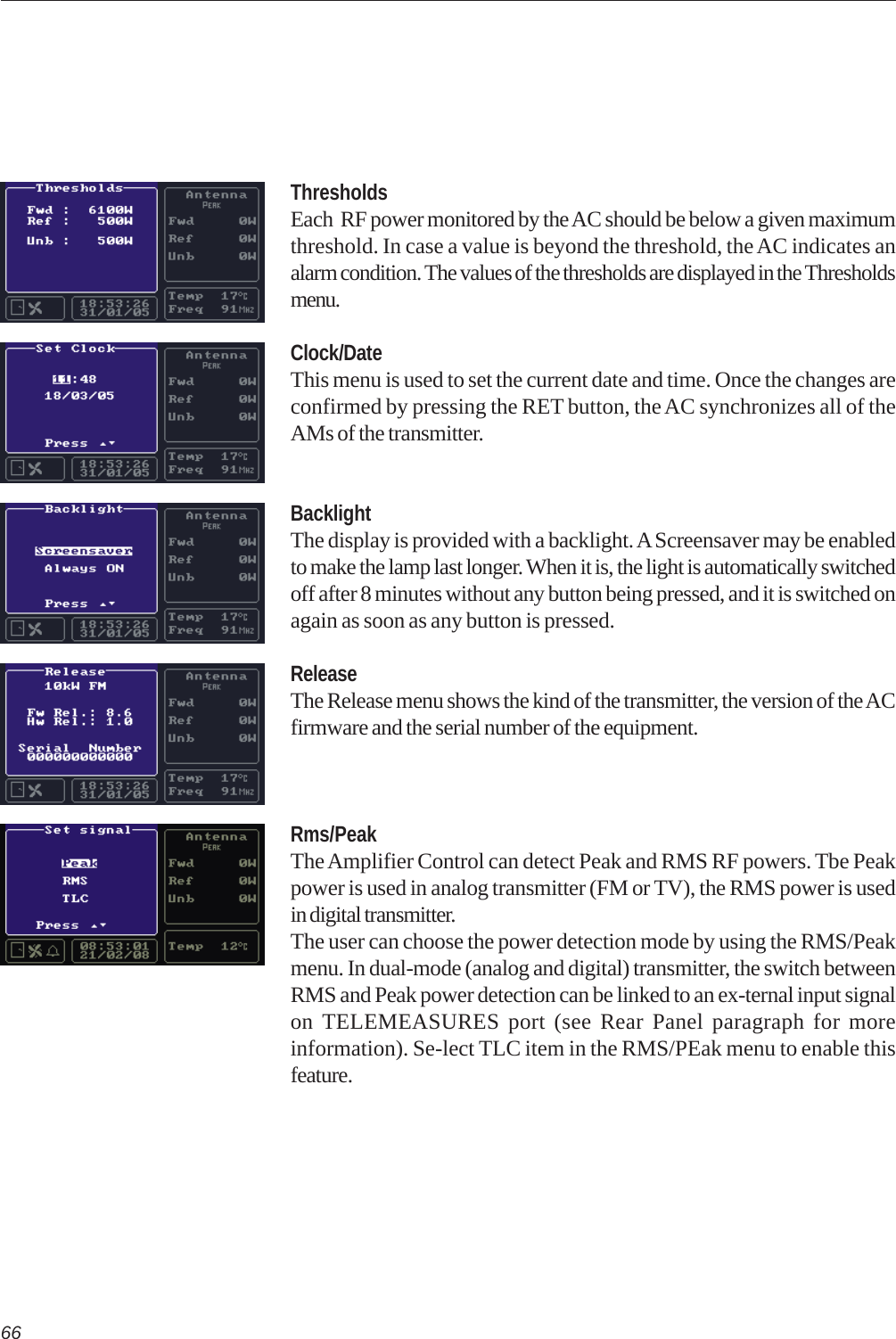
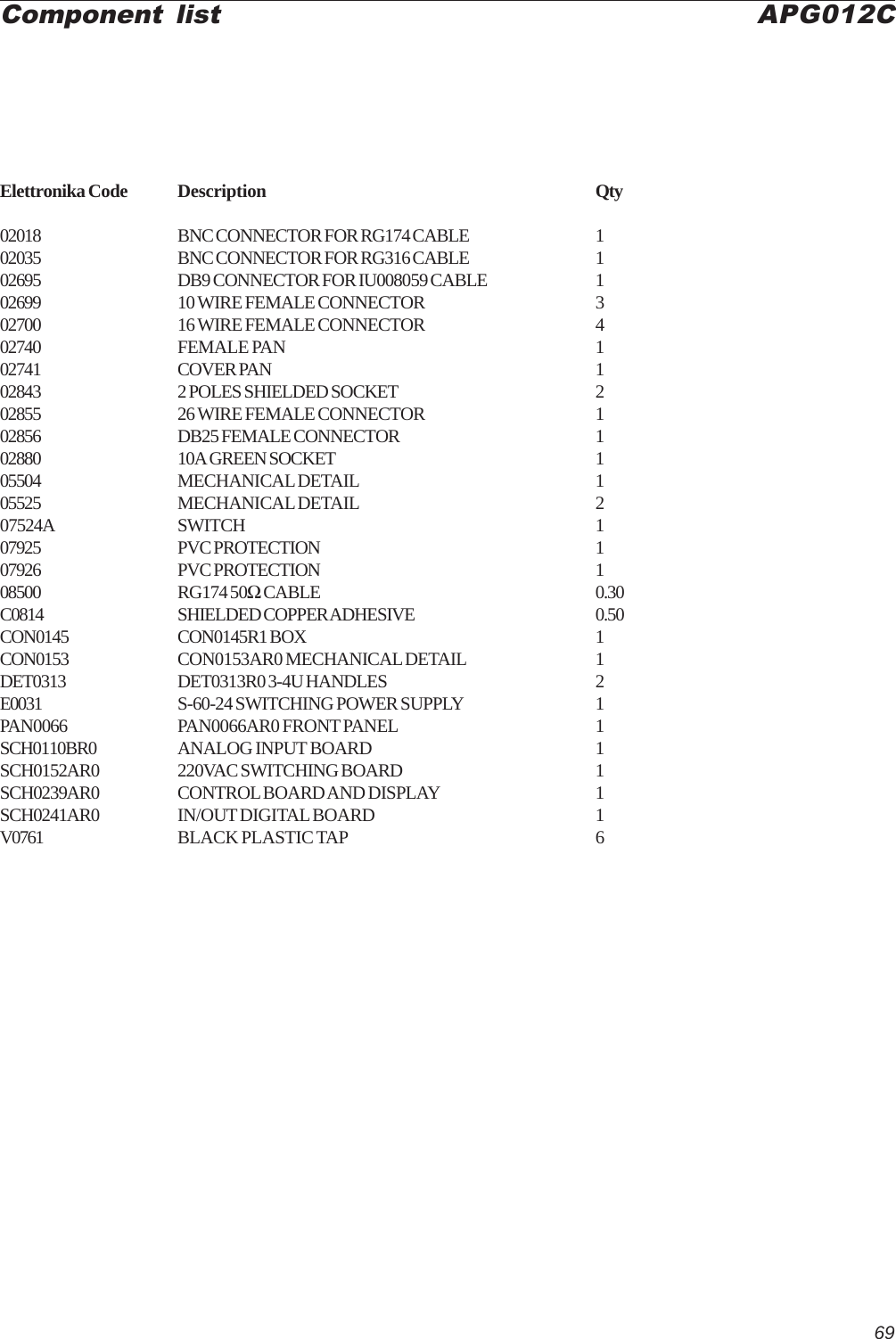
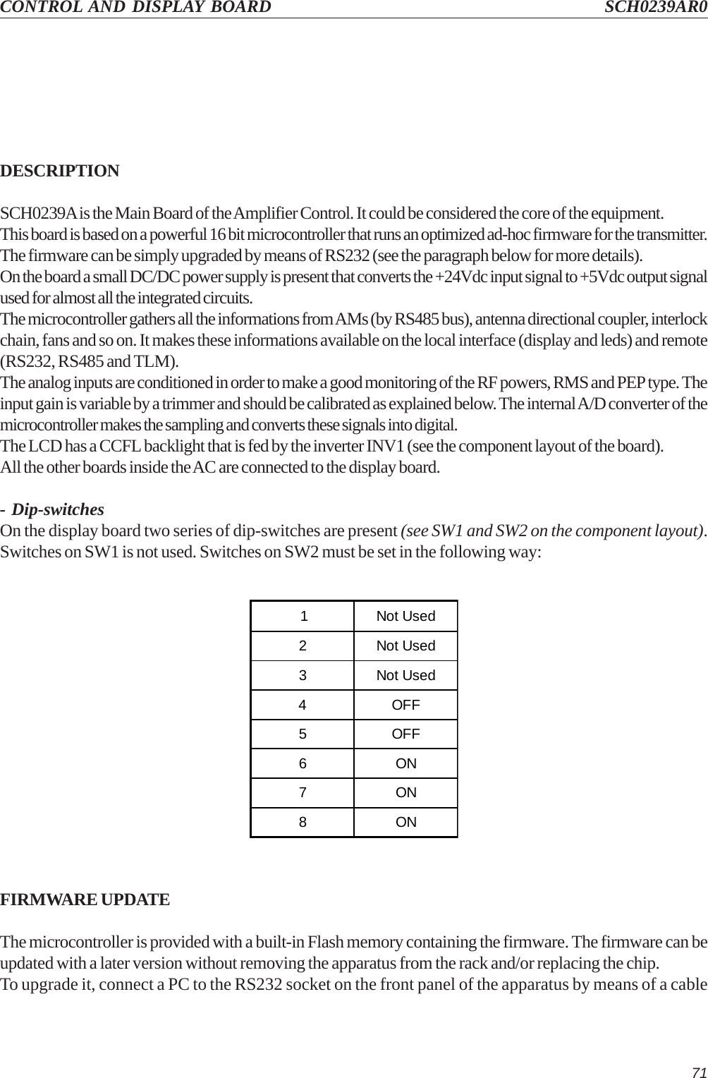
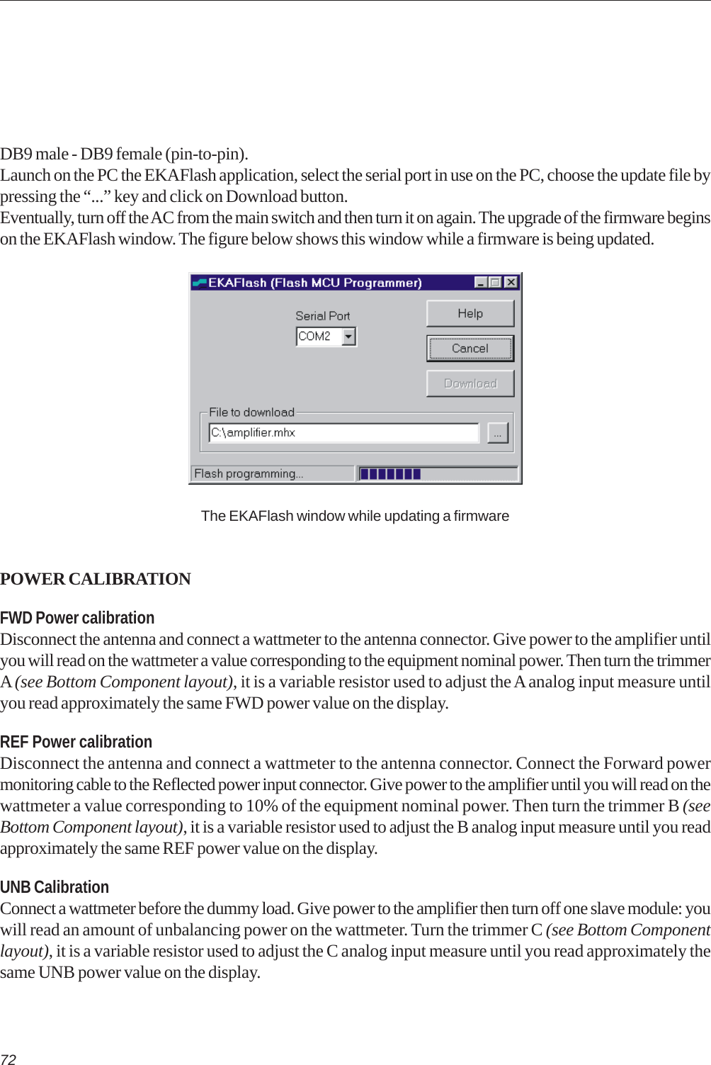
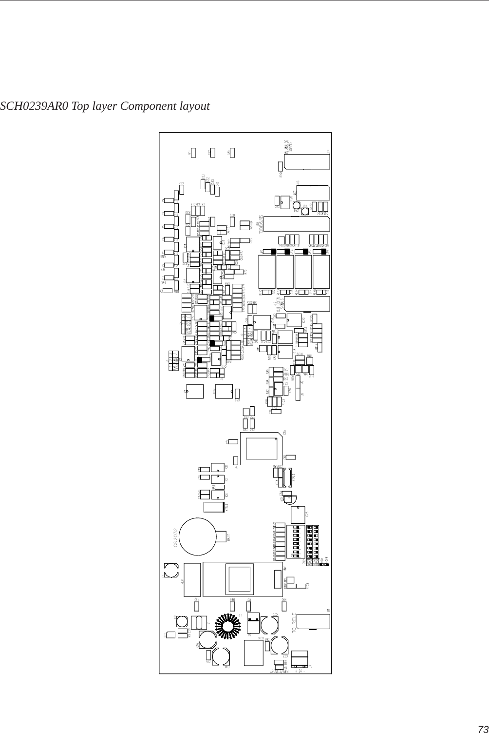
Transmitter User Manual Part 1

TXUD2000/ATSC UHF TV TransmitterCODE TXUD2000/ATSC TITLE TXUD2000/ATSC UHF TV TRANSMITTER REV      0 DATE 11/02/09
SS 96   Km 11370027 Palo del Colle (Ba) ITALYTel. +39 (0)80 626755Fax +39 (0)80 629262E-mail: elettronika@elettronika.itWeb site: http://www.elettronika.itRegistration number: IT-17686Registration number: IT-24436
3WARNINGThe apparatus described in this manual has been designed and manufactured with devices to safe-guard the users. In any case it is recommended that during any operation of installation, maintenance,miscellaneous interventions and calibrations requiring the apparatus to be switched on,THE USER TAKES ALL THEPRECAUTIONS AGAINST INCIDENTSIt is required to use the proper clothes and protection gloves in order to prevent damages from inci-dental contacts with high-voltage parts.The manufacturer declines every responsibility in case the recommendations above are not followed.IMPORTANTThe component lists attached to the relevant electrical diagrams indicate for each item the reference,the description and the type normally used.The Elettronika S.r.l. though reserves the right to use or supply as spare parts components withequivalent characteristics but of a different type, assuring anyway the optimal work of the apparatusin accordance with the specifications.The enclosed monographs are solely owned by Elettronika S.r.l.The use of anything enclosed in this technical manual without explicit authorization given by ElettronikaS.r.l. will be prosecuted by the law.The data and technical characteristics of the apparatus described in this manual are not compelling forthe manufacturer.The Elettronika S.r.l. reserves the right to make, without previous notice, modifications or updates inorder to improve the quality of the product.The general conditions of supply and sale are described in the contracts.The delivery time are in accordance with the products and quantities ordered.
4Summary of warrantyWe, ELETTRONIKA S.r.l., SS096  Km 113 Z.I.  PALO DEL COLLE (BA) ITALY, warrant to the ORIGINAL PURCHASER of a NEW  product, for aperiod of one (1) year from the date of purchase by the original purchaser (the “warranty period”) that the new ELETTRONIKA product is free of defectsin materials and workmanship and will meet or exceed all advertised specifications for such a product. This warranty does not extend to any subsequentpurchaser or user, and automatically terminates upon sale or other disposition of our product.Items excluded from this ELETTRONIKA warrantyWe are not responsible for product failure caused by misuse, accident, or neglect. This warranty does not extend to any product on which the serialnumber has been defaced, altered, or removed. It does not cover damage to loads or any other products or accessories resulting from ELETTRONIKAproduct failure. It does not cover defects or damage caused by use of unauthorized modificstions, accessories, parts, or service.What we will doWe will remedy any defect, in material or workmanship (except as excluded), in our sole discretion, by repair, replacement, or refund. If a refund iselected, then you must make the defective or malfunctioning component available to us free and clear of all liens or other encumbrances. The refund willbe equal to the actual purchase price, not including interest, insurance, closing costs, and other finance charges less a reasonable depreciation on theproduct from the date of original purchase. Warranty work can only be performed at our authorized service centers or at our factory. Expenses inremedying the defect will be borne by ELETTRONIKA, including one-way surface freight shipping costs within the United States. (Purchaser must bearthe expense of shipping the product between any foreign country and the port of entry in the United States and all taxes, duties, and other custom’s fee(s)for such foreign shipments).How to obtain warranty serviceYou must notify us of your need for warranty service not later than ninety (90) days after the expiration of the warranty period. We will give you anauthorization to return the product for service. All components must be shipped in a factory pack or equivalent which, if needed, mayDesclaimer of consequential and incidental damagesYou are  not entitled to recover from us any consequential or incidental damages resulting from any defect in our product. This includes any damageto another product or products resulting from such a defect.Warranty alterationsNo person has the authority to enlarge, or modify this warranty. The warranty is not extended by the lenght of time for which you are deprived ofthe use of the product. Repairs and replacement parts are provided under the terms of this warranty shall carry only the unexpired portion of thiswarranty.Design changesWe reserve the right to change the design of any product from time to time without notice and with no obligation to make corresponding changes inproducts previously manufactured.Legal remedies of purchaserThere is no warranty which extends beyond the terms hereof. This written warranty is given in lieu of any oral or implied warranties not containedherein. We disclaim all implied warranties, including without limitation any warranties of merchantability or fitness for a particular purpose. No actionto enforce this warranty shall be commenced later than ninety (90) days after expiration of the warranty period.Warranty for electronic tubesThe warranty applied for electronic tubes is the one given by the manufacturer of the tube. In the event that the product shows anomalies within thedeadline of the validity of the warranty given by the manufacturer of the product itself, the buyer will have to return it to the seller with the neededdocuments and the written description of the defect. The seller will ship the broken tube to the manufacturer in order to effect the necessary technicaltests to find out the cause of the anomaly. Meanwhile the buyer of the tube who needs to use, and as such to replace immediately the product, will haveto buy a new one and provide to the relevant payment, further to the issuing by the seller of a regular commercial invoice. After the adequate tests madeby the manufacturer, should the result be positive, that is confirm the defect in manufacturing, the seller will issue a regular credit note in the name ofthe buyer and return the amount paid. Should the result be negative, that is detect a negligence in the installation or use by the buyer, he will have noright against the seller.Warranty
5INTRODUCTIONThe apparatus described in this manual is the latest of this series, offering high performances, remark-able reliability and a wide range of characteristics, it all at a competitive cost.Its is easy to install and use. It only takes to follow the installation procedure as shown in this manual:after having removed all from the package, you only have to follow step by step the description in thevarious sections.Before starting to use the apparatus, remember to:read  carefully  the  general  safety  information contained in this section;follow the  instructions  for  the  installation and set up of the apparatus;read all the remaining  sections  of  this  manual in order to know well the apparatus and learnhow to obtain  the  best  of  its  characteristics.CONTENTS OF THE MANUALThe chapter composing this manual contain all the information concerning the use of the apparatus.For more information refer to ELETTRONIKA S.r.l.This manual is made up of different chapters, each made up of various sections.
6WARNING!The currents and voltages in this equipment are dangerous!Personnel must at all times observe safety regulation!This manual is intended as a general guide for trained and qualified personnel who are aware of thedangers inherent in handling potentially hazaedous electrical and electronic circuits.It is not intended to contain a complete statement of all safety precautions which should be observed bypersonnel in using this or other electronic equipment.The installation, operation, maintenance and service of this equipment involves risks both to personneland equipment, and must be performed only by qualified personnel exercising due care.Elettronika S.r.l. shall not be responsible for injury or damage resulting from improper procedures orfrom the use of improperly trained or inexperienced personnel performing such tasks.During installation and operation of this equipment, local building codes and fire protection standardsmust be observed.WARNING!Always disconnect power before opening covers,doors, enclosures, gates, panels or shields.Always use grounding sticks and short out highvoltage points before servicing. Never makeinternal adjustments, perform maintenance orservice when alone or when fatigued.Do not remove, short-circuit or tamper with interlock switches on access covers, doors, enclosures,gates, panels or shields.Keep away from live circuits, know your equipment and don’t take chances.WARNING!In case of emergency ensure that power has been disconnected.
7A - AIRWAYIf unconscious, open airway lift up neck, pushforehead back, clear out mouth if necessary,observe for breathing.Treatment of electrical shock1) If victim is not responsive follow the A, B, C’s of basic life support.PLACE VICTIM FLAT ON HIS BACK ON A HARD SURFACEB - BREATHINGIf not breathing, begin artificial breathing. Tilthead, pinch nostrils, make airttght seal, 4 quickfull breaths. Remember mouth to mouth resuscita-tion must be commenced as soon as possible.C - CIRCULATIONCheck carotid pulse. If pulseabsent, begin artificial circulation. Approx. 80sec.: 1 rescuer, 15 compressions, 2 quick breaths.Approx. 60sec.: 2 rescuers, 5 compressions, 1 breath.NOTE: DO NOT INTERRUPT RHYTHMOF COMPRESSIONS WHEN SECOND PERSONIS GIVING BREATH.Call for medical assistance as soon as possible.
82) If victim is responsive:- keep them warm;- keep them as quiet as possible;- loosen their clothing (a reclining position is recommended).FIRST-AIDPersonnel engaged in the installation, operation, maintenance or servicing of this equipment are urgedto become familiar with first-aid theory and practices. The following information is not intended to bea complete first-aid procedure, it is brief and is only to be used as a reference. It is the duty of allpersonnel using the equipment to be prepared to give adequate Emergency First Aid and thereby pre-vent avoidable loss of life.TREATMENT OF ELECTRICAL BURNS1) Extensive burned and broken skin.- Cover area with clean sheet or cloth (cleansed available cloth article);- do not break blisters, remove tissure, remove adhered particles of clothing, or apply any salve orointment;- treat victim for shock as required;- arrange transportation to a hospital as quickly as possible;- if arms or legs are effected keep them elevated.NOTEIf medical help will not be available within an hour and the victim is conscious and not vomiting, givehim a weak solution of salt and soda: 1 level teaspoonful of salt and 1/2 level teaspoonful of bakingsoda to each quart of water (neither hot or cold).Allow victim to sip slowly about 4 ounces (half a glass) over a period of 15 minutes.Discontinue fluid if vomiting occurs (do not give alcohol).2) Less severe burns - (1st & 2nd degree).- Apply cool (not ice cold) compresses using the cleansed available cloth article;- do not break blisters, remove tissue, remove adhered particles of clothing, or apply salve or ointment;- apply clean dry dressing if necessary;- treat victim for shock as required;- arrange transportation to a hospital as qickly as possible;- if arms or legs are affected keep them elevated.
9Further to the directives issued by the European Community, 2002/95/CE, 2002/95/CE and 2003/108/CE, and to the Italian Decree of Law n° 151 dated 25 July 2005, this is to inform the customers of ElettronikaS.r.l. living within the boundaries of the European Community about the following obligations:1) It is forbidden to trash RAEE products (which includes all broadcasting products which are not expresslylabelled as lead-free) along with normal wastes;2) Such devices must be brought to proper centres able to perform the adequate processing in order torecycle their parts where possible and dispose of the raw materials contained therein;3) For equipment purchased from Elettronika after the 13th of August 2005, the gathering, transport, processing,recycle and disposal operations are responsibility of Elettronika who will bear all related expenses;4) For equipment purchased from Elettronika before the 13th of August 2005 , the gathering, transport,processing, recycle and disposal operations are responsibility of Elettronika, who will bear all related expenses,only if you are purchasing from us new equipment in substitution of the disposed one;5) Electric and electronic devices contains lead in soldering, cables, etc. This substance pollutes the environmentand may be accumulated in the organism of plants and mammals. It is dangerous for humans because it mayaffect blood, bone marrow, peripheral and central nervous system and kidneys, causing anaemia,encephalopathies (e.g., convulsions), peripheral neuropathies, cramps of the abdomen and kidney damages.Besides it affects human reproduction and growth.These devices also contain mercury. From the environmental point of view, this substance is highly toxic foraquatic life, and can be accumulated in the organism of fish.Long-term damages to humans can affect the central nervous system and the kidneys, producing irritability,emotional instability, tremors, damages to the mind and the memory, language disorders. It may also irritateand whiten the gums, and its effects may be cumulative. Based on tests on animals, it may affect the humanreproduction or growth.There is also chrome, which may result in irritation of the eyes and respiration system.Cadmium is also present. In humans it may damage lungs, due to repeated or prolonged contact with its dust,and kidneys. It may cause cancer.6) The symbol below marks the devices which cannot be disposed of along with normal wastes, as stated in1) and 2) above.7) The payment of fees is foreseen for the non-allowed disposal of such devices.Communication N°1 -2002/95/CE - RoHS Directive
10This page is intentionally blank
11TXUD2000/ATSCUHF TV TRANSMITTERUser’s manual
12TXUD2000/ATSC UHF TV TRANSMITTERDESCRIPTIONThe TXUD2000/ATSC belongs to the High Power UHF products family of Television Transmitters fully inLDMOS solid state technology.The TXUD2000/ATSC series represents the 2kW ATSC TV transmitter operating in the UHF Band forCommon amplification process (separate amplification available) of the Video and Audio carriers and forDigital TV signals of different standards. This transmitters family has been designed to offer to the customerhigh performances, high reliability and greater simplicity in their operation and maintenance procedures.The Video and Audio signal processing is provided for all Analogue and Digital TV Standards and all types ofAudio applications (Mono and Dual Sound - NICAM) together with colour systems such as PAL - NTSC -SECAM. The transmitter ensures optimal performance also with Digital TV signals (DVB-T, ATSC, DTMB,etc.). Thanks to the amplitude and phase pre-correction circuit, it is possible to cancel the distortions in theoutput stage, thus cutting down the operating costs. The RF transposition in the driver is carried out by asynthesizer with various possibilities of accuracy and stability as well as precision offset locked by internal orexternal frequency reference.When equipped with a dual-mode exciter (Analogue and DVB-T), the transmitter can quickly and easilyswitch from analogue broadcasting mode to DVB-T broadcasting mode (and vice versa), to enable acomfortable operation during the transition period to the full-digital broadcasting time.The RF Amplifier is made up by four RF Amplifier Modules installed in a power rack; the modules arededicated for the Video and Audio carriers common amplification and for Digital TV amplification. Theamplifiers employ solid state LDMOS technology in order to obtain wide band, reliability, and high efficiency.Each RF module has a built-in switching-mode power supply unit, self-protected against overcurrents andovervoltages, as well as overtemperature and VSWR for RF parameters. The cooling system is fully containedinto the transmitter. The Amplifier Control unit provides full management of the transmitter without the presenceof the operator, the system includes a central controller and several peripheral units installed in each RFmodule and rack. Controller and peripherals are connected by a RS485 full-duplex bus.Power supply output voltages and currents, Forward and Reflected Powers of any single power amplifier aremonitorized by Amplifier Control unit.In that way there is a single interface point between user and all the transmitter. The operator inter-face ismade by a high resolution LCD graphic display and a simple keyboard, the menu is very friendly and easy touse.The Amplifier Control unit can be fully controlled in 'remote' mode via link or via modem in RS232 or otherinterface.The equipment design allows the soft degradation (RF power loss) for several transistors faults.
13TECHNICAL CHARACTERISTICSRF SECTIONAnalog OperationFrequency Range ............................................................................................................................................. 470 - 860MHzOutput Power .......................................................................................................................................................... 5kW PEPGain (±2) ......................................................................................................................................................................... 27dBVideo / Audio Power Ratio ...................................................................................... 10/1 single sound - 20/1/0.2 dual soundOut Stage Technology ............................................................................................................................Solid State LDMOSVideo / Audio Amplification ..................................................................................................................................... CommonStandards ................................................................................................................................................................ G, K, I, MSound Transmission .................................................................... FM single sound - Dual sound coding IRT - NICAM 728Harmonics and Suppression Emission ..................................................................................... In compliance with CCIR rec.Intermodulation Products from Video and Audiio....................................................................................................... < 50dBFrequency Stability .........................................................................................................................2.5ppm (option 0.05ppm)RF Input Connector ................................................................................................................................................ N FemaleRF Output Connector........................................................................................................................................... EIA 1+5/8”Digital OperationOutput Power (DVB-T) ...................................................................................................................................... 1200W RMSOutput Power (ATSC) ........................................................................................................................................ 2000W RMSDVB-T Modes ......................................................................................................... All the modes listed in ETSI EN 300 744DVB-T MER ....................................................................................................................................................... > 33dB RMSDVB-T Shoulders Attenuation (After non-critical mask 6-cavity filter) ............................................................. > 40dB RMSDVB-T Output Spectrum .............................................................................................................Compliant ETSI EN 300 744ATSC Symbol Rate ...................................................................................... 10.76MBaud/s (Compliant to ATSC Doc. A/53)ATSC SNR ......................................................................................................................................................... > 27dB RMSATSC Shoulders Attenuation (After simple mask cavity filter ref. total output power) ..................................... > 46dB RMSATSC Output Spectrum ......................................................................................................... Compliant to ATSC Doc. A/64VIDEO SECTIONVideo Input ........................................................................................................................................... BNC 75Ω ConnectorNominal Input Level ............................................................................................................................................. 1Vpp ±6dBReturn Loss................................................................................................................................................................. > 30dBDC Restoration ........................................................................... Clamped to the blanking level without affecting the burstWhite Limiter ............................................................................... At 90% picture signal without affecting the chrominanceTransmission characteristicsSideband Spectrum Response .....................................................................................................According to the standardAmplitude Frequency Response .................................................................................................According to the standardGroup Delay variation without receiver pre-correction and TV demodulator flat ..................................................... < ±35nsNon Linearity Distortion (10 to 75% mod.) .................................................................................................................... < 5%Differential Gain (10 to 75% mod.) .................................................................................................................................. < 5%Differential Phase (10 to 75% mod.) .................................................................................................................................< 5°Signal to random noise ratio (weighted 0.2 to 5MHz) ................................................................................................. > 60dBBlanking Level Variation ................................................................................................................................................ < 2%2T k Factor ..................................................................................................................................................................... < 2%
14AUDIO SECTIONNominal Input Level (±50kHz dev.) ................................................................................................................... -10 to +8dBmInput Impedance ............................................................................................................................................ 600Ω balancedPre-emphasis .................................................................................................................................................................. 50µsTransmission characteristicsAmplitude Frequency Response ......................................................................................................... 40 to 15000Hz ±0.5dBTotal Harmonic Distortion ........................................................................................................................................... < 0.5%FM Signal to noise ratio (referred to ±50kHz dev. f = 400Hz) ....................................................................> 60dB (weighted)AM Signal to nokise ratio ............................................................................................................. > 50dB (referred to 100%)AM Synchronous Modulation ..................................................................................................... > 40dB (referred to 100%)METERINGOutput Forward Power (Peak or RMS)Output Reflected Power (Peak or RMS)Unbalance Power (last unbalance load in output combiner)Transmitter TemperaturePower Amplifier Forward Power (Peak or RMS)Power Amplifier Reflected Power (Peak or RMS)Power Amplifier Input Power (Peak or RMS)Power Amplifier Heatsink TemperaturePallet CurrentPower Supply VoltageWorking TimerINDICATIONSCooling Blower Working (with icon on front display)Transmitter Interlock (with icon on front display)Alarm (with red LED on front panel)Transmitter ON/OFF (with green LED on front panel)Remote ON/OFF (with orange LED on front panel)Input Mains Phase Missing (with green LED on Power Control panel)PROTECTIONSMains Phase LackOutput Forward PowerOutput Reflected PowerRack Cooling FailurePower Amplifier Forward PowerPower Amplifier Reflected PowerPower Amplifier Heatsink TemperatureModule CurrentPower Supply VoltageREMOTE CONTROL SECTIONParallel Interface ........................................................................................................................... ON/OFF, Alarms, InterlockSerial Interface ...................................................................................... RS232 or RS485 (Full monitoring and management)
15GENERALPower Supply Voltage ................................................................................................... 3P+N 380V ±15%, 3P+N 230V ±15%Power Supply Frequency ........................................................................................................................................ 50 - 60HzPower Factor .................................................................................................................................................................> 0.98Analog Power Consumption (Black) ....................................................................................................................... 13.45kVADigital Power Consumption (DVB-T) .......................................................................................................................... 9.0kVADigital Power Consumption (ATSC) ......................................................................................................................... 10.2kVAHousing .........................................................................................................................................................1 Rack 19”-42UWeight (Amplifier / Rack)................................................................................................................................. 485kg / 500kgAirFlow ................................................................................................................................................................... 2500m3/hTemperature ..................................................................................................................................................... -5°C to +45°CIsolation Transformer (Power / Weight)...........................................................................................................20kVA / 250kgSpecifications and characteristics are subject to change without notice
16INSTALLATION REQUIREMENTSThis section explain how to install and configure the transmitter for your location All internal switching andsetup should be done by qualified service person.PARAMETER REQUIREMENTSTRANSMITTERROOM The room should be clean and free of dust. The building floorshuold be able to support a load capacity >1000kg/m2INSTALLATIONAREAThe transmitter should be installed to have space around enoughfor ventilation and for maintenance actions to be allowed.The minimun requirement space is  one meter outer boundary oftransmitter.TEMPERATURE The transmitter is designed to work from -5° up to 45°C, anywayto ensure long life is better to keep the room temperature lowerthan 35°C.ELECTRICALPLANTThe transmitter power consumption is <10.2kVA (13.45kVA inanalog mode), we suggest to design the main power linecapacity increased by at least  more than 50%.MAINS SYSTEM The mains system should be three phase with neutral. Thetrasmitter is available in two different mains voltage models for380VAC and 230VAC system.AIR COOLING The outlet air should be convoyed out of the room by suitable ducts(the transmitter air output adapters has a diameter of 320mm).The air flow required is 2500m3/h.ANTENNAThe transmitter RF output interface is EIA 1+5/8” (others interfacecan be supplied on request in order to match the antenna feederor combiner input). The RETURN LOSS of the  system should begreater than 27dB in the operation channel.Note: the standard cooling system is supplied with internal ventilation system, air inlet and outlet areon the top. Other different installations can be proposed for various air connection arrangements.
17SWITCH ON PROCEDUREBefore to switch on the Transmitter is extremely important to check:- The right connections for the RF system (antenna or external combiner) and take greatest care for the Innerin each coaxial connections;- the right connections with the Mains Power Supply network, the Neutral line must be present and connected,and the correspondence with the voltage nominal value request;- the right working of the earth-ground connections system, for people safety and transmitter right operation;- the right connections inside the transmitter with input/output RF cable to/from amplifier block and combiner/divider system, if for transport or installation reason you had disconnected them before.To follow with first switch on please follow the below indications:- Set in OFF position all the frontal switch, Main, Amplifier Control and Amplifiers Block;- turn ON the Mains and the Amplifier’s switch. The Amplifier Control checks the communications with theamplifier block. If the communication is ok you can turn ON the Amplifier Control, now automatically therack’s blowers and the exciter are switched ON;- give little power in to the amplifier and check if all the indicator are in the right situation (no reflected, nounbalance on the Amplifier Control, more or less the same indication for current and power for all theamplifiers block);- increase the power slowly slowly. At rated maximum output power some watts might be shown as ReflectedPower due to isolation of directional coupler or return loss from antenna system.EXCITER DESCRIPTIONThe ATSC TRANSMITTER is an 8-VSB ATSC professional exciter, designed for the most demandingdigital TV broadcasting applications. It integrates a modulator module with up-to-date FPGA technology andadvanced digital signal processing algorithms in order to generate an absolutely accurate output 8-VSB signal,with exceptionally optimized modulation and the output filtering techniques.Very high linearity performances are possible thanks to very careful RF design over the entire VHF and UHFbands and with an optimal digital precorrection engine working simultaneously in the time and frequencydomains. A high degree of reliability is guaranteed, moreover, by the use of oversized cooling devices and bycontrol circuits operated by modern microprocessor technologies. The ATSC TRANSMITTER can be usedas a stand-alone 5W RMS transmitter or as a driver stage for amplifiers of greater power. The excellentspectral purity of the conversion oscillator lets the ATSC TRANSMITTER radiate an 8-VSB signal with anexcellent MER value. The ATSC TRANSMITTER is equipped with a powerful ASI/SMPTE inputs managementblock which allows to manage the Transport Stream (TS) inputs in a fully redundant configuration, thussignificantly improving the reliability of the whole broadcasting system in every operating condition.The ATSC TRANSMITTER is totally compliant to the A/53, A/54 and A/64 ATSC recommendations with6MHz output channel bandwidth, in VHF and UHF bands.
18RF AMPLIFIER MODULE DESCRIPTIONThe RF Amplifier Modules place in the TXUD2000ATSC Transmitter station are equipment designed tosimplify transport and installation. Born to ensure high working reliability they excel also for their greatperformance.Thanks to the excellent linearity of the amplifiers, achieved with the use of the state-of-the-art LDMOS(UHF) technology, these equipment allow excellent performance both with analog and digital TV signals.The design redundancy (a power supply for every MOS device), the oversized unbalanced power dummyloads, the wide input range of the switching-mode power supplies, allow a NO STOP transmission 24h perday. The temperature of the amplifiers is guaranteed by a forced air cooling system extremely noiseless.The presence of Amplifier Control that collects all measures from amplifiers and from antenna system ensurea single control point to access to all MOSFET currents, power supplies voltages, temperature of the heatsinks, amplifiers output powers together with the RF power reading of the output antenna system.A multifunctional display on the Amplifier Control makes it possible to verify all the operating parameters ofthe unit. The amplifiers in the series are remotable by wired telemetry connector or by serial communication,RS232 on front panel or RS485 on rear panel of the Amplifier Control.CHANNEL CHANGE PROCEDURETo proceed with a channel change operation, please follow the below indications:- Follow the channel change indications on users manual of the exciter;- from each RF Amplifier Modules select the new closest channel frequency;- tune the Bandpass Output Filter on new channel;- if the difference with the two channel is less than 10 you don’t need to change the power amplifier phasebalance. Otherwise, connect a digital meter to a DC Monitor (BNC) on each dummy load and keep low thevalue, by tuning the microstrip length on the input divider;- connect a Wattmeter and a Dummy Load;- set the rated output power and tune the right Forward Power indication on the Amplifier Control display;- set the output at 10% of the rated ones, swap the Forward and Reflected cable on the rear of the AmplifierControl and set the reflected indication.The 3dB Output Coupler is a wide band type and don’t need any tuning operations.DIGITAL  UPGRADEThe amplifier is ready to operate with a DVB-T signal keeping the same analogue high performance.- Replace the analogue Bandpass Filter with a digital ones (critical or not critical mask are well supported);- select the RMS Detector instead of peak one on Amplifier Control and on each power amplifier to have theright power indication and the new power alarm threshold;
19- replace the analogue Cxciter with a DVB-T ones. If you use a DVB-T Modulator with IF output you canuse the IF VEGA input;- the output power should be around 1/4 (in DVB-T mode) or 1/3 (in ATSC mode) of the analogue rated power(for example: the 5kW = 1.2kW rms in DVB-T mode or 5kW = 2.0kW rms in ATSC mode).
20Elettronika Code Description Qty Page 1/201404 BYPASSING CAPACITOR 202015 BNC CONNECTOR FOR RG58 CABLE 702408 90° 7/16” MALE-90° 7/16” FEMALE CONNECTOR 102459 EIA 1+5/8” INNER CONNECTOR 102502 SMA SOCKET FOR RG58 CABLE 302526 EIA 1+5/8” RIGID LINE 1.0002527 EIA 1+5/8” ANGLE 502791 DB9 MALE SOCKET PANEL MOUNTING 702844 2 POLES SHIELDED SOCKET 202865 4 POLES SHIELDED SOCKET 202871 DB9 SHELL 702886 3m 16A MALE/FEMALE CABLE 102893 3 WAY MALE SCREW TERMINAL 302894 3 WAY FEMALE SCREW TERMINAL 303205 HP 5082/2800 DIODE 205447 ALLOY COPPER BAR DRILLED 305448 M6 BAR METALS 106648A EIA 1+5/8” DIRECTIONAL COUPLER 106655A UHF DTV BANDPASS FILTER 106870 90° EIA +15/8” MECHANICAL DETAIL 107528A 2 POLES 16A CURRENT DEVICES 107549 4x63A CURRENT DEVICES 107550A 1P+N 500V FUSE-HOLDER 107553 220V GREEN LIGHT 107558B TIMER MODULAR FINDER 107574 63A CONTACTOR 107620 HIGH GRID 207625 EBM BLOWER 207625A 3uF CAPACITOR 207810 AC FILTER 107970 PVC PROTECTION 208504 RG58 50Ω CABLE 14.00A9029 7.5kW UHF MULTICOUPLER 1APG012C AMPLIFIER CONTROL 1APG050F 230VAC THREE-PHASE POWER CONTROL 1APT144CM AUTV/1500LD LMOS UHF TV AMPLIFIER 4C0205 MULTIPOLE CABLE 7.00C0798 MERLIN PLASTIC TAP 2CMS6006 1m 1/2” CABLE WITH 7/16” MALE CONNECTOR 4CMS6009 1.5m 1/2” CABLE WITH 7/16” MALE CONNECTOR 3CSS5011 N MALE-N MALE CONNECTOR FOR RG58 CABLE 5DET1069 DET1069R0 BLOCK FOR CONTAINERS WITH WHEELS 11DET1126 DET1126R0 EIA 1+5/8” RIGID LINE SUPPORT 2DET1183 DET1183R3 BAR SUPPORT GUIDE 12DET1184 DET1184R4 ANGOLAR SUPPORT EQUIPMENT 8Component list APT200B/ATSC
21DET1201 DET1201R1 ANGOLAR SUPPORT BOX 8DET1204 DET1204R0 GUIDE SUPPORT 2DET1205 DET1205R0 GUIDE SUPPORT AMPLIFIER CONTROL 2DET1283 DET1283R0 BAR SUPPORT BANDPASS FILTER 2DET1287R2P DET1287R2 DISTRIBUTOR NETWORK COVERAGE 1DET1288 DET1288R0 SPECIAL SPREADING GUIDE EXCITER 2DET1294 DET1294R1 GUIDE DIN DISTRIBUTION NETWORK 1DET1334R0P DET1334R0 FIXING ANGOLAR AC FILTER NETWORK 1DET1336R0P DET1336R0 FIXING PLATE FILTER NETWORK 1DET1343R2P DET1343R2 ANGOLAR SUPPORT EQUIPMENT 4DET1350R0P DET1350R0 DIN GUIDE SUPPORT POWER CONTROL 1DET1351R0P DET1351R0 SUPPORT NETWORK COVER. DISTRIB. 2DET1362R2Z DET1362R2 SUPPORT DIRECTIONAL COUPLER 1DET1367R0P DET1367R0 ANGOLAR SUPPORT EQUIPMENT 2DET1416R0P DET1416R0 SUPPORT FAN CAPACITOR 1DET1528R0P DET1528R0 BAR SUPPORT OUTPUT COUPLER 2DET1529R0P DET1529R0 FIXING DEIAL OUTPUT COUPLER 2DET1646R0P DET1646R0 CONVEYER 2FUS04 4A 500V FUSE 2MTG0143AR0 0.7+0.7+1.4kW UHF DUMMY LOAD 1MTG0149AR0 4 WAY UHF INPUT DIVIDER 1PAN0080 PAN0080R0 1U FRONT PANEL 3PAN0082 PAN0082R0 3U FRONT PANEL 1SCH0268AR0 FAN CABLE BOARD 1R0032 PLASTIC BOX FOR DOCUMENTS 1RAK0006U42 42U OMP RACK 1V0769 BLACK PLASTIC TAP 1V0929 TETRAPOLAR TERMINAL 1V0973 5 POLES AC SOCKET COVER 1V0974 AC SOCKET COVER 1V0975 CABLE HEAD 1V0976 FEMALE CONTACT 5V0989 4 WAY AC MULTISOCKET 1
22GND N TSR13425254132145313254(Optional)ATSEXCITERAMPLIFIERAPG012CCONTROL1 = CONTROL5 = R4 = S2 = N3 = T12467A1A28APD043AEXCITER(Optional)AUTV/1500LDAPT144CMAUTV/1500LDAPT144CMAUTV/1500LDAPT144CMAUTV/1500LD2 x AXIAL FANS EBMA2E 250-AM06-13FANS POWER 1DRIVER POWERGND T S RGROUND BARAPT144CM = GMAINS INPUTMAINS INPUTMAINS INPUTMAINS INPUT123 4 56 81234567FN 256-64-52MULTIPLESOCKETMAINS FILTER84P 63A/6000MAIN BREAKER4P 63A/COIL 230VCONTACTOR4A 500V 28x10mmFUSEFINDER 81.01TIMER2P 16A/6000MAIN BREAKER110/230V GREENLIGHT2X10A+GSOCKET7AUXMAINAPG050FPOWER CONTROL2-5 = L4-3 = L1 = NC = G2-5 = L4-3 = L1 = NC = G2-5 = L4-3 = L1 = NC = G2-5 = L4-3 = L1 = NC53
23A1A2A4A3L1L2L3L1 L2L3RF OUT4 WAY HYBRID SPLITTER470-860MHzDUMMY LOAD CONNECTIONSINTERCONNECTIONS CABLERF OUT RF IN RF OUT RF OUTRF INPUT CONNECTIONSRF OUTPUT CONNECTIONS
24RF MONITOR CONNECTIONRS485 AMPLIFIER CONNECTIONSFWD AND REF CONNECTIONSA4A3A2A1
25REMOTE CONTROL CONNECTIONSAGC CONNECTION
2612UNBALANCE CONNECTION24V FAN CONNECTION
27
28
29
30Elettronika Code Description Qty00173 68kΩ 1/2W RESISTOR 1202881 4 POLES MALE CONNECTOR 202882A 4 POLES 90° FEMALE CONNECTOR 202897 2 WAY MALE CONNECTOR 302898 2 WAY 90° FEMALE CONNECTOR 303060 5mm GREEN LED 307528H 1 POLE 20A 250V MAGNETO-THERMIC SWITCH 107541 10A FUSE-HOLDER PANEL MOUNTING 107543 FUSE-HOLDER PCB MOUNTING 307561B 110V RELE 307638 SWITCH 107639 EMERGENCY BUTTON 1CON0311 CON0311R0 COVER 1CON0312 CON0312R0 MULTISOCKET BOX 1DET0773 DET0773R0 MECHANICAL DETAIL 1FUS00012 COVER FUSE 3FUS2A 2A FUSE 1PAN0155R2P PAN0155R2P FRONT PANEL 1PN1286A PN1286AR2 PRINTED CIRCUIT BOARD 1V0977 AC SOCKET 1V0978 BOX 1V0979 MALE CONTACT 5Z0021 MECHANICAL DETAIL 2Component list APG050
31MAIN CONTROL BOARD SCH0398AR0SCH0398AR0 Component layoutSCH0398AR0 COMPONENT LISTPart Name/Number Description Qty. Comps.DL LEDG5 03060 03060 GREEN LED DIODE 5mm 3 DL1-3FUSE 2A-PCB 7543 7543 5x2 FUSE-HOLDER + FUSE 3 F1-3J CON KBW02_2P_M_90° 02897 + 02898 ELSAP PCB CONNECTOR 3 J3-5J CON KBW04_4P_M_90° 02881 + 02882A ELSAP PCB CONNECTOR 2 J1-2R 100R-1/2W 00139 00139 1/2W 5% RESISTOR 12 R1-12RL FINDER40.52 756A 7567A RELE 3 RLY1-3
32
33FAN CABLE BOARD SCH0268AR0SCH0268AR0 Component layoutSCH0268AR0 COMPONENT LISTPart Name/Number Description Qty. Comps.J CON HD515V/05-3PVE 02893+02894 PAN PCB CONNECTOR 4 J1-3, J8J TESTP1.3mm 07913 07913 TEST POINT 6 J4-7, J9-10
34
350.7+0.7+1.4kW UHF DUMMY LOAD MTG0143AR0DESCRIPTIONThe MTG0143A module is a load including three unbalancing loads. Two of them can dissipate 700W CW,the other up to 1400W CW.The input connector of each load is 7/16” Female. Inside the loads, Florida RF-Labs resistors are used. Themeasured Return Loss is higher than 22dB in the band from 450 to 870MHz.Besides there is an input (BNC Female connector) for each load allowing to monitor the unbalancing powerlevel on the load. This input is very useful both for testing and while changing channel.The rear panel of the load module also as other two inputs:- 2 pin shielded plug to power the SCH0404A board and the fans;- 4 pin shielded plug used for the serial cabling of the Load modules and the Amplifier Control modules in the   complete device, in order to protect it in case of failure.The following is a short description of the operation of the module. Next to the resistors there are twotransducers, LM35DT, converting a temperature measure into a control voltage. In case of unbalancingbetween the amplifiers, the RF power affects the load and the temperature of the heat sink increases. After afirst higher threshold has been passed, the control voltage, trough the SCH0404A board, enables the fans. Innormal conditions this decreases the temperature of the heat sink until it goes under a lower threshold, then thecontrol voltage disables the fans.In case the temperature should rise to about 90°C for any reason, the protection circuit is triggered andblocks the entire device.TECHNICAL CHARACTERISTICSFrequency Range 460 - 870MHzMax Power 700 - 1400WReturn Loss > 22dBPowr Supply Voltage +24VRF Input Impedance 50Ω
36FRONT PANEL11. GridREAR PANEL1 2 3 4 5 6 781. L-1 RF Input Connector 5. L-2 RF Input Connector2. Test Point 6. Test Point3. L-3 RF Input Connector 7. 24V Fan Connector4. Unbalance Connector 8. Grid
37Component list MTG0143AElettronika Code Description Qty00028A 82Ω 1206 SMD RESISTOR 300441 350W 50Ω HIGH POWER TERMINATIONS 800664 LM35DT THERMAL SENSOR 201041 1nF 50V CERAMIC CAPACITOR 401041D 1nF 1206 SMD CAPACITOR 301400 BYPASSING CAPACITOR 402010 BNC FEMALE CONNECTOR 302018 UG909 CONNECTOR FOR RGB174 CABLE 102402 7/16” FEMALE CONNECTOR 302843 2 POLES SHIELDED SOCKET 102518 SMB SOCKET FOR RG174 CABLE 103207 HSMS-2802-TR1G DIODE 305552B 3-4U HANDLE KIT 207586 24V PAPST FAN 307596 GRID FAN 308500 RG174 50Ω CABLE 0.8009419 PN419/A PRINTED CIRCUIT BOARD 2CON0009 CON0009R3 REAR PANEL 1CON0290 CON0290R0 COVER 2CON0348R1P CON0348R1P MECHANICAL DETAIL 1CON0349R1P CON0349R1P MECHANICAL DETAIL 1DET1054I DET54R1 MECHANICAL DETAIL 2DET1185 DET1185R1 MECHANICAL DETAIL 2DET1253 DET1253R2 HEAT SINK 1DET1254 DET124R2 MECHANICAL DETAIL 1DET1255 DET1255R1 MECHANICAL DETAIL 2DET1256 DET1256R1 MECHANICAL DETAIL 1DET1257 DET1257R2 DUMMY LOAD COVER 1DET1318R0P DET1318R0P MECHANICAL DETAIL 1PAN0156R1P PAN0156R1P FRONT PANEL 1PN1269AR3F PN1269AR3 700W UHF DUMMY LOAD 2PN1271A PN1271AR3 PRINTED CIRCUIT BOARD 1PN1273A PN1273AR2 PRINTED CIRCUIT BOARD 1R0012 18mm DIAMETER WHEEL 8SCH0404AR1 TEMPERATURE CONTROL BOARD 1
38DUMMY LOAD TEMPERATURE CONTROL BOARD SCH0404AR1SCH0404AR1 Component layoutSCH0404AR1 COMPONENT LISTPart Name/Number Description Qty. Comps.CC 100nF-S 01065E 01065E Y5V 0805 CAPACITOR 6 C1-2, C4-5, C7, C9CC 10nF-S 01053A 01053A SMD 0805 CAPACITOR 2 C3, C6CE 100uF50V-S 01795A 01795A ELET. SMD CAPACITOR 1 C8IC LM358M-S 04660 04660 SMD INTEG CIRCUIT 1 IC1IC LM393-S 04639 04639 SMD INTEG CIRCUIT 2 IC2-3J CON KBW02_2P_M_90° 02897 + 02898 ELSAP PCB CONNECTOR 1 J6J CON KBW04_4P_M_90° 02881 + 02882A ELSAP PCB CONNECTOR 1 J5J SMB-PCB 02516 02516 PCB CONNECTOR 1 J7J TESTPOINT-P TEST POINT 4 J1-4R 10K-S 00053C 00053C RES 1/4W 5% SMD 0805 6 R1, R6, R9, R11, R22, R34R 12K-S 00054C 00054C RES 1/4W 5% SMD 0805 4 R7, R17, R31, R36R 15K-S 00055C 00055C RES 1/4W 5% SMD 0805 4 R4, R15, R23, R35R 1K0-S 00041C 00041C RES 1/4W 5% SMD 0805 2 R19, R33R 1K8-SS 00044B RES 1/4W 5% SMD 0805 4 R2, R8, R24, R27R 1M-SS 00077B RES 1/4W 5% SMD 0805 4 R14, R16, R29-30R 220R-SS 00033D RES 1/4W 5% SMD 0805 2 R20-21R 2K0-SS 00004 RES 1/8W 1% SMD 0805 2 R10, R12R 47K-S 00061C 00061C RES 1/4W 5% SMD 0805 2 R18, R32R 4K7-S 00049C 00049C RES 1/4W 5% SMD 0805 2 R13, R28R 5K6-S 00050C 00050C RES 1/4W 5% SMD 0805 4 R3, R5, R25-26RL 40.31.24 7567C RELE 1 RLY1TR BC807 03453 03453 PNP SMD TRANSISTOR 2 TR1-2
39
40UHF DTV BANDPASS FILTER 06655ATECHNICAL DATAFrequency Range 470 - 862MHz SWR < 1.22Configuration 6 Cavities elliptical 2nd Harmonic Attenuation > 80dBBandwidth 6 to 8MHz Group Delay Variation < 250nsMax Output Power 2.5kW (rms) Temperature Stability < 1.5kHz / KInsertion Loss f(0) < 0.3dB Ambient Temperature Range -10° to +50°CAttenuation f(0) ±3.8MHz < 0.8dB (SWR 1.22), < 1dB (SWR 1.18) Weight 35kgAttenuation f(0) ±4.2MHz > 5dB (SWR 1.22), > 6dB (SWR 1.18) Working Position AnyAttenuation f(0) ±6MHz > 30dB (SWR 1.22), > 35dB (SWR 1.18) Dimensions Max 370 x 372 x 564mmAttenuation f(0) ±8MHz > 45dB (SWR 1.22), > 50dB (SWR 1.18) Output Connector EIA 1+5/8” UnflangedTUNING INSTRUCTIONSTo calibrate the filter PBN153/45-6C/58, a double-track Network Analyser is needed, in order to displaythe frequency response of the passing signal and the reflected one. The filter is composed by siz band-passcavities with coupling between intermediate cavities. Connect the filter to the Network Analyser, marking the input. Select the middle frequency of the channelrange in the middle of the screen and set a SPAN of 50MHz. Turn the coupling (4) (fig. 1) to the end. Act on the tuning rods (1) (fig. 1) until the curve is displayed at the center of the screen, then act on theinterstage couplings (2) and on the IN/OUT couplings by rotating the screw (3) to obtain a band width ofabout 8MHz. Set the instrument for a SPAN of 20MHz, move the markers to the limits of the used band (Fo ±3.9MHz).
41 Rotate the coupling (4) (fig. 1) until the notch attenuations appear and are positioned at about ±6MHzfrom the centre of the channel. Alternately proceed with all adjustments, taking into consideration that each time the IN/OUT couplings(3), the nearer tuning to the relevant coupling and the relevant interstage coupling must be shifted. Once an adaptation over 25dB has been obtained, included between the two markers at the limits of theband in use, lock the fastrening handle (4) compensating the locking rotation (anticipating it). Fasten the couplings (2). Fasten the tunings by means of a 10mm wrench, compensating each time the mechanical adjustment ofeach.Example of tuning in CH 31 Standard B 8MHz.
42
43AMPLIFIER CONTROLUser’s manualACCESSORIES
44This page is intentionally blank
45Section 1 - InformationContents:1.1 Description1.2 Technical characteristicsFront panelRear panelFront and rear panel connectorsBlock Diagram
461.1 DESCRIPTIONThe Amplifier Control (AC) module is the equipment that allows to monitor and manage from a single locationa modular transmitter, composed by several combined amplifier modules (AM). The AC continuously monitorsthe status of the AMs and highlights any anomaly, it monitors the powers in antenna (forward and reflected)and the unbalancing, if any, showing all of the parameters on the display and through the status LEDs. It ispossible to power supply the fans of the rack directly by the AC, which constantly monitors their operation,thus protecting the AMs and the other components in the rack in case of failure. Even the exciter(s) can bepowered directly by the AC, so that it can be switched on or off along with the amplification stage.The human-machine interface (HMI), intuitive and user-friendly - most of all thanks to the large graphicdisplay which covers the most of the front panel and to the six status LEDs -, the noise-immune RS485connection with the AMs, the possibility to connect a series of switches to an Interlock input and the remotecontrol option make the AC a reliable, as well as easy to use, device to be used in low and high-power, FMand TV, analogue and digital, combined and separated transmitters.In most cases the AC is already installed into the transmitter, wired and calibrated, so that the user can use itwithout having to worry about technical details. Anyway, Section 2 of this manual covers the main informationabout installation and external connections. For additional technical information, contact the Customer Serviceof Elettronika S.r.l. or the local distributor. Section 3 describes the operation of the AC and everything theuser can do with it. Read this section carefully before using the device.AMPLIFIER CONTROL
471.2 TECHNICAL CHARACTERISTICSHuman-Machine Interface- 240x128 graphic display with CCFL backlight- 3 general LEDs (ON, REMOTE, ALARM)- 3 alarm LEDs for RF powers (FWD, REF, UNB)- 4 push-buttons (ESC, RET, UP, DOWN)Alarms resulting in the transmitter being switched off- Fans rotation (about 10 second delay)- Interlock (immediate, can be disabled)- Antenna Reflected power (if configured)Alarms not resulting in the transmitter being switched off- Lack of communication with an Amplifier Module- Amplifier module locally switched off- Alarm on amplifier module- Power in antenna or unbalancing beyond the threshold (Reflected power alarm can be configured to switch off the trans-   mitter)Connections on the front panel- RF Monitor on 50Ω BNC connector (0dBm at the nominal power)- RS232 on DCE-type D-SUB9 female connector, for control via PC or firmware updateConnections on rear panel- RS485 on two D-SUB9 female connectors for the connection with the Amplifier Modules- RS485 on D-SUB9 female connector for the connection with an optional remote control device*- Telemeasures (Forward power, Reflected power, Unbalancing, Alarm) and telecontrol (ON/OFF) on D-SUB25 female connector- Up to 8 RF powers can be monitored on BNC connectors- Fans rotation control on BNC connector- Alarm on the opening of a series of switches (Interlock) on BNC connector- Power supply +24Vdc available on two 2-poles connectorsMiscellaneous- Real-time clock with CR2032 lithium backup battery (nominal voltage 3V, nominal capacity 210mAh)- Alarm and event list up to 130 entries- 100-240Vac 50/60Hz Power Supply- 19”-3U Cabinet, deep 260mm- 6kg Weight- Operating Temperature -5° to +45°C- Relative Humidity 20% - 90%- Altitude up to 2500m* For more information contact the Sales Department of Elettronika S.r.l. or the local distributor.Specifications and characteristics are subject to change without notice.
48POWERMICROPROCESSOR CONTROLLED SYSTEMRS232AMPLIFIER CONTROLFront panel1345672 DESCRIPTION   1 Status LEDs 2 Alarm LEDs 3 RS232 Socket 4 LCD Display 5 Function Keys 6  RF Monitor Connector 7 Main Switch
4921RS485 AMPL INTERLOCKRS485 REMOTEGNDABCDEFGHAGC TELEMEASURESFANS CONTROL24Vdc  AFUSEFANS1 POWERFANS2 POWERDRIVER POWERMAIN POWER SUPPLYRF MONITOR INFUSE  A  AFUSE21Rear panel12345679101314 15111216 DESCRIPTION   1  RF Monitor Input Connector 2  Main Power Supply Socket with Fuse (10A) 3  Driver1 Power Supply Socket 4  Driver2 Power Supply Socket 5  Fans Power Supply Socket 6  1A Fuse (+24Vdc) 7  Fuse (Fans: the value may change) 8  Fuse (Fans: the value may change)* 9 +24Vdc Connector 10 AGC Socket 11 Telemeasure Socket 12  Fans Control Connector 13 RS485 Amplifiers Socket 14  RS485 Remote Control Socket 15 Interlock Connector 16 Power Measurement Connector 8* Present only in two racks transmitter
50Telemeasures (on rear panel)Pin 1: Remote ON/OFF TTL InputGND=Remote ON+5V or float=Remote OFFPin 6: Alarm TTL OutputGND=Alarm+5V=no AlarmPin 7: RMS/PEAK Power TTL InputGND=RMS+5V or float=PEAKPin 8: GNDPin 9: GNDPin 14: Remote Amplifier ON/OFF TTL Inputif Remote ON thenGND=Amplifier OFF+5V or float=Amplifier ONPin 19: Alarm TTL OutputGND=Alarm+5V=no AlarmPin 20: GNDPin 21: +5VPin 22: Forward PowerAnalog Output (0V - 5V)Pin 23: Refleted PowerAnalog Output (0V - 5V)Pin 24: Unbalance PowerAnalog Output (0V - 5V)Remote RS485 for RCU connection(on rear panel)Pin 2: RS485 RX- Pin 7: RS485 TX-Pin 3: RS485 RX+ Pin 8: RS485 TX+Pin 5: GNDAGC (on rear panel)Pin 1: GNDPin 2: AGC Alarm TTL OutputGND=AGC Alarm+5V=no AGC AlarmPin 3: AGC Alarm TTL OutputGND=AGC Alarm+5V=no AGC AlarmPin 8: Forward PowerAnalog Output (0V - 5V)Pin 9: Forward PowerAnalog Output (0V - 5V)Fans Control (on rear panel)Contact: Fans Control SwitchTTL or Free contact InputClosed/GND=no Fans AlarmOpen/+5V=Fans AlarmBody: GNDRS485 Amplifiers(on rear panel)Pin 2: RS485 TX- Pin 7: RS485 RX-Pin 3: RS485 TX+ Pin 8: RS485 RX+Pin 5: GND+24Vdc Output (on rear panel)Pin 1: GND Pin 2: +24Vdc Out(for Dummy Load)21Front and rear panel connectorsRS232 (on front panel)Pin 2: RS232 TX Pin 5: GNDPin 3: RS232 RX
51Block diagram
52This page is intentionally blank
53Section 2 - InstallationContents:2.1 Preliminary operations2.2 Operating environment2.3 First installation2.4 Connection with a Remote Control System
542.1 PRELIMINARY OPERATIONSNo wiring is necessary because the device is already installed and correctly connected to the power supplyand other parts of the transmitter. In case a new AC has to be installed, check all connections with the help ofthe diagrams and tables in this Section. Correct installation of the equipment is important for maximumperformance and reliability. Before switching on and powering the transmitter, make sure that all connectionsare correctly made.The pinout tables of multi-pin connectors can be found in the Front and Rear Panel in the previous Section.2.2 OPERATING ENVIRONMENTThe equipment can be installed into a standard component rack or on a suitable surface such as a bench or adesk. In any case, the area should be as clean and well-ventilated as possible. Always allow for at least 2cmof clearance under the unit for ventilation. If the device is set on a flat surface, install spacers on the bottomcover plate. If it is installed in a rack, provide adequate clearance above and below. Do not locate the devicedirectly above a heat source.2.3 FIRST INSTALLATIONMain Power SupplyBefore connecting the power supply cable, make sure that two 10A fuses have been put inside the socket. Toopen it, use a little screwdriver to move the plastic table. Then connect the power supply cable. To switch onthe amplifier control, move the switch next to the power supply connector to position 1.21RS485 AMPL INTERLOCKRS485 REMOTEGNDABCDEFGHAGC TELEMEASURESFANS CONTROL24Vdc  AFUSEFANS1 POWERFANS2 POWERDRIVER POWERMAIN POWER SUPPLYRF MONITOR INFUSE  A  AFUSE21AC POWERDRIVERPOWER SUPPLY FANSPOWER SUPPLYFWD UNBREFRF MONITOR INPUTRS485AMPLIFIERSDUMMY LOAD
55DRIVER1/2 Power SupplyThe transmitter can be wired so that the exciters are directly fed by the AC. The advantage of this configurationis the possibility to control the whole transmitter, Amplifier Modules and drivers, from a single point, that is theAC. Using the adequate male-female cord, connect the power supply of the driver to DRIVER1 POWERconnector, for combined transmitters; connect the power supply of the drivers to DRIVER1 POWER andDRIVER2 POWER connector, for TV separated transmitter.FANS Power SupplyThe rack in which the transmitter is installed is usually provided with cooling fans. These can be fed directly bythe AC in the same way as the drivers, so that they are automatically switched on and off along with the AMs.To do this, connect the fans to the FANS POWER connector using the proper cord. The power supply islimited by a fuse on the rear panel. The blowing current of this fuse depends on the kind of fans in use.FANS CONTROLA failure of fans may cause the temperature of the rack to rise beyond acceptable limits, with dangerousconsequences on the most critical parts of the AMs. For this reason, the AC continuously monitor the rotationof the fan, if it is powered, by analysing the input signal at the FANS CONTROL BNC connector. If the fansare rotating, the two poles of the BNC connector should be shorted.INTERLOCKThe Interlock connector may be used as an additional alarm source stopping the transmitter operation. Usuallyit is connected to the frame of the rack and activated when it is open, in order to prevent the operators totouch dangerous electrical parts during maintenance operations. It is possible to connect a series of switchesbetween the two poles of the BNC Interlock connector: during normal operations all switches are closed, ifany of them is open, the AC detects the absence of continuity between the two poles of the INTERLOCKconnector and immediately stops the transmitter. Anyhow, this behaviour can be disabled from the display.RF Powers (A-H)During the normal operation of the transmitter, the AC measures the RF powers in antenna (forward andreflected) and the unbalancing, if any, at the combiners. A maximum of 8 inputs is possible, even though usuallyonly 3 of them are used  (1 forward power, 1 reflected power, 1 combiner unbalancing). That depends on thekind of transmitter. Usually channel A is used for forward power, channel B for reflected power, channel C forthe unbalancing.AGCIn some transmitters it is possible to implement the AGC (Automatic Gain Control) functionality, which allowsto keep the power output in antenna constant in spite of any factor which may make it changes, such astemperature. To implement the AGC functionality correctly, the exciter (or exciters for dual driver transmitters)has to be connected to the AC using the cable provided.When this connection is present and the AGC is enabled on the exciter, the latter can read the power in
56antenna and keep it constant over time, by increasing or decreasing the internal gain. In case of faults in thehigh-power amplifier stage, the AC stops the AGC in order to prevent any possible damage.AMPL RS485In a high-power transmitter there are a number of Amplifier Modules (AM) which RF outputs are combinedin order to provide the required total high power. Although these are separated devices, it is necessary to beable to control all of them from a single point of the transmitter, and even switch them on and off at the sametime. This point is represented by the AC, which is in constant communication with all AMs through an RS485serial bus, immune from electromagnetic noise inside the rack of the transmitter. All AMs have to be connectedto the AC by using the proper multi-connector cable to one of the two AMPL RS485 connectors.+24VdcOn the rear panel there are two two-poles connectors on which a +24V DC power supply is always available,protected by a 1A fuse. It is usually used to power supply Dummy Loads in the rack.RF MonitorOn the front panel of the AC there is a monitor of the RF signal in antenna on a 50Ω BNC connector. Thetechnical staff of Elettronika provides for the correct calibration of this monitor, taking into consideration thecoupling of the directional coupler and all cable losses, if any. At the nominal power of the transmitter, thesignal level at the RF monitor is 0dBm level.2.4 CONNECTION WITH A REMOTE CONTROL SYSTEMThe AC can be controlled locally by the display and buttons or remotely by using one of the following threesystems: RS485, Telemeasures or RS232 (only one at a time).REMOTE CONTROL UNITPORT n21RS485 AMPL INTERLOCKRS485 REMOTEGNDABCDEFGHAGC TELEMEASURESFANS CONTROL24Vdc  AFUSEFANS1 POWERFANS2 POWERDRIVER POWERMAIN POWER SUPPLYRF MONITOR INFUSE  A  AFUSE21
57RS232On the front panel of the AC there is a D-SUB9 female connector used to control the transmitter from a PC,using a standard RS232 serial connection. For more information about remote control option, contact theSales Department of Elettronika S.r.l. or the local distributor.The pin-out of this connector is DCE-type and can be connected to a PC using a direct cable.This connector can also be used to update the firmware of the AC. This operation should only be performedby qualified technicians.RS485On the rear panel there is a D-SUB9 female connector used for remote control via RS485. The RCU devicemanufactured by Elettronika S.r.l. is needed for this feature to be used. For more information, contact theSales Department of Elettronika S.r.l. or the local distributor.TelemeasuresThe D-SUB25 female connector allows to control the transmitter remotely using a generic control interface.Some analogue and digital outputs are available on this connector, thanks to which a control system can readthe status of the transmitter. There are also some inputs allowing to switch the transmitter on and off fromremote by opening or closing some contacts.It is possible to connect two switches to close pin 1 and pin 14 to GND. Usually the switch on pin 1 is openin order to disable remote control. To switch the transmitter on/off, close/open the switch on pin 14 dependingon the command to be given, then close the switch on pin 1 to send the command. Once it has been receivedby the AC, the switch on pin 1 can be open again. For better comprehension see the figure below, showing theclosed switch with a low level and the open one with a high level.POWERMICROPROCESSOR CONTROLLED SYSTEMRS232AMPLIFIER CONTROLSERIAL PORT
58Switching on and off the transmitter by means of two switches on pins 1 and 14 of the telemeasures connector
59Section 3 - OperationsContents:3.1 Switching On the Amplifier Control3.2 Operation3.3 Menu
603.1 SWITCHING ON THE AMPLIFIER CONTROLAfter having made sure of the wiring, the transmitter can be switched on by using the mains switch on the rearpanel. The very first time the transmitter is switched on, set the POWER button on the front panel to 0, whichmeans transmitter off. The display will show for a few seconds an introduction animation, displaying the kindof transmitter and the firmware version. During this stage, all LEDs light up and the buzzer sounds in order tocheck that it works. Since both LEDs and buzzer are used to signal failures, it is important to check themperiodically. Check the paragraph dedicated to the display, later in this manual, in case it should be hard orimpossible to read.3.2 OPERATIONThe Amplifier Control (AC) is the central point of the whole transmitter. It allows to switch on and off all of theamplifier modules (AM), the exciters and the fans, it monitors alarms and anomalies and automatically appliesany precaution needed, it manages the user interface by means of the display, LEDs and buttons and answersto local or remote commands by the user.There are two main operating statuses of the transmitter, ON and OFF, both described in detail below.OFF StatusIn the OFF status the output power in antenna is zero. To switch off the transmitter locally, just set thePOWER button on the front panel to 0. The ON LED is switched off as well. While the POWER button is setto 1, it is still possible to switch off the transmitter from remote, if this function is enabled, through the RS232/RS485 serial connections or the TELEMEASURE connector. In this case the ON LED starts blinking.In OFF status, the AC stops feeding the fans and the exciters, switching them off, and also puts in stand-by allof the AMs. While in OFF status the AC keeps communicating with the AMs, polling their data and showingthem on the display. Usually, in this situation, most of these parameters are null.ON StatusThe ON status indicates the normal operation of the transmitter, which is switched on and is sending power tothe antenna. To activate this status, just set the POWER button on the front panel to 1, or use the remoteRS232/RS485 serial connection or the TELEMEASURE connector. It is possible to switch on the transmitterfrom remote only if this function has been enabled and the POWER button is on position 1. While in ONstatus, the ON LED is lit. When changing to ON status, the AC feeds the exciters and the fans and switcheson all of the AMs. While in this status it polls all data from the AMs and shows them on the display. It alsomonitors the status of the fans, the Interlock and the RF powers.InterlockIn case of Interlock alarm, if it is enabled, the AC immediately switches off the transmitter (AMs, fans and
61exciters). If the alarm ends, the transmitter is automatically switched on again.Fan ControlIn case of fan alarm, that is when the FANS CONTROL shows that they are not working properly, the ACswitches off the AMs and exciter(s) after a few seconds, but keeps the fans on, unlike the Interlock alarm. Ifthe alarm was due to a temporary block or failure and the fans restarts working, the AC automatically switcheson the AMs and exciter(s) again.RF PowersThe AC continuously monitors the value of the RF powers in antenna and of the unbalancing, and shows themon the display. Each power has a maximum threshold which is set in factory depending on the type of transmitter.If any of this power goes beyond this threshold, the AC indicates an alarm condition by means of the LEDsand buzzer, and by blinking the indication of the power on the display.The transmitter is not switched off in this case, because the AMs are protected against excessive powervalues. It is possible to enable the REF protection that causes the switching off when the reflected power inantenna is too high.LEDsOn the front panel there are six status LEDs which allow a visual verification of the status of the transmitter.The three LEDs on the left (ON, REMOTE and ALARM) are general ones; the three on the right (FWD,REF and UNB) refer to the alarms concerning RF powers. Table below shows the meaning of each LED.LED COLOUR OFF ON BLINKINGON Green Transmitter Off Transmitter On Transmitter Off by remoteREMOTE Yellow Remote control disabled Remote control enabled -ALARM Red No alarm present Alarm present Alarm endedFWD Red Forward powerunder the threshold -Forward powerbeyond the thresholdREF Red Reflected powerunder the threshold -Reflected powerbeyond the thresholdUNB Red All of Unbalancingunder the threshold -One of Unbalancingbeyond the threshold3.3 MENUDuring normal operation, all information gathered by the AC (RF powers, parameters of the AMs, temperature,date, time, etc) are displayed on a large 240x128 graphic display provided with backlight. If this display is
62Alarm WindowThe alarm window may contain three icons indicating anomalies in theoperation of the transmitter.The first icon on the left represents the status of the Interlock. If there is noInterlock alarm, thus the switches chain is closed, the icon is a closeddoor. In case of Interlock alarm, it is a blinking open door. In case theInterlock is disabled, the icon will not be displayed at all.The second icon, in the middle, refers to the status of the transmitter fansand can be a still fan (fans aren't rotating) or a moving one (fans are rotating).It is important to note that this icon represents the status of the FANSCONTROL contact located on the rear panel, which indicates the actualwork (rotation) of the fans rather than the fact that they are powered ornot. In other words, it is possible that the fans are powered but, for someanomaly, are not working correctly. In this case the icon is a still fan blinking.The third icon, on the right, indicates a generic alarm. It is not displayed ifthe AC is not detecting any malfunctioning condition, while it is displayedas a bell in case of any alarm condition. If the alarm condition ends, the bellblinks to indicate that something happened previously. It stops blinking ifthe alarms list (Log) is accessed to check the occurred events.Date and time windowThe AC is provided with an internal clock with a backup battery placedon the display board. The date is used to associate each event in the log tothe exact time at which it occurred. The time can be set from the Settingsmenu. The AC synchronizes all of the AMs so that all of them display thesame time.hard to read, the contrast can be adjusted by acting with a small screwdriver into the hole on the frontal panelmarked with the   symbol.The main screen is similar to the one in figure below. It may change depending on the transmitter, for instancedepending on the number of AMs and unbalancing.
63Temperature and frequency windowThe temperature shown on the display of the AC is the internal temperatureof the device and can be considered as a good estimation of the temperatureinside the rack. The indication of the frequency is only present for sometransmitters, and allows to keep into consideration the different gains ofdirectional couplers with frequency. It can be set from the Settings menu.RF powers windowThis window shows the measures of the RF powers in antenna and theunbalancing of the combiners, if any. The number of monitored powers,especially unbalancing, changes depending on the transmitter. Each powerhas an alarm upper threshold, beyond which the relevant indication startsblinking. This window also shows the kind of measures, which can beeither average quadratic power (RMS, usually used for digital transmitters)or peak envelopment power (PEP, usually used in analogue transmitters).Main windowThe main window contains the picture and a list of the AMs, numbered inseries starting from 1. Next to each number of the list, the ON/OFF statusof the module is displayed. If any anomaly prevent the correctcommunication between the AC and a module, the relevant number wouldblink and no status indication would appear.The arrow buttons allow to move the cursor onto any of the AMs of thetransmitters and on the menu entries Alarm List and Settings.Pressing the RET button while the cursor is on an AM, all of the monitoredparameters of that module are displayed. Each amplifier has twoassociated screens called RF Powers and Power Supply: the first showsthe RF powers and the temperature of the amplifier; the second containsthe parameters of the power supply (voltages and currents). Note thatif the module doesn't communicate correctly with AC, all of the fieldsare blank. To go to the next or previous screen press arrow buttons.Press ESC to return to the main menu.Alarm listBy pressing the RET button on the Alarm List entry in the main window,the whole display shows the event list (log) of the transmitter. Each page ofthis list contains 5 events sorted in reversed chronological order (the mostrecent event is the first in the list), and a maximum of 26 pages are available
64(130 events). If the list is full and a new event occurs, the oldest event inthe list is deleted to make free space to the new one.Each event has an associated number and contains date and time, concernedmodule and description of the event. If the event refers to an alarm condition,a bell icon is displayed on the right. The pages of the list can be scrolledusing the arrow buttons. Press ESC to return to the main window. Todelete all events in the log, press the ESC and RET buttons at the sametime. Make sure to check all events of the log before clearing it.SettingsThe settings window allows to set some of the operating parameters of theAC. It only covers a portion of the display area, so that the user can keepthe alarm and RF powers window under control.The Settings menu is composed by a series of parameters which can bedisplayed and/or changed. Use the arrow buttons to select a parameterand press the RET key to open the relevant screen. The display only shows8 items at any given time: press the DOWN button while the cursor is onthe last displayed item to scroll the menu and show the next one. The UPbutton works in the same way if used on the first displayed item of the list.Press the ESC key to return to the main window. Note that the itemsdisplayed may vary depending on the transmitter and the AC version.If the selected parameter can be modified, use the arrow buttons to changeits value and the RET one to confirm the change. It is possible to cancelthe change and restore the original value by pressing the ESC button. Ifthe parameter cannot be modified, it is possible to press ESC to return tothe Settings menu. All the settings of the menu are described below.InterlockThe AC monitors continuously the status of the Interlock and switches offthe transmitter in case of alarm, until it ends. This function may be disabledby the Interlock setting menu.Frequency (only for some transmitters)In some transmitter the AC keeps into consideration the different couplingeffect of the directional coupler, used to measure the RF powers, comparedto the variation of the frequency. This screen allows to change the frequencyof the antenna signal, setting the frequency of the video carrier in case ofanalogue TV transmitters or the middle band frequency in case of digitalor FM transmitters.
65BuzzerThe AC uses the buzzer in case of malfunctioning or situations in which theattention of the user is required. During tests or maintenance it may beuseful to disable the buzzer using this menu.Generally speaking, it is better to reactivate it during the normal operationof the transmitter..Log ModeThe log is a very important feature as it allows the user to know the detailsof the alarms and events occurred to the transmitter, even if it is unattended.It has two modes between which the user may choose. The “Alarms &Events” mode logs all alarm conditions as well as events such as the localor remote on/off status changes.The “Only alarms” mode only logs alarm conditions. It is generally betterto use the Alarms & Events mode, because the log has a higher level ofdetail. The “Only alarms” mode should only be used for testing andmaintenance operations, in order to prevent the log to be filled by eventsof minor importance.RemoteUsing the RS232 connection on the front panel or the RS485 one on therear panel, the AC may be completely controlled from remote, using adedicated software. This function may be disabled from the Remote settingsmenu. If the remote control is disabled, the parameters of the transmittercan still be remotely read, but not changed. The REMOTE LED on thefront panel is lit when remote control is enabled, and unlit otherwise.RS232/RS485The transmitter can be remotely controlled through the RS232 connectionon the front panel or the RS485 one on the rear panel. It is not possible touse both connections at the same time, and the desired one must be chosenfrom this menu.Working TimerThe Working Timer counts the seconds in which the transmitter has beenworking, i.e. switched on and powered. This screen also allows to resetthe Timer.
66ThresholdsEach  RF power monitored by the AC should be below a given maximumthreshold. In case a value is beyond the threshold, the AC indicates analarm condition. The values of the thresholds are displayed in the Thresholdsmenu.Clock/DateThis menu is used to set the current date and time. Once the changes areconfirmed by pressing the RET button, the AC synchronizes all of theAMs of the transmitter.BacklightThe display is provided with a backlight. A Screensaver may be enabledto make the lamp last longer. When it is, the light is automatically switchedoff after 8 minutes without any button being pressed, and it is switched onagain as soon as any button is pressed.ReleaseThe Release menu shows the kind of the transmitter, the version of the ACfirmware and the serial number of the equipment.Rms/PeakThe Amplifier Control can detect Peak and RMS RF powers. Tbe Peakpower is used in analog transmitter (FM or TV), the RMS power is usedin digital transmitter.The user can choose the power detection mode by using the RMS/Peakmenu. In dual-mode (analog and digital) transmitter, the switch betweenRMS and Peak power detection can be linked to an ex-ternal input signalon TELEMEASURES port (see Rear Panel paragraph for moreinformation). Se-lect TLC item in the RMS/PEak menu to enable thisfeature.
67Section 4 - DiagramContents:- APG012C AMPLIFIER CONTROL Cable Diagram- APG012C AMPLIFIER CONTROL Component list- Modules description
68
69Elettronika Code Description Qty02018 BNC CONNECTOR FOR RG174 CABLE 102035 BNC CONNECTOR FOR RG316 CABLE 102695 DB9 CONNECTOR FOR IU008059 CABLE 102699 10 WIRE FEMALE CONNECTOR 302700 16 WIRE FEMALE CONNECTOR 402740 FEMALE PAN 102741 COVER PAN 102843 2 POLES SHIELDED SOCKET 202855 26 WIRE FEMALE CONNECTOR 102856 DB25 FEMALE CONNECTOR 102880 10A GREEN SOCKET 105504 MECHANICAL DETAIL 105525 MECHANICAL DETAIL 207524A SWITCH 107925 PVC PROTECTION 107926 PVC PROTECTION 108500 RG174 50Ω CABLE 0.30C0814 SHIELDED COPPER ADHESIVE 0.50CON0145 CON0145R1 BOX 1CON0153 CON0153AR0 MECHANICAL DETAIL 1DET0313 DET0313R0 3-4U HANDLES 2E0031 S-60-24 SWITCHING POWER SUPPLY 1PAN0066 PAN0066AR0 FRONT PANEL 1SCH0110BR0 ANALOG INPUT BOARD 1SCH0152AR0 220VAC SWITCHING BOARD 1SCH0239AR0 CONTROL BOARD AND DISPLAY 1SCH0241AR0 IN/OUT DIGITAL BOARD 1V0761 BLACK PLASTIC TAP 6Component list APG012C
70This page is intentionally blank
71CONTROL AND DISPLAY BOARD SCH0239AR0DESCRIPTIONSCH0239A is the Main Board of the Amplifier Control. It could be considered the core of the equipment.This board is based on a powerful 16 bit microcontroller that runs an optimized ad-hoc firmware for the transmitter.The firmware can be simply upgraded by means of RS232 (see the paragraph below for more details).On the board a small DC/DC power supply is present that converts the +24Vdc input signal to +5Vdc output signalused for almost all the integrated circuits.The microcontroller gathers all the informations from AMs (by RS485 bus), antenna directional coupler, interlockchain, fans and so on. It makes these informations available on the local interface (display and leds) and remote(RS232, RS485 and TLM).The analog inputs are conditioned in order to make a good monitoring of the RF powers, RMS and PEP type. Theinput gain is variable by a trimmer and should be calibrated as explained below. The internal A/D converter of themicrocontroller makes the sampling and converts these signals into digital.The LCD has a CCFL backlight that is fed by the inverter INV1 (see the component layout of the board).All the other boards inside the AC are connected to the display board.- Dip-switchesOn the display board two series of dip-switches are present (see SW1 and SW2 on the component layout).Switches on SW1 is not used. Switches on SW2 must be set in the following way:1 Not Used2 Not Used3 Not Used4OFF5OFF6ON7ON8ONFIRMWARE UPDATEThe microcontroller is provided with a built-in Flash memory containing the firmware. The firmware can beupdated with a later version without removing the apparatus from the rack and/or replacing the chip.To upgrade it, connect a PC to the RS232 socket on the front panel of the apparatus by means of a cable
72DB9 male - DB9 female (pin-to-pin).Launch on the PC the EKAFlash application, select the serial port in use on the PC, choose the update file bypressing the “...” key and click on Download button.Eventually, turn off the AC from the main switch and then turn it on again. The upgrade of the firmware beginson the EKAFlash window. The figure below shows this window while a firmware is being updated.The EKAFlash window while updating a firmwarePOWER CALIBRATIONFWD Power calibrationDisconnect the antenna and connect a wattmeter to the antenna connector. Give power to the amplifier untilyou will read on the wattmeter a value corresponding to the equipment nominal power. Then turn the trimmerA (see Bottom Component layout), it is a variable resistor used to adjust the A analog input measure untilyou read approximately the same FWD power value on the display.REF Power calibrationDisconnect the antenna and connect a wattmeter to the antenna connector. Connect the Forward powermonitoring cable to the Reflected power input connector. Give power to the amplifier until you will read on thewattmeter a value corresponding to 10% of the equipment nominal power. Then turn the trimmer B (seeBottom Component layout), it is a variable resistor used to adjust the B analog input measure until you readapproximately the same REF power value on the display.UNB CalibrationConnect a wattmeter before the dummy load. Give power to the amplifier then turn off one slave module: youwill read an amount of unbalancing power on the wattmeter. Turn the trimmer C (see Bottom Componentlayout), it is a variable resistor used to adjust the C analog input measure until you read approximately thesame UNB power value on the display.
73SCH0239AR0 Top layer Component layout
74SCH0239AR0 Bottom layer Component layout
75SCH0239AR0 COMPONENT LISTPart Name/Number Description Qty. Comps.                            Page 1/2BATT BH001RB 3093_90 03093 03090 BATTERY HOLDER 1 BATT1BZ AI-155 03705 03705 5VDC BUZZER 1 BZ1CC 100nF-S 01065C 01065C Y5V 1206 COND 33 C10, C15, C17-19, C22, C25, C28, C38,C45, C49-52, C55, C62-63, C68-69, C78,C80-85, C87-88, C90, C92-95CC 15pF-S 01088 01088 SMD 1206 COND 2 C74-75CC 1nF-S 01096 01096 SMD 1206 COND 20 C12-14, C31-33, C42-43, C53-54, C56-58,C60-61, C66, C76-77, C79, C86CC 1uF100V-S 01760A 01760A Y5V 1206 COND <<50 V>> 8 C21, C23, C37, C64-65, C67, C71-72CC 220pF-S 01093 01093 SMD 1206 COND 8 C2-9CC 47pF-S 01100 01100 SMD 1206 COND 8 C20, C30, C35-36, C40-41, C48, C59CE 10uF16V-S 01626B TANT. ELETTR SMD CO 8 C24, C26-27, C29, C34, C39, C46-47CE 1uF50V-S 01763A 01763A ELETTR SMD COND 2 C89, C91CE 220uF50V LOW ESR 1799A ELETTR SMD COND LOW ESR 4 C16, C44, C70, C73CE 47uF35V-S 01790A 01790A ELETTR SMD COND 1 C11CE 47uF50V-S 01791C 01791C ELETTR SMD COND 1 C1D 1N4148-S 03002 03002 SMD DIODE 4 D12-13, D17, D19D 50WQ06FN 03019A SMD DIODE SCHOTTKY 5,5A 1 D9D BAS85-S 03024 SMD DIODE SCHOTTKY 8 D1-8D BAT54S 03199 SMD SCHOTTKY DIODE A-K T 6 D10-11, D14-16, D18DIS WG240128B 03083 240/128 DOT MATRIX LCD 1 LCD1DL KA-3528SGC 03057 03057 GREEN SMD LED DIODE 1 DL1DL LEDG3 03053 03053 GREEN LED DIODE 3mm 1 DL3DL LEDR3 03058 03058 RED LED DIODE 3mm 4 DL2, DL4, DL6-7DL LEDY3 03051 03051 YELLOW LED DIODE 3mm 1 DL5IC 24LC64 04815 04815 SMD INTEG CIRCUIT 1 IC7IC 74HC00-S 4762A 4762A SMD INTEG CIRCUIT 1 IC19IC 82B715-S 04734A 04734A SMD INTEG CIRCUIT 1 IC17IC CD4053BC-S 04710A 04710A SMD INTEG CIRCUIT 1 IC12IC LM2596S-5.0 04580 SMD INTEG CIRCUIT 1 IC14IC LM75-S 00668 00668 SMD INTEG CIRCUIT 1 IC8IC LMC6482-S 04632 SMD INTEG CIRCUIT 1 IC20IC LMC6484-S 04634 SMD INTEG CIRCUIT 4 IC2-5IC M41T56 04611 04611 SMD INTEG CIRCUIT 1 IC6IC MAX232-S 04804B 04804B SMD INTEG CIRCUIT 1 IC16IC MAX3080-S 04770 04770 SMD INTEG CIRCUIT 1 IC22IC MAX3080-S N.M. NOT MOUTED SMD INTEG CIRCUIT 1 IC18IC MAX942CSA-S 04572 SMD INTEG CIRCUIT 4 IC9-11, IC13IC MB90F543PF 04596 SMD INTEG CIRCUIT 1 IC15IC MPC100T-450I-TT 04577 SMD INTEG CIRCUIT 1 IC21IC ULN2003A 4870 04870 SMD INTEG CIRCUIT 2 IC1, IC23IND MS85 10uH-S 04948 INDUCTOR 2,7A 1 L1IND T100uH-1.8A 4958 04958 TOROIDAL-STORAGE CHOKES 1 L2
76Part Name/Number Description Qty. Comps.                            Page 2/2INV IN-D43A-5V 03085 DC/AC MODULE 1 INV1J DB9_F-0° LT 02794 PCB CONNECTOR DB9 LONG T 1 J6J FC-10P 02697-02699 02697+02699 PCB CONNECTOR POL 2 J11, J13J FC-16P 02701-02700 02701+02700 PCB CONNECTOR POL 2 J12, J14J FC-26P 02855-02854 02855+02854 PCB CONNECTOR POL 1 J10J PAN2 02739 02739 PCB CONNECTOR 1 J4J PAN2 02739-40-41 02739+02740+02741 PCB CONNECTO 1 J5J PAN3 02707 02707 PCB CONNECTOR 3 J1-3J PAN3 NOT MOUNTED NOT MOUNTED PCB CONNECTOR 2 J8-9J SCREWCONN2 02853 02853 PCB SCREW CONNECTOR 1 J7JU JUMP3 02707-02742 02707+02742 MASCHIO PAN3 4 JP1-4R 100R-S 00029A 00029A RES 1/4W 5% SMD 1206 6 R109, R114, R119-121, R123R 10K-S 00053A 00053A RES 1/4W 5% SMD 1206 37 R22-27, R30, R32-33, R40, R47, R50, R57,R68, R81-82, R85, R90-101, R105-108,R116, R118, R122, R124R 120R-S 00030A 00030A RES 1/4W 5% SMD 1206 2 R112-113R 1K0-S 00041A 00041A RES 1/4W 5% SMD 1206 5 R46, R54, R87-88, R104R 1K5-S 00043A 00043A RES 1/4W 5% SMD 1206 2 R110-111R 22K-S 00057A 00057A RES 1/4W 5% SMD 1206 11 R18, R20-21, R28, R34, R36, R38-39, R41,R43-44R 2K2-S 00045A 00045A RES 1/4W 5% SMD 1206 8 R19, R35, R37, R42, R45, R53, R59-60R 330R-S 00035B 00035B RES 1/4W 5% SMD 1206 2 R89, R103R 33R-S 00023A 00023A RES 1/4W 5% SMD 1206 2 R86, R102R 470K-S 00073A 00073A RES 1/4W 5% SMD 1206 8 R48-49, R51-52, R55-56, R58, R65R 470R-S 00037A 00037A RES 1/4W 5% SMD 1206 30 R10-17, R29, R31, R61-64, R66-67,R69-80, R83-84R 4K7-S 00049A 00049A RES 1/4W 5% SMD 1206 1 R117R 820R-S 00040A 00040A RES 1/4W 5% SMD 1206 1 R9RL 30.22.24 07569 07569 RELE 5 RLY1-5RV 10K-S-H 00715 00715 VARIABLE RESISTOR 1 R115RV 1M-3266X 00815 VARIABLE RESISTOR 8 R1-8SW SWITCH-4DIP 90° 07531A PCB DIP SWITCH 90° 1 SW1SW SWITCH-8DIP 07530A PCB DIP SWITCH SMD 1 SW2T 06086 N 7630 7632 7630 7632 KTI06086 PULSANTE 2 4 T1-4TR BC848 03457 03457 NPN SMD TRANSISTOR 1 TR1XTAL 32.768k-S 05146 05146 QUARTZ 1 XTAL1XTAL 4MHz-S 05101A 05101A QUARTZ 1 XTAL2
77ANALOG INPUT BOARD SCH0110BR0SCH0110BR0 COMPONENT LISTPart Name/Number Description Qty. Comps.CC 1206 N. M. N. M. SMD 1206 CAPACITOR 17 C4-20CC 1nF-S 01096 01096 SMD 1206 CAPACITOR 3 C1-3J BNC-90G-PCB 2034 02034 PCB CONNECTOR 3 J1-3J BNC-90G-PCB 2034 N. M. BNC-90G 5 J4-8J FC-16P 02701-02700 02701+02700 PCB CONNECTOR POL 1 J9R 0R0-S 00001 00001 RES 1/4W 5% SMD 1206 6 R13, R15, R17, R19, R21, R23R 1206 N. M. N. M. RES 1/4W 5% SMD 1206 18 R1-12, R14, R16, R18, R20, R22R24Z MICRO SOIC 8P N.M. SMD INTEG CIRCUIT NOT MOUNTED 3 IC1-3DESCRIPTIONSCH0110B is a simple board with 8 BNC connectors (only some of them can be mounted depending on thetransmitter). It routes all the 8 analog input signals (usually for power monitoring) on a IDC connector forsimple wiring with the display board.SCH0110BR0 Component layout
78220VAC SWITCHING BOARD SCH0152AR0SCH0152AR0 COMPONENT LISTPart Name/Number Description Qty. Comps.CC 2nF2 2kV 01045A 01045A CERAMIC CAPACITOR 3 C1-3D 1N4148 03001 03001 DIODE 6 D1-6FUSE OMEGA C1034 FUS00008 FUSE-HOLDER 5x20 D 1 F1J CON HD515V/05-6PVE 02883 + 02884 PANDUIT PCB CONN 1 J1J FC-10P 02697-02699 02697+02699 PCB CONNECTOR POL 1 J9J VASCHETTA IEC 02879 VASCHETTA FEMALE PCB 3 J6-8JU JUMP2 02739-02742 02739+02742 MALE PAN2 1 JP1RL 40.31.24 7567C RELE 3 RLY1-3DESCRIPTIONThe SCH0152A board is based on three relays, each for one power connector (DRIVER1 POWER,DRIVER2 POWER, FANS POWER). The board is directly connected to the mains power supply andcontrolled by the SCH0239A (Control Board). When the microcontroller on SCH0239A decides to switch-on the DRIVER1, for example, it activates the regarding relay on SCH0152A, connecting the main powersupply with the DRIVER1 POWER.SCH0152AR0 Component layout
79IN/OUT DIGITAL BOARD SCH0241AR0SCH0241AR0 COMPONENT LISTPart Name/Number Description Qty. Comps.DZ 5V1 03109 03109 ZENER DIODE 1 DZ1FUSE OMEGA C1034 FUS00008 PORTA FUSIBILE 5x20 D 1 F1J BNC-90G-PCB 2034 02034 PCB CONNECTOR 2 J2-3J DB9-90G 02797 02797 PCB CONNECTOR 3 J4-6J FC-16P 02701-02700 02701+02700 PCB CONNECTOR POL 1 J1J SCREWCONN2 02853 02853 PCB SCREW CONNECTOR 1 J7J TESTP2.5mm 07912 07912 TEST POINT 4 J8-11R 0R0-S 00001 00001 RES 1/4W 5% SMD 1206 7 R3-9R 10K 0053 0053 RES 1/4W 5% 1 R1R 1K0 0041 0041 RES 1/4W 5% 1 R2DESCRIPTIONSeveral connectors are present on SCH0241A: 2 D-SUB9F for the RS485 AMs bus, 1 D-SUB9F forRS485 dedicated to the remote control, 2 BNC for Interlock and Fans control, 2 dual-poles connectors for+24Vdc power supply output, 1 fuse-holder that accepts the fuse for +24Vdc power signal.As the other boards, SCH0241A is connected with display board. Also, it is directly connected to the outputof the internal AC/DC power supply (+24Vdc).SCH0241AR0 Component layout
80S-60-24 SWITCHING POWER SUPPLY E0031MAIN FEATURES- Universal AC input / Full range- Protections: Short circuit / Over load / Over voltage- Cooling by free air convection- 100% full load burn-in test- Fixed switching frequency at 50kHzMECHANICAL SPECIFICATION4.565152.59784.5 72-M378241593.53.554328.2 9.51PIN N° ASSIGNMENT1AC/L2AC/N3FG4 DC OUTPUT -V5DC OUTPUT +V
81TECHNICAL CHARACTERISTICSMODEL S-60-15 S-60-24OUTPUTDC VOLTAGE 15V 24VRATED CURRENT 4A 2.5ACURRENT RANGE 0 ~ 4A 0 ~ 2.5ARATED POWER 60W 60WRIPPLE & NOISE (max.) Note 2 150mVp-p 150mVp-pVOLTAGE ADJ. RANGE 13.5 ~ 16.5V 21.6 ~ 26.4VVOLTAGE TOLERANCE Note 3 ± 1.0% ± 1.0%LINE REGULATION ± 0.5% ± 0.5%LOAD REGULATION ± 0.5% ± 0.5%SETUP, RISE, HOLD TIME 300ms, 50ms, 80ms / 230VAC      800ms, 50ms, 10ms / 115VAC at full loadINPUTVOLTAGE RANGE 88 ~ 264VAC      120 ~ 370VDCFREQUENCY RANGE 47 ~ 63HzEFFICIENCY (Typ.) 77% 79%AC CURRENT 24A/115VAC      1A/230VACINRUSH CURRENT (Max.) COLD START 30A/115VAC      60A/230VACLEAKAGE CURRENT <3.5mA/240VACPROTECTIONOVER LOAD 105 ~ 150% rated output powerProtection type: Hiccup mode, recovers automatically after fault condition is removedOVER VOLTAGE 17.25 ~ 20.25V 27.6 ~ 32.4VProtection type: Hiccup mode, recovers automatically after fault condition is removedENVIRONMENTWORKING TEMP. -10 ~ +60°C (Refer to output load derating curve)WORKING HUMIDITY 20 ~ 90% RH non-condensingSTORAGE TEMP., HUMIDITY -20 ~ +85°C, 10 ~ 95% RHTEMP. COEFFICIENT ± 0.03%/°C (0 ~ 50°C)VIBRATION 10 ~ 500Hz, 2G 10min./1cycle, period for 60min. each along X, Y, Z axesSAFETY & EMC(Note 4)SAFETY STANDARDS UL1012, UL1950, TUV EN60950 ApprovedWITHSTAND VOLTAGE I/P-O/P:3KVAC      I/P-FG:1.5KVAC      O/P-FG:0.5KVACISOLATION RESISTANCE I/P-O/P, I/P-FG, O/P-GD:100M Ohms/500VDCEMI CONDUCTION & RADIATION Compliance to EN55022 (CISPR22) Class BHARMONIC CURRENT Compliance to EN61000-3-2,-3EMS IMMUNITY Compliance to EN61000-4-2,3,4,5,6,8,11; ENV50204, EN55024, Light industry level, criteria AOTHERSMTBF 316.2K hrs min.      MIL-HDBK-217F (25°C)DIMENSION 159*97*38mm (L*W*H)PACKING 0.51kg; 24pcs/13.1kg/0.7CUFT
82

Navigation menu