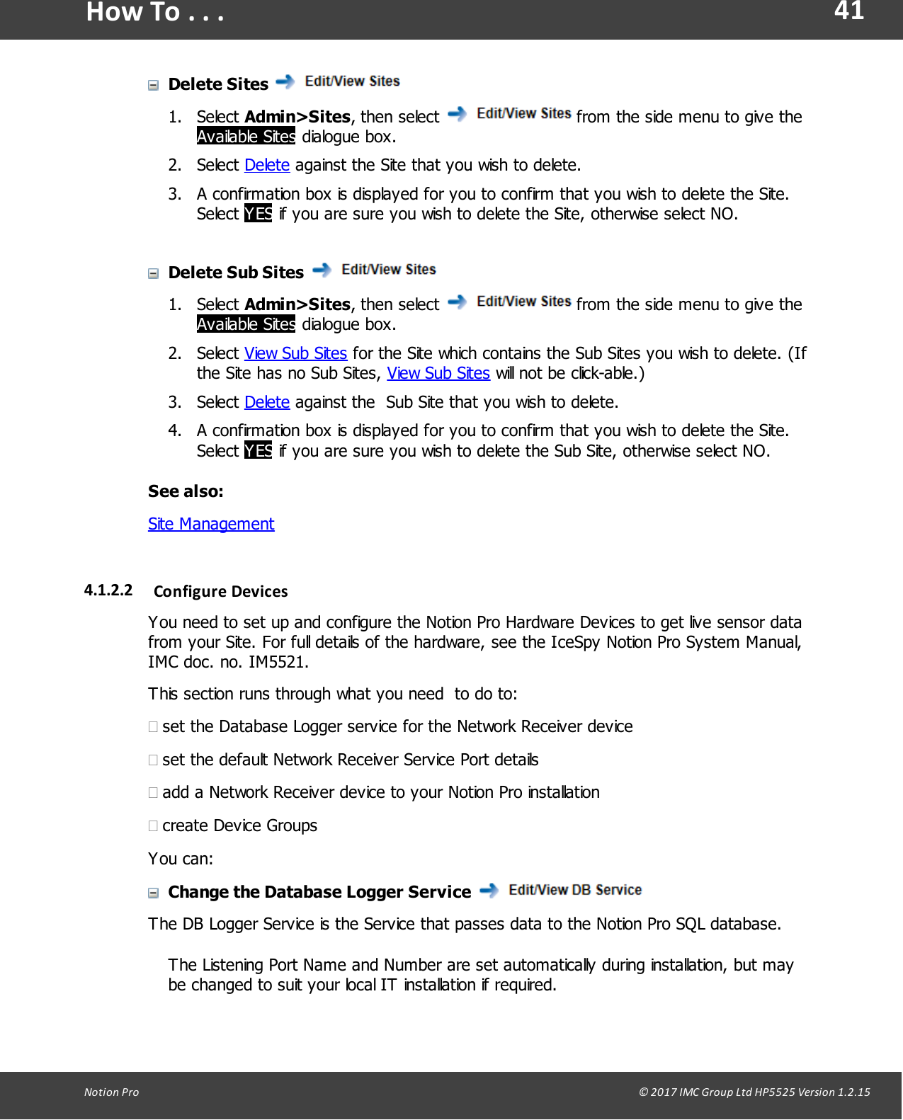
Ellab Monitoring Solutions IN-RP002F2 Notion Pro Echo Repeater User Manual Notion Pro
The IMC Group Ltd Notion Pro Echo Repeater Notion Pro
UserManual.wiki
>
Ellab Monitoring Solutions
>
IN RP002F2 User Manual
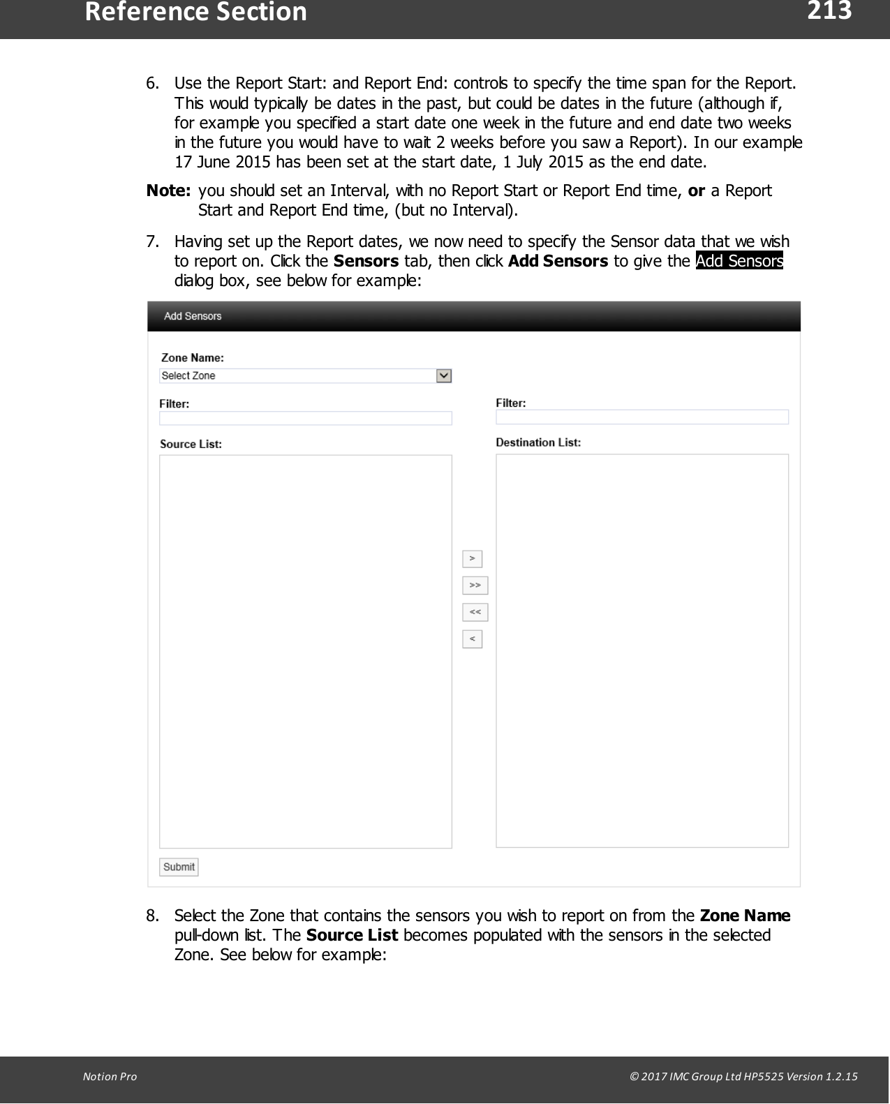
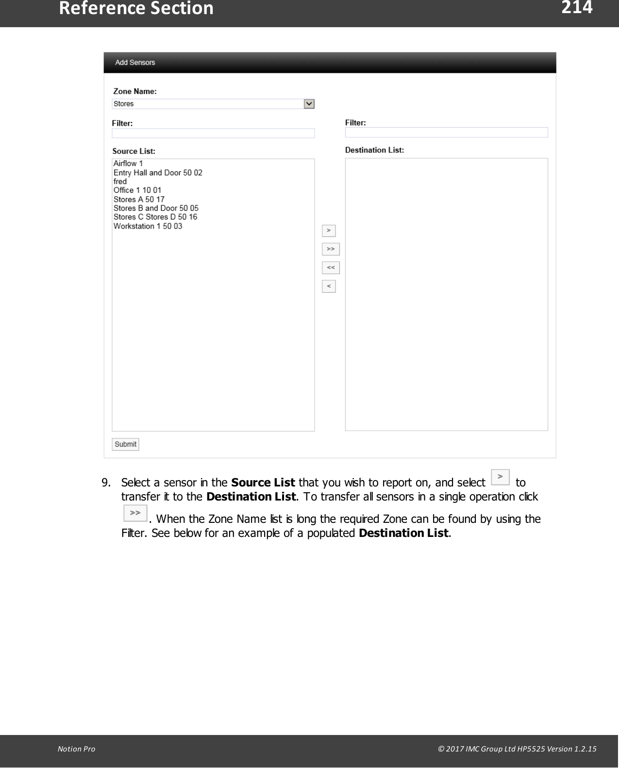
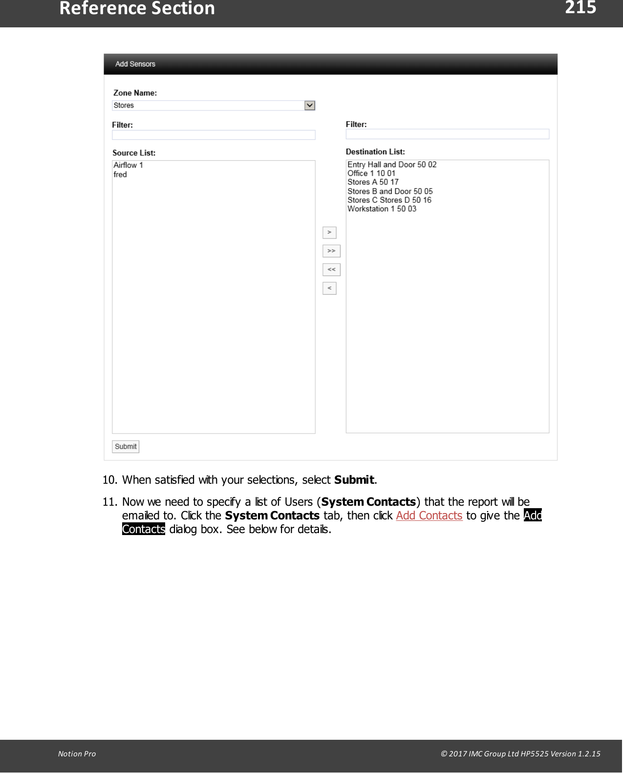
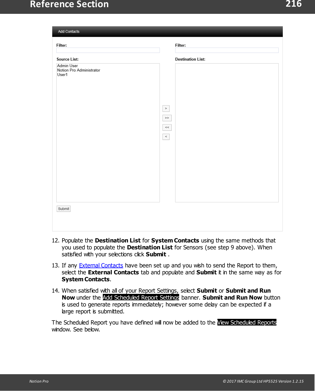
Users manual
Navigation menu
Upload a User Manual
Namespaces
Wiki Guide
HTML
PDF
Info
Views
User Manual
Discussion / Help
Navigation


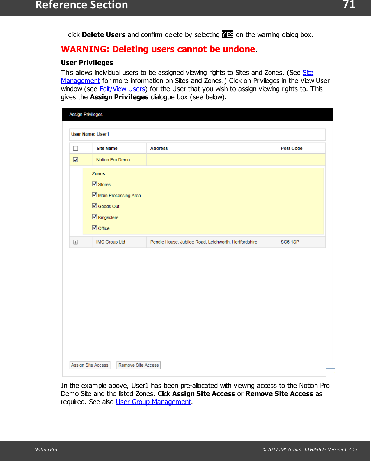
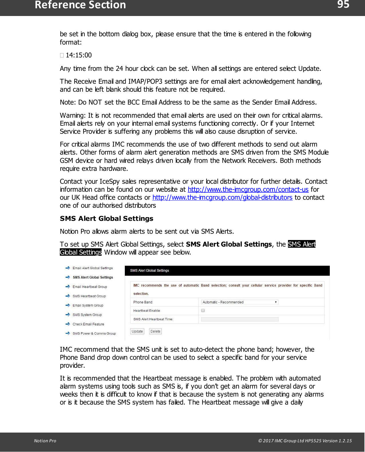
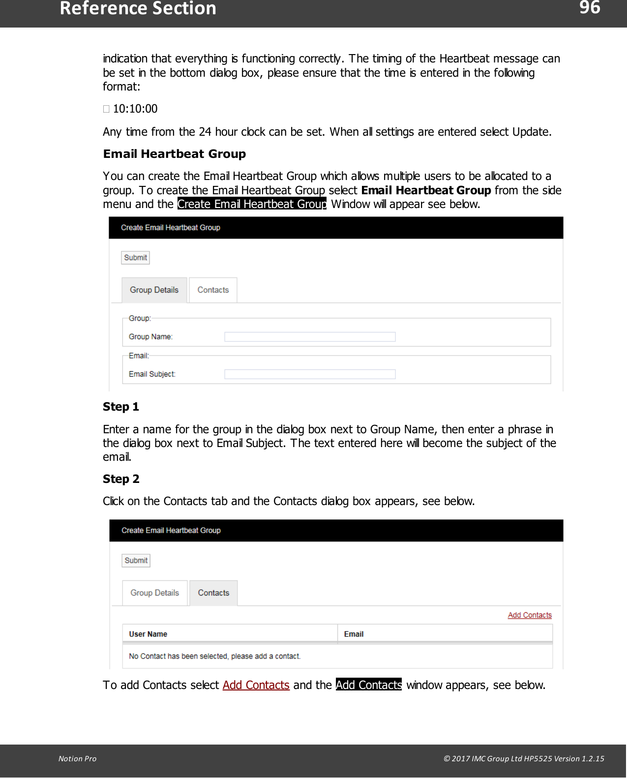
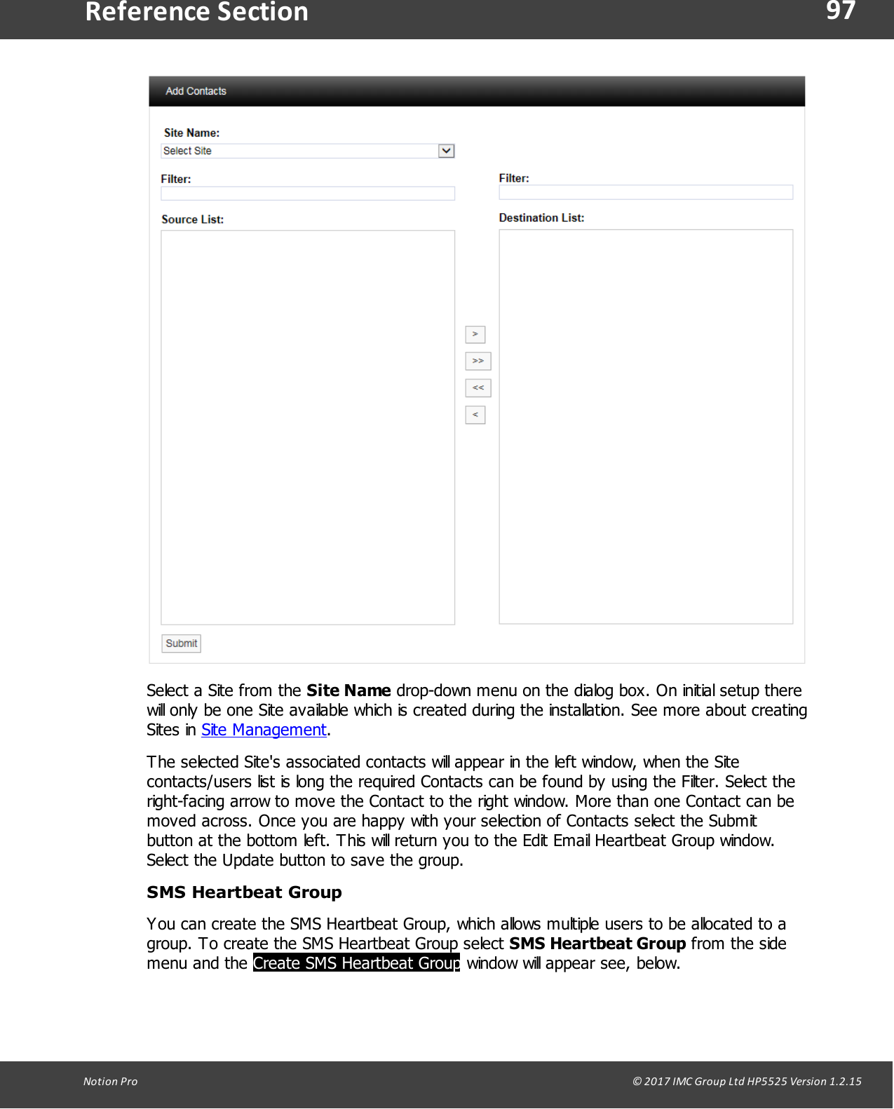
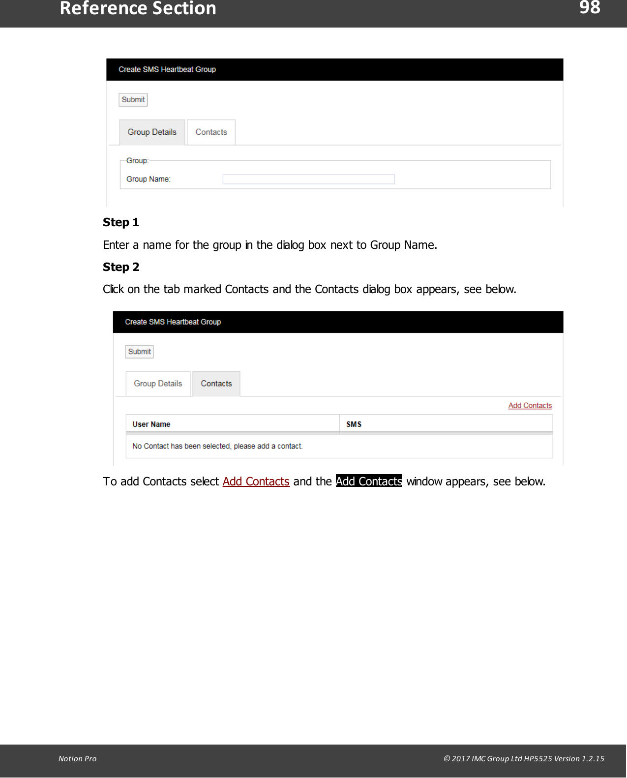
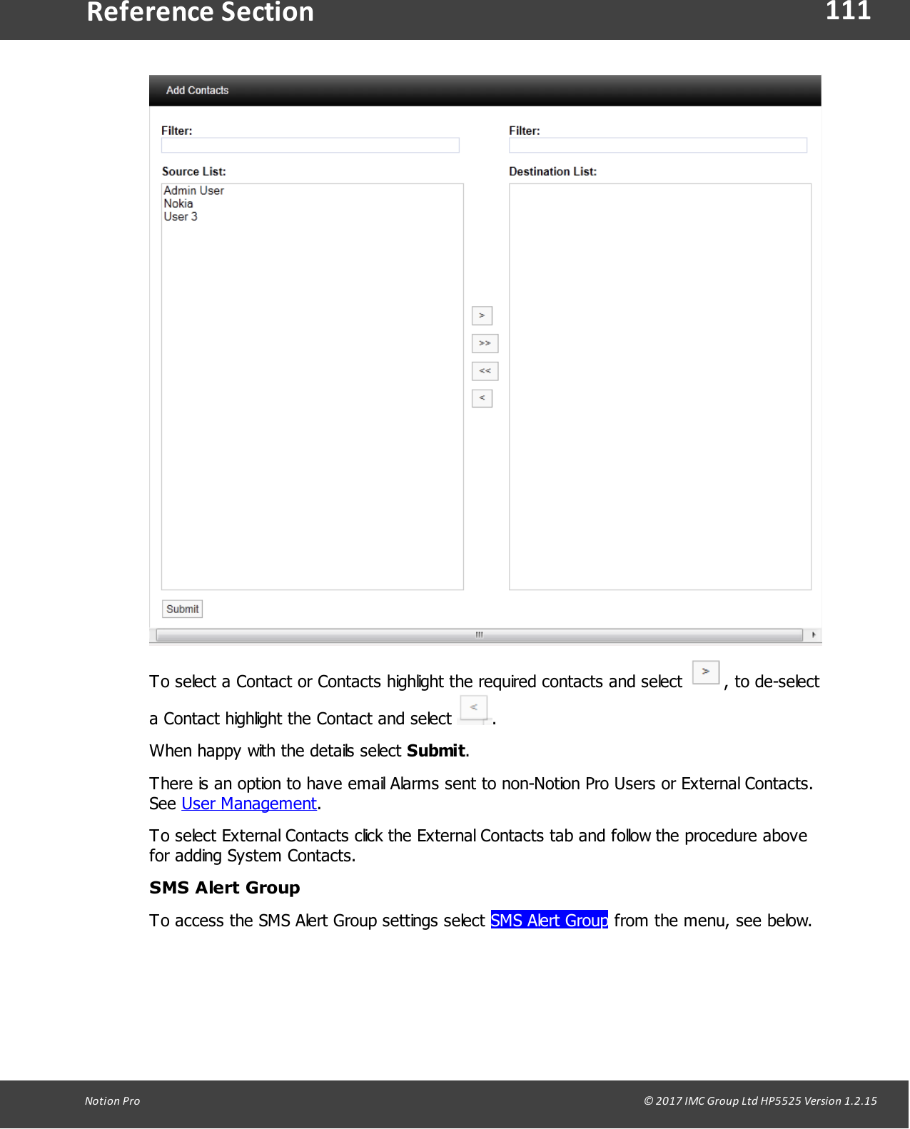
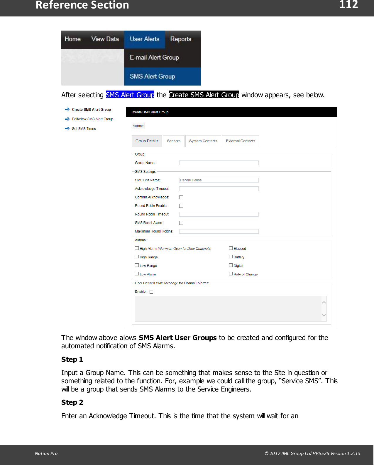

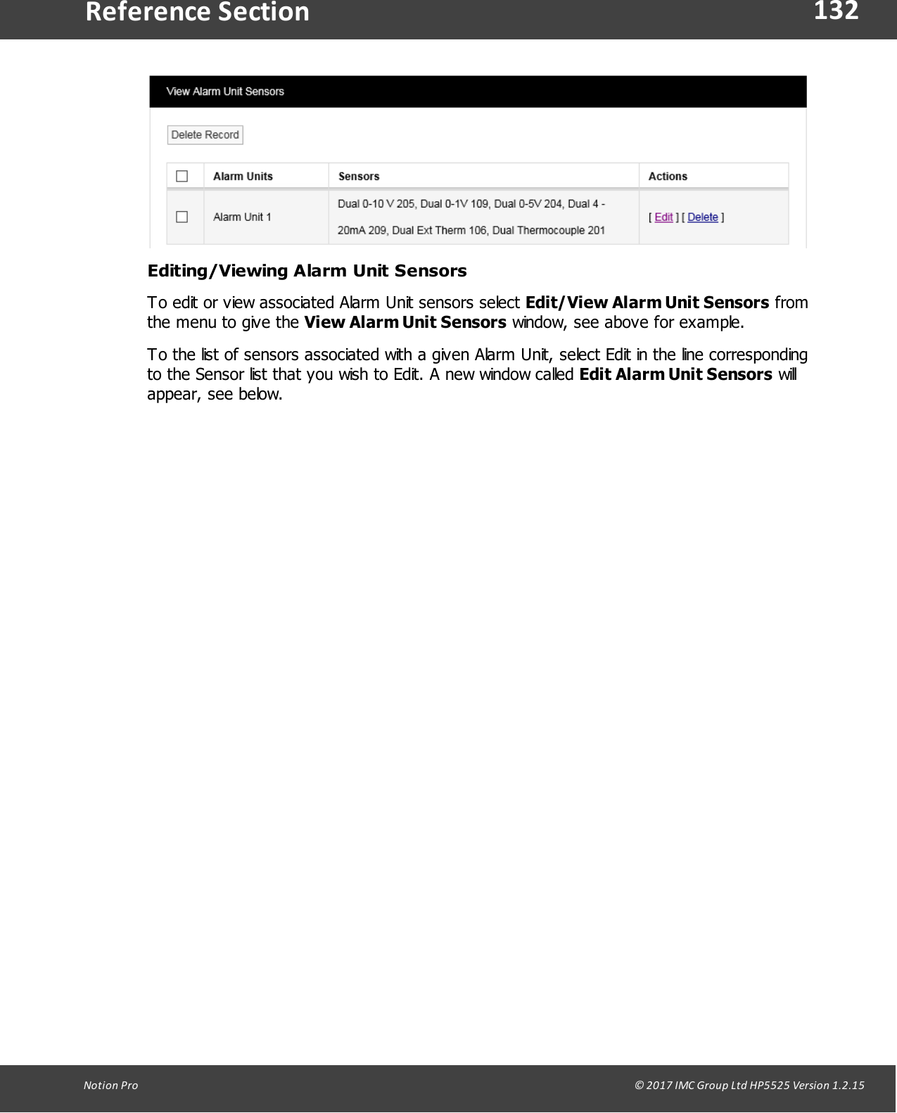
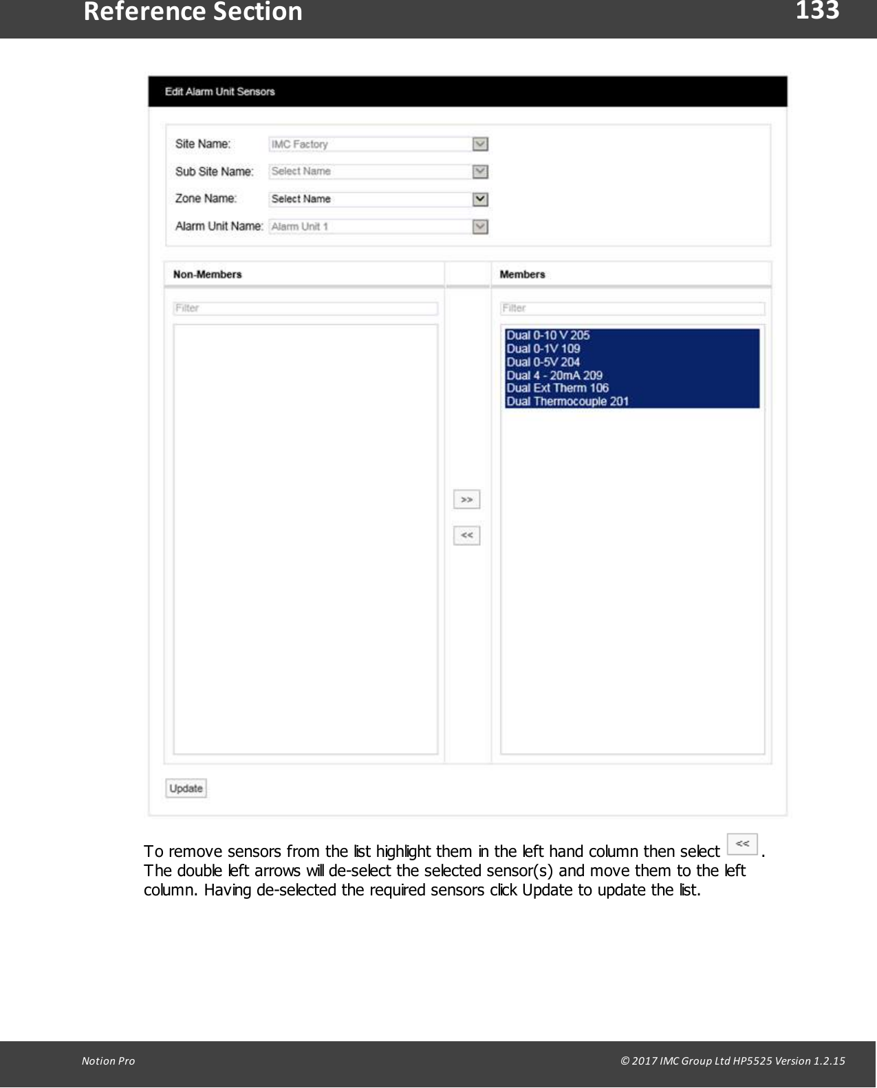

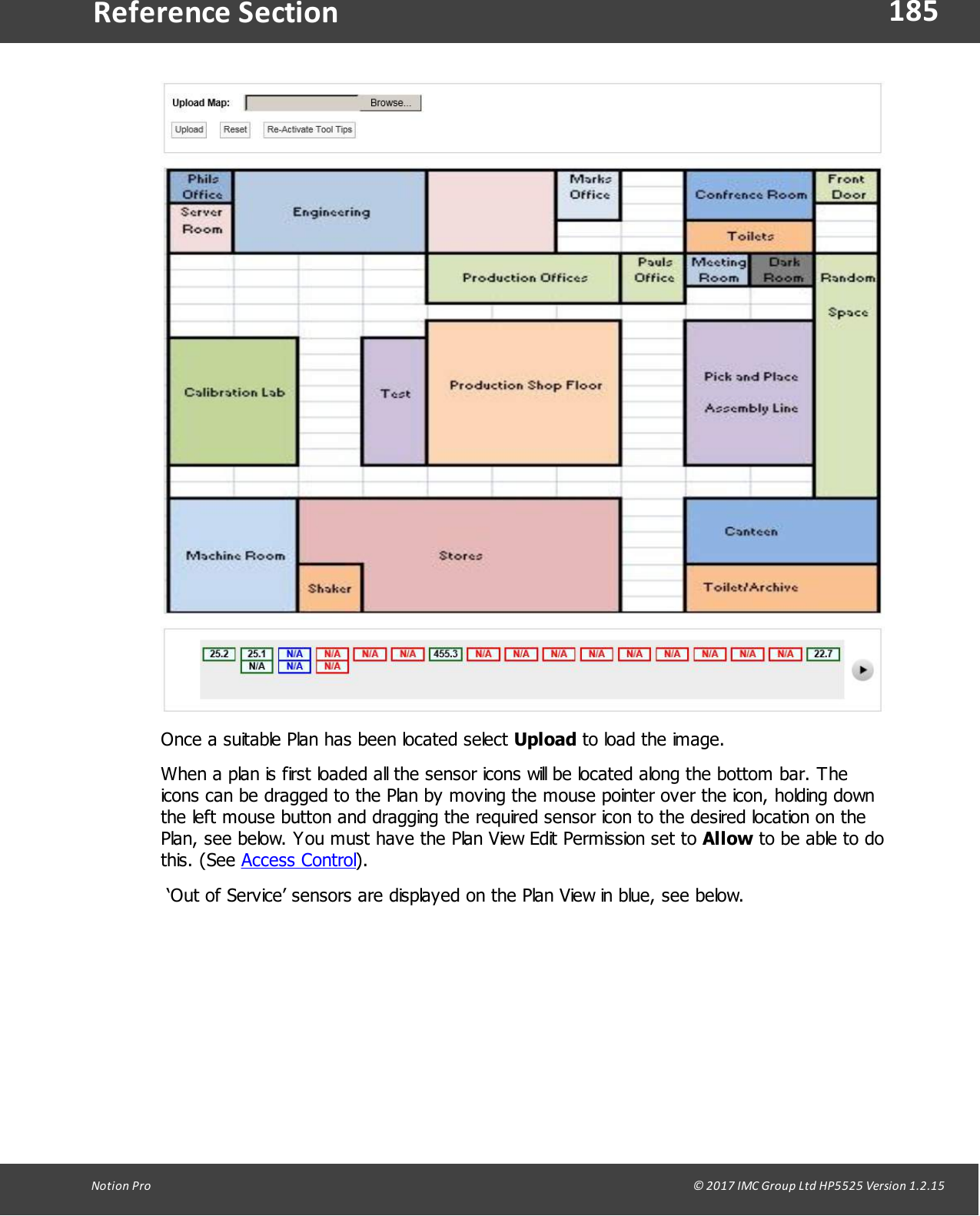
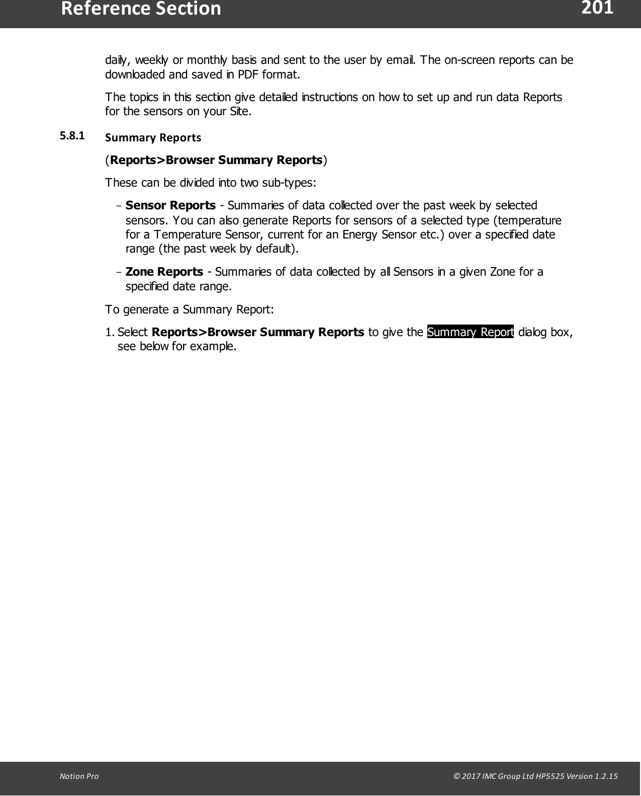
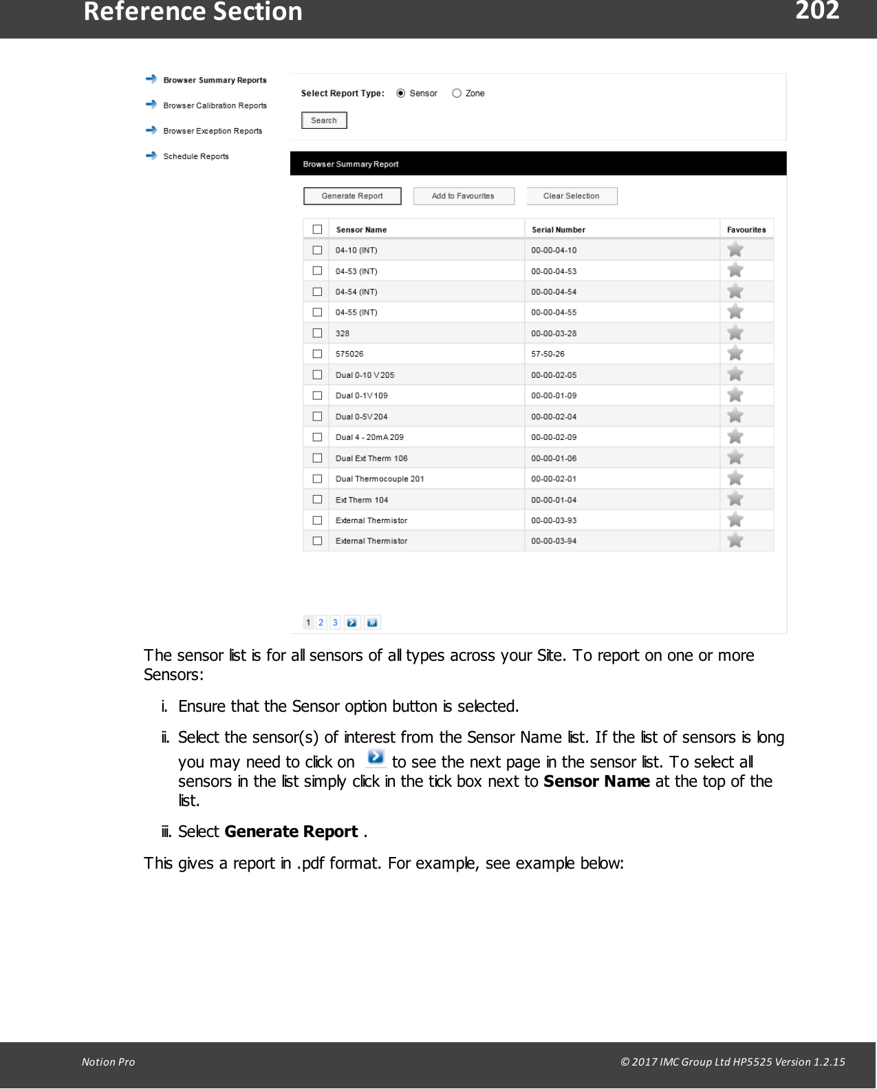
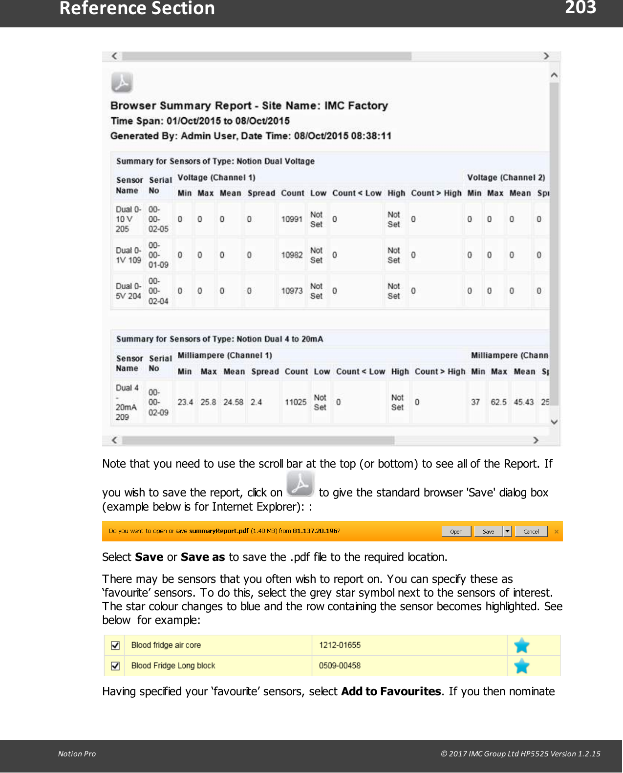
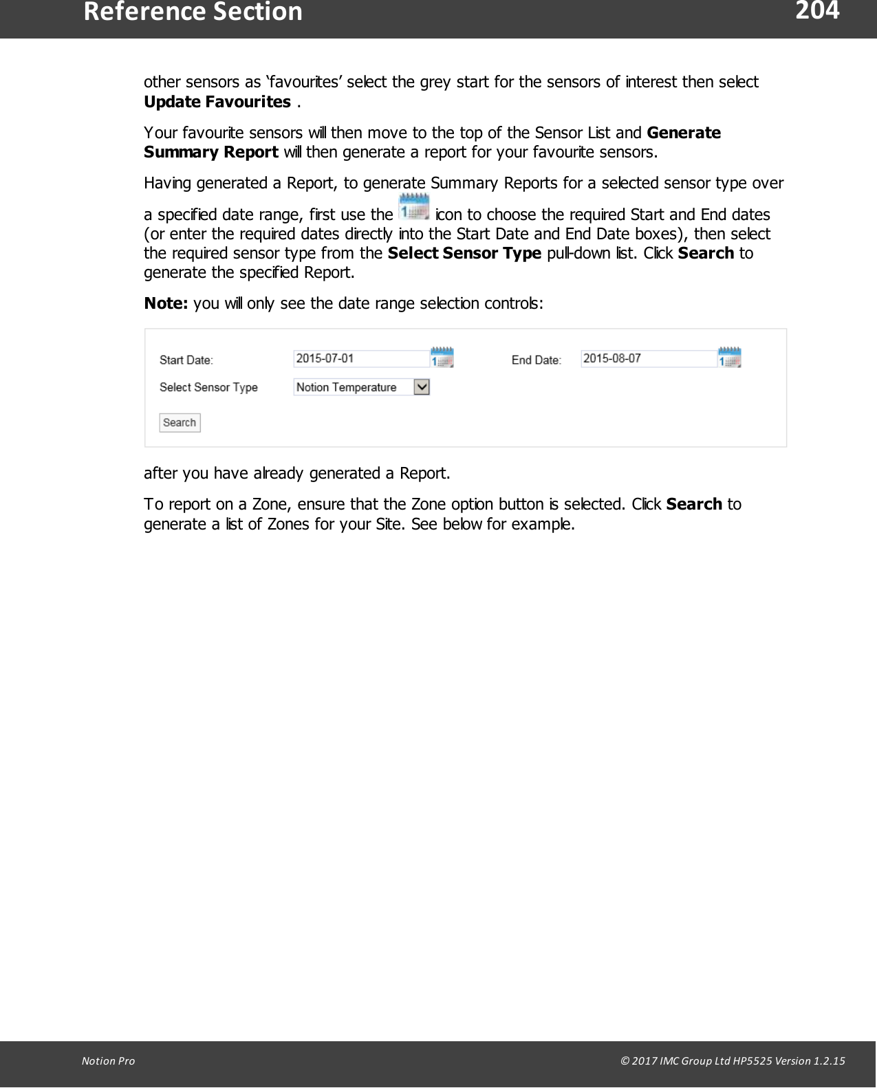
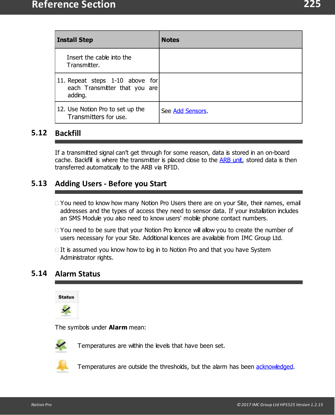
![160Notion Pro © 2017 IMC Group Ltd HP5525 Version 1.2.15Reference SectionClick on the Device Type combo control, and select the required control device type –Notion Base [Receiver Unit], IMC Alarm Unit or IMC SMS Unit, see below, then click on theDevice Name combo control and select the require device by name. The view will now change to display device information and Local Alarm options, see belowfor example.To use the Relay output, select the Relay Output option button. If you wish to use an output on a MS1000 card; select the option button adjacent to the](https://usermanual.wiki/Ellab-Monitoring-Solutions/IN-RP002F2/User-Guide-3408501-Page-160.png)

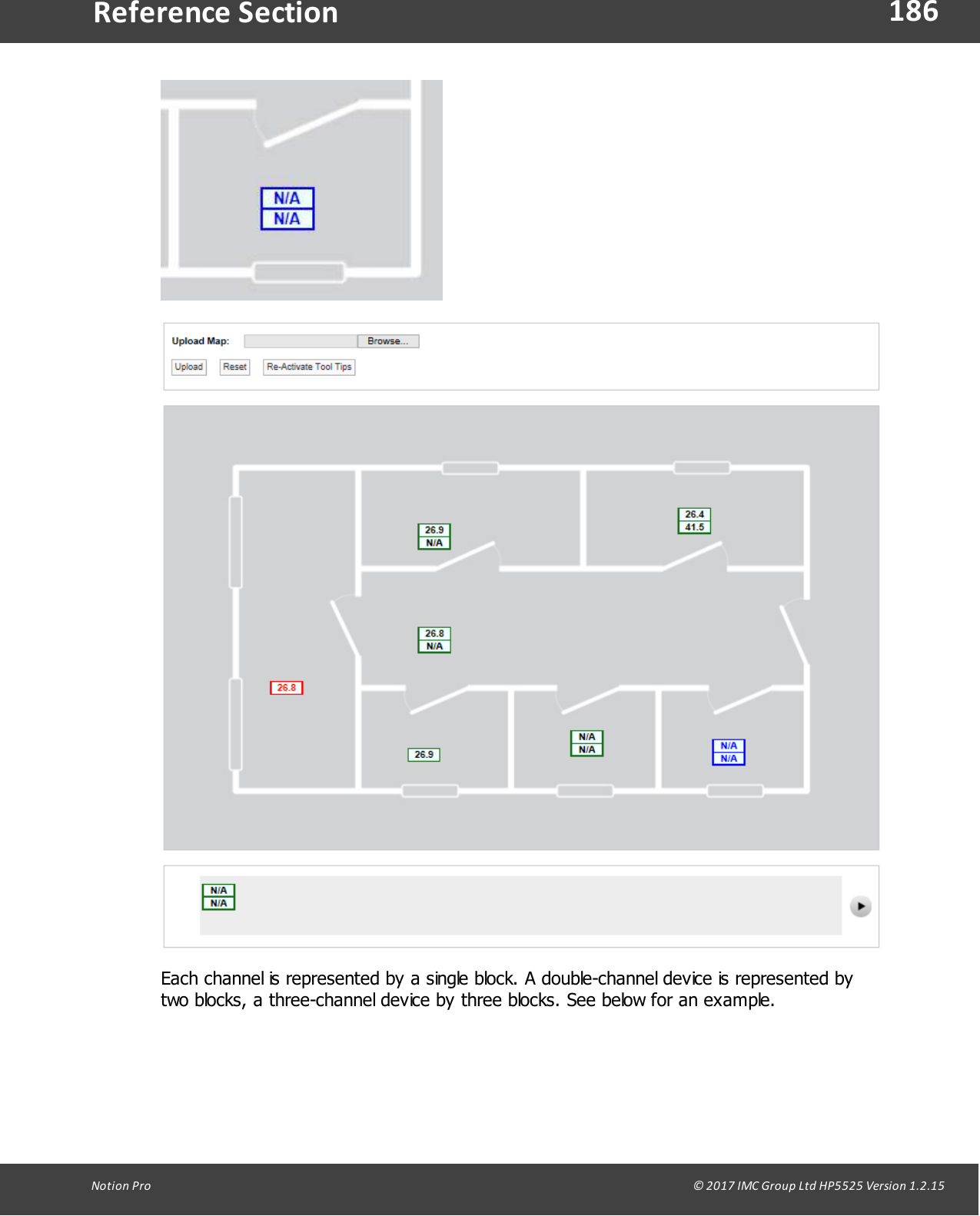
![180Notion Pro © 2017 IMC Group Ltd HP5525 Version 1.2.15Reference SectionFixed Scale (0-100)Each Sensor installs with a Default Scale which would cover the maximum range for thatSensor. This is Scale setting is OK if the Sensor is going to be used over its range. If it’s tobe used over a smaller range then a User Defined Scale may be more appropriate, seeabove.Auto ScaleThis feature allows the graph Scale to be set automatically. Auto Scale will set the graphScale to a very tight range which covers the range for the data displayed. This gives amuch expanded view of the data and may be confusing as the data can look like it ischanging dramatically.Select the Scale type you require by clicking the option button next to the Scale Type andselect Submit. The graph will re-draw with the new Scale settings, see below.The User Defined Scale for this Sensor is -40°C to +40°C and 0% to 100% RelativeHumidity. Using Auto Scale has rescaled the graph to 150°C to 23°C and -165%[theoretical] to 20% Relative Humidity.Export DataThe data associated with Day and Week interval graphs can be saved as a commaseparated variables file, (.CSV). The entire Day or Week’s data will be exported, irrespectiveof the current zoom state when the data is exported. To export data click Export Data.Once clicked you may be asked to choose between saving the file and opening with yourcomputer’s default spreadsheet application (see below). However, the exact action willdepend on the browser you are using, the default settings for your browser and thecomputer operating system and its setup. If you require assistance with this contact yoursystem administrator or IT support provider, please do NOT contact IMC TechnicalSupport, as this is help that only your administrator/support provider can supply.](https://usermanual.wiki/Ellab-Monitoring-Solutions/IN-RP002F2/User-Guide-3408501-Page-180.png)