Ellab Monitoring Solutions IN-RP002F2 Notion Pro Echo Repeater User Manual Notion Pro
The IMC Group Ltd Notion Pro Echo Repeater Notion Pro
Users manual

®
Notion Pro
USER MANUAL
© 2017 IMC Group Ltd HP5525 Version 1.2.15
IMC Group Ltd

2
Notion Pro © 2017 IMC Group Ltd HP5525 Version 1.2.15
Table of Contents
1. About Notion Pro Help 6
2. Introducing the Notion Pro System 7
2.1 What does Notion Pro do? ................................................................................................ 8
2.2 Installing your Notion Pro Equipment .............................................................................. 9
Notion Base Wall Bracket Extender ............................................................................ 132.2.1
3. Getting Started with the Notion Pro 15
3.1 The Opening Display ......................................................................................................... 16
The System Overview Page ......................................................................................... 173.1.1
Basic Operations in Notion Pro ................................................................................... 173.1.2
4. How To . . . 20
4.1 (Administrators) ................................................................................................................ 21
Set Up Users, Sites and Zones .................................................................................... 214.1.1
Create and Edit Users ................................................................................................................................... 214.1.1.1
Change a User's Password .......................................................................................................................... 234.1.1.2
Set Password Security .................................................................................................................................. 234.1.1.3
Create External Contacts ............................................................................................................................. 244.1.1.4
Create and Populate User Groups ............................................................................................................. 254.1.1.5
Create Sites and Subsites ............................................................................................................................ 264.1.1.6
Set Access Rights ........................................................................................................................................... 274.1.1.7
Create Zones ................................................................................................................................................... 294.1.1.8
Define Roles and Permissions .................................................................................................................... 304.1.1.9
Specify email and SMS Alert Settings ........................................................................................................ 334.1.1.10
Create Alert Groups ...................................................................................................................................... 384.1.1.11
Set Up Sensors ............................................................................................................. 394.1.2
Create, Edit and View Sites .......................................................................................................................... 394.1.2.1
Configure Devices ......................................................................................................................................... 414.1.2.2
Add Sensors .................................................................................................................................................... 434.1.2.3
Create and Edit Sensor Groups ................................................................................................................... 464.1.2.4
4.2 (All Users) ........................................................................................................................... 47
Get a Quick View of ... ................................................................................................ 484.2.1
sensor readings ............................................................................................................................................. 484.2.1.1
alarm statuses ............................................................................................................................................... 494.2.1.2
a sensor reading in graphical form .......................................................................................................... 514.2.1.3
Look at Sensor readings from . . . ................................................................................ 534.2.2
another Zone .................................................................................................................................................. 534.2.2.1
another Day .................................................................................................................................................... 544.2.2.2
another time interval ................................................................................................................................... 554.2.2.3
View and Acknowledge Alarms ................................................................................... 564.2.3
View System Alarm Status Overview ......................................................................................................... 564.2.3.1
View System Messages ................................................................................................................................. 574.2.3.2

3
Notion Pro © 2017 IMC Group Ltd HP5525 Version 1.2.15
Table of Contents
Acknowledge Alarms .................................................................................................................................... 574.2.3.3
4.3 Create and View Reports .................................................................................................. 58
4.4 View System Logs .............................................................................................................. 61
5. Reference Section 63
5.1 Signing In ........................................................................................................................... 64
View Archived Databas e ............................................................................................. 655.1.1
View Live Database ..................................................................................................... 665.1.2
5.2 Setting Up Users, Sites and Devices ................................................................................. 66
Us er Ma na g ement ....................................................................................................... 665.2.1
User Group Management ............................................................................................ 775.2.2
Access Control ............................................................................................................. 825.2.3
Sys tem C onfi g uration .................................................................................................. 935.2.4
Us er Alerts ................................................................................................................. 1065.2.5
Site Ma nag ement ...................................................................................................... 1175.2.6
Devic e Config ura ti on ................................................................................................. 1215.2.7
5.3 Setting Up Sensors .......................................................................................................... 134
Addi ng Z ones ............................................................................................................. 1355.3.1
Editing Zones ............................................................................................................................................... 1375.3.1.1
Deleting Zones ............................................................................................................................................. 1385.3.1.2
Addi ng Sensors .......................................................................................................... 1385.3.2
C onfi g uring Sensors .................................................................................................. 1425.3.3
Setting Ala rms ........................................................................................................... 1465.3.4
5.4 Setting Up Sensor Groups .............................................................................................. 157
Creating Sens or Groups ............................................................................................. 1585.4.1
Loca l Ala rms .............................................................................................................. 1595.4.2
Viewing Sens or Groups ............................................................................................. 1615.4.3
5.5 Viewing Data .................................................................................................................... 162
Signi ng In ................................................................................................................... 1625.5.1
Viewing the Live Database ....................................................................................... 1665.5.2
Choosing the Site to View ......................................................................................... 1665.5.3
Operations from the Live View ................................................................................. 1675.5.4
The Plan View ............................................................................................................ 1845.5.5
The Default View ....................................................................................................... 1885.5.6
Globa l Settings .......................................................................................................... 1895.5.7
Globa l Uni ts ............................................................................................................... 1905.5.8
Dec i mal Pla c es .......................................................................................................... 1915.5.9
5.6 Viewing Live Data ............................................................................................................ 192
5.7 Alarm Management ........................................................................................................ 195
System Status Overview ............................................................................................ 1955.7.1

4
Notion Pro © 2017 IMC Group Ltd HP5525 Version 1.2.15
Table of Contents
Acknowledgi ng Ala rms .............................................................................................. 1975.7.2
5.8 Setting Up and Running Reports ................................................................................... 200
Summa ry Re ports ...................................................................................................... 2015.8.1
C a li bration R eports ................................................................................................... 2055.8.2
Exc epti on Reports ..................................................................................................... 2075.8.3
Scheduled Reports ..................................................................................................... 2115.8.4
Re ports Fol der ........................................................................................................... 2175.8.5
5.9 Viewing System Logs ....................................................................................................... 217
Acti vity Logs .............................................................................................................. 2185.9.1
Ala rm L og s ................................................................................................................. 2205.9.2
SMS L ogs ................................................................................................................... 2215.9.3
Ema i l L og s ................................................................................................................. 2215.9.4
5.10 Settings ............................................................................................................................ 222
5.11 Adding Transmitters ....................................................................................................... 223
5.12 Backfill .............................................................................................................................. 225
5.13 Adding Users - Before you Start .................................................................................... 225
5.14 Alarm Status .................................................................................................................... 225
5.15 Battery ............................................................................................................................. 226
5.16 Door Alarm ...................................................................................................................... 226
5.17 Equipment Positioning ................................................................................................... 227
5.18 Live Data .......................................................................................................................... 227
5.19 Manuals ............................................................................................................................ 228
5.20 Permissions ...................................................................................................................... 228
5.21 Receiver Connectors ....................................................................................................... 228
5.22 Receiver Lights ................................................................................................................. 229
5.23 Roles ................................................................................................................................. 229
5.24 Specifying Alert Settings - Before you Start ................................................................. 230
5.25 User Groups ..................................................................................................................... 231
5.26 User Privileges ................................................................................................................. 231
5.27 Compliance ...................................................................................................................... 231
5.28 Terms and Conditions of Sale ......................................................................................... 232
6. The Notion Pro Hardware 236
6.1 The Network Receiver .................................................................................................... 237
LEDs ........................................................................................................................... 2386.1.1
Connectors ................................................................................................................ 2396.1.2
6.2 The Echo Module ............................................................................................................ 239

5
Notion Pro © 2017 IMC Group Ltd HP5525 Version 1.2.15
Table of Contents
Connectors ................................................................................................................ 2406.2.1
6.3 The SMS Module ............................................................................................................. 241
Ins tallation and Operation ........................................................................................ 2426.3.1
Connectors ................................................................................................................ 2446.3.2
6.4 The ARB Module .............................................................................................................. 245
Connectors ................................................................................................................ 2466.4.1
6.5 The Calibration Module .................................................................................................. 246
Connectors ................................................................................................................ 2476.5.1
Display ....................................................................................................................... 2476.5.2
Operation .................................................................................................................. 2476.5.3
6.6 The Transmitters ............................................................................................................. 248
Single Channel, Air Temperature, Internal ................................................................ 2496.6.1
Single Channel, Air Temperature, Internal + Door Switch ......................................... 2506.6.2
Single Channel, External Temperature Probe ........................................................... 2506.6.3
Single Channel, External Temperature Probe + Door Switch .................................... 2516.6.4
Dual Channel Internal/External Temperature Probe ................................................. 2516.6.5
Dual Channel External Thermistor ............................................................................ 2526.6.6
Single Channel, External PT100 Probe ...................................................................... 2526.6.7
Single Channel PT100 Probe + Door Switch .............................................................. 2536.6.8
Dual Channel PT100 Probe ........................................................................................ 2536.6.9
Single Channel Type T Thermocouple ....................................................................... 2536.6.10
Dual Channel Type T Thermocouple ......................................................................... 2546.6.11
Single Channel Type T Thermocouple + Door Switch ................................................ 2546.6.12
Dual Channel 4-20mA Input ...................................................................................... 2556.6.13
Dual Channel Voltage Input Transmitter .................................................................. 2556.6.14
Temperature and RH Transmitter ............................................................................. 2556.6.15
Linear Transmitter (1V 5V 10V 4 to 20mA) ............................................................... 2566.6.16
6.7 Base Unit Installation Procedure (typical) .................................................................... 257
6.8 Relay Connections ........................................................................................................... 259
7. Using the Help 260
8. Frequently Asked Questions 263
9. Warnings FCC 280
Index 281

6
Notion Pro © 2017 IMC Group Ltd HP5525 Version 1.2.15
About Notion Pro Help
1About Notion Pro Help
Welcome to the Notion Pro online help system.
The current release of Help is version 1.2.15, release date 19th January 2017

Introducing the Notion Pro System

8
Notion Pro © 2017 IMC Group Ltd HP5525 Version 1.2.15
Introducing the Notion Pro System
2Introducing the Notion Pro System
2.1 What does Notion Pro do?
IceSpy Notion Pro enables you to configure and monitor temperature sensors installed in
(typically) refrigerated storage units or other temperature-sensitive environments.
Notion Pro is a System, containing software and hardware. For details of the hardware, see
The Notion Pro Hardware, also http://www.the-imcgroup.com/notionpro/.
The Notion Pro software (described in this Help) gives a graphical user interface (GUI) which
works through all the main web browsers, for display on a desktop PC, laptop or mobile
device such as a tablet or smart phone.
Summary of Functionality
Data is mainly generated by wireless sensors and collected by wireless receivers. The data
is relayed to the server by TCP/IP, USB or GPRS and is stored in an SQL database. The
data is then available for viewing using a local management application or via a standard
Web Browser.
Notion Pro is:
Scalable
Notion Pro can be installed on a single site with 1 user up to 100’s of sites with
1000’s of users.
Browser-
based
Notion Pro uses commercially available browsers such as Internet Explorer,
Chrome or Firefox to view the data.
SQL
Database
Notion Pro uses an SQL database - the modern method making it easy to
access data. The SQL database could be used by 3rd-party tools if required/
commercially desirable.
Notion Pro:
·allows you to rapidly change what you need to, given the necessary permissions
·allows you to select any combination(s) of sensors to form ‘Views’ with all subsequent
operations (alarms, reporting) only operating on that subset
·gives you control of exception handling protocols, the various options do not have to be
generically configured by the Administrator
·has extensive reporting capabilities, with custom reports available as easily accessible plug-
ins to the main system (future proofing/ready customisation)
·has a totally separate GUI (Graphical User Interface) from the underlying hardware
·is a services-based system
·architecture ensures that support for as yet unknown hardware can be readily integrated
9
Notion Pro © 2017 IMC Group Ltd HP5525 Version 1.2.15
Introducing the Notion Pro System
(future proofing) by modularising the hardware services and accessing the database via a
universal interface module
·uses Browser technology as the primary view (optionally over the web BUT NOT
NECESSARILY, could be all Intranet). Browser support will likely be there as long as
computers run, the risk of problems caused by Operating System Providers is therefore
minimised
·allows seamless support for large numbers of sensor communication protocols, and very
large numbers of sensors over multiple sites.
See Also
Getting Started with Notion Pro
2.2 Installing your Notion Pro Equipment
A typical Notion Pro installation would consist of one or more Network Receivers (sometimes
referred to as a Base Station) and a number of sensors (transmitters). For the
transmitters, the procedure below (starting at Step 10) would need to be followed for each
transmitter that you are using.
The procedure below is for installing the Network Receiver. The procedures for installing the
Notion Pro family of Base Units (i.e. the Network Receiver, the Echo Module, the SMS
Module and the ARB Module) are very similar. For details of the hardware, see the IceSpy
Notion Pro System Manual, IMC doc. no. IM5521.
As far as possible, the Receiver and Transmitter units should be placed where they will not
be subject to electromagnetic interference and where they will not be shielded by walls,
doors, furniture, appliances etc. See Equipment Positioning for more details.
Install Step
Notes
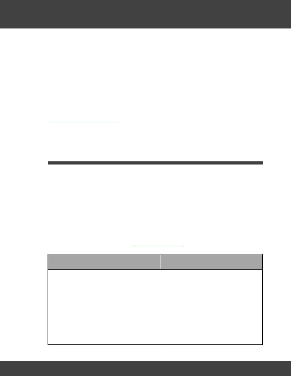
1. Using the mounting bracket as a drilling
template, drill holes for the receiver wall
mounting bracket into the wall at an
appropriate location.
2. Using the spacers provided to give
clearance, screw the mounting bracket to
the wall.
When mounting the Receiver, you should
bear in mind that you will need to run
cables from the Receiver to the mains
power supply and to your network socket.
10
Notion Pro © 2017 IMC Group Ltd HP5525 Version 1.2.15
Introducing the Notion Pro System
Install Step
Notes
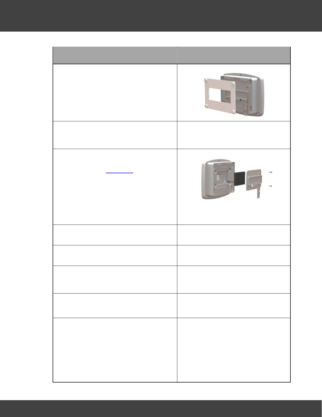
3. Using a Phillips screwdriver, remove and
retain the screws from the battery cover
plate at the rear of the Receiver.
4. Note: If installing an SMS Module, the
SIM card must be installed prior to battery
installation, see Installation.
Insert the 8.4V backup battery into the
recess at the rear of the Receiver, taking
care to insert the connector attached to
the battery into the matching connector
within the Receiver.
5. Screw the battery cover plate to the rear
of the Receiver.
6. Attach the Receiver to the mounting
bracket.
7. Using the supplied Ethernet cable, connect
the Receiver to your Network connection if
you have one.
8. Using the supplied cable, connect the
Receiver to the mains power supply.
9. If you are NOT using the door monitoring
and alarm function option with this
transmitter, go to step 11 below.
Secure a matching pair of door monitoring
and alarm function sensor pads to the
door and door frame of your refrigerated/
frozen storage unit.
If you intend to the lay the transmitter
loosely in the storage unit, ensure that
you position the door frame sensor pad
such that the cable running from the pad
goes into the storage unit.
If you intend to wall-mount the
transmitter, ensure that you position the
11
Notion Pro © 2017 IMC Group Ltd HP5525 Version 1.2.15
Introducing the Notion Pro System
Install Step
Notes
door frame sensor pad such that the
cable running from the pad runs outside of
the storage unit.
Ensure that the pads meet perfectly when
the door is closed.
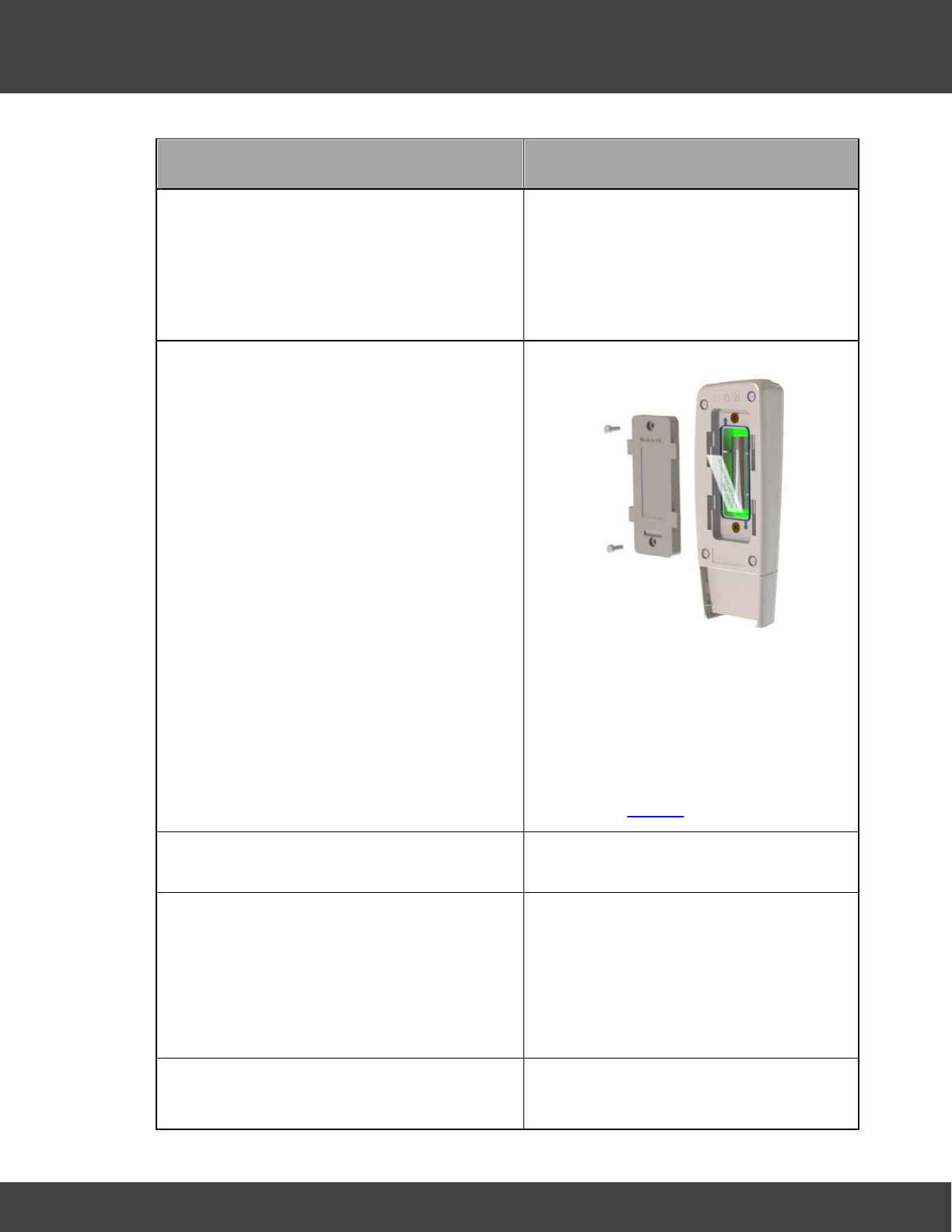
10. Pull away the contact tag on the
transmitter to ensure the battery contacts
and the transmitter contacts meet.
A green light will flash briefly.
The transmitters are powered by 1 x 1.5V
Lithium AA cells. Standard AA cells can be
used, but are not recommended. (1.5V
Lithium AA batteries supplied with
transmitter will work over range -30°C to
+50°C. 1.5V AA alkaline can be used but
will have reduced life and a reduced
operating temperature range 0°C to +40°
C.) See also Battery.
11. If you do NOT intend to wall-mount your
transmitter, go to step 20 below.
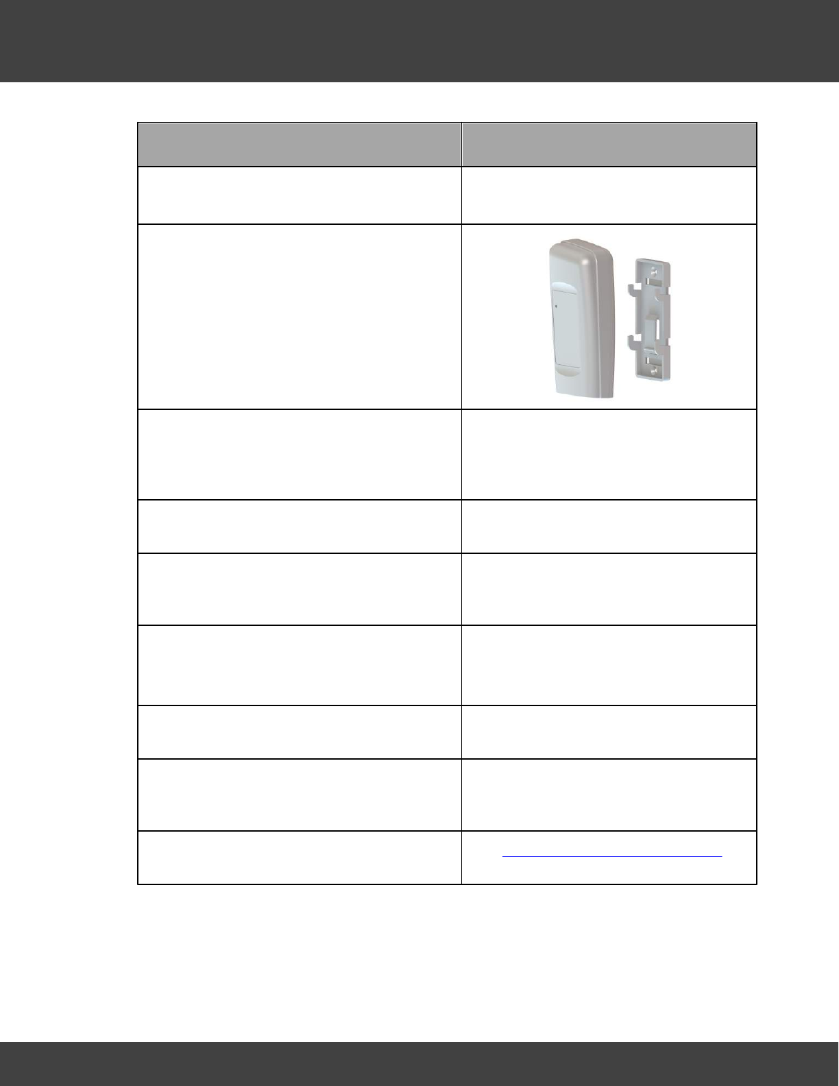
12. Drill holes for the transmitter wall mounting
bracket into the wall at an appropriate
location.
When mounting the transmitter bracket,
you should bear in mind that, if you are
using the door monitoring and alarm
function and/or external sensor options,
you will need to run cables from the
transmitter to your storage unit door
frame sensor pad and/or external sensor.
13. Screw the mounting bracket to the wall.
As an alternative, the transmitter bracket
could be attached to a suitable post using
12
Notion Pro © 2017 IMC Group Ltd HP5525 Version 1.2.15
Introducing the Notion Pro System
Install Step
Notes
cable ties. Slots are provided in the
bracket for this purpose.
14. Slot the transmitter onto the wall bracket.
15. If you are using the door monitoring and
alarm function option with this transmitter,
route the storage unit door frame sensor
pad cable up to the transmitter.
16. If you are NOT using the external sensor
option, go to step 20.
17. Place the external temperature probe and
associated cable at a suitable position in
your storage unit.
18. Route the temperature probe cable over
the door frame and up to the transmitter.
Insert the cable into the transmitter.
19. Repeat steps 10-19 above for each
transmitter that you are using.
20. Plug in the Receiver power supply to the
mains supply and switch on at the mains
socket.
The green power LED comes on.
21. Go into Notion Pro to add transmitters to
Zones and set them up for use.
See Setting Up the Sensor Model for
details.
13
Notion Pro © 2017 IMC Group Ltd HP5525 Version 1.2.15
Introducing the Notion Pro System
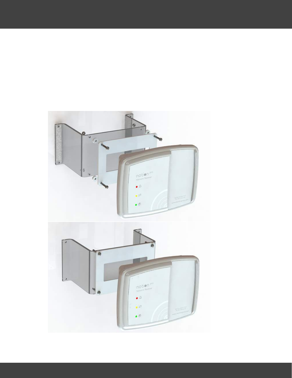
2.2.1 Notion Base Wall Bracket Extender
The Notion Base plastic Wall Bracket has been designed to provide a solution to the lack of
space between the Notion Base unit and the wall.
During some installations we have encountered radio reception interference caused by
certain materials within a wall such as metal.
This bracket helps bring the Notion Base away from the wall enough for the radio
transmission to work as specified.
Part Number: IN-WBE.

14
Notion Pro © 2017 IMC Group Ltd HP5525 Version 1.2.15
Introducing the Notion Pro System
Note:
All Extender holes are 4.5mm Diameter; fixings to attach Extender to users mounting
surface are not included.
The base mounting plate and spacers are supplied with the base, not with the extender
bracket.

Getting Started with the Notion Pro
16
Notion Pro © 2017 IMC Group Ltd HP5525 Version 1.2.15
Getting Started with the Notion Pro
3Getting Started with the Notion Pro
Administrator Users
After you have installed Notion Pro and physically installed your Base Units and Transmitters
you need to:
1. Set up the Notion Pro Users.
2. Create Sites, Subsites and Zones for your installation.
3. Add Base Units to your installation.
4. Add Sensors for use in your installation.
Standard Users
Look at the Help on the opening display which shows you around the Notion Pro user
interface, and gives you links to further Help about how to use Notion Pro to monitor your
temperature data.
3.1 The Opening Display
If there is only one Site in your Notion Pro installation, when you first enter Notion Pro you
will see something like:
Click on an area of the above display for help on that area.
If there is more than one Site in your installation you will see something like the picture
below, and you must choose the Site to view:
17
Notion Pro © 2017 IMC Group Ltd HP5525 Version 1.2.15
Getting Started with the Notion Pro
See Choosing the Site to View.
3.1.1 The System Overview Page
Click on an area of the above display for help on that area.
You see the System Overview when you have signed in to Notion Pro, selected the
Database and clicked .
Wherever you are in Notion Pro, you can go back to the Home Page simply by clicking on
.
See also . . .
The Opening Display
Basic Operations in Notion Pro
3.1.2 Basic Operations in Notion Pro
From the Menu Bars
The Menu Bars are where the System Administrator performs all the principal Setup and
Control operations within Notion Pro.
18
Notion Pro © 2017 IMC Group Ltd HP5525 Version 1.2.15
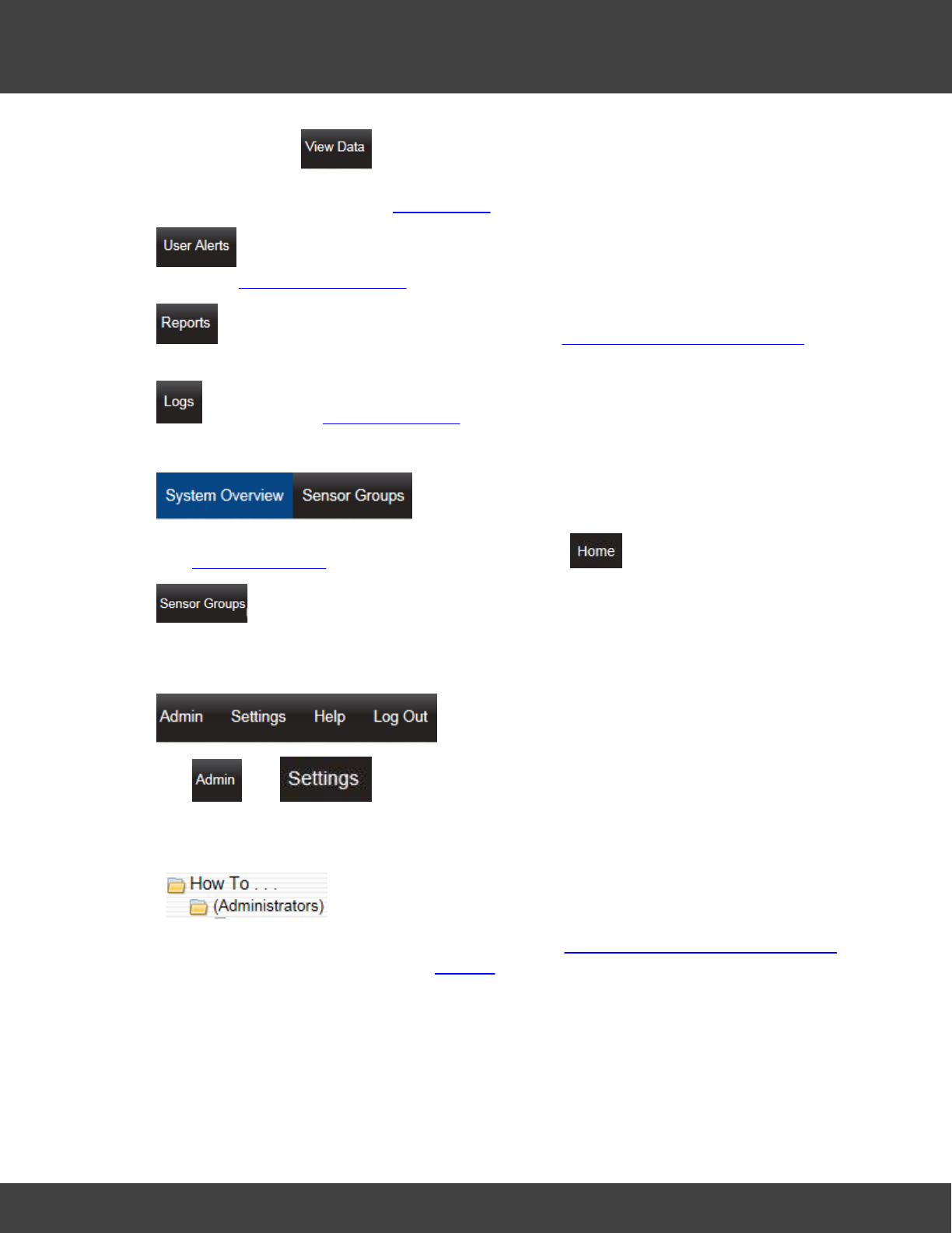
Getting Started with the Notion Pro
The options under enable you to view Live data (all Users) and set and
manipulate various aspects of data which go to make up the Live Data display (System
Administrator Users only). See Viewing Data for more details.
enables you to set up email and SMS User Alerts (System Administrator Users
only). See Setting Up User Alerts for more details.
enables you to set up and run Reports. See Setting Up and Running Reports for
more details.
enables you to view System Logs (all Users).
The System Overview page comes up when you click .
displays the available Sensor Groups which have been set up by the System
Administrator.
The and menus enable the System Administrator to set up Notion Pro
for use following installation.
See the
menu for Help on typical Notion Pro setup tasks, and Setting Up Users, Sites and Devices
for Reference Information. See also Settings.
From the Opening Display
For each transmitter you can:

How To . . .
21
Notion Pro © 2017 IMC Group Ltd HP5525 Version 1.2.15
How To . . .
4How To . . .
See the below for a list of things that you might want to do in Notion Pro.
4.1 (Administrators)
4.1.1 Set Up Users, Sites and Zones
4.1.1.1 Create and Edit Users
Read this first.
You need to create Users, give them Usernames and Passwords. You also need to assign
Access Rights, Privileges, Permissions and Roles to the Users.
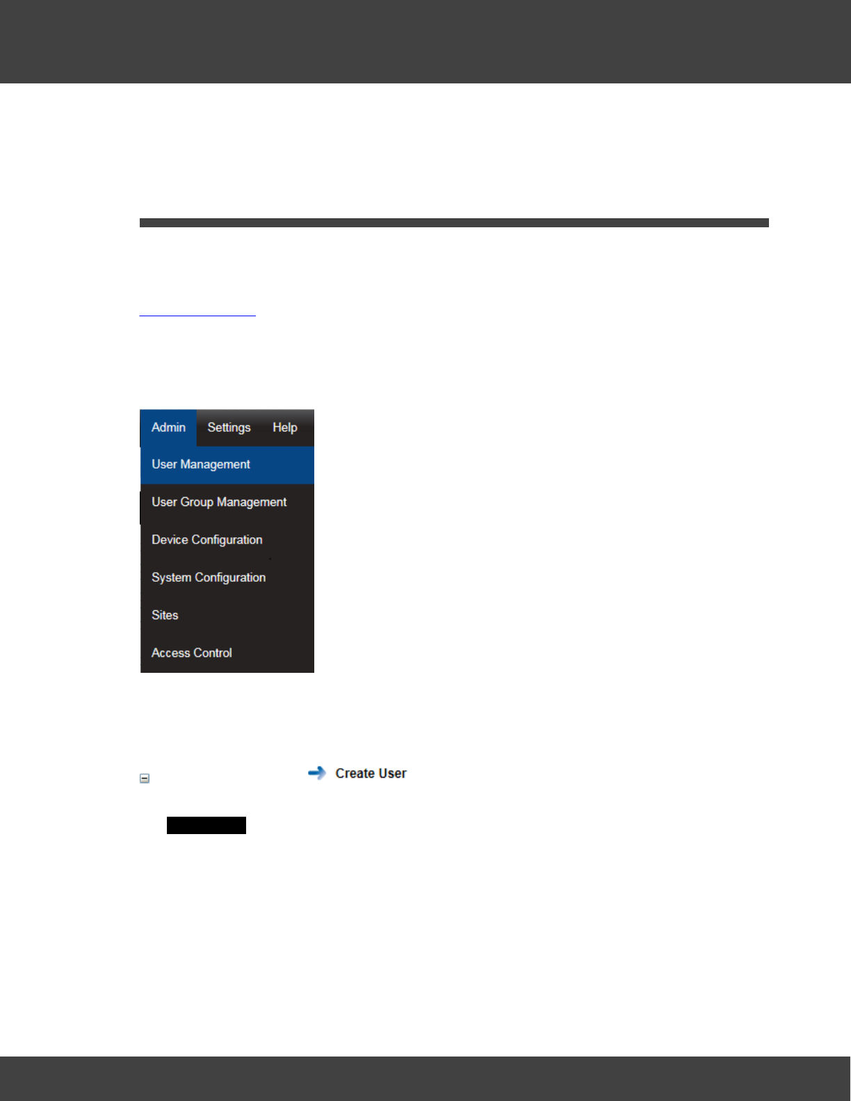
Start by selecting Admin>User Management on the main menu bar.
Note: you can only use the options under the Admin menu if you are a System
Administrator user.
You can:
Create New Users
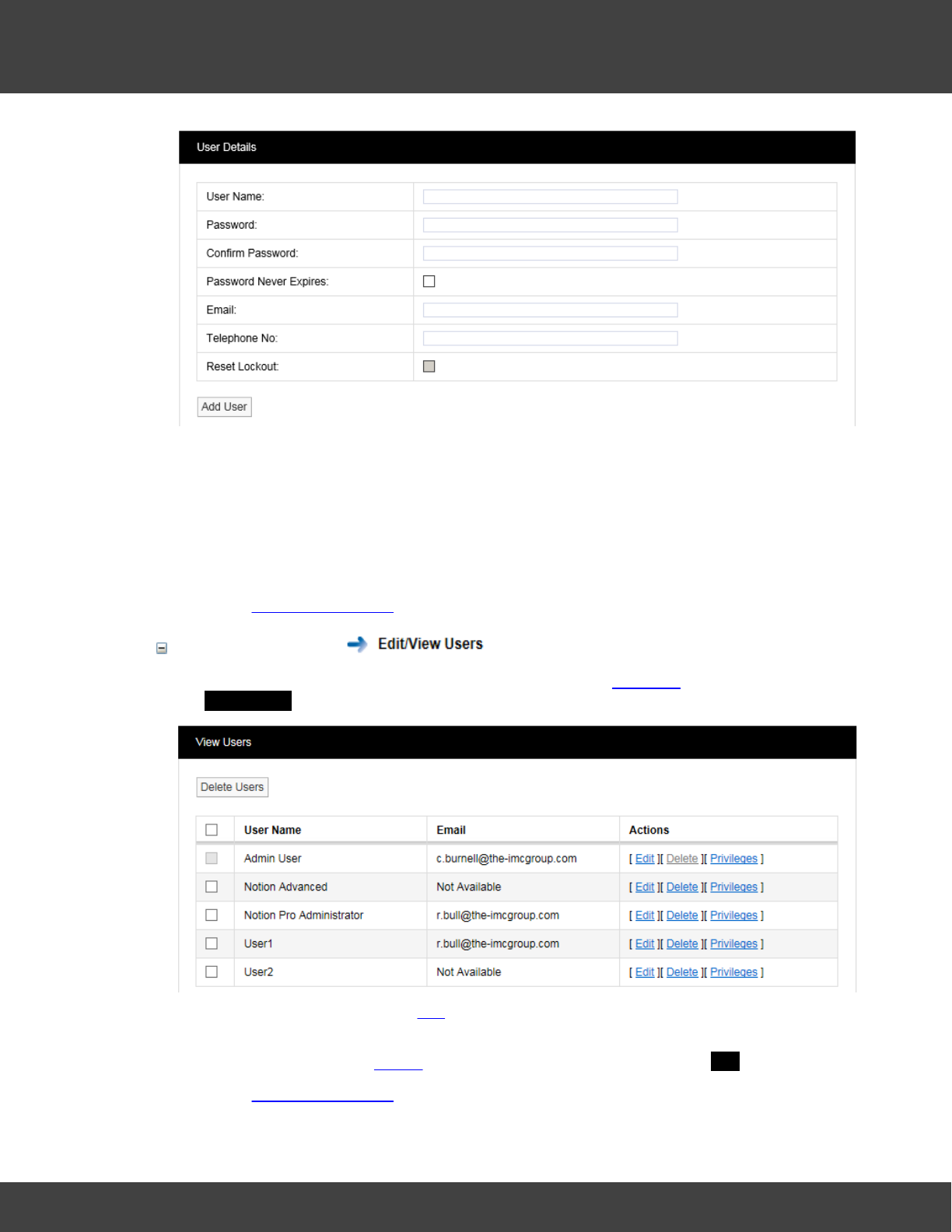
You can create new users and set their name, role, email address and phone number. In
the User Details dialog box:
22
Notion Pro © 2017 IMC Group Ltd HP5525 Version 1.2.15
How To . . .
1. Enter the user’s Full Name (for example, Robert Bull), User Name (for example
RBull), Password, email address and mobile phone number (optional). A password
must have at least four characters (eight recommended) and contain one number,
one letter, one uppercase letter.
2. When you are sure the details are correct, select Add User .
3. Repeat for all Notion Pro Users on your Site. All User Names must be different.
See also: User Management.
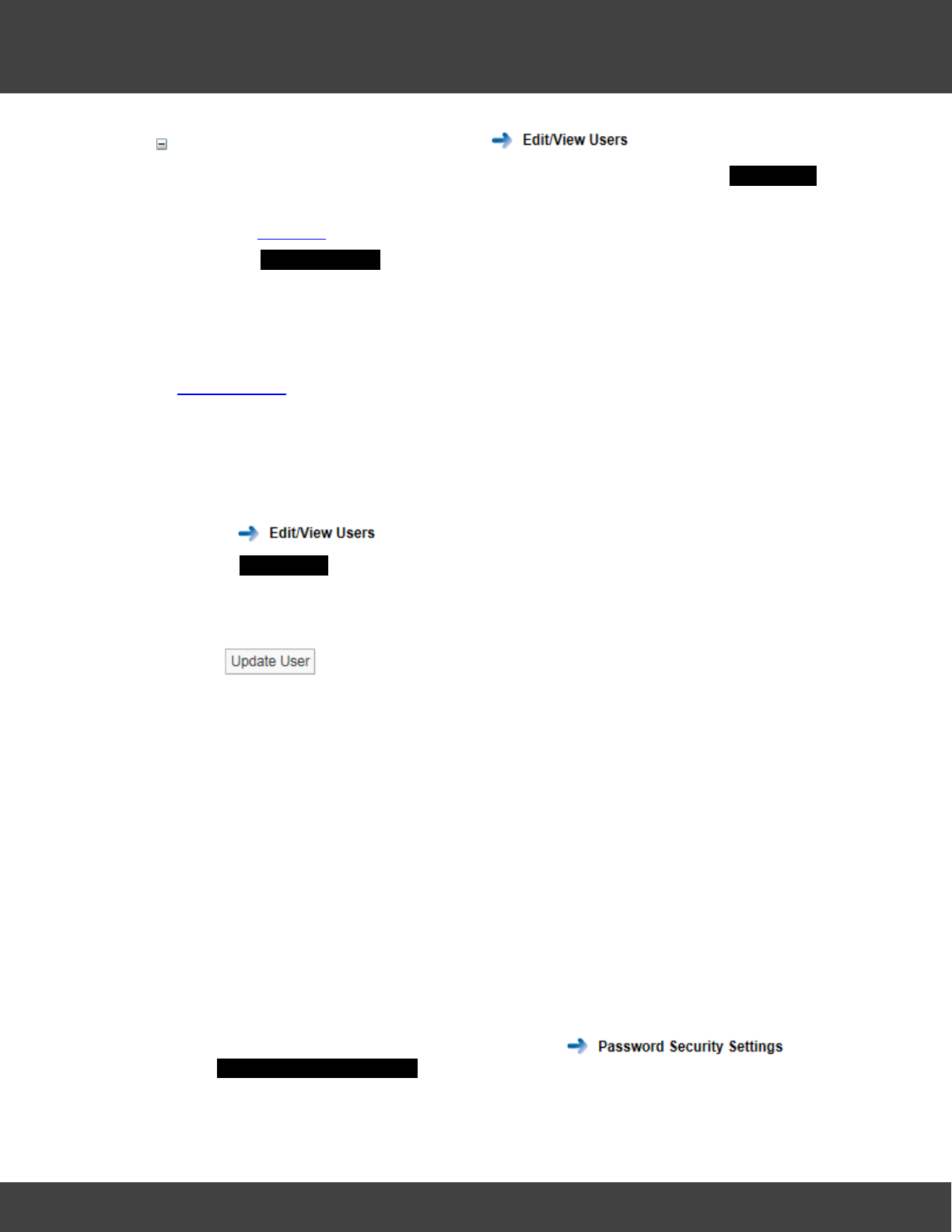
Edit Existing Users
You can list users, edit user attributes, delete users, assign privileges to users. From the list
in the View Users dialog box:
·To edit user attributes click Edit for the User you wish to edit, click Update User when
finished.
·To delete a user click Delete for the User you wish to delete, click YES to confirm.
See also: User Management.
23
Notion Pro © 2017 IMC Group Ltd HP5525 Version 1.2.15
How To . . .
Assign Viewing Privileges to a User
You can control which Sites and Zones a User can see. From the list in the View Users
dialog box:
1. Select Privileges for the appropriate user.
2. In the Assign Privileges dialog box, select the Sites, Subsites and Zones that you
would like the selected user to be able to see.
3. Click Assign Site Access.
See Also:
User Privileges
4.1.1.2 Change a User's Password
If you want to change a user's password, proceed as follows:
1. Select Admin>User Management.
2. Select .
3. In the User Details dialogue box, make sure the Keep Old Password tick box is clear.
4. Enter the new password in the Password box.
5. Enter it again in the Confirm Password box.
6. Click .
Notes:
·An ordinary user cannot change his/her own password. Only a System Administrator can
do this.
·It is recommended that a password be at least eight characters in length and contain at
least one number, one letter, one uppercase letter.
4.1.1.3 Set Password Security
The password security features allow the System Administrator to set the password length,
expiry time and other password attributes. The security settings apply to all users.
1. Select Admin>User Management, then select to give
the Password Security Settings dialogue box.

24
Notion Pro © 2017 IMC Group Ltd HP5525 Version 1.2.15
How To . . .
2. Set the variables in this dialogue box to the values agreed for your Installation.
3. Click .
See Also:
User Management.
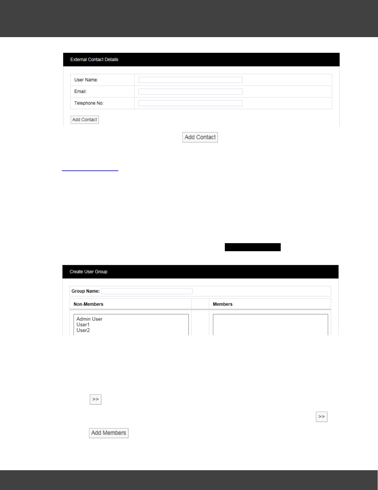
4.1.1.4 Create External Contacts
External Contacts are used when there is a requirement to email Reports or send SMS alarm
messages to people who are not Notion Pro users. The details of these people need to be
entered into Notion Pro. Select to give the External Contact
Details window.
25
Notion Pro © 2017 IMC Group Ltd HP5525 Version 1.2.15
How To . . .
Enter the necessary details then select .
See Also:
User Management.
4.1.1.5 Create and Populate User Groups
You can separate Users into User Groups. User Groups allow Privileges to be set, so
that only members of a given User Group will have the privilege to be able to view data
relating to the User Group. Users added to a Group inherit the viewing privileges associated
with that Group.
1. Select Admin>User Group Management. The Create User Group dialogue box
appears.
(In this example, two new Users, named User1 and User2 have been created. None of
them are members of a Group yet.)
2. Enter a name for the Group into the Group Name: field.
3. Select a user in the Non-Members list who you want to be member of the named
Group.
4. Click .
5. Repeat as necessary (or hold down the Ctrl key while selecting users, then click ).
6. Click .
26
Notion Pro © 2017 IMC Group Ltd HP5525 Version 1.2.15
How To . . .
Note: You can define a Group to correspond to physical location on a Site. Another
approach would be to define and name Groups by sensor type, for example, a
Group for all temperature sensors or a Group for all humidity sensors (or a Group for
all temperature and humidity sensors).
See Also:
User Group Management.
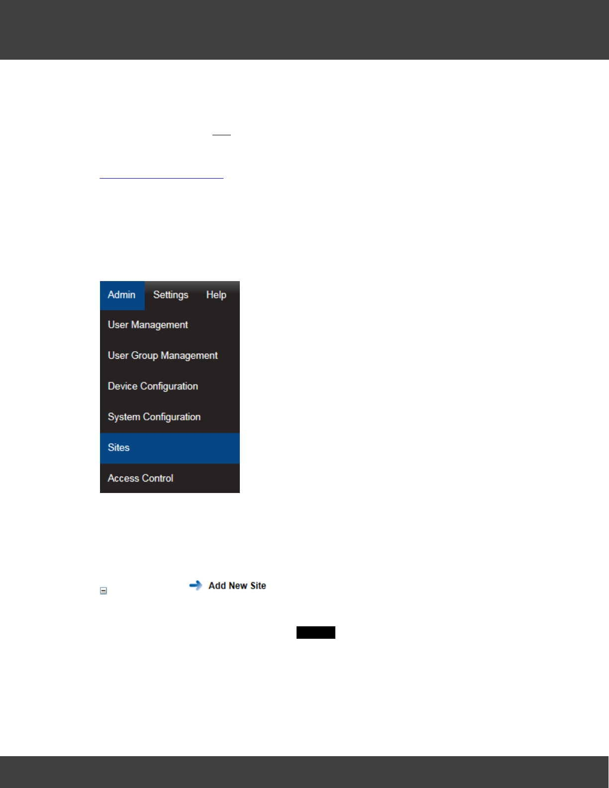
4.1.1.6 Create Sites and Subsites
You will have created a Site and given it a name as part of the ‘Creating a New Database’
steps in the Installation Procedure. We will refer to this Site as ‘YourSite’. YourSite will contain
a Zone called Zone 1 (created automatically by the Install Procedure.)
Start by selecting Admin>Sites from the main menu bar.
Note: you can only use the options under the Admin menu if you are a System
Administrator user.
You can:
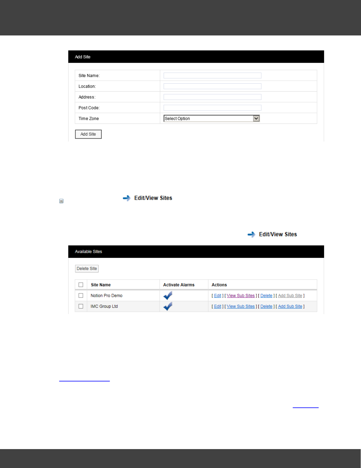
Create Sites
You can create a new Site and give it a name and location information.
1. Select Admin>Sites to give the Add Site dialogue box:
27
Notion Pro © 2017 IMC Group Ltd HP5525 Version 1.2.15
How To . . .
2. Enter the necessary details then select Add Site.
It is important to set the Time Zone correctly, otherwise Notion Pro will give false time/
date data for that Site. You must now assign Site Access to the User Groups, so that
the User Group members can see data on the Site.
Create Subsites
A Sub-Site is a subdivision of a Site. For example, a Site could be a hospital, the Subsites
could be the different units in the hospital.
1. To add a sub-site, first select Admin>Sites, then select to give:
2. Select Add Sub Site in the Actions column to give the Add Subsite dialogue box.
3. Enter the Sub Site name and other details as necessary, then select Add Subsite.
Note: you can also Edit and Delete Sites from the Available Sites dialogue box.
See Also:
Site Management.
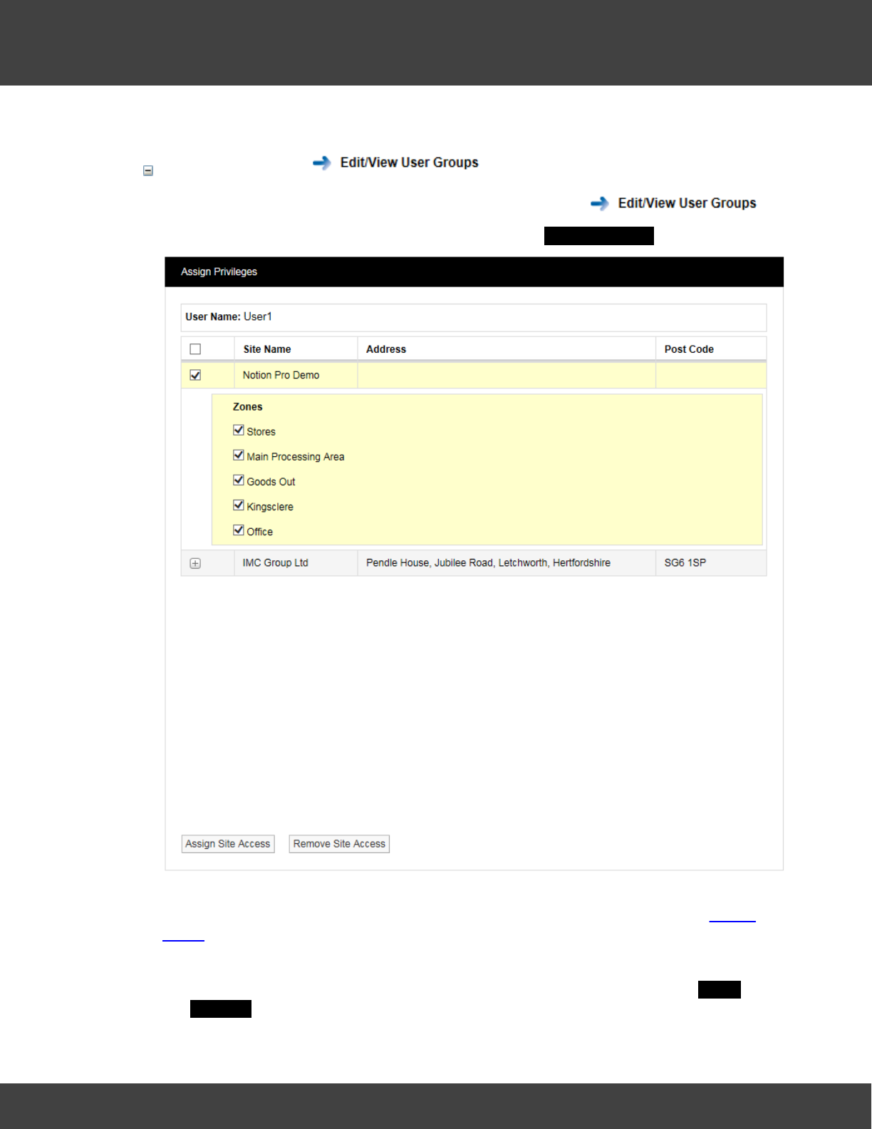
4.1.1.7 Set Access Rights
This topic introduces the procedure for assigning User access rights by assigning Privileges
to the User Groups of which the Users are members.
28
Notion Pro © 2017 IMC Group Ltd HP5525 Version 1.2.15
How To . . .
You can:
Set Access Rights
1. Select Admin>User Group Management, then select
2. Select Privileges for the required Group to give the Assign Privileges window:
Zones are commonly used to group different types of Sensor, for example you could
have a Zone for temperature sensors, a Zone for humidity sensors, etc. See Adding
Zones for how to create Zones.
3. Select the tick boxe(s) next to the required Sites and Zones.
4. Click Assign Site Access (you may need to scroll to the bottom of the Assign
Privileges window to see this).
29
Notion Pro © 2017 IMC Group Ltd HP5525 Version 1.2.15
How To . . .
See Also:
User Group Management.
4.1.1.8 Create Zones
Zones are used to logically group sensors, this could be all sensors of the same type or all
the sensors in a particular area. For example a Zone could be called RH&T Sensors which
contains all the humidity and temperature sensors, or First Floor Sensors which contains
sensors of different types but which are all on the first floor. During installation a default Site
is created. This Site contains one empty Zone called Zone1.
Note: If there is only one Site in you Notion Pro installation you will see the View Data
menu (see below) straight away, otherwise you must first select the Site of interest
starting from the Opening Display.
You can:
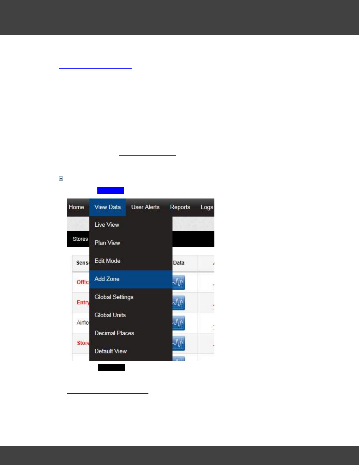
Create a Zone
1. Select Add Zone from the View Data menu, see below:
2. In the Add Zone dialogue box, enter a name for the Zone, then click Add Zone.
See Also:
Setting Up the Sensor Model.
30
Notion Pro © 2017 IMC Group Ltd HP5525 Version 1.2.15
How To . . .
4.1.1.9 Define Roles and Permissions
This topic introduces the procedures for assigning Permissions and Roles to users.
You can:
Review Permissions
These steps give an example of how the Administrator would review the Permissions of the
Site's users.
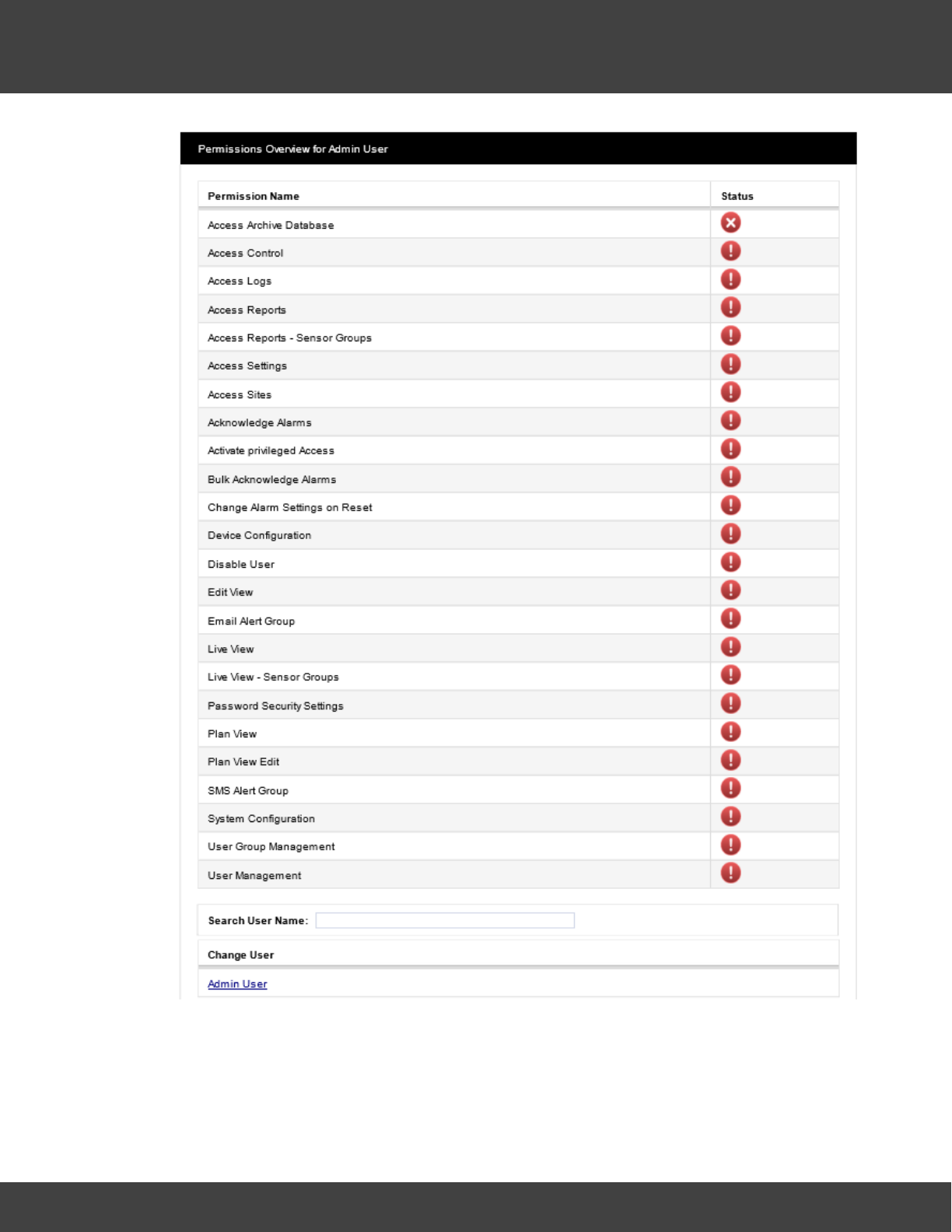
1. Select Admin>Access Control to give:
31
Notion Pro © 2017 IMC Group Ltd HP5525 Version 1.2.15
How To . . .
(shows the default Permissions for a System Administrator).
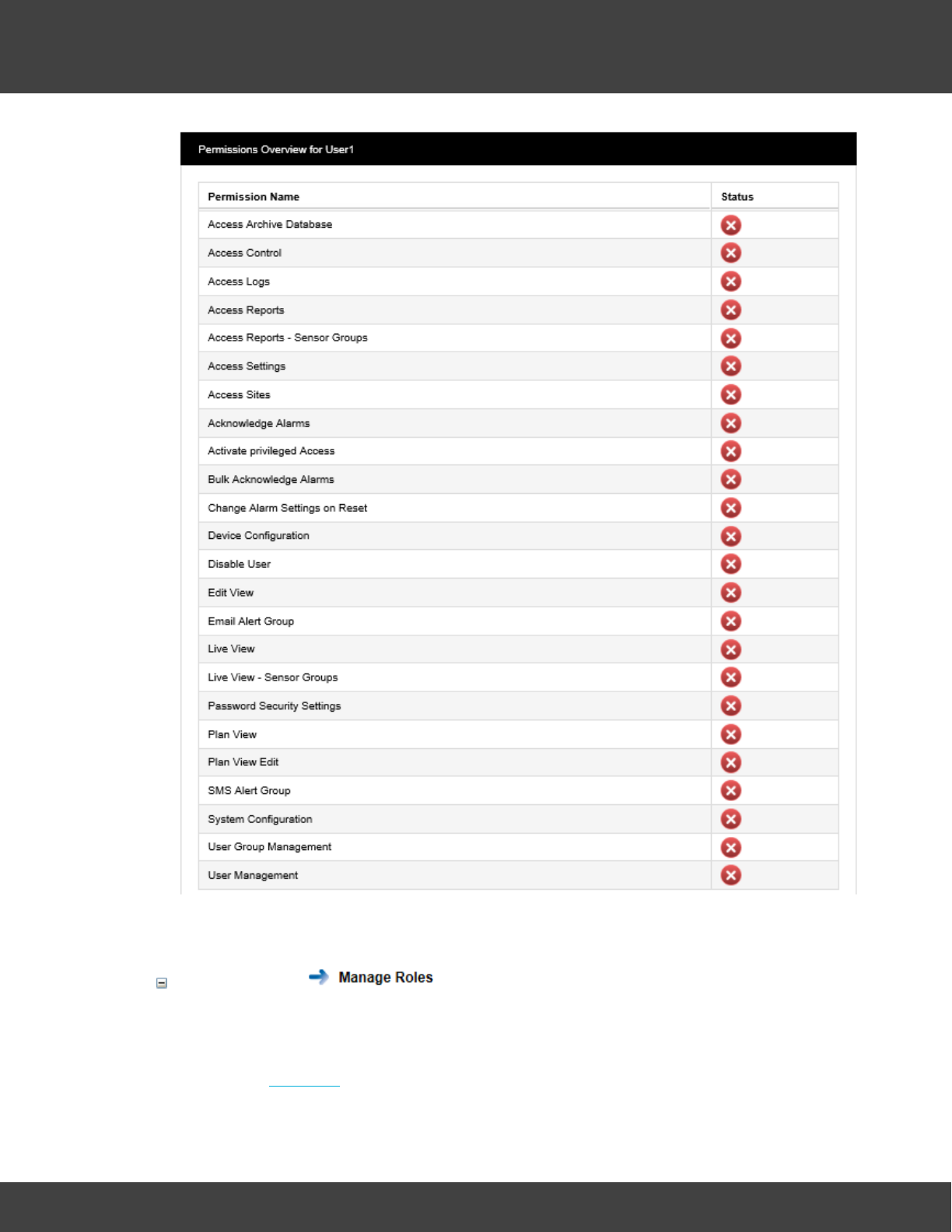
2. Click on User1 in the list at the bottom of the Permissions table to give:
32
Notion Pro © 2017 IMC Group Ltd HP5525 Version 1.2.15
How To . . .
(table shows typical Permissions for a Standard User).
Manage Roles
These steps go through an example of creating Roles.
1. Select Admin>Access Control, then select .
2. Click on New Role to give the New Role dialogue box.
33
Notion Pro © 2017 IMC Group Ltd HP5525 Version 1.2.15
How To . . .
3. Enter Advanced User into the Name: field.
4. Select the Ignore option buttons for:
·Access Control
·Access Logs
·Access Sites
·Activate privileged Access
·Disable User
·User Group Management
·User Management
Select the Allow option buttons for all other Permissions.
5. Click Save.
The Select a Role to Manage dialogue box appears, confirming that the Advanced
User Role has been defined.
Assign Roles to Users
Now you have defined some Roles, you need to assign those Roles to the Users. Most
users will probably be ‘Standard Users’. You can always ‘upgrade’ a user temporarily
(while, for example, you are on holiday) by assigning a different Role to them or by giving
them extra Permissions within their existing Role. It is assumed that you have at least
one User, one of who is called User1.
1. Select Admin>Access Control, then select .
2. In the Select a User to Manage dialogue box, click Select in the Action column for
User1 to give the ManagingUser1 dialogue box.
See Also:
Access Control
4.1.1.10 Specify email and SMS Alert Settings
This topic introduces Email and SMS Alerts and tells you how to specify them. Alerts enable
Users to be emailed with the status of Notion Pro. Alerts can also be set to enable Users to
be emailed if a sensor goes into Alarm condition (see Create Alert Groups). If your Site has
an SMS Module then users can also get text messages to inform them of alarm conditions.
Before you start
You can:
34
Notion Pro © 2017 IMC Group Ltd HP5525 Version 1.2.15
How To . . .
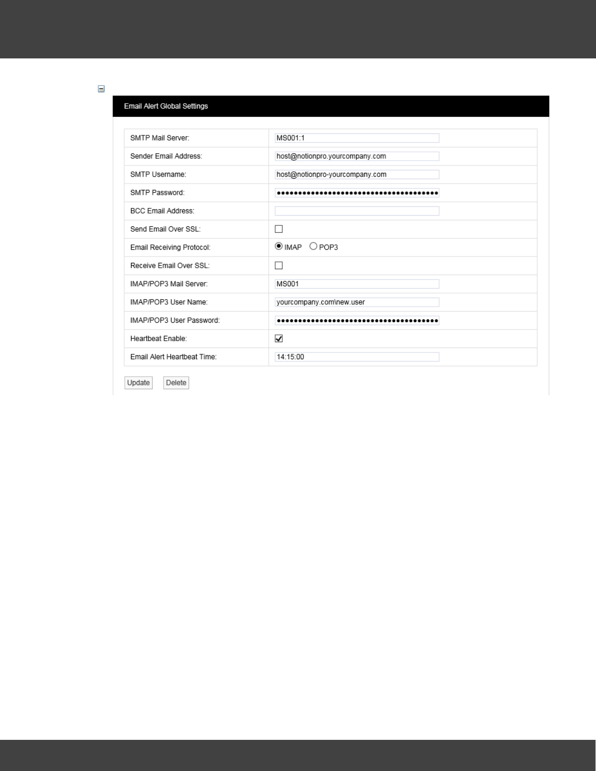
Set Up Email Alert Global Settings
1. Select Admin>System Configuration, to give:
35
Notion Pro © 2017 IMC Group Ltd HP5525 Version 1.2.15
How To . . .
Note: the above settings are for illustration purposes only and are not 'real'.
2. Fill in all the fields in the Email Alert Global Settings window, then select Update.
See Also:
System Configuration
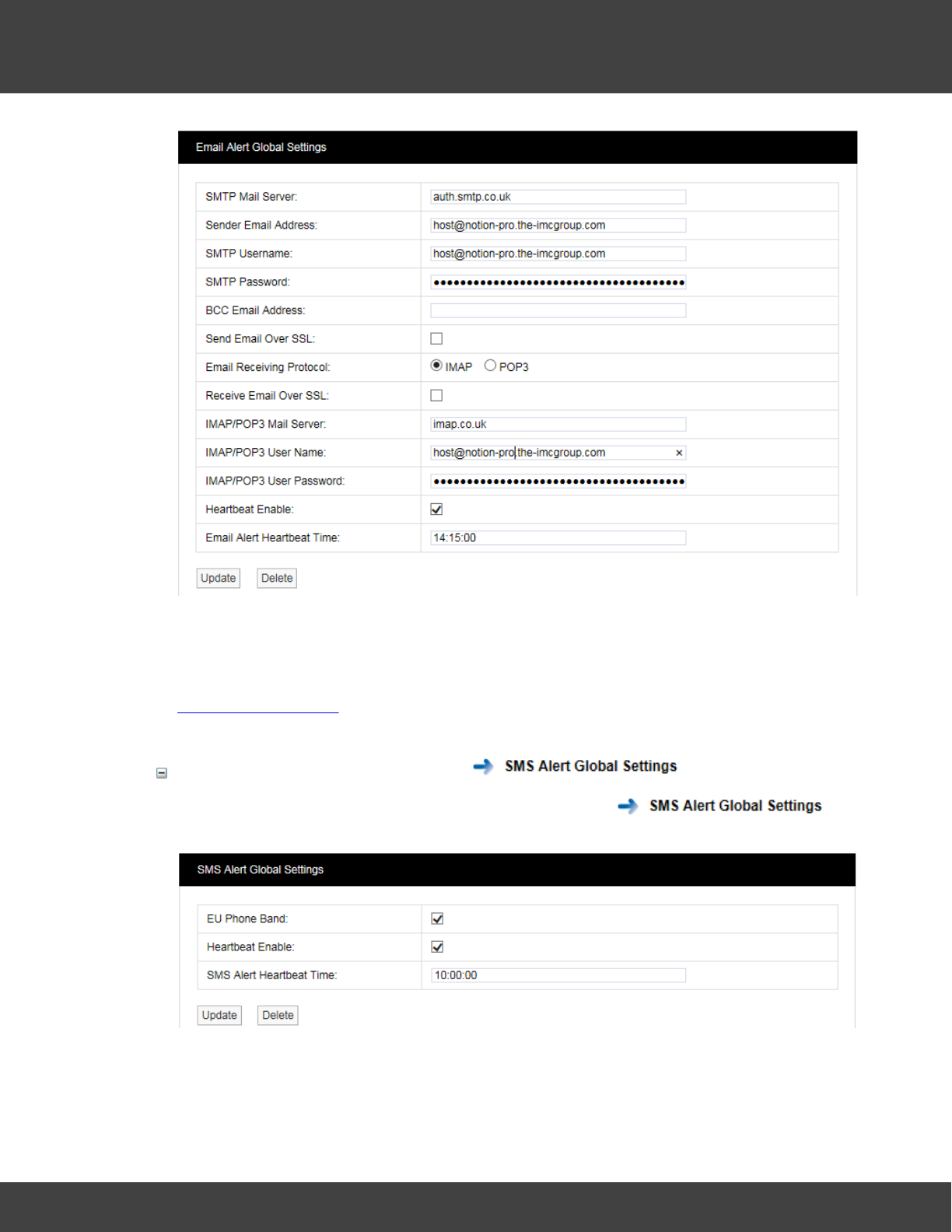
Set Up SMS Alert Global Settings
1. Select Admin>System Configuration, then select to
give:
2. When using the SMS Module anywhere using GSM900/1800, select EU Phone Band.
3. It is recommended that Heartbeat Enable is always selected.
36
Notion Pro © 2017 IMC Group Ltd HP5525 Version 1.2.15
How To . . .
4. Set the Heartbeat Time as applicable
5. Click Update.
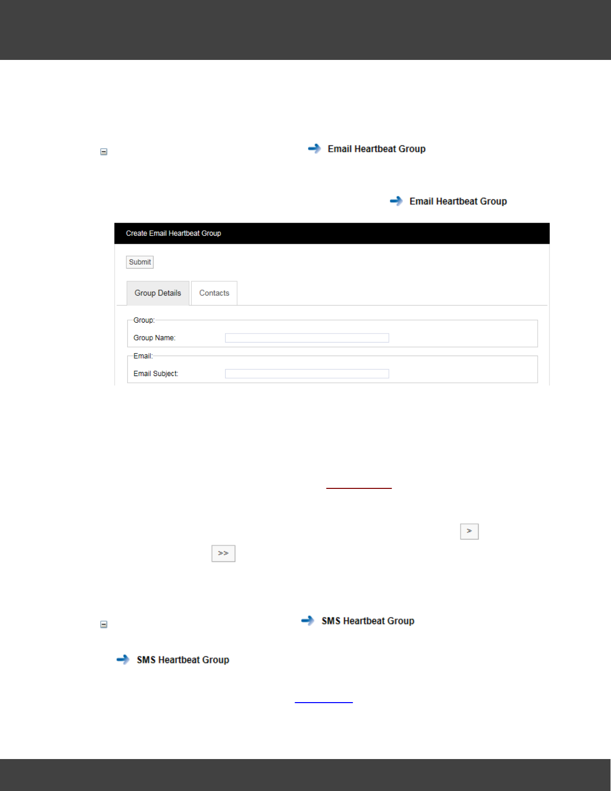
Set Up the Email Heartbeat Group
The Heartbeat Group enables several users to receive the same Heartbeat message.
1. Select Admin>System Configuration, then select to give:
2. Give the Group a Name.
3. Enter an Email Subject. This is the text to be used as the Subject line in the
Heartbeat email.
4. To specify the Users that will receive the Heartbeat message begin by selecting the
Contacts tab.
5. If no contacts have been added select Add Contacts.
6. Select the required Site from Site Name:
7. Select User names as necessary from the Source List: and click for each
selection, or click to select all Users.
8. Click Submit.
Set Up the SMS Heartbeat Group
(The procedure is very similar to setting up the Email Heartbeat group. Begin by selecting
.)
Note: to see Usernames in the Source List for SMS Contacts, you must have entered
mobile phone numbers in the User Details window for each User.
37
Notion Pro © 2017 IMC Group Ltd HP5525 Version 1.2.15
How To . . .
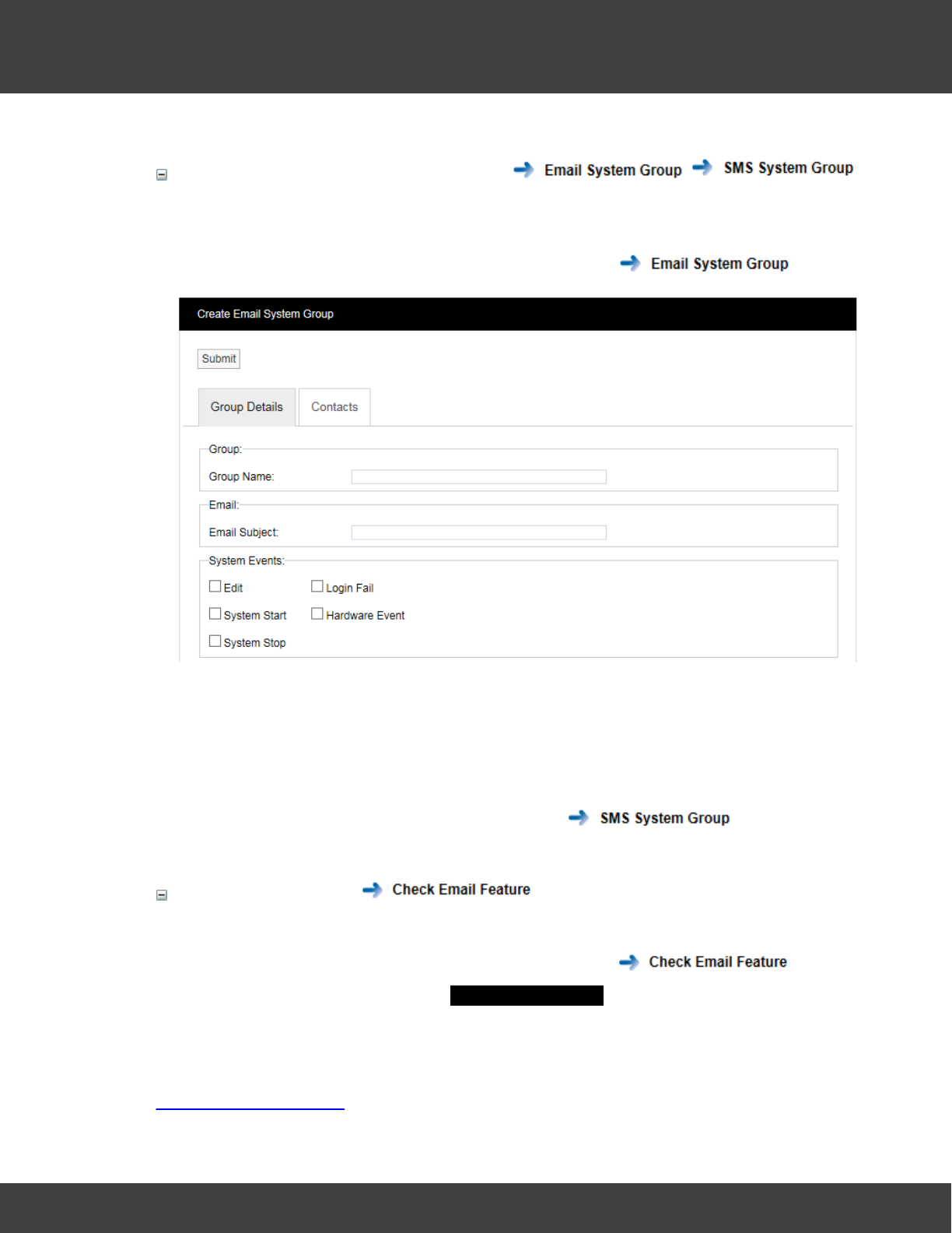
Set Up Email and SMS System Groups
The Email System group enables emails to be sent to notify users of ‘System Events’ such
as when Notion Pro starts or stops.
1. Select Admin>System Configuration, then select to give:
2. Select the ‘events’ that you need users to see from the System Events panel.
3. Click Submit.
The procedure is very similar to the procedure for creating the Email Heartbeat Group,
see above.
The procedure to create an SMS System Group is very similar to the procedure for
creating an Email System Group, start by selecting .
Check email feature
This can be used to check that the Contact email settings you have specified work correctly.
1. Select Admin>System Configuration, then select .
2. Enter an email address into the Check Email Feature window, then select Submit.
See Also:
System Configuration
38
Notion Pro © 2017 IMC Group Ltd HP5525 Version 1.2.15
How To . . .
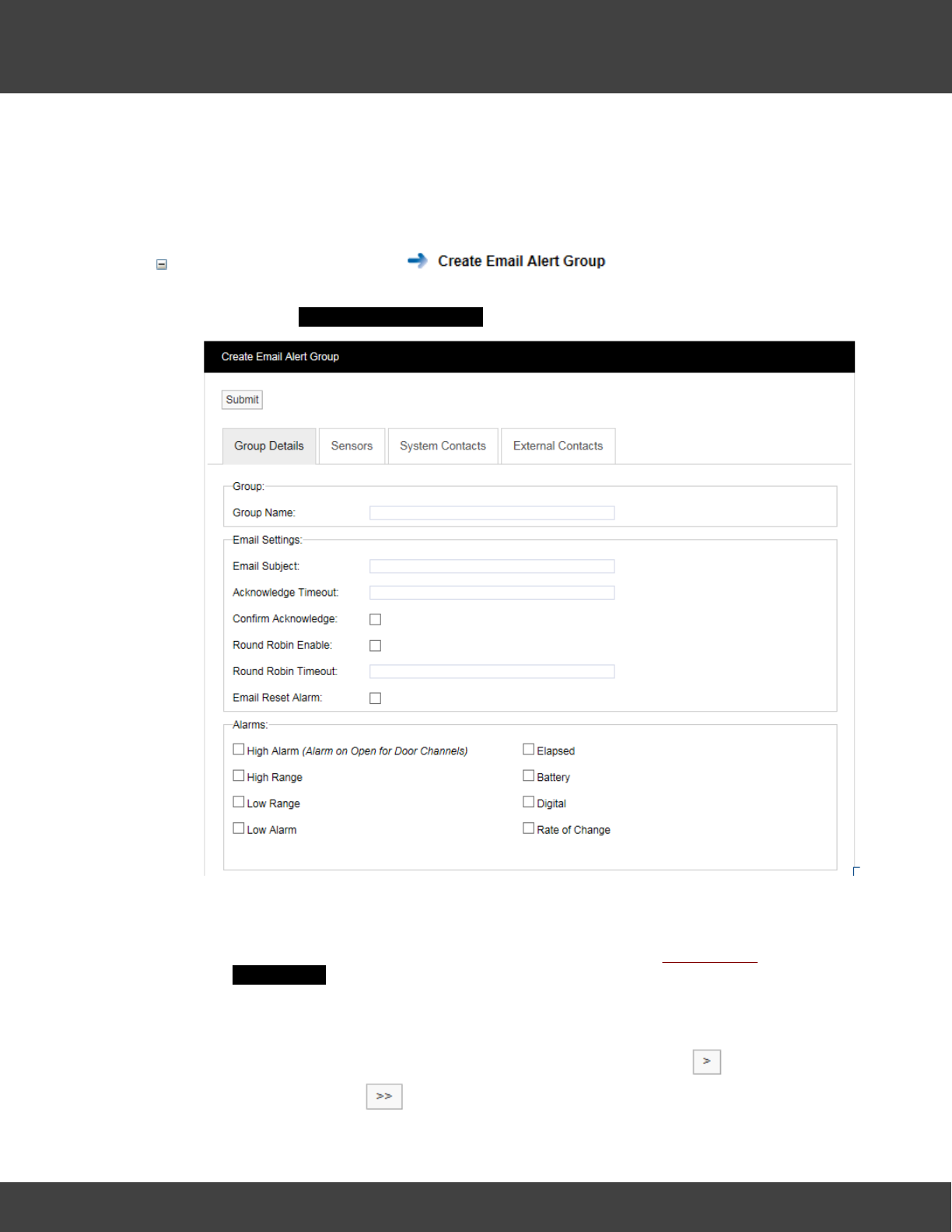
4.1.1.11 Create Alert Groups
User Alerts provide automated Alarm notification delivered via Email or SMS or both to Users
who are members of Alert Groups. (An SMS Module is required for SMS Alarms).
You can:
Create Email Alert Groups .
1. From the menu bar in the Live View, select User Alerts>E-mail Alert Group to
give the Create Email Alert Group dialog box.
2. Complete the Group Details tab as applicable.
3. Select the Sensors tab.
4. Add Sensors for which Alerts are to be sent by selecting Add Sensors to give the
Add Sensors dialog box.
5. Select the required Zone from the Zone Name: pull-down list. The Source List:
will become populated with the sensors in the selected Zone.
6. Select Sensors as necessary from the Source List: and click for each
selection, or click to select all Sensors. Select Submit when you have
39
Notion Pro © 2017 IMC Group Ltd HP5525 Version 1.2.15
How To . . .
finished specifying sensors for Alerts.
7. Select the System Contacts tab to specify the Users who are to receive the
Alerts.
6. Select the required Site from Site Name: pull-down list.
7. Select User names as necessary from the Source List: and click for each
selection, or click to select all Users.
8. Perform the same operations for External Contacts if necessary.
9. When you are satisfied with the Email Alert Group settings click Submit.
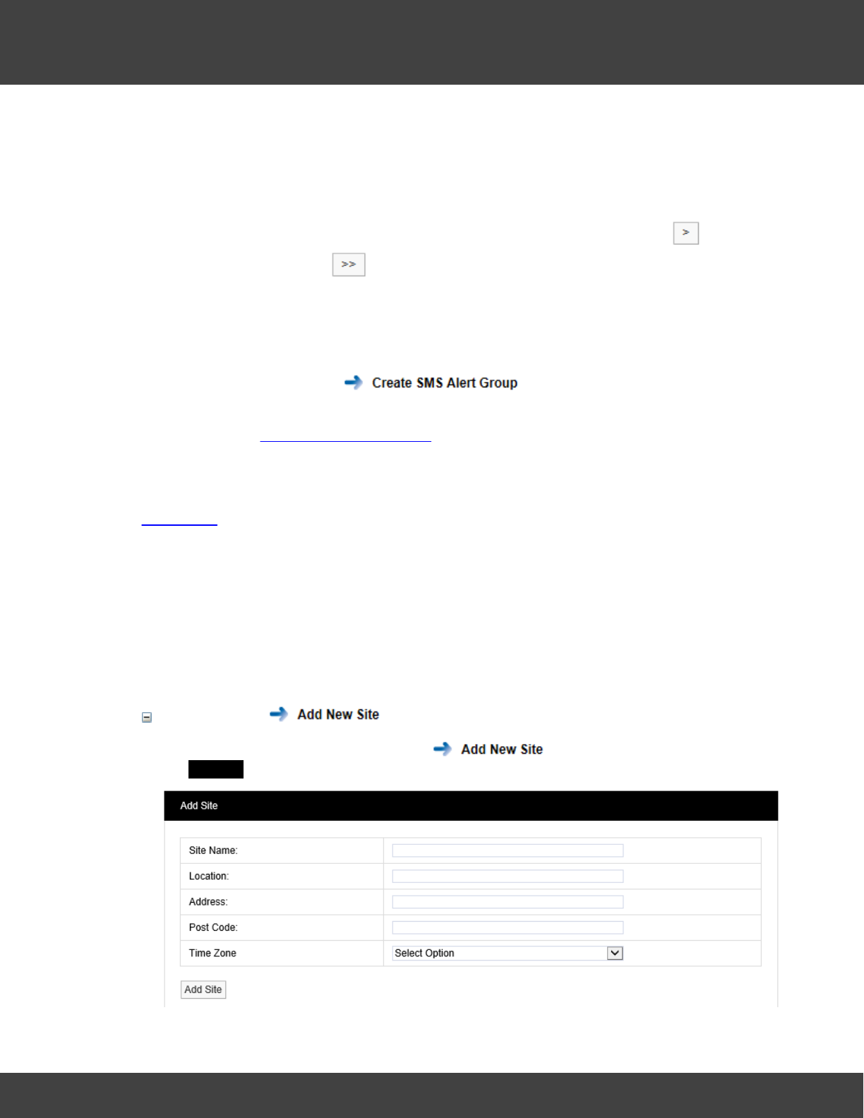
Create SMS Alert Groups
This procedure is very similar to that used to create Email Alert Groups - see above. You
must also define SMS Alert Global Settings.
See also:
User Alerts
4.1.2 Set Up Sensors
4.1.2.1 Create, Edit and View Sites
Sites are the main access points to the system data, each Site represents a single physical
Site where receiving devices such as Network Receivers or SMS Modules are located along
with Sensors. Sites can also have Sub Sites associated with the main top level Site.
You can:
Create Sites
1. Select Admin>Sites, then select from the side menu to give the
Add Site dialogue box:
40
Notion Pro © 2017 IMC Group Ltd HP5525 Version 1.2.15
How To . . .
2. Enter Site Name, Location and Address information as appropriate.
3. Select the time zone of the Site from the Time Zone pull-down menu. (The value
displayed by default is the time zone of the host PC. It is important to set this
correctly, as dates in the database are stored using GMT.)
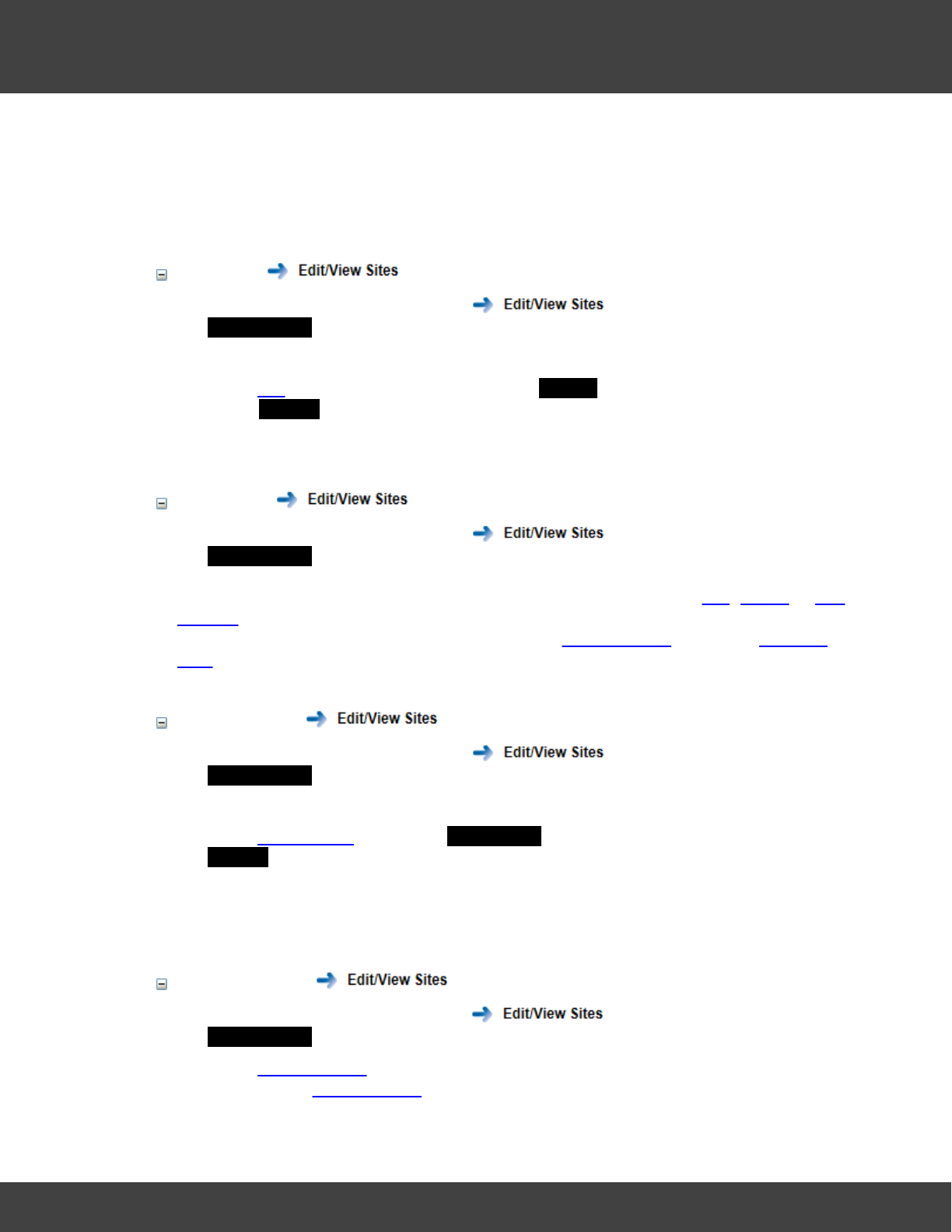
Edit Sites
1. Select Admin>Sites, then select from the side menu to give the
Available Sites dialogue box.
2. Select the tick box next to the Site you wish to edit.
3. Select Edit in the highlighted line to give the Edit Site dialogue box. This is very similar
to the Add Site dialogue box, see above.
4. Carry out the required edits, then select Update to save your changes.
View Sites
1. Select Admin>Sites, then select from the side menu to give the
Available Sites dialogue box.
The Sites that have been created are listed here. You can carry out Edit, Delete or Add
Sub Site operations from here on the selected Site. If Sub-Sites have been added to the
selected Site then you can view them by selecting View Sub Sites, otherwise View Sub
Sites will not be click-able.
Add Sub-Sites
1. Select Admin>Sites, then select from the side menu to give the
Available Sites dialogue box.
2. Select the tick box next to the Site you wish to add a Sub Site to.
3. Select Add Sub Site to give the Add Sub Site dialogue box. This is very similar to the
Add Site dialogue box, see above.
4. Enter Sub Site Name, Location and Address information as appropriate.
5. Select Add Sub Site to create the Sub Site.
View Sub-Sites
1. Select Admin>Sites, then select from the side menu to give the
Available Sites dialogue box.
2. Select View Sub Sites for the Site whose Sub Sites you wish to view. (If the Site has
no Sub Sites, View Sub Sites will not be click-able.)
41
Notion Pro © 2017 IMC Group Ltd HP5525 Version 1.2.15
How To . . .
Delete Sites
1. Select Admin>Sites, then select from the side menu to give the
Available Sites dialogue box.
2. Select Delete against the Site that you wish to delete.
3. A confirmation box is displayed for you to confirm that you wish to delete the Site.
Select YES if you are sure you wish to delete the Site, otherwise select NO.
Delete Sub Sites
1. Select Admin>Sites, then select from the side menu to give the
Available Sites dialogue box.
2. Select View Sub Sites for the Site which contains the Sub Sites you wish to delete. (If
the Site has no Sub Sites, View Sub Sites will not be click-able.)
3. Select Delete against the Sub Site that you wish to delete.
4. A confirmation box is displayed for you to confirm that you wish to delete the Site.
Select YES if you are sure you wish to delete the Sub Site, otherwise select NO.
See also:
Site Management
4.1.2.2 Configure Devices
You need to set up and configure the Notion Pro Hardware Devices to get live sensor data
from your Site. For full details of the hardware, see the IceSpy Notion Pro System Manual,
IMC doc. no. IM5521.
This section runs through what you need to do to:
·set the Database Logger service for the Network Receiver device
·set the default Network Receiver Service Port details
·add a Network Receiver device to your Notion Pro installation
·create Device Groups
You can:
Change the Database Logger Service
The DB Logger Service is the Service that passes data to the Notion Pro SQL database.
The Listening Port Name and Number are set automatically during installation, but may
be changed to suit your local IT installation if required.
42
Notion Pro © 2017 IMC Group Ltd HP5525 Version 1.2.15
How To . . .
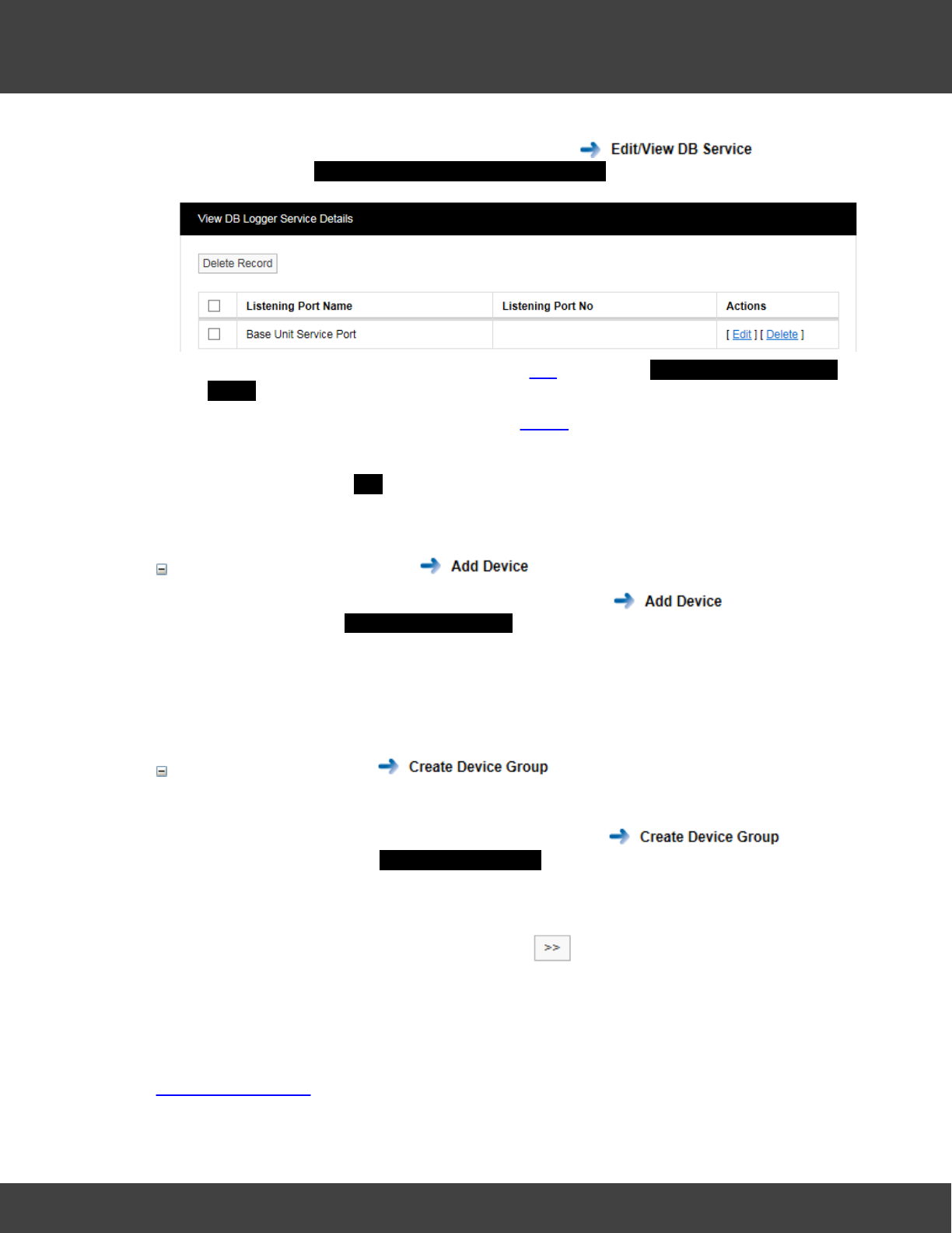
Select Admin>Device Configuration, then select from the side
menu to give the View DB Service Logger Service Details dialog box, for example:
1. To change the Logger Service details click Edit to give the Database Logger Service
Details dialog box. Make changes as required, then click Update Details.
2. To delete the Logger Service details click Delete for the relevant Service Port entry.
Alternatively, select the tick box for the relevant entry, then click Delete Record. In
both cases a confirmation box is displayed for you to confirm that you wish to delete
the Service. Select YES if you are sure you wish to delete the Service, otherwise
select NO.
Add a Device to Notion Pro
1. Select Admin>Device Configuration, then select from the side
menu to give the Control Device Details dialog box.
2. Enter the device details as required. In particular, you must select the Device Type
and Installation Site from the appropriate pull-down menus.
3. When you have entered all the necessary details, click Add Device.
Create a Device Group
You must have a Device Group, even if there is only one Receiver Device at your Site.
1. Select Admin>Device Configuration, then select from the
side menu to give the Create Device Group dialog box.
2. Give the Group a name, then select the Device Type from the pull-down menu. The
available devices of that type will appear in the Non-Members list.
3. Select a device by highlighting it, then click to move it across to the Members
column.
4. Click Add Members to create the Device Group.
See also:
Device Configuration
43
Notion Pro © 2017 IMC Group Ltd HP5525 Version 1.2.15
How To . . .
4.1.2.3 Add Sensors
We have already gone through the steps to create Zones.
This section goes through the steps to add Sensors to Zones. At this point it would be
advisable to record, in a table, attributes of the sensors you intend to add to Notion Pro.
Note: the examples in this section are for Temperature sensors or Humidity sensors (or
for sensors which measure both Temperature and Humidity). Notion Pro supports
other sensor types, the displays for those sensors will be slightly different to those
shown here.
You can:
Add Sensors
1. From the System Overview select View Data for the Site which contains the Zones
that you with to add sensors to. The Live View display has the name of the currently
selected Zone at its top left corner.
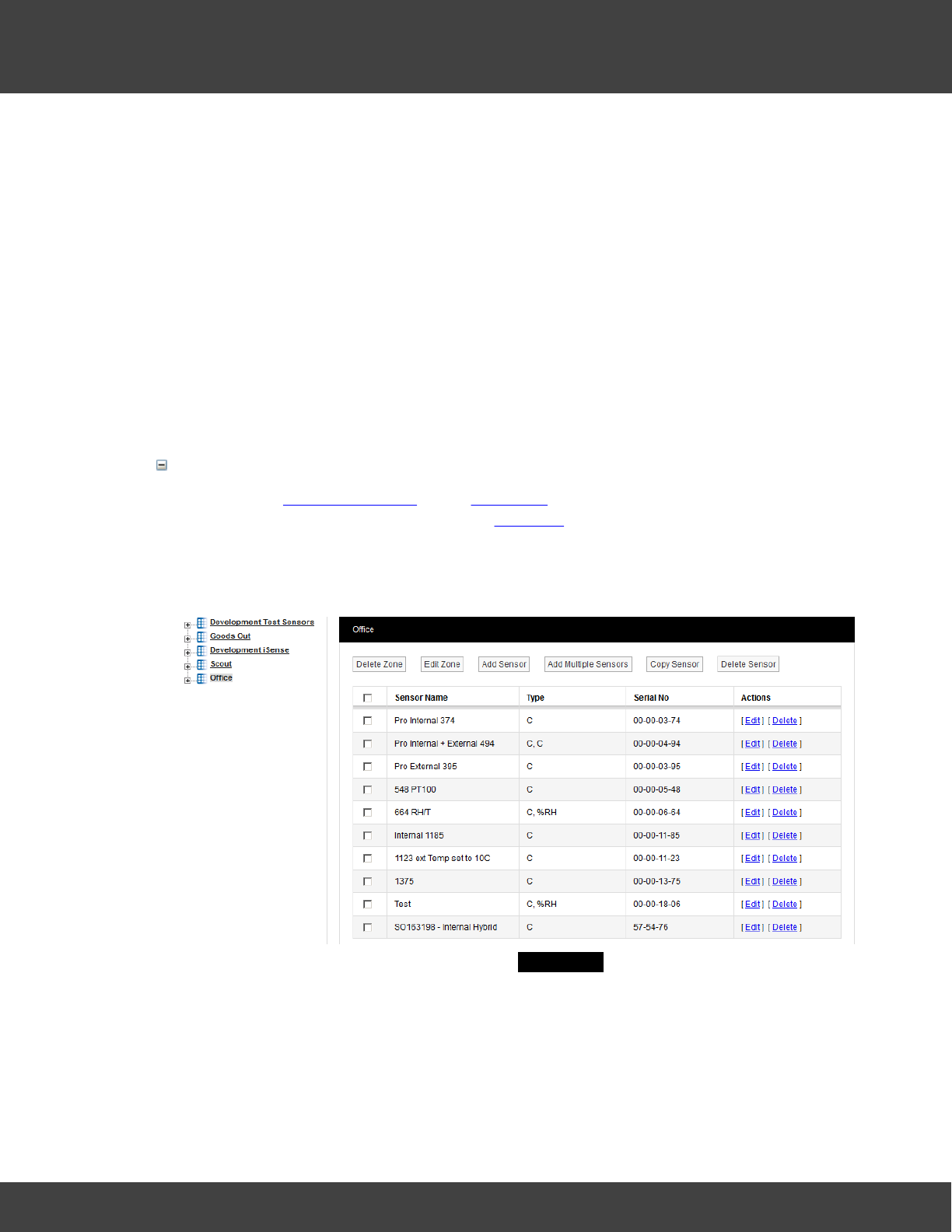
2. Select View Data>Edit Mode from the menu bar to give a display similar to that
shown below:
3. Select Add Sensor to Zone to give the Add Sensor dialog box.
4. Using the table referred to earlier, enter details of the sensor you wish to add. Sensor
Type and Device Group are selectable from pull-down lists. Serial number is on the
back of the transmitter.
5. When you have entered all the details you require, select Add Sensor.
6. Repeat the above steps for all the sensors you intend to add to the current Zone.
44
Notion Pro © 2017 IMC Group Ltd HP5525 Version 1.2.15
How To . . .
Multiple sensors of same sensor type can also be added by selecting Add Multiple
Sensors, this feature is useful for adding sensors in a batch.
You can also sort sensor records by clicking Sensor Name heading.
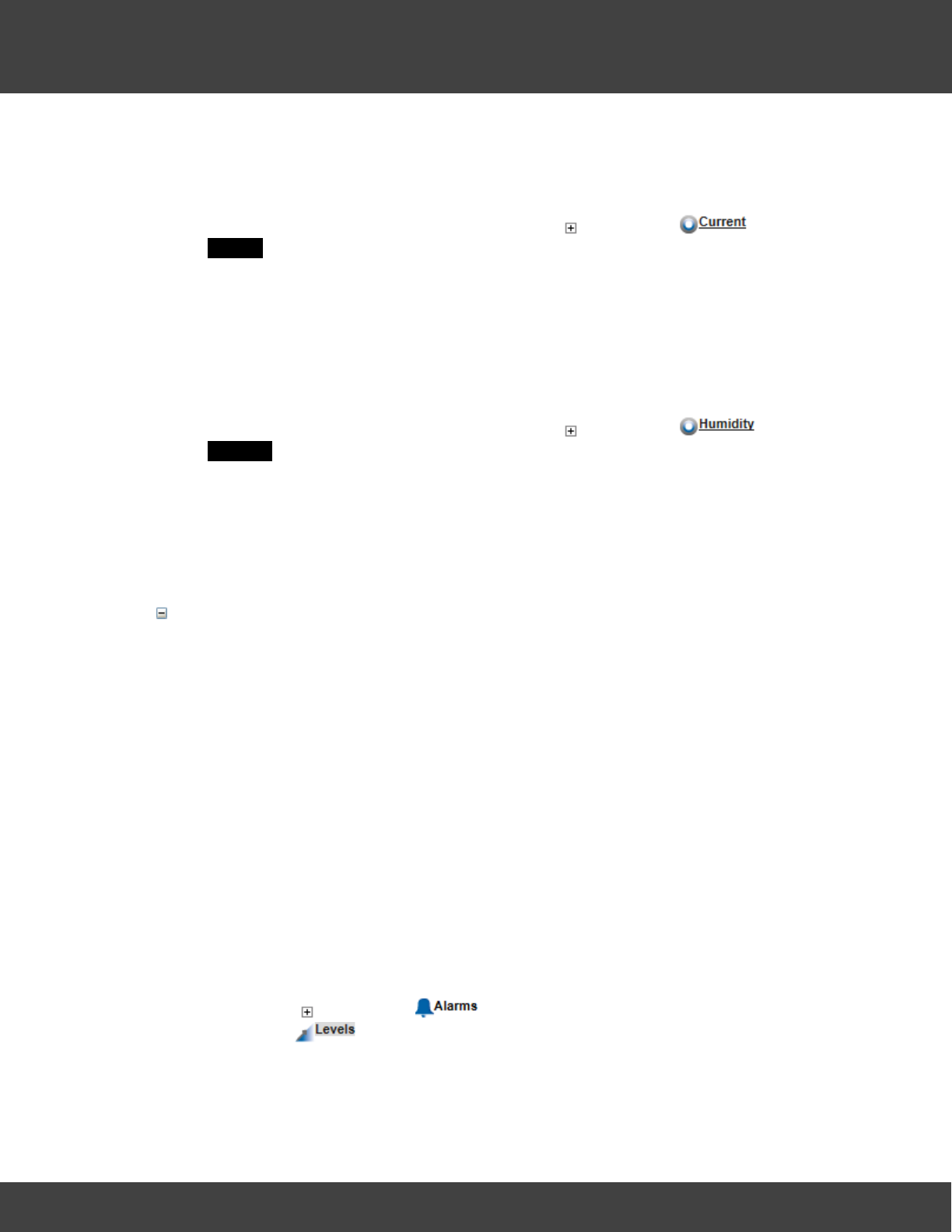
Configure Sensors
You may need to change the sensor properties from the pre-set default values. These
properties include General Settings, Calibration, Alarms and Filters. See Adding Sensors for
full details of sensor configuration.
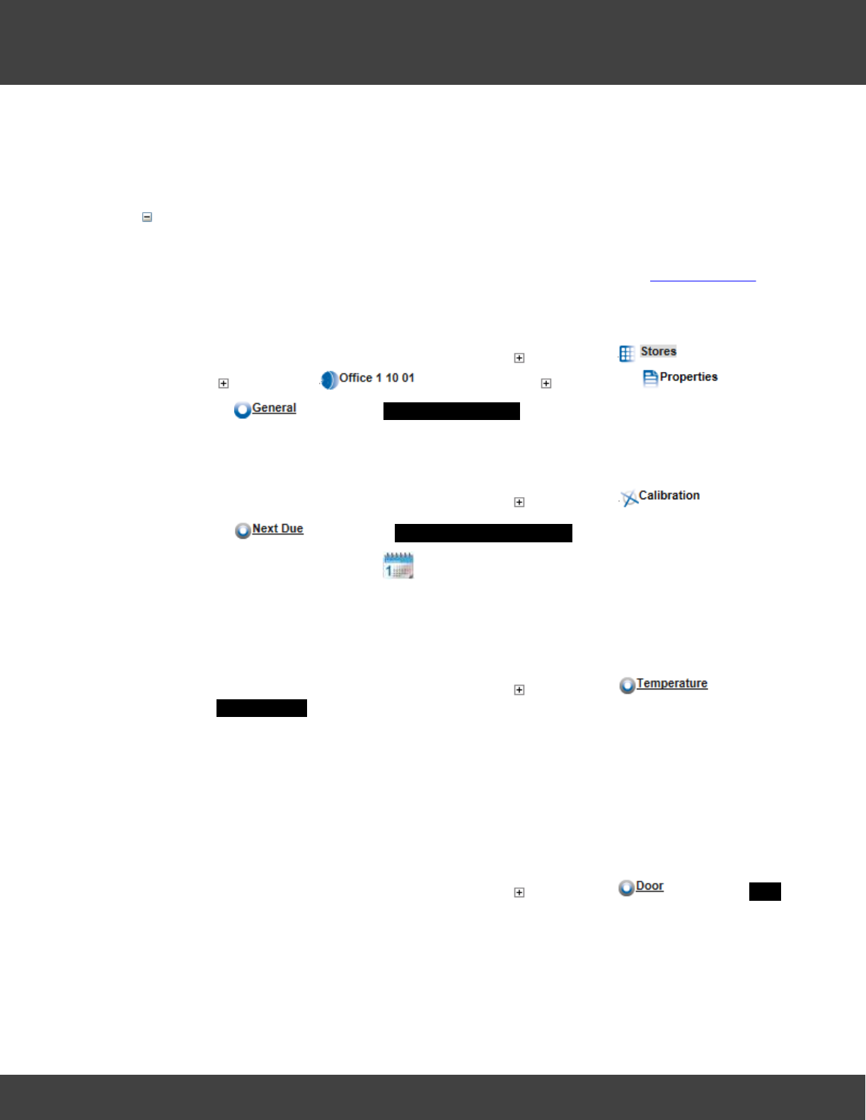
Accessing Sensor Properties
1. Continuing with the example above, select the sign next to , then select
the sign next to , finally select the sign next to .
2. Select to give the General Information dialog box.
3. Set properties as required.
Calibration Properties
1. Continuing with the example above, select the sign next to .
2. Select to give the Next Calibration Due Date dialogue box.
3. Select a new date from the tool.
4. Select Update .
5. Repeat as necessary for all sensors in all the Zones on your Site.
Temperature Calibration Properties (for sensors with a temperature channel)
1. Continuing with the example above, select the sign next to to give
the Temperature dialog box.
2. If you need to change any of the default values, select the field next to the required
setting, enter the new value and select Update .
3. If you wish to return to the default settings at any time, select Set Default .
4. Repeat as necessary for all temperature sensors in all the Zones on your Site.
Door Calibration Properties (for sensors with a door monitoring and alarm function
channel)
1. Continuing with the example above, select the sign next to to give the Door
dialog box.
2. If you need to change any of the default values, select the field next to the required
setting, enter the new value and select Update .
3. If you wish to return to the default settings at any time, select Set Default .
45
Notion Pro © 2017 IMC Group Ltd HP5525 Version 1.2.15
How To . . .
4. Repeat as necessary for all door monitoring and alarm function sensors in all the
Zones on your Site.
Current Calibration Properties (for current clamp sensors)
1. Continuing with the example above, select the sign next to to give the
Current dialog box.
2. If you need to change any of the default values, select the field next to the required
setting, enter the new value and select Update .
3. If you wish to return to the default settings at any time, select Set Default .
4. Repeat as necessary for all current clamp sensors in all the Zones on your Site.
Humidity Calibration Properties (for sensors with a Humidity channel)
1. Continuing with the example above, select the sign next to to give the
Humidity dialog box.
2. If you need to change any of the default values, select the field next to the required
setting, enter the new value and select Update .
3. If you wish to return to the default settings at any time, select Set Default .
4. Repeat as necessary for all humidity sensors in all the Zones on your Site.
Set Sensor Alarm Properties
You can set basic alarm properties on a sensor as follows:
·whether the sensor is enabled to give alarms are not
·the Levels (for example, of temperature and/or humidity) above or below which an
alarm would be triggered
·the delay period (Alarm Advance) before an alarm would be raised
·the rate of change of a quantity which would raise an alarm (for example, a rapidly
increasing temperature might indicate a fire)
·the days of the week on which your sensor alarms are enabled (you may want to
turn alarms off at weekends if there is no activity on the Site).
·Filter alarms to help reduce interference
·set Notes against an alarm.
Setting Sensor Alarm Levels and other Properties
1. Click on the sign next to under the sensor for which you wish to set alarm
properties. is highlighted by default and gives a dialog box dependent on the
sensor type.
2. If you wish to change any of the default values, select the field next to the required
46
Notion Pro © 2017 IMC Group Ltd HP5525 Version 1.2.15
How To . . .
setting, enter the new value and select Update .
3. Repeat as necessary for all sensors (or all types) in all the Zones on your Site.
Other Alarm Settings
1. Select to give the Alarm Advance dialog box.
2. Adjust the values and/or set the Yes/No options as necessary, then select Update.
3. If you wish to set any notes against an alarm setting, select to give the
Alarm Notes dialog box.
4. Enter the required note in the Notes Description field, then click Add.
Filters
1. Select to bring up a dialog box which allows you specify filtered limits on data
values.
2. Enter the required minimum and maximum values, then click Update.
Define Global Settings
Global Settings allow alarm disable times and days to be set across a range of Sensors.
1. Select Global Setting on the Alarm Levels or Alarm Advance dialog box to give a
(Site-dependent) window, for example:
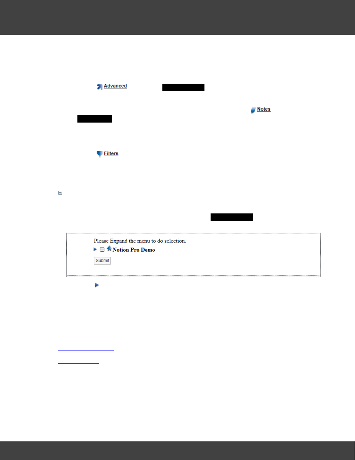
2. Click to show the Zones within the Site.
3. Select the Zones (by clicking in the box next to the Zone name) that you wish to
apply Global Settings to, then click Submit.
See also:
Adding Sensors
Configuring Sensors
Setting Alarms
4.1.2.4 Create and Edit Sensor Groups
The Sensor Groups feature is extremely useful for grouping sensors of the same type
that are measuring the same parameters.
You can:
47
Notion Pro © 2017 IMC Group Ltd HP5525 Version 1.2.15
How To . . .
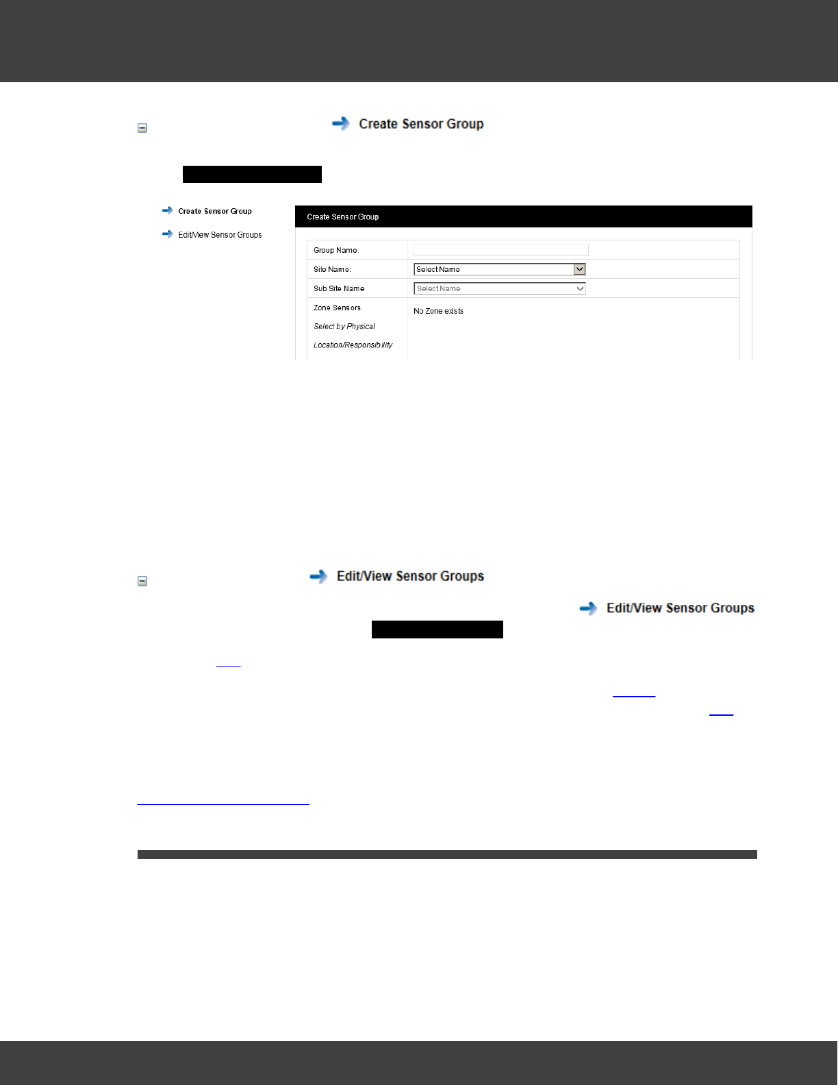
Create Sensor Groups
1. Select Settings>Customise Sensor Groups from the main menu bar to give the
Create Sensor Group dialog box, see below
2. Enter a name for the Group, for example 'Door Sensors'.
3. Select the owning Site for the Sensor Group from the pull-down list. If the Site has
Sub Sites these will now appear. Select the Sub Site if required.
4. After selecting the Site (or Sub Site) the available Zones on that Site become visible.
Select the + symbol next to the Zone name that contains the Sensors that you wish
to select.
5. When you are happy with you selections click on Create Group. The Group you
have created appears in the View Sensor Groups dialog box.
Edit Sensor Groups
1. Select Settings>Customise Sensor Groups, then select
on the side menu to give the View Sensor Groups dialog box.
2. Select Edit against the Group you wish to edit.
3. From here you can delete Sensor Groups (Delete Members, or Delete for the
selected Group), add a Sensor Group (Add Members) or edit a Sensor Group (Edit
again from under the Actions column to add or remove sensors).
See Also:
Setting Up Sensor Groups
4.2 (All Users)
All Users can:
·view live data
·check alarm statuses
·look at system logs
48
Notion Pro © 2017 IMC Group Ltd HP5525 Version 1.2.15
How To . . .
·produce reports.
The options described here are only a summary of what's available. For full information see:
Viewing Data
Setting Up and Running Reports
4.2.1 Get a Quick View of ...
4.2.1.1 sensor readings
When you log in, if your System Administrator has only given you viewing rights for one Site,
you will see something like:
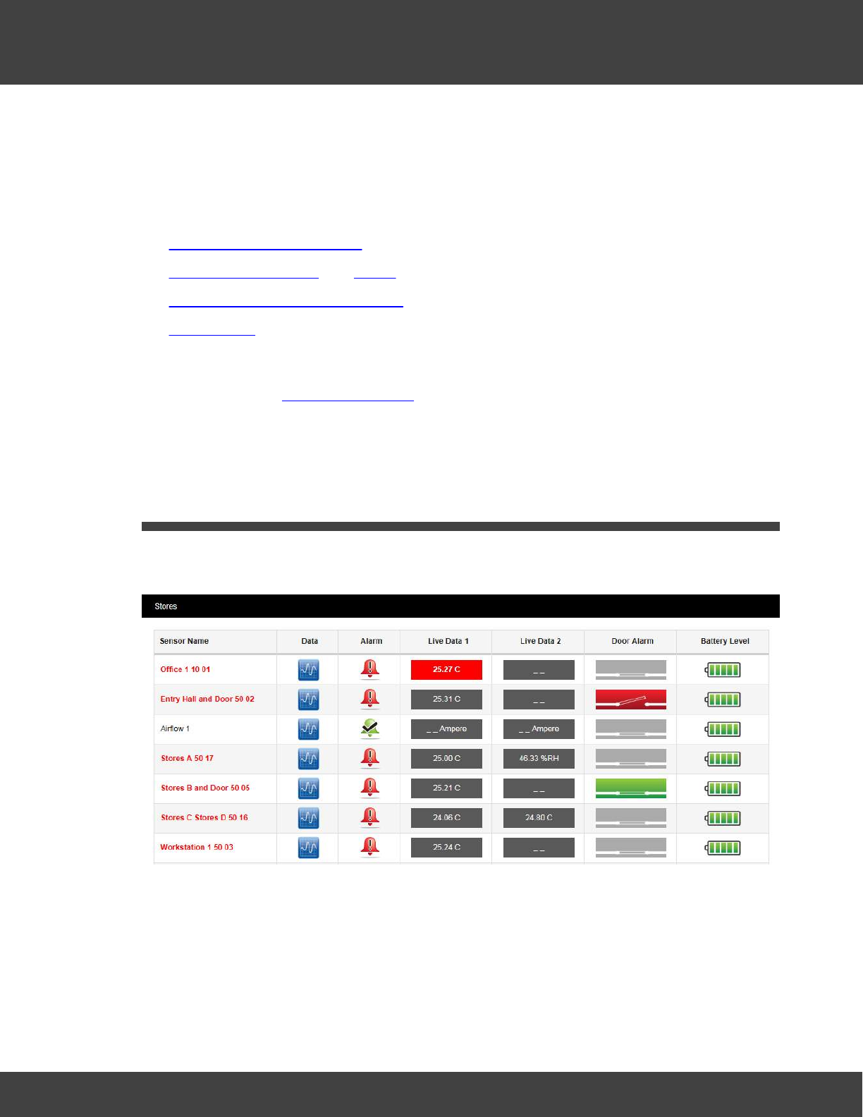
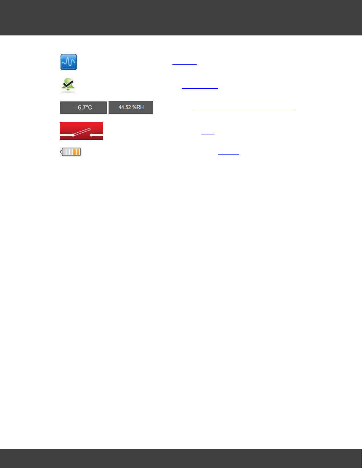
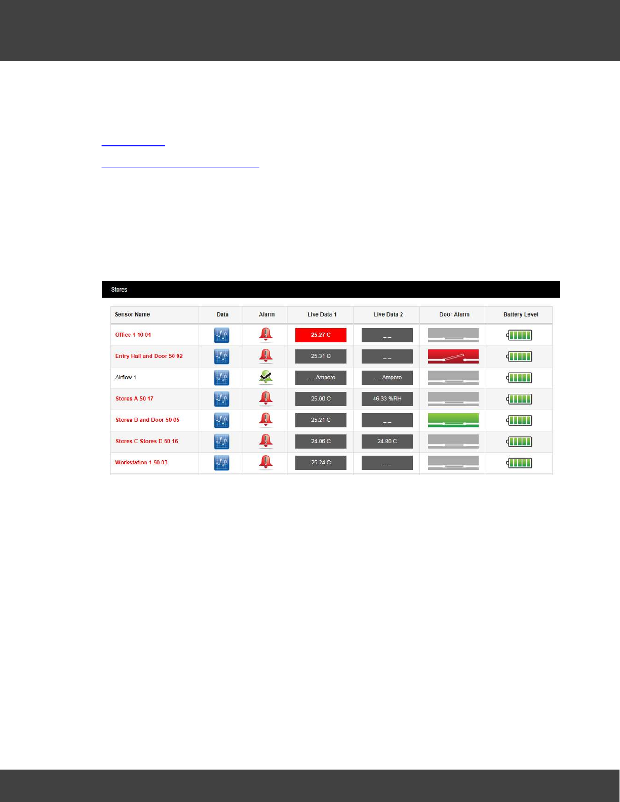
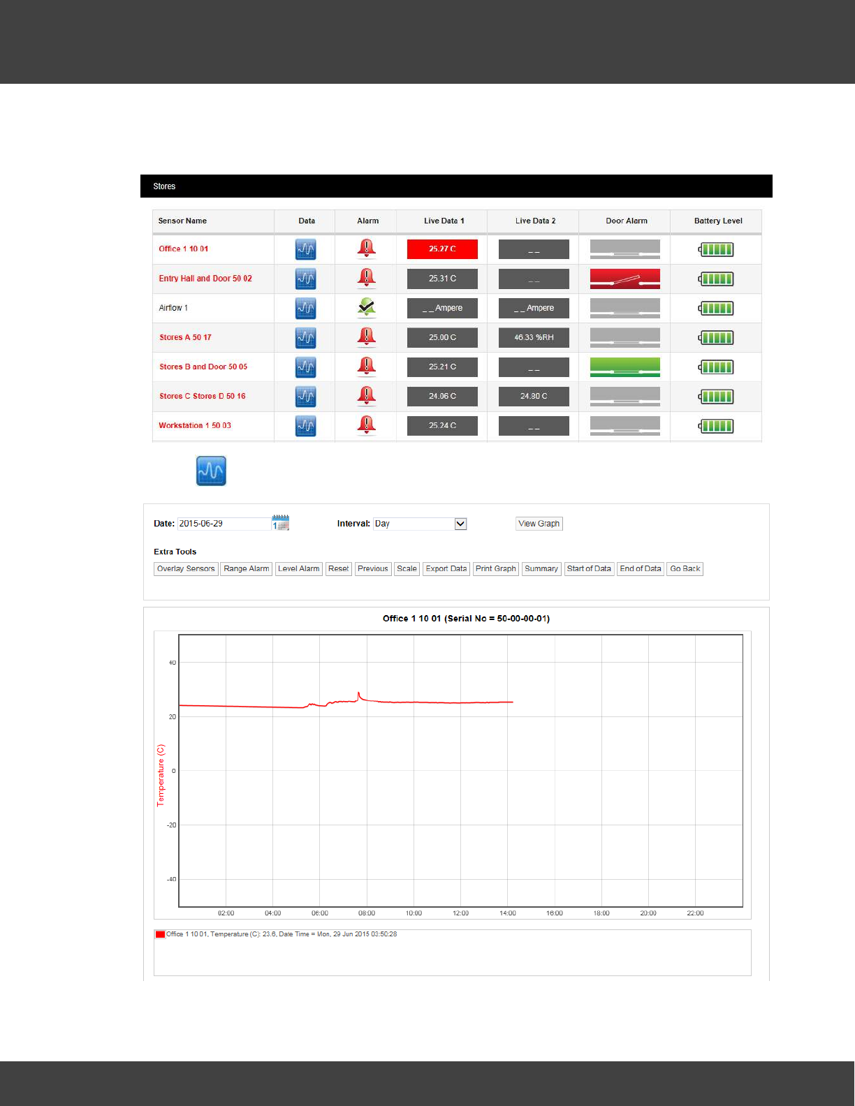
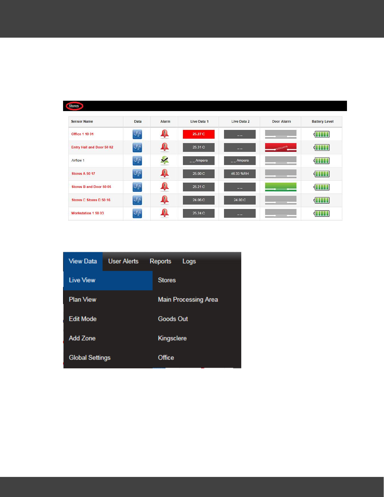
In this example (called the Live View) we see that:
·we are looking at the sensors in the 'Stores' Zone (see top left corner)
·all the sensors except one are showing an alarm
·all the sensors are showing temperature readings, except 'Stores A 50 17' which is also
showing a humidity reading, and 'Airflow 1' which is a current sensor
·somebody has left the door open in the Entry Hall
·the door is closed in Stores
·all the sensor batteries are OK.
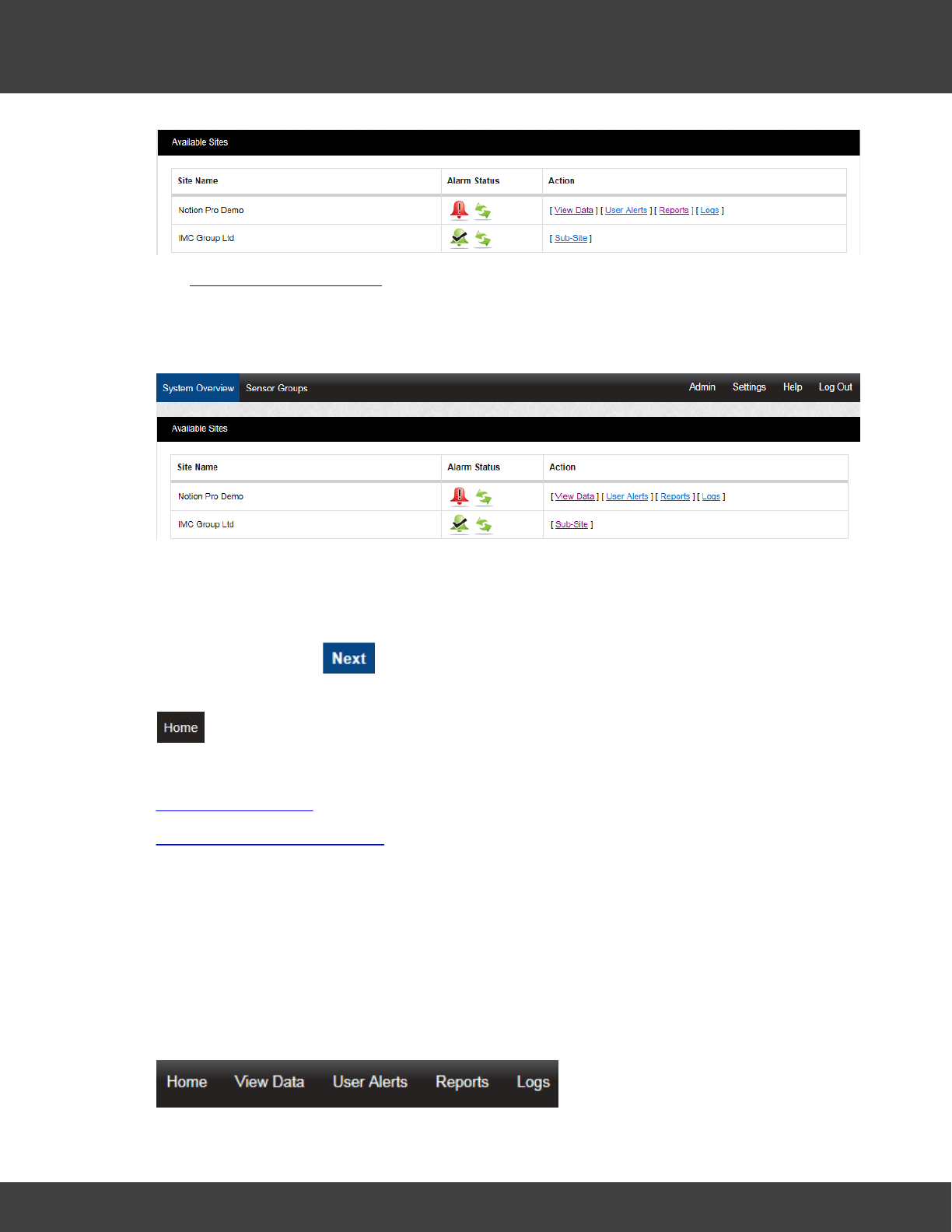
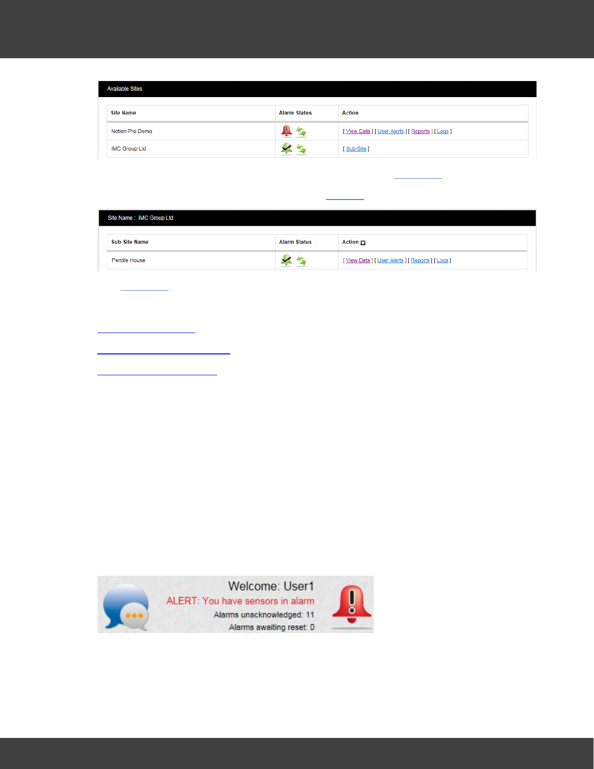
If you have you have more than one Site in your installation you will have to select the Site
of interest first. In this case, when you log in you might see something like:
49
Notion Pro © 2017 IMC Group Ltd HP5525 Version 1.2.15
How To . . .
To see the sensor data in the Notion Pro Demo Site, just click View Data.
The IMC Group Ltd Site has a Sub-Site, click on Sub-Site to see it:
Click View Data as before to see the sensor data in the Pendle House Sub-Site.
See also:
The Opening Display
The System Overview Page
Choosing the Site to View
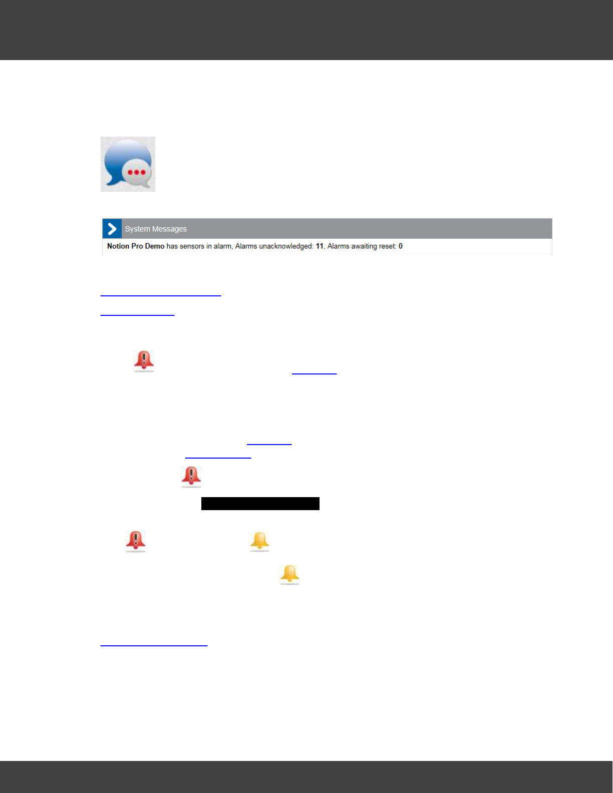
4.2.1.2 alarm statuses
When you log in, at the top right corner you will see something like:
In this example we see that:
·We have sensors in alarm.
·11 alarms are unacknowledged, 0 alarms are awaiting reset.
50
Notion Pro © 2017 IMC Group Ltd HP5525 Version 1.2.15
How To . . .
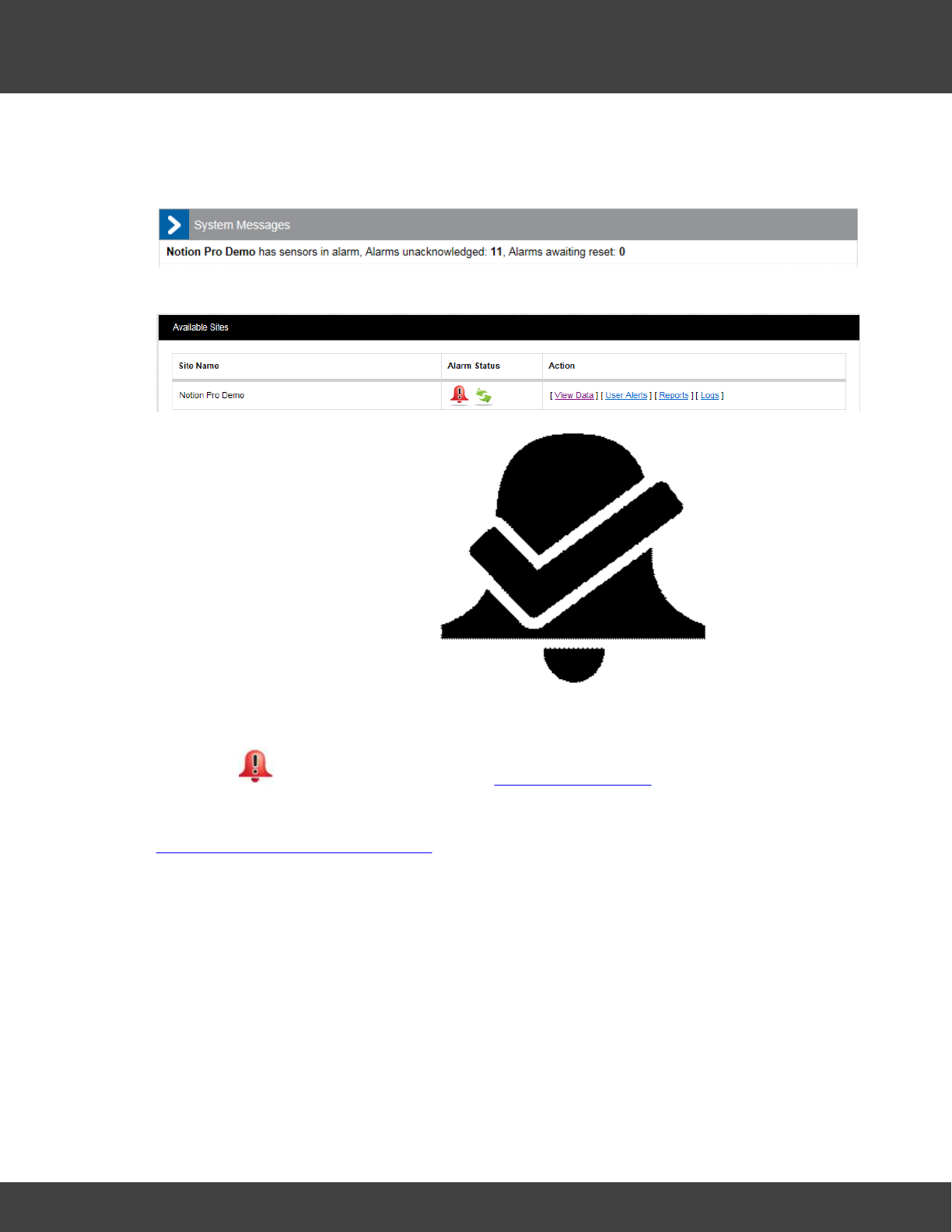
·The System Message bubble on the left is showing amber dots, which means there no
new unread system messages. To see the System Messages, click on the bubble to
show:
Clicking on the red alarm bell icon gives:
The Communication Status icon ( ) (green arrows in
this case) shows that communications to all control devices (such as Network Receivers) are
working normally.
Clicking on from this view goes back to The Opening Display
See also:
View System Alarm Status Overview
51
Notion Pro © 2017 IMC Group Ltd HP5525 Version 1.2.15
How To . . .
4.2.1.3 a sensor reading in graphical form
Starting from the Live View,
click on for the sensor of interest to give, for example:
Here, the graph shows live temperature data, starting at 00:00 for the Office 1 10 01
52
Notion Pro © 2017 IMC Group Ltd HP5525 Version 1.2.15
How To . . .
sensor.
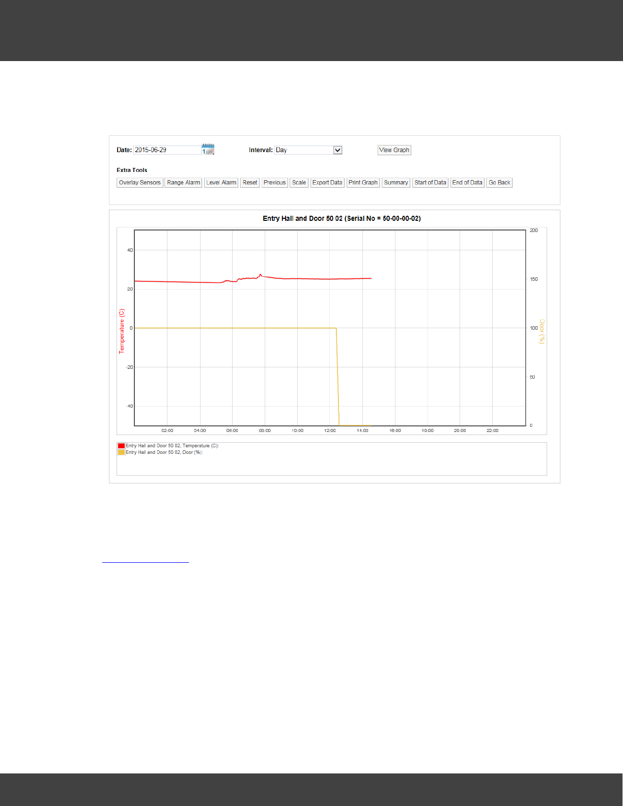
An example of a graph for a two-channel sensor might be as shown below:
Here we see temperature data in red, door data in yellow. The door had been open (and so
in an alarm state) until about 12:30, then somebody closed the door.
See also:
Viewing Live Data
53
Notion Pro © 2017 IMC Group Ltd HP5525 Version 1.2.15
How To . . .
4.2.2 Look at Sensor readings from . . .
4.2.2.1 another Zone
The name of the Zone for the current data display is shown at the top-left corner of the
Live View for the Zone ('Stores' below):
To switch the Live View display to show another Zone:
1. Select View Data>Live View:
2. Move the mouse pointer down the Zone list until you have highlighted the Zone of
interest.
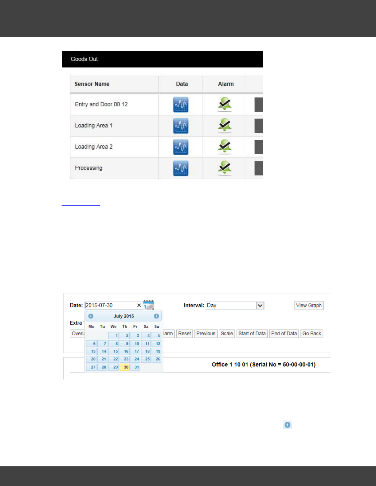
3. For example, moving the pointer down to 'Goods Out' might change the display to
show:
54
Notion Pro © 2017 IMC Group Ltd HP5525 Version 1.2.15
How To . . .
See also:
Viewing Data
4.2.2.2 another Day
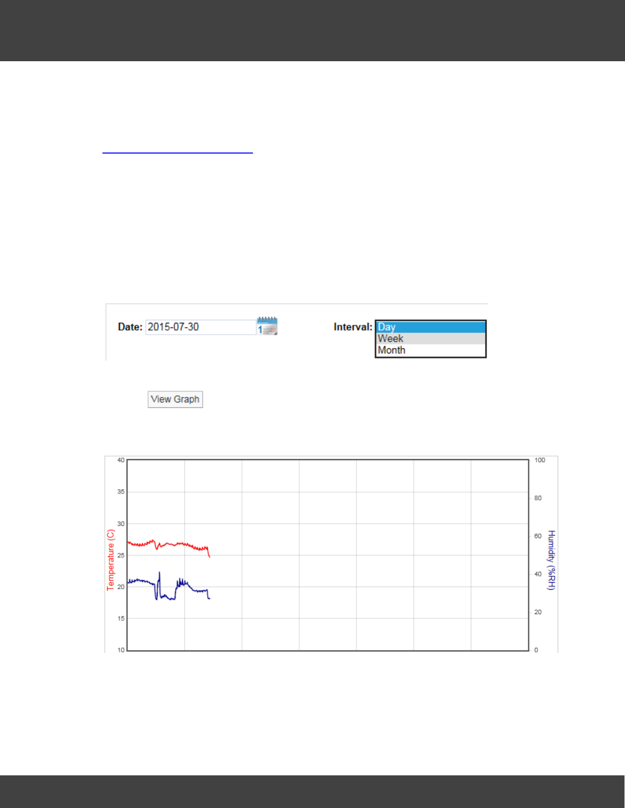
The graphical display shows data from, by default, the current day.
To show data from a day in the past:
1. Click on the calendar icon on the controls above the graphical display:
The current day is highlighted in yellow.
2. Click on the day in the past for which you would like to see the sensor data.
3. The graphical display changes to show data from the selected day.
4. To display data from a month (or a year) in the past, click the arrow at the top of
the calendar until you get to the month of interest, then click on the day of interest.
55
Notion Pro © 2017 IMC Group Ltd HP5525 Version 1.2.15
How To . . .
Obviously you can only get historical data up to the point when the transmitter was
actually installed.
See also:
Operations from the Live View
4.2.2.3 another time interval
By default, sensor data is displayed for the current 24-hour period, but you can change the
display to show data from a wider time interval.
To show data over a different time span:
1. Select a different time interval from the Interval pull-down menu on the controls above
the graphical display:
(if you wish you may also select a different starting date at the same time).
2. Click .
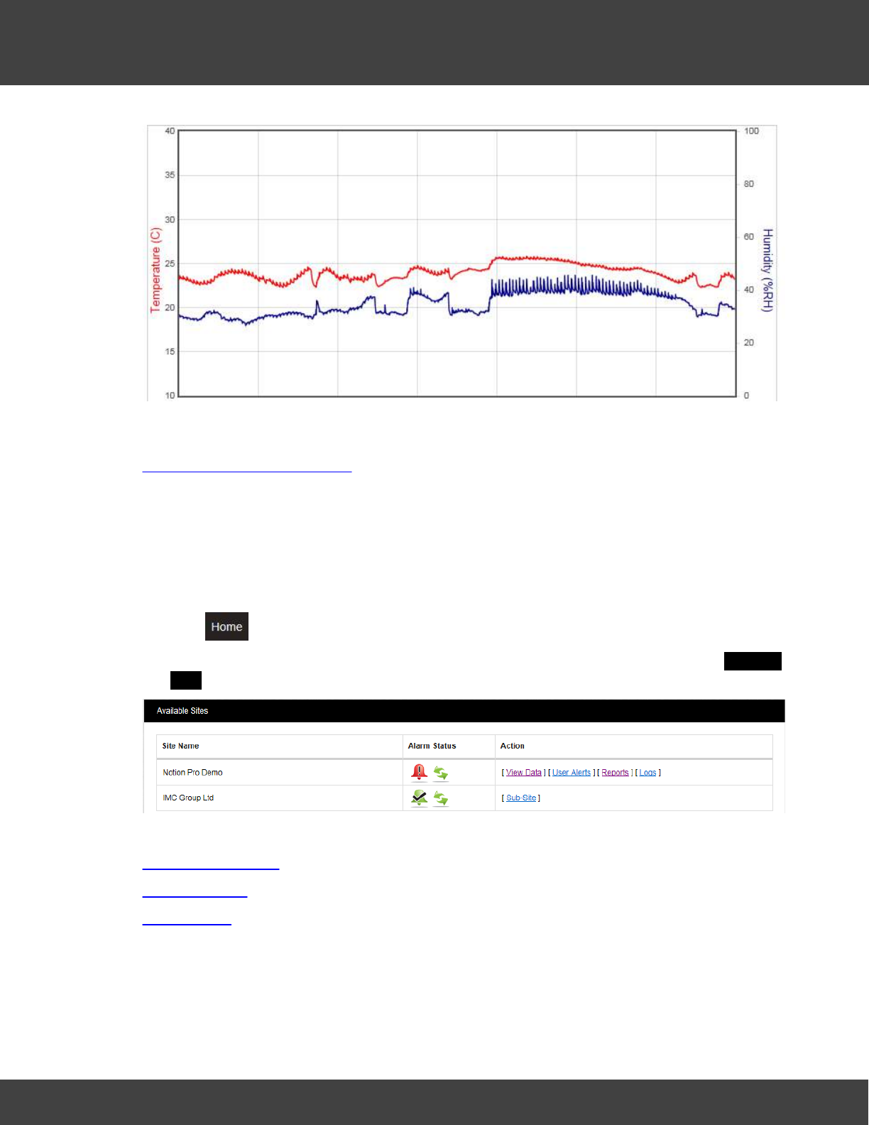
For example, the two displays below show data for a sensor over a one-week period,
followed by a display of data from the same sensor over a one-month period:
56
Notion Pro © 2017 IMC Group Ltd HP5525 Version 1.2.15
How To . . .
See also:
Operations from the Live View
4.2.3 View and Acknowledge Alarms
4.2.3.1 View System Alarm Status Overview
1. Click .
2. View the Alarm and Communication Status of the Sites in your installation in the Available
Sites window.
See also:
Alarm Management
Alarm Statuses
Alarm Status
57
Notion Pro © 2017 IMC Group Ltd HP5525 Version 1.2.15
How To . . .
4.2.3.2 View System Messages
1. From anywhere in Notion Pro, look at the System Message Alert icon at the top of
the screen.
2. To view System Messages, click on the icon.
See also:
System Status Overview
Alarm Statuses
4.2.3.3 Acknowledge Alarms
If the symbol is displayed on the Live View page for a given Site, the associated
transmitter has gone into an Alarm state (for example, a temperature threshold has been
exceeded) and the alarm has not been acknowledged.
To acknowledge an Alarm:
1. Make sure you are in the Live View page for the Zone which contains the sensor of
interest. See another Zone.
2. Click on the symbol for the sensor of interest.
3. On the resulting Acknowledging Alarm for page, enter a suitable message into the User
Actions box, then click Acknowledge.
The symbol changes to to indicate that the alarm has been acknowledged.
4. To reset the alarm, click on the symbol.
See Also:
Acknowledging Alarms
58
Notion Pro © 2017 IMC Group Ltd HP5525 Version 1.2.15
How To . . .
4.3 Create and View Reports
Notion Pro can produce a variety of Reports. These can be tailored to a customer’s
individual specifications. The report will be in .pdf format with the option to export a .csv
data file.
You can create and view:
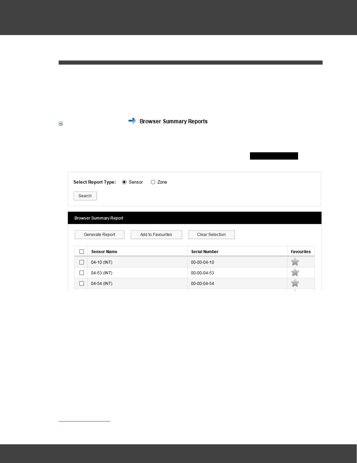
Summary Reports
These can be summaries of data collected by selected sensors or all sensors in a Zone over
the past week.
1. Select Reports>Browser Summary Reports to give the Summary Report dialog
box.
2. To report on selected Sensors:
i. Ensure that the Sensor option button is selected.
ii. Select the sensors of interest from the Sensor Name list.
iii. Select Generate Report.
3. To report on a Zone:
i. Ensure that the Zone option button is selected.
ii. Select Search.
iii. Select the Zone of interest from the Zone Name list.
iv.Select Generate Report.
See also:
Summary Reports
59
Notion Pro © 2017 IMC Group Ltd HP5525 Version 1.2.15
How To . . .
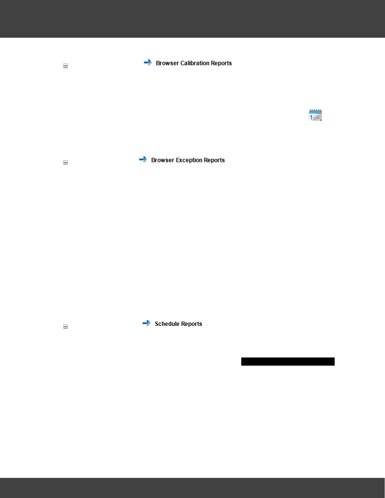
Calibration Reports
A simple report of all sensors that need calibrating on a given date.
1. Select Reports>Browser Calibration Reports.
2. By default, a Report will be generated for all sensors which need to be calibrated one
month from today's date. If you wish to select a different due date click and
select the required date. Select the 'Include Out of Service Sensors' tick box if
required. Click Search to generate the Report.
Exception Reports
Reports of ongoing alarm conditions, by Sensor or by Zone.
1. Select Reports>Browser Exception Reports.
2. To report on selected Sensors:
i. Ensure that the Sensor option button is selected.
ii. Select the sensors of interest from the Sensor Name list.
iii. Select Generate Report.
3. To report on a Zone:
i. Ensure that the Zone option button is selected.
ii. Select Search.
iii. Select the Zone of interest from the Zone Name list.
iv.Select Generate Report.
Scheduled Reports
Reports of a variety of types which start and end at predefined dates/times and run at
predefined intervals.
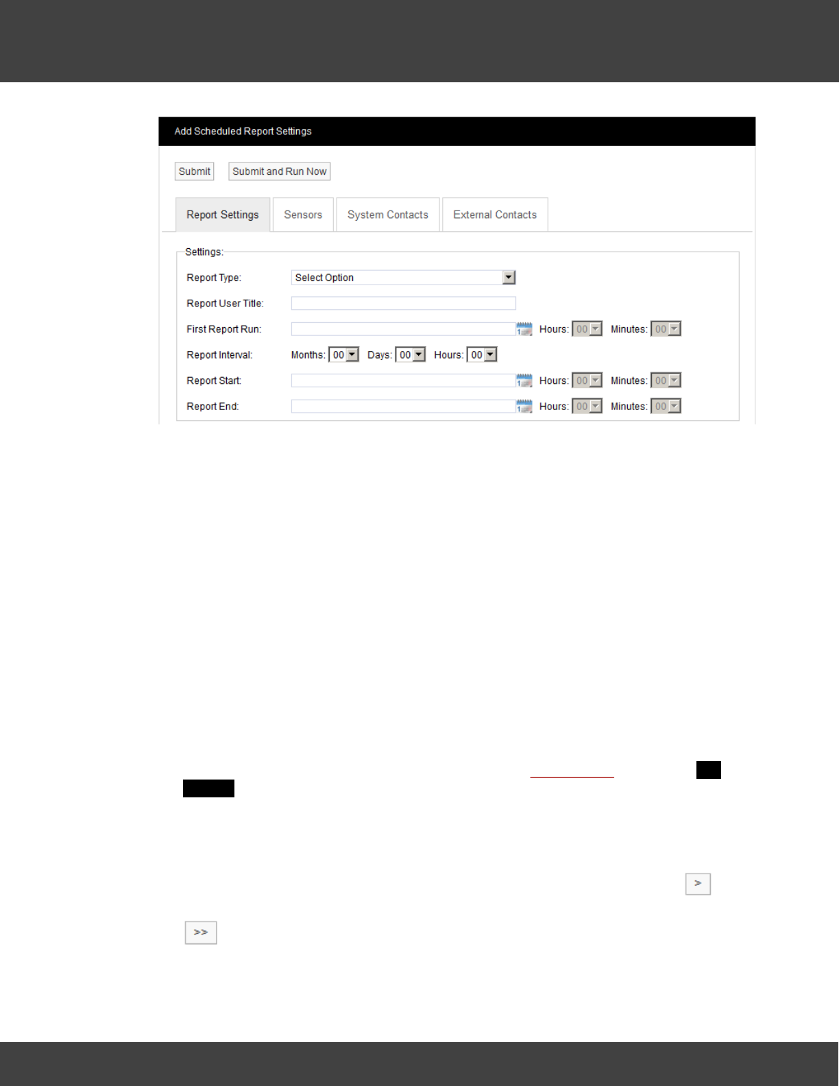
1. Select Reports>Scheduled Reports to give the Add Scheduled Report Settings
dialog box.
60
Notion Pro © 2017 IMC Group Ltd HP5525 Version 1.2.15
How To . . .
2. Select the required Scheduled Report Type from the Report Type: pull-down list.
3. Enter a suitable title for the Report in the Report User Title: box.
4. Select a date and time for the first Report run using the First Report Run: controls.
This should be later today or any time in the future.
5. Specify a Report Interval if required. This is the length of time between repeated
runs of the Report. For example an interval of one day would give daily Reports. You
don’t have to specify a Report Interval, this would give a ‘one off’ Report.
6. Use the Report Start: and Report End: controls to specify the time span for the
Report. This would typically be dates in the past, but could be dates in the future
(although if, for example you specified a start date one week in the future and end
date two weeks in the future you would have to wait 2 weeks before you saw a
Report).
Note: you should set an Interval, with no Report Start or Report End time, or a
Report Start and Report End time, (but no Interval).
7. Having set up the Report dates, we now need to specify the Sensor data that we
wish to report on. Click the Sensors tab, then click Add Sensors to give the Add
Sensors dialog box.
8. Select the Zone that contains the sensors you wish to report on from the Zone
Name pull-down list. The Source List becomes populated with the sensors in the
selected Zone.
9. Select a sensor in the Source List that you wish to report on, and select to
transfer it to the Destination List. To transfer all sensors in a single operation click
.
10. When satisfied with your selections, select Submit.
61
Notion Pro © 2017 IMC Group Ltd HP5525 Version 1.2.15
How To . . .
11. Now we need to specify a list of Users (System Contacts) that the Report will be
emailed to. Click the System Contacts tab, then click Add Sensors to give the Add
Contacts dialog box.
12. Populate the Destination List for System Contacts using the same methods that
you used to populate the Destination List for Sensors (see step 9 above). When
satisfied with your selections click Submit.
13. If any External Contacts have been set up and you wish to send the Report to
them, select the External Contacts tab and populate and Submit it in the same
way as for System Contacts.
14. When satisfied with all of your Report Settings, select Submit or Submit and Run
Now under the Add Scheduled Report Settings banner. Submit and Run Now
button is used to generate reports immediately; however some delay can be
expected if a large report is submitted.
The Scheduled Report you have defined will now be added to the View Scheduled Reports
window.
See also:
Setting Up and Running Reports
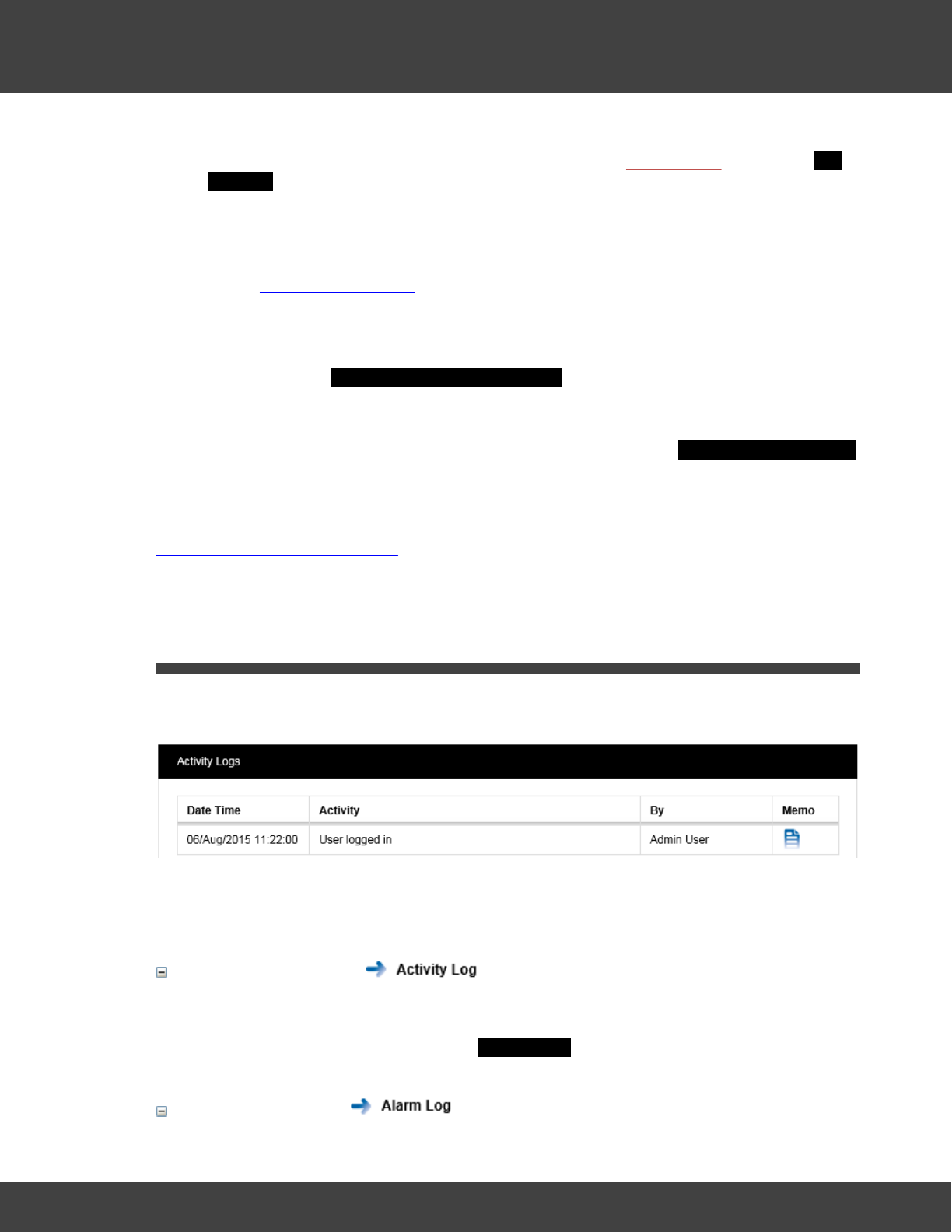
4.4 View System Logs
Notion Pro has a series of System Logs for keeping track of critical events such as system
activity, alarm activity and SMS activity.
You can:
View the Activity Log
Logs user activity.
Select Logs>Activity Log to give the Activity Logs dialog box.
View the Alarm Log

Reference Section
64
Notion Pro © 2017 IMC Group Ltd HP5525 Version 1.2.15
Reference Section
5Reference Section
See below for a list of information topics.
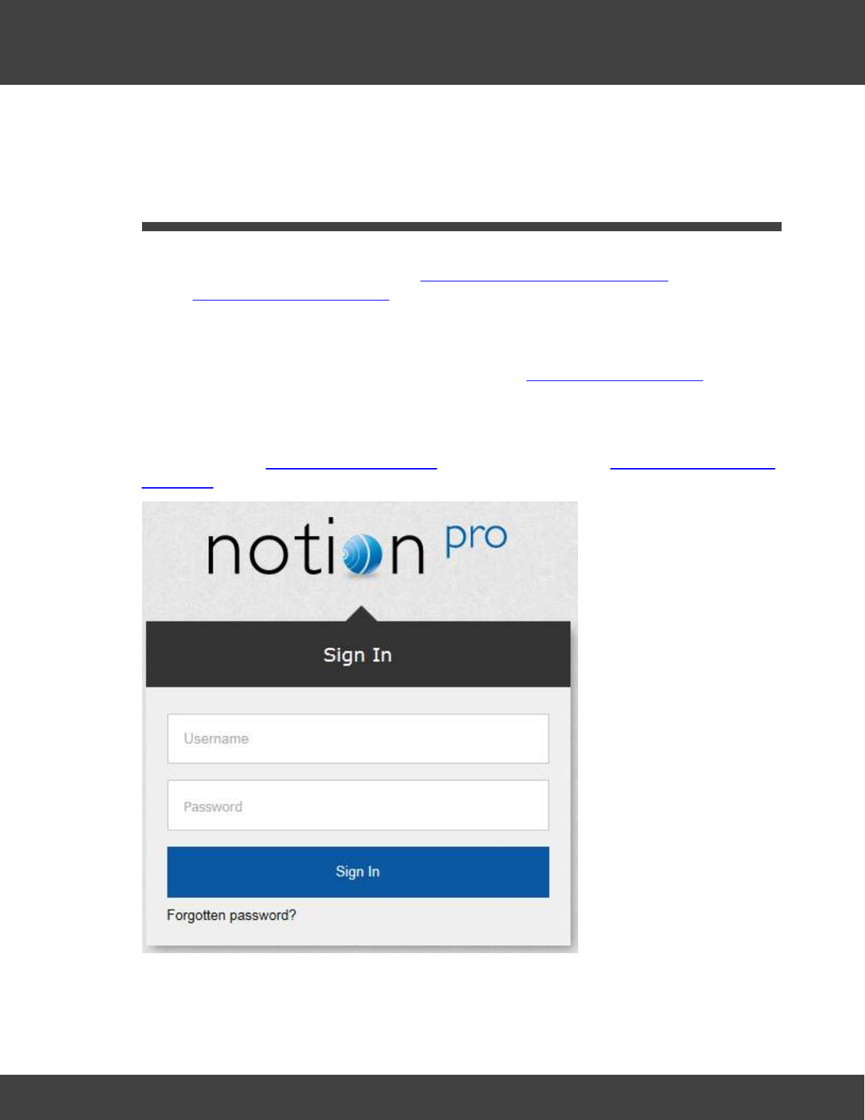
5.1 Signing In
Note: If you are NOT a System Administrator, you will be unable to access the Notion Pro
facilities detailed in this topic, the Setting Up Users, Sites and Devices topics, and the
Setting Up the Sensor Model topics.
To view the Notion Pro website, you will need to open a browser and navigate to the Notion
Pro site.
If you are working on the Notion Pro Server itself, type http://localhost/NotionPro on to the
Browser’s address field.
If you are working on a another computer or device, you will need to use the URL supplied
by your System Administrator or IT Support provider to reach the Notion Pro server. This
may be similar to \\ServerName\NotionPro for a LAN connection or www.mycompany.com/
Notion Pro for an internet connection.
Once you have navigated to the correct URL, the login screen will be displayed, as above.
As you are setting up the System immediately after installation, you need to login as the
65
Notion Pro © 2017 IMC Group Ltd HP5525 Version 1.2.15
Reference Section
System Administration User:
Username: Admin User
Password: Admin
Enter your username and password to login, then click Sign In. Passwords are case
sensitive.
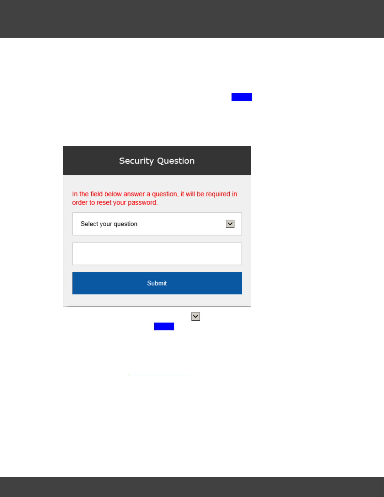
As this is the first time you have logged in, you must supply the answer to a security
question, so if you forget your password in the future you can retrieve it using a procedure
which includes supplying the answer to your security question. See below:
Choose your security question by clicking and choosing from the list. Type the answer
into the box below, then click Submit. You will now be returned to the login screen, where
you will again need to enter your username and password.
The Security Question screen is only shown when a user logs in for the first time; it will not
show when you login as the Admin User again.
Note: When you are editing users' details, you should change the default Admin User
password so that it is secure.
5.1.1 View Archived Database
For detailed information about the Notion Pro Archive / Backup system, see the IceSpy
Notion Pro Archive/Backup Manual, doc no IM5549.
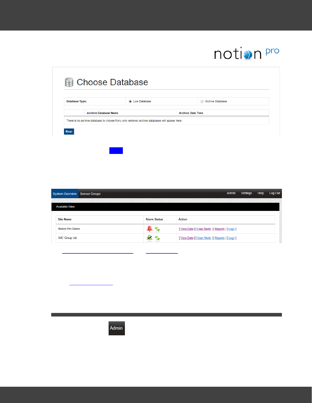
66
Notion Pro © 2017 IMC Group Ltd HP5525 Version 1.2.15
Reference Section
To access Archived data, select Archive Database, select the required Archive Database
from the list, then click Next.
5.1.2 View Live Database
To access the live Notion Pro system, make sure Live Database is selected and click Next
to give the System Overview, see below for an example.
See Setting Up the Sensor Model and Viewing Data for more details of the System Overview
display and viewing Live Data.
Note: You will only see the Available Sites view if your installation has more than one Site.
For a one-Site installation, clicking Next will take you straight to the Live View, see
Viewing Live Data.
5.2 Setting Up Users, Sites and Devices
The options under the menu enable System Administrators to set up Notion Pro for
use.
5.2.1 User Management
Note: The functionality described in this Section only applies to System Administrators or
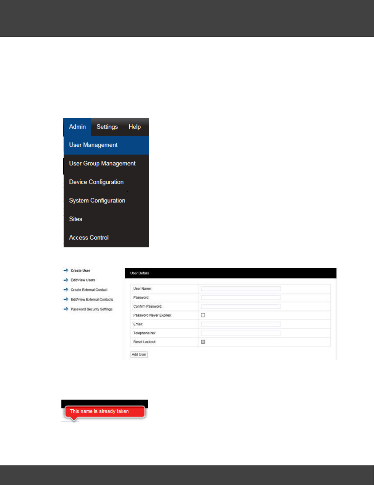
67
Notion Pro © 2017 IMC Group Ltd HP5525 Version 1.2.15
Reference Section
Users who have been given System Administrator access rights. The Admin User is
created automatically when Notion Pro is installed. The Admin User cannot be
deleted.
User Management allows you to add Users, edit Users add External Contacts and edit
External Contacts.
Adding and Editing Users
Select Admin then User Management from the drop down
menu to access the User Management section.
The Admin menu is located at the right hand side of the top
menu bar.
After selecting User Management a new window appears see
below.
Add User Name
In the dialog box above enter a new User Name. If the user name is already taken the
following message will be displayed.
Select another User Name until the following message is displayed:
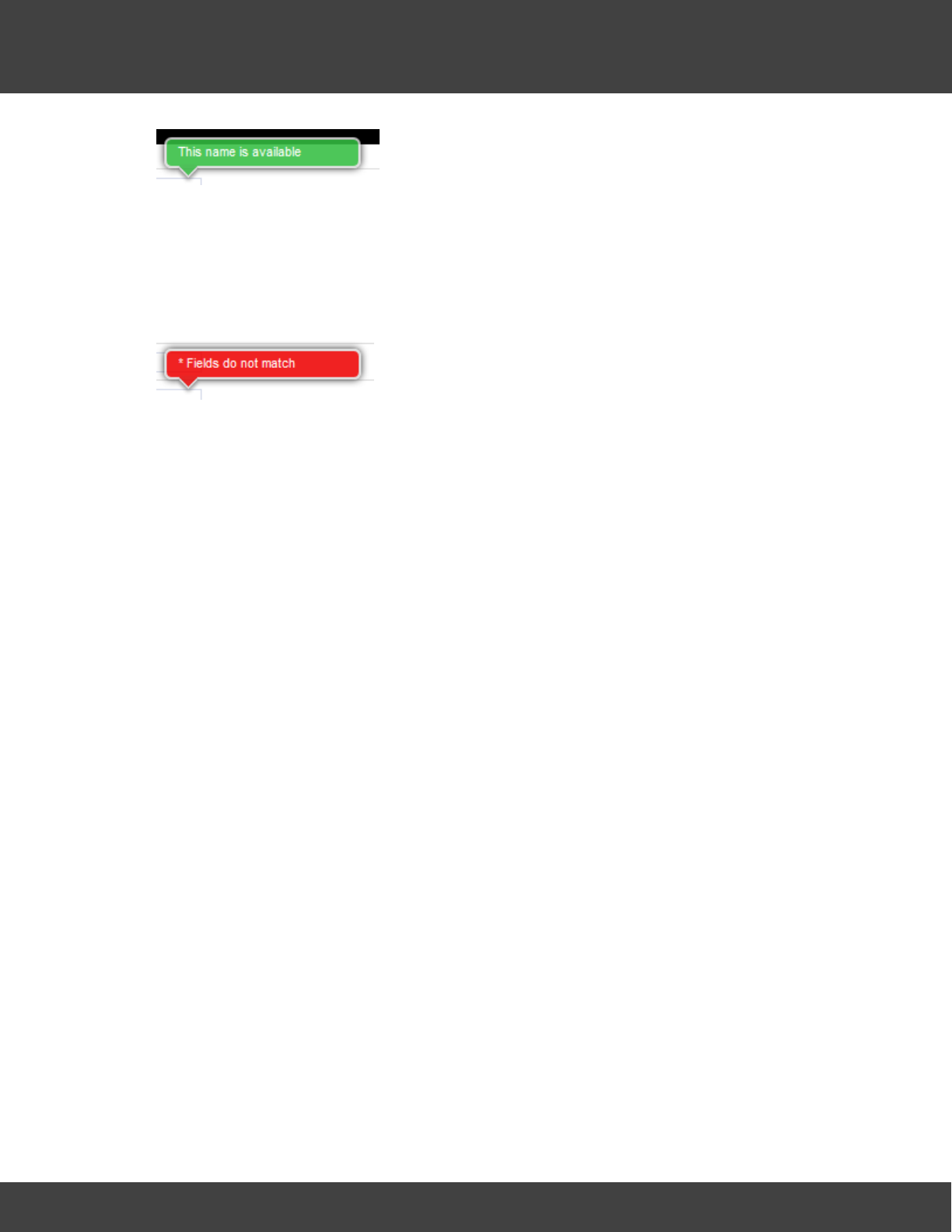
68
Notion Pro © 2017 IMC Group Ltd HP5525 Version 1.2.15
Reference Section
Add Password
Enter a password into the Password field, now re-enter your password into the Confirm
Password field. It is not recommended to cut and paste the password as this would copy a
mistake to the Confirm Password field. If when typing your password into the Confirm
Password field you make a mistake, the following message will be displayed.
If you have re-typed your password correctly then you will be able to proceed to the next
step.
By default, Notion Pro requires passwords to be at least four characters long. The
Administrator will not be able to set a minimum password length of less than four
characters. This is configurable by the Administrator. The User ID and password cannot be
the same.
Administrators may also require that user passwords have an alphanumeric and mixed case.
In this case, passwords must have numeric characters, upper and lower case letters.
Note: It is recommended that a password be at least eight characters in length and
contain at least one number, one letter, one uppercase letter.
Password Never Expires
By default user passwords are set to expire in 90 days, this is selectable by the
Administrator.
Password Expiry does NOT apply to the Admin User password, which is always set to never
expire.
Email:
This field allows you to enter your email address. This is used to receive the following:
·email alerts generated from the system
·email reports.
·password reminders.
Telephone No:
This field allows you to enter your mobile phone number. This is used to receive SMS text
alerts generated from the system.
The number should be entered in the following format:
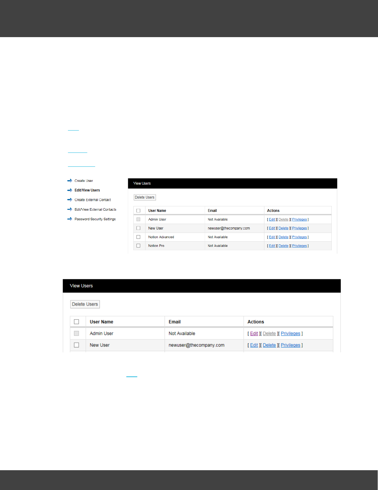
69
Notion Pro © 2017 IMC Group Ltd HP5525 Version 1.2.15
Reference Section
+44 123 987654
When you are happy that all details are correct, click the Add User button.
Edit/View Users
Edit/View Users allows you to edit existing user’s details. The following functions are
available:
·Edit allows passwords to be changed along with email address, phone number and
calibration technician status
·Delete allows single or multiple users to be deleted
·Privileges allows users to be set with viewing rights.
To edit new user, select Edit/View Users. A new window opens, see below.
Edit
To edit a user select Edit. After selecting Edit a new window opens, see below.
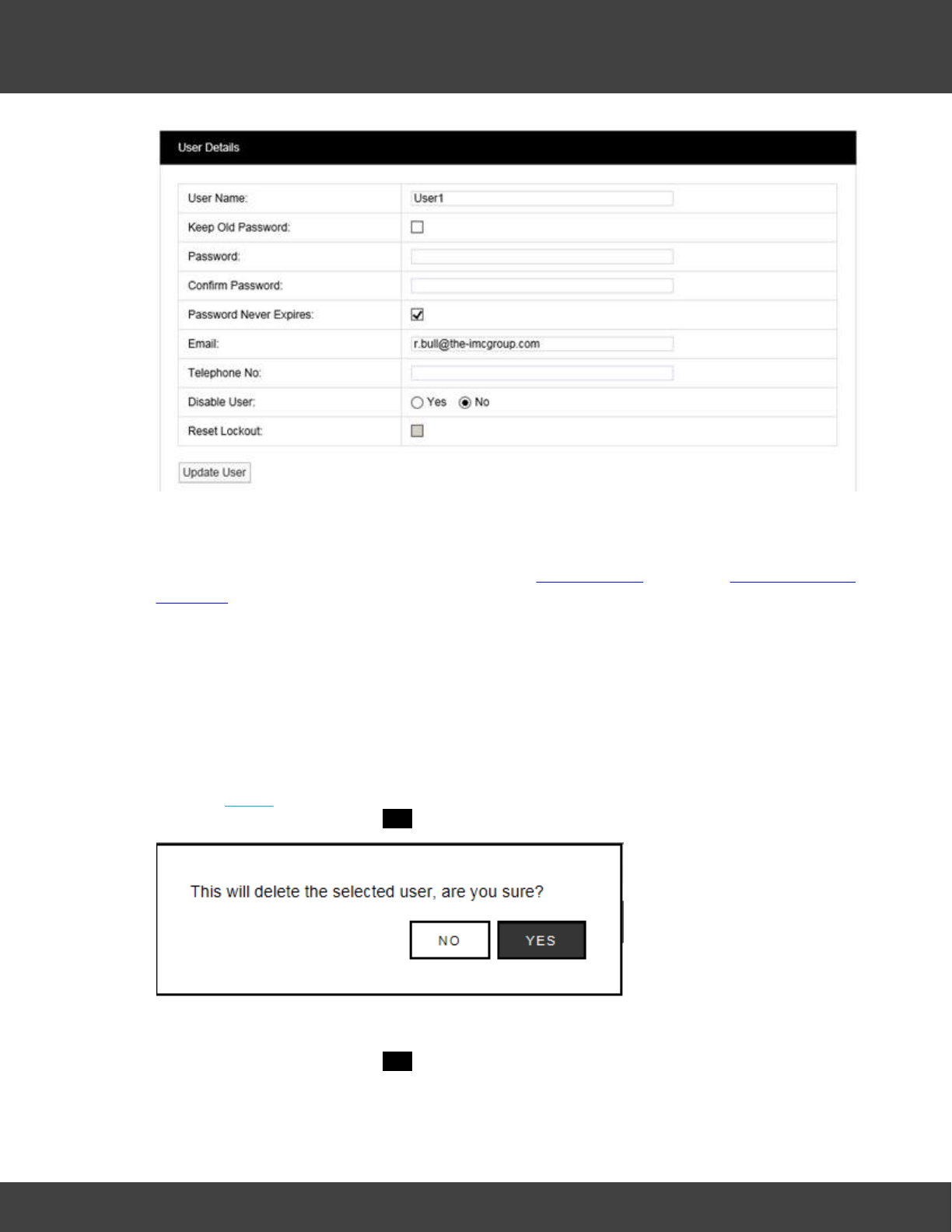
70
Notion Pro © 2017 IMC Group Ltd HP5525 Version 1.2.15
Reference Section
In this screen you can change the User’s email address, mobile phone number or calibration
technician status. If you wish to update the User without changing your password tick Keep
Old Password and the existing password will be populated in the password dialog boxes. If
you wish to change your password follow steps in Add Password. (See also Change a User's
Password.)
Reset Lockout
Locked out users can be reset from this screen, by selecting Reset Lockout.
When you are happy that all details are correct, click the Update User button.
Delete User
There are three methods for deleting users:
1. Select Delete. This will delete the record selected, once you are happy with your selection
confirm delete by selecting YES on the warning dialog box (see below.
2. If more than one user is to be deleted select the tick box to the left of the name, tick all
users to be deleted. Once you are happy with your selections click Delete Users select
confirm delete by selecting YES on the warning dialog box.
3. By clicking the tick box next to User Name all users will be deleted. WARNING, this will
select all users for deletion. Once you are absolutely sure you want to delete all users
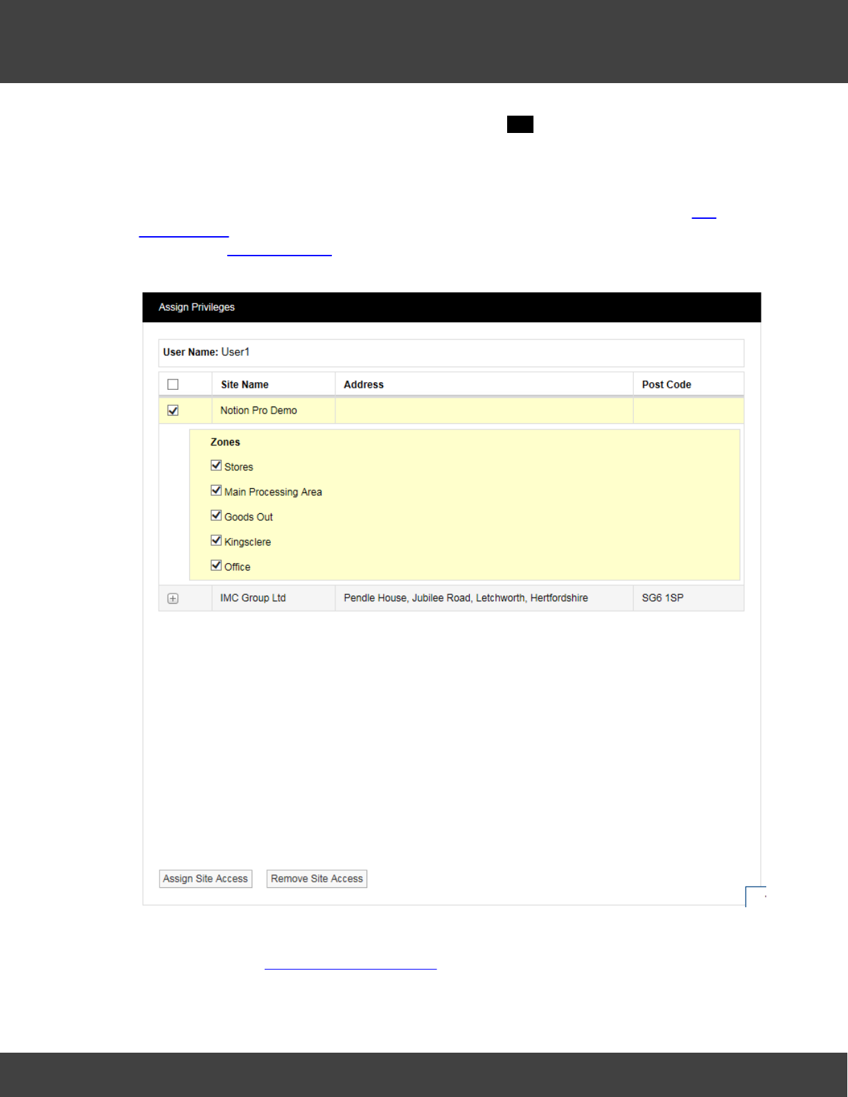
71
Notion Pro © 2017 IMC Group Ltd HP5525 Version 1.2.15
Reference Section
click Delete Users and confirm delete by selecting YES on the warning dialog box.
WARNING: Deleting users cannot be undone.
User Privileges
This allows individual users to be assigned viewing rights to Sites and Zones. (See Site
Management for more information on Sites and Zones.) Click on Privileges in the View User
window (see Edit/View Users) for the User that you wish to assign viewing rights to. This
gives the Assign Privileges dialogue box (see below).
In the example above, User1 has been pre-allocated with viewing access to the Notion Pro
Demo Site and the listed Zones. Click Assign Site Access or Remove Site Access as
required. See also User Group Management.
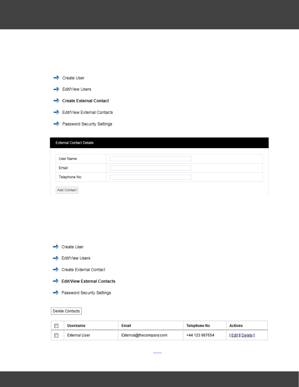
72
Notion Pro © 2017 IMC Group Ltd HP5525 Version 1.2.15
Reference Section
Create External Contacts
External contacts are used when there is a requirement to email reports or send SMS
alarms to people who are not Notion Pro users.
To create external contacts, select Create External
Contact.
After selecting Create External Contact a new window opens,
see below.
Enter User Name, Email and Telephone No for an external user. There is no requirement
for a password as these users do not have access to Notion Pro.
Edit/View External Contacts
To Edit/View external contacts, select Edit/View External
Contacts.
After selecting Edit/View External Contacts a new window
opens.
To edit external user details follow steps at Edit, to delete external users follow the steps in
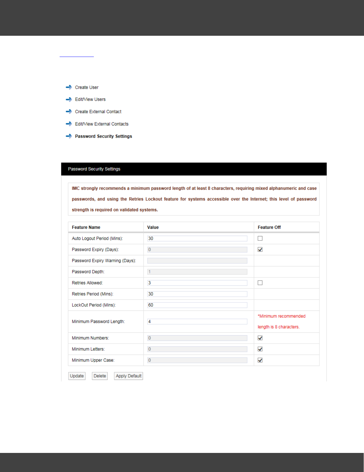
73
Notion Pro © 2017 IMC Group Ltd HP5525 Version 1.2.15
Reference Section
Delete User.
Password Security Settings
To Edit/View Password Security Settings, select Password
Security Settings. Once selected, the Password Security
Settings window will be shown see below.
Figure
The Password Security Settings window is used to set the system’s login security
features. Login security features apply globally to all logins, with some exceptions for the
Admin User account, as detailed below. Individual features can be disabled by selecting the
associated Feature Off tick box. Clicking Apply Default will return Password Security

74
Notion Pro © 2017 IMC Group Ltd HP5525 Version 1.2.15
Reference Section
features to the default settings. click Update to apply any changes made.
Auto Logout Period (Mins)
If a login session is left unattended, then the system will log the user off after the Auto
Logout period. The auto logout period can be set by the Administrator.
When Auto Logout activates, the browser will continue showing the last screen actioned by
the user, and if on the Live View, data values will continue to update on the screen.
However, when the user tries change window or enter a value, then the browser will show
the Login screen and require the user to log back into the system.
The Auto Logout Period can be set between 5 and 60 minutes, the default period is 30
minutes.
Password Expiry
Passwords will automatically expire, and need to be changed, after the Password Expiry
time. By default user passwords are set to expire in 90 days, this is selectable by the
Administrator. Password Expiry does NOT apply to the Admin User password, which is
always set to never expire.
Users are warned on login within 10 days of expiry, and given the option to type in a new
password. This can be done any time between the first warning and expiry. The warning
time is settable by the Administrator. This will be a countdown warning and will decrease as
the expiry deadline approaches.
Once a password has expired no further access will be allowed for that user until they enter
their expired password at which point the system will force a change before any further
progress can be made.
Password Depth
This option is NOT available on the standard version of Notion Pro.
The Password Depth sets the number of previous passwords that cannot be immediately
reused by a user. A password depth can be set globally, between 1 and 10.
Retries Allowed
This is the number of failed login attempts allowed for a username, within the Retries
Period, before the user is locked out. Locked out users are informed of their locked out
status, when they try to login.
Lockout Period is the time that a user will be locked out after the Retries limit is exceeded.
By default users will be locked out for 60 minutes after three consecutive failed password
login attempts within a 30 minute period. Where a lockout occurs, the user will be informed
of the lockout period by a message on the browser, and the lockout will be recorded in the
activity log.
The number of Retries Allowed can be up to 10. The Lockout Period can be up to 1440
minutes and the Retries Period can be between 10 and 1440 minutes. The Admin User is
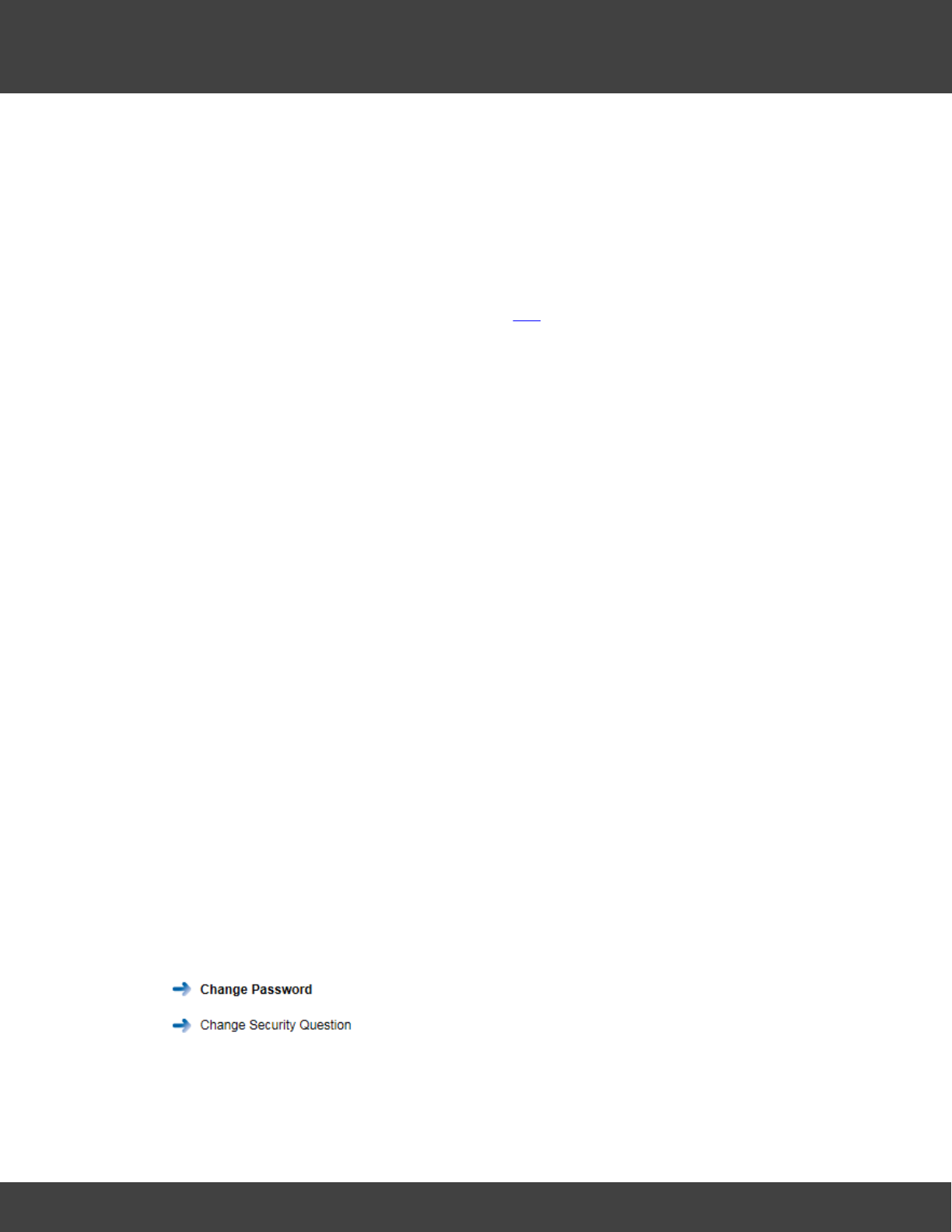
75
Notion Pro © 2017 IMC Group Ltd HP5525 Version 1.2.15
Reference Section
never locked out.
A lockout value of 0 will lock out users until reset by the Administrator. Any Administrator
lockout will be for 30 minutes, (this prevents the Administrator becoming permanently locked
out).
A Reset Lockout tick box is available on the User Details screen. This control will
normally be greyed out, and will only become active when the user is currently locked out.
This control is only accessible by an Administrator. Administrators can reset a locked out
user from the Edit/View Users window, see Edit.
Username Reuse
Deleted usernames cannot be reused for the period of time specified by Username
Reuse. If an Administrator types a Reuse blocked username into the User Details
screen, a warning will be displayed. By default, Username Reuse checking is disabled.
Minimum Password Length
By default, Notion Pro will require passwords to be at least four characters long, the
Administrator will not be able to set a password length of less than four characters. This is
configurable by the Administrator. The User ID and password cannot be the same.
Accepted Value Ranges
The list below details the setting ranges for each option:
Auto Logout – 5 to 60 minutes.
Password Expiry – 30 to 730 days.
Retries Allowed – 1 to 10 attempts.
Lockout Period – 0 to 1440 minutes; 0 will lockout users until reset by the Administrator.
Retries Period – 10 to 1440 minutes.
Password depth – 1 to 10; not available on the standard version of Notion Pro.
Minimum Password Length – 8 to 50 characters.
Minimum Numbers, Minimum Letters, and Minimum Upper Case – 1 to 50, these values are
consistency checked, against minimum length and each other.
Changing the Password
To change your password select Settings>Account
Settings then Change Password to give the Change
Password dialogue box. See below.
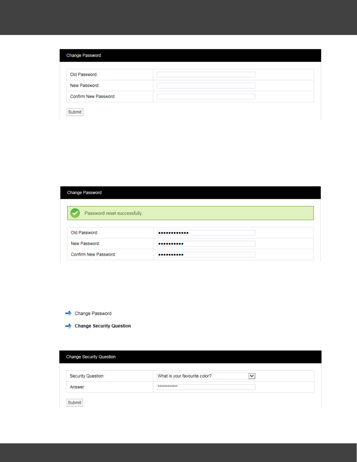
76
Notion Pro © 2017 IMC Group Ltd HP5525 Version 1.2.15
Reference Section
Enter the old password in the Old Password field. Enter the new password in the New
Password field, enter it again in the Confirm New Password field.
Note: It is recommended that a password be at least eight characters in length and
contain at least one number, one letter, one uppercase letter.
Click Submit. The message shown below will be displayed to confirm a successful password
reset.
Changing your Security Question
You will need to know the answer to your security question if you have forgotten your
password and you have to click on the Forgotten password? Link on the Sign In screen.
To change your security question select Settings>Account
Settings then Change Security Question to give the
Change Security Question dialogue box. See below.
Select your desired question from the Security Question pull-down list, the enter the answer
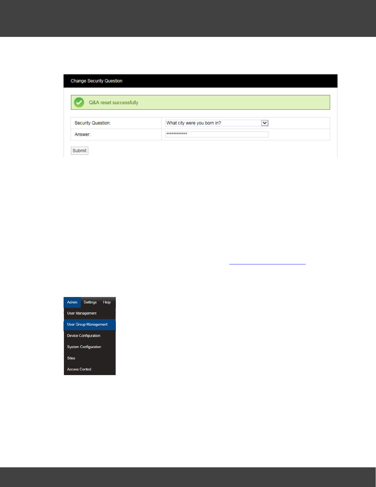
77
Notion Pro © 2017 IMC Group Ltd HP5525 Version 1.2.15
Reference Section
into the Answer field, then click Submit. Click Submit. The message shown below will be
displayed to confirm a successful password reset.
5.2.2 User Group Management
User Group Management
This section describes how User Groups are created and used. User Groups allow viewing
Privileges to be set for a group, Users added to that group inherit the viewing Privileges
associated with that group. Any previous viewing Privileges assigned to an individual user will
be overridden by the viewing Privileges associated with that group.
To learn about setting Privileges for individual users see User Group Management. Privileges
are the viewing rights that allow a user to see Sites and Zones. Through Privileges a user
can be restricted to the number of Zones they can see. This is especially useful on very
large systems.
Select Admin>User Group Management from the drop down menu
to access the User Group Management section.
After selecting User Group Management a new window appears, see
below.
Create User Groups
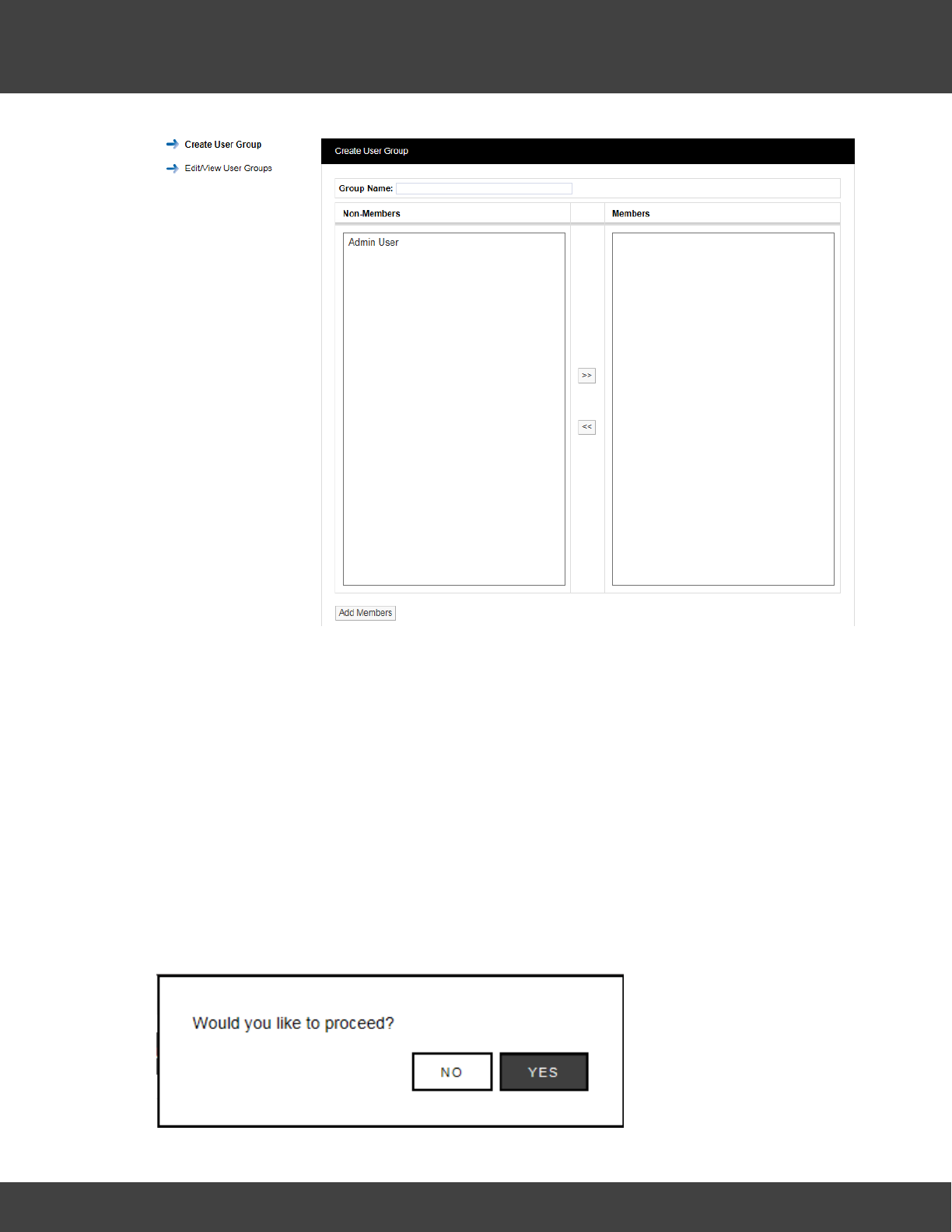
78
Notion Pro © 2017 IMC Group Ltd HP5525 Version 1.2.15
Reference Section
To create a User Group, enter a name for the User Group, see examples below:
·T+RH Sensors - for a small Site this could be used to allow access to all of the
temperature and humidity sensors.
·T+RH Sensors 1st Floor - for a larger site this could be used to allow access to all of
the temperature and humidity sensors on one floor.
Select the Users that you would like to add to the group. All users that have not already
been associated with a group will be shown in the left column. To select more than one user
hold the Ctrl key and select the required users. Once you are happy with the selected users
click the double left arrows located between the columns, this will move the users to the
right column.
Users can be de-selected by selecting them in the right column and clicking the double left
arrows. When you are happy with your selection, click on Add Members. You will be asked
if you would like to proceed, see below.
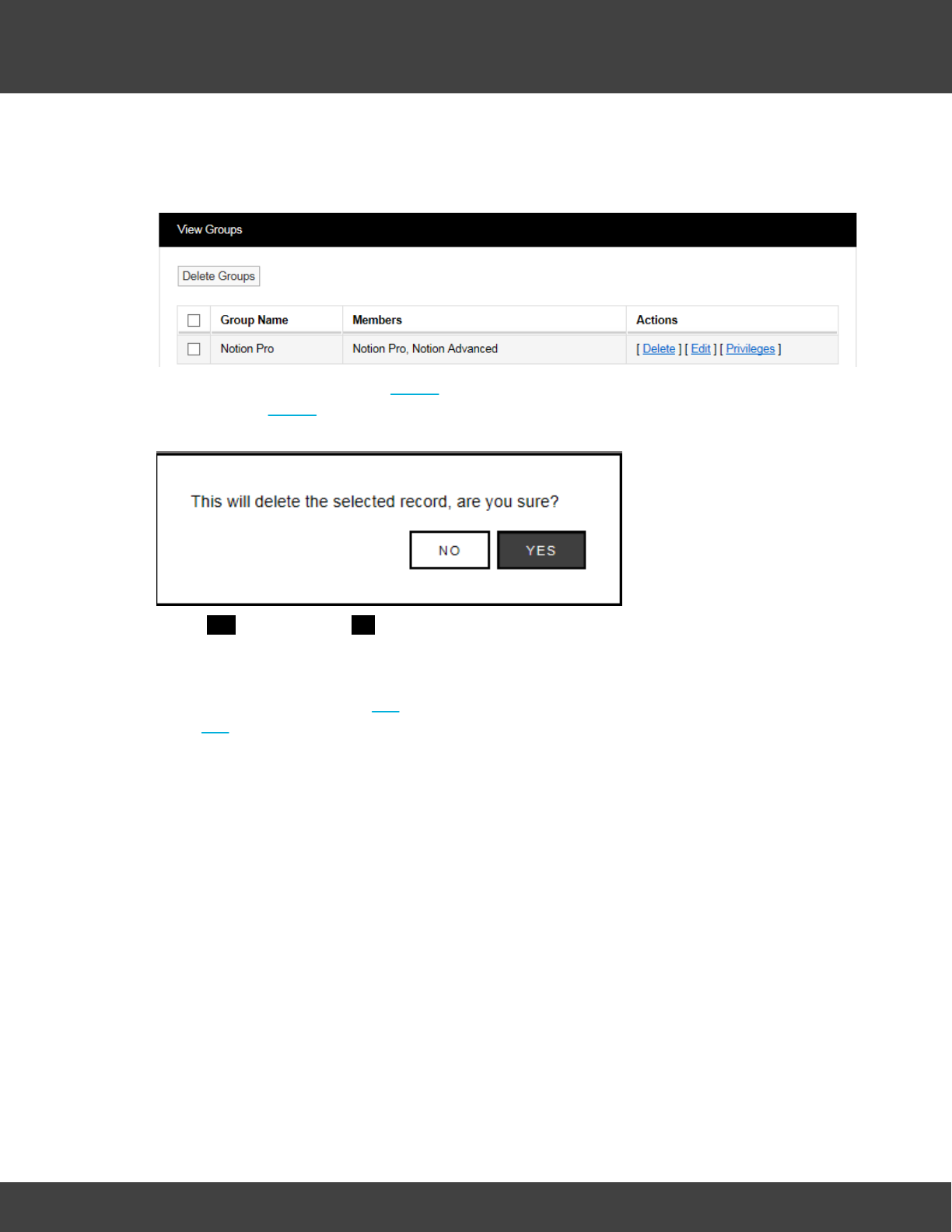
79
Notion Pro © 2017 IMC Group Ltd HP5525 Version 1.2.15
Reference Section
Select YES to proceed or NO to cancel.
Delete User Group
To delete a User Group select Delete in the line corresponding to the User Group to be
deleted. Once Delete has been selected you will be asked if you would like to proceed, see
below.
Select YES to proceed or NO to abort.
Edit User Group
To Edit a User Group select Edit in the line corresponding to the User Group to be edited.
Once Edit has been selected the Edit User Groups window will appear, see below.
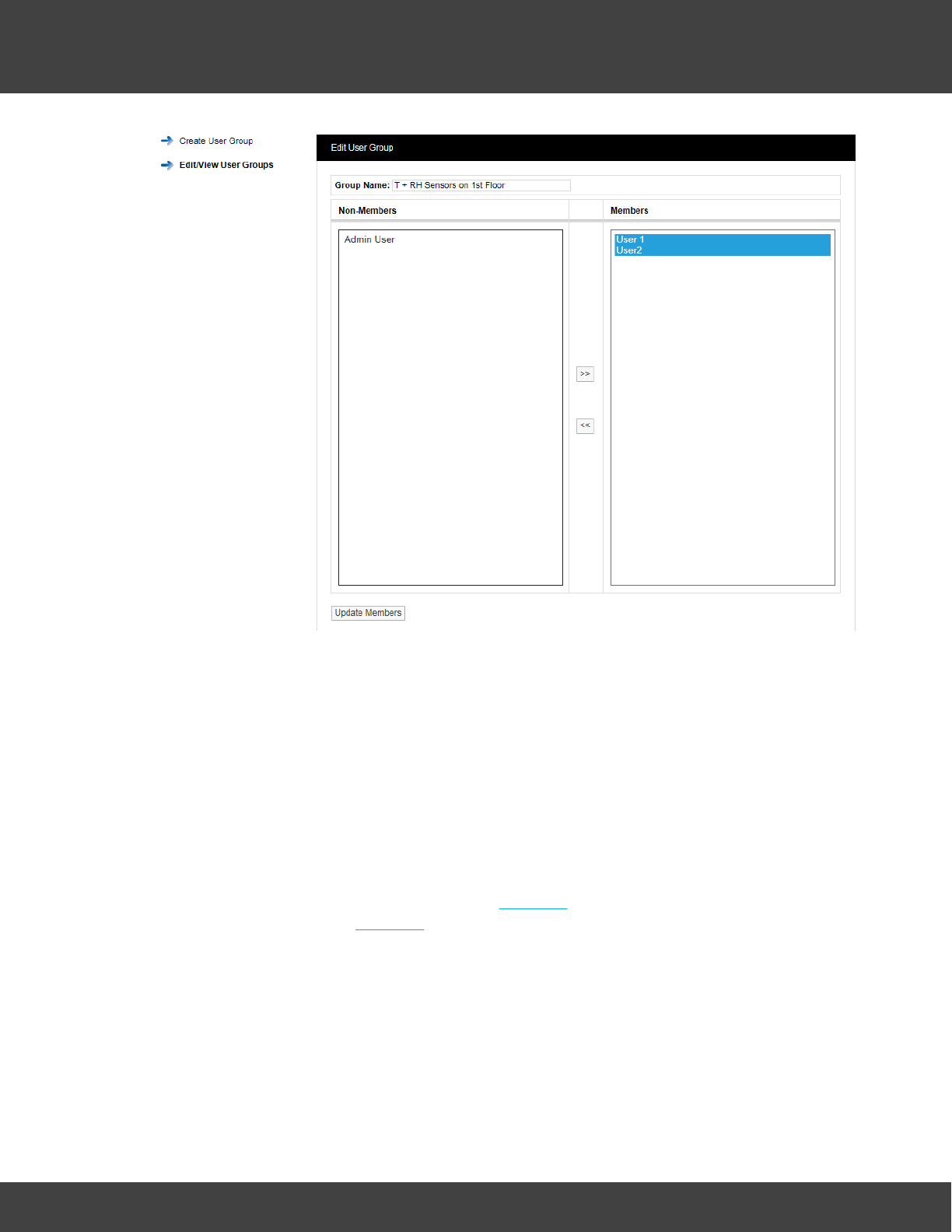
80
Notion Pro © 2017 IMC Group Ltd HP5525 Version 1.2.15
Reference Section
Users can be removed from the User Group or added. To remove Users highlight them in
the right column and click the double left arrows. To add Users highlight them in the left
column and click the double right arrows.
When happy with your selections click Update Members. You cannott remove all the
members from a group you must always have to have at least one member. If you want
to remove all the members then the User Group needs to be deleted.
When a User is removed from a User Group that User will require Privileges adding, see
section 2.1.9 to add Privileges.
User Group Privileges
To set the Privileges for a User Group select Privileges in the line corresponding to the User
Group to be edited. Once Privileges has been selected the Assign Privileges window will
appear, see below.
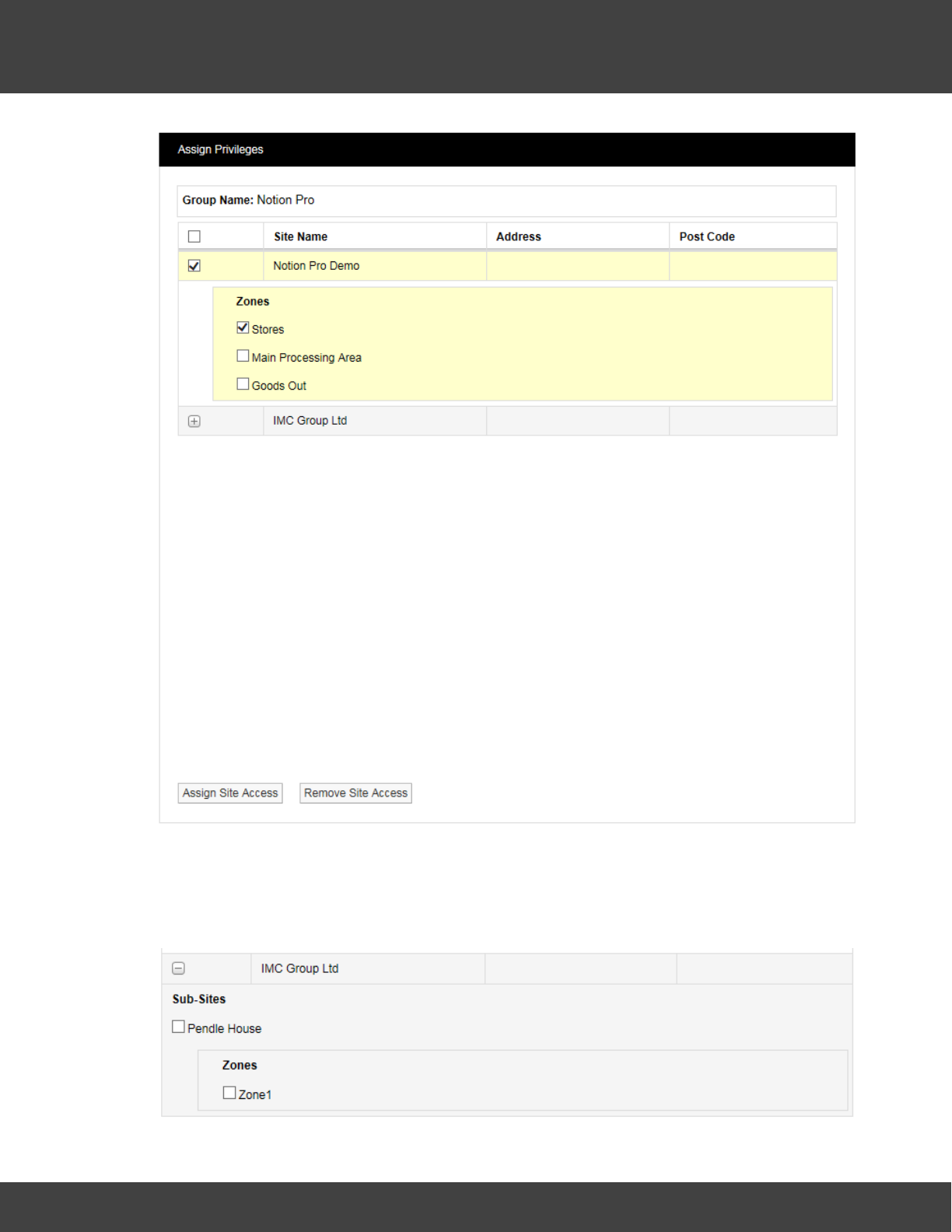
81
Notion Pro © 2017 IMC Group Ltd HP5525 Version 1.2.15
Reference Section
All Sites that have been added to Notion Pro will be visible in the Assign Privileges window.
Sites with an empty tick box are top level Sites with no Sub Sites associated. Sites with a +
symbol have Sub-Sites associated, see IMC Group Ltd above.
Selecting the + symbol will reveal the Sub Site details, see below.
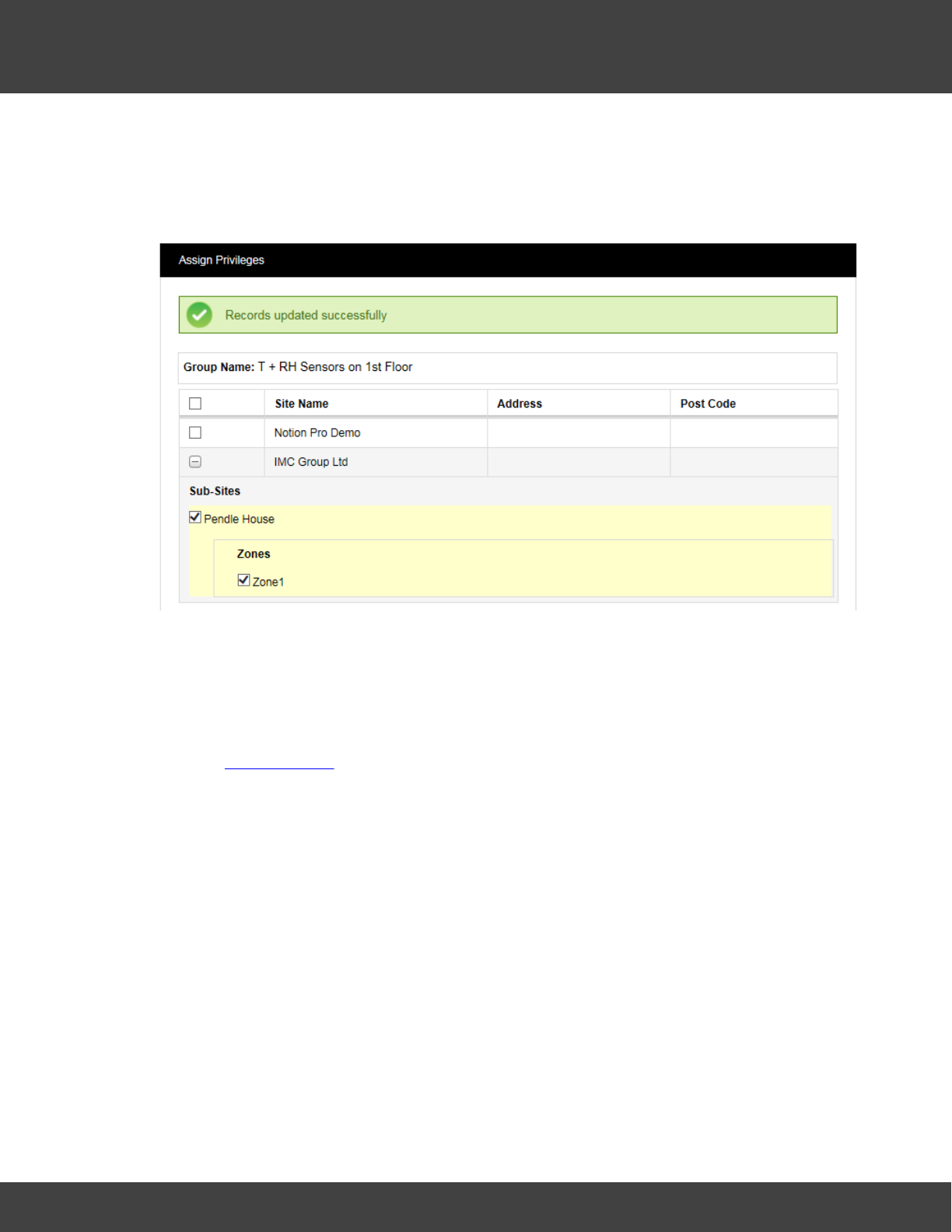
82
Notion Pro © 2017 IMC Group Ltd HP5525 Version 1.2.15
Reference Section
To allow the members of User Group T + RH sensors 1st floor to view the sensors from
the IMC Group Pendle House subsite select the tick box next to Pendle House. This will now
allow all Users added to this group to be able to see those sensors only.
When you are happy with your selections click on Assign Site Access, see below.
To remove access the process is the reverse of the above. When happy with your
selections click on Remove Site Access.
Some sites will have more Zones and sensor types than others. However, the process for
allocating Privileges is the same. Depending on what the System Administrator wants an
individual user to see as many or as few sensors or Zones can be selected.
See also User Privileges for more information on setting Privileges.
5.2.3 Access Control
This topic describes how users are granted Permissions. Permissions are system access
rights such as Edit, Delete etc.
Notion Pro allows the creation of Roles which are assigned with access permissions. Users
are added to Roles and inherit the permissions assigned to the Role thus avoiding the
repetitious and error-prone task of adding multiple individual users.
Permissions Overview
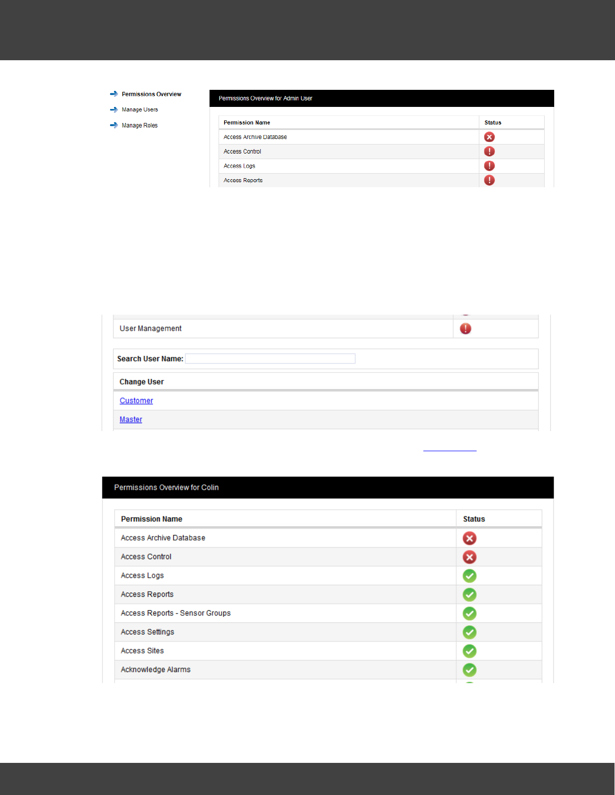
83
Notion Pro © 2017 IMC Group Ltd HP5525 Version 1.2.15
Reference Section
The menu on the right above gives access to the different sections of Access Control, the
list on the left above is the Permissions Overview for the Admin User.
Note: the Permissions Overview list is much longer than the lists shown here, but these are
abbreviated here for space reasons.
The Admin User is created automatically when Notion Pro is installed. The Admin User
cannot be deleted or the Permissions altered. As Users are added to the system they will
automatically appear at the bottom of the Permissions Overview screen, see below.
To view the Permissions granted to a user click on the underlined user name. The
Permissions Overview for Customer window will appear, see below.
A red circle with a cross means that the Permission is denied, a green circle with a tick
means that the Permission is granted. These permissions are inherited from the Role that
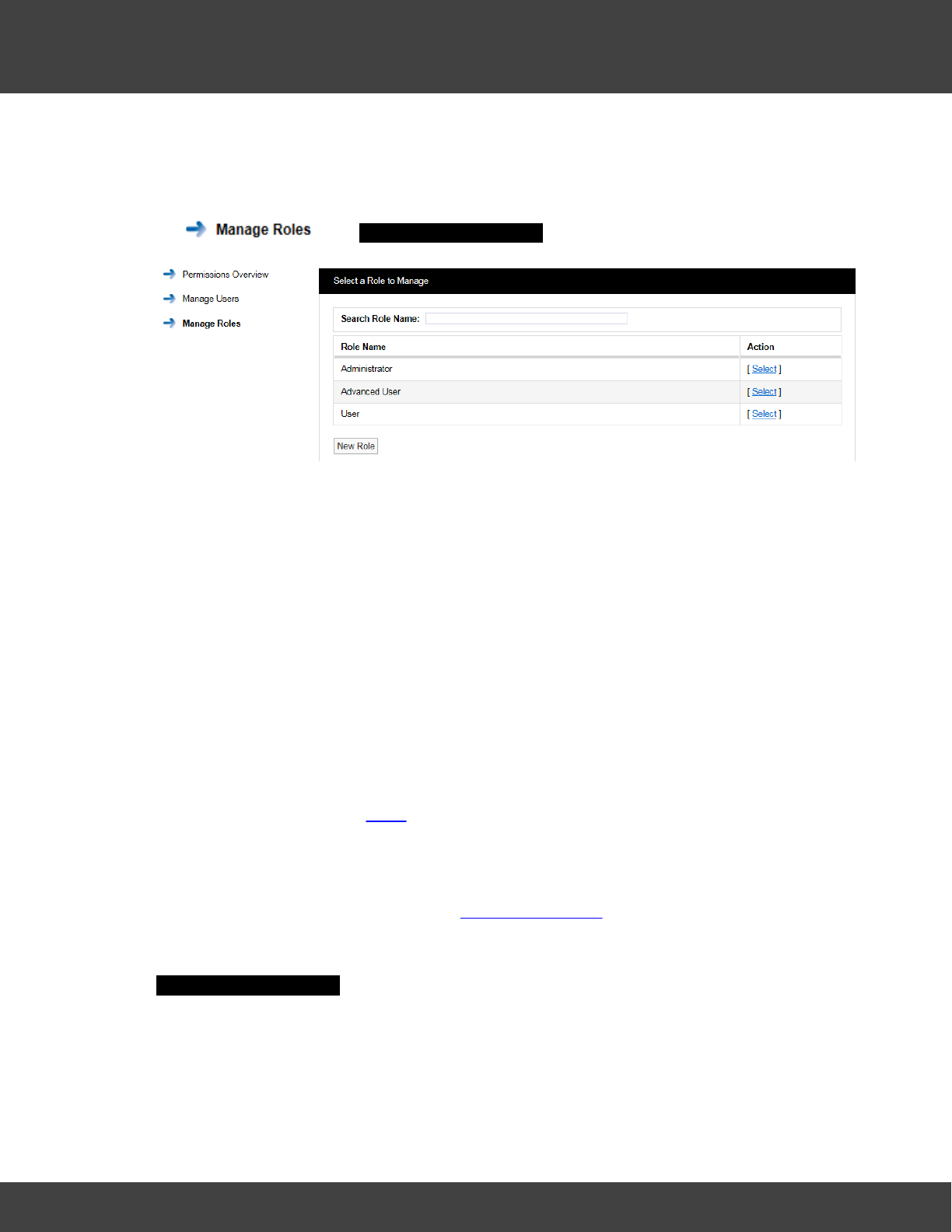
84
Notion Pro © 2017 IMC Group Ltd HP5525 Version 1.2.15
Reference Section
the user has been assigned, this process is described below.
Manage Roles
Before you can assign Permissions to a user you need to create Roles. To view Roles click
on . The Select a Role to Manage window will appear see below.
When Notion Pro is installed there are no pre-defined Roles set. The Admin User can create
Roles and decide what Permissions to assign to each Role. The list below shows a typical
set of Role. There is no limit to the amount of Roles that can be set.
·Administrator
This would be a high level Role with all Permissions assigned.
·Advanced User
These would be trusted users with access to Admin functions blocked but still able to edit
sensor properties. Full data viewing and alarm acknowledging allowed.
·General User
These would be lower level users with access to Admin functions and sensor editing
blocked. Full data viewing is allowed.
·Guest User
These would be view-only users with no editing or alarm acknowledging rights. Full data
viewing is allowed. See also Roles.
When Notion Pro is installed a default Admin User is created. The Admin User cannot be
deleted and is preset with the Username “Admin User” and the Password “Admin”. We
recommend that these details are changed immediately after installation. This can be done
from Admin>User Management see User Management. The Default Admin User is pre-
assigned with all available Permissions.
When setting up from first install, select Admin>Access Control>Manage Roles. The
Select a Role to Manage window appears see below.
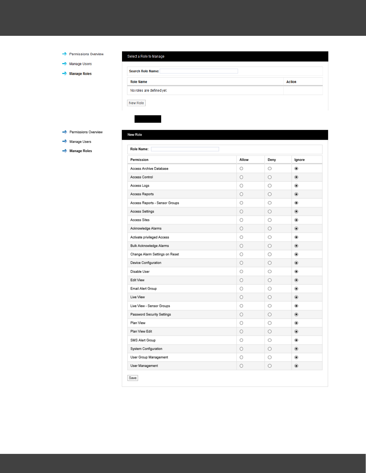
85
Notion Pro © 2017 IMC Group Ltd HP5525 Version 1.2.15
Reference Section
Click on New Role. The New Role window appears see below.
Enter a name for the Role. We would recommend using Administrator for the highest level
user. It is also suggested that all functions are set to Allow with the exception of Activate
privileged Access which should be set to Deny. Select Save. You have now created the
Administrator Role. See below.
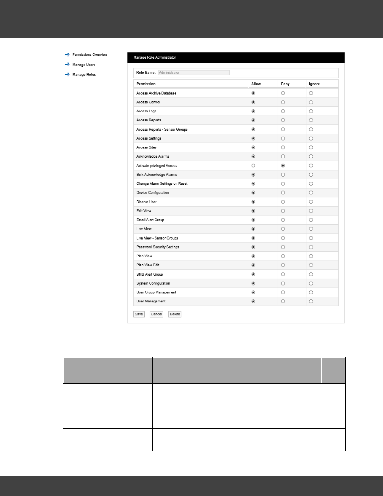
86
Notion Pro © 2017 IMC Group Ltd HP5525 Version 1.2.15
Reference Section
Other Roles can be created as required. following the instructions above.
Permission Definitions
Permission
Description
User
Level
Access Archive Database
Controls access to Archived read only data
M
Access Control
Controls access to the Access Control section
H
Access Logs
Controls access to System Logs
M
87
Notion Pro © 2017 IMC Group Ltd HP5525 Version 1.2.15
Reference Section
Permission
Description
User
Level
Access Reports
Controls access to Reports
M
Access Reports - Sensor
Groups
Controls access to the Sensor Groups, Reports menu
M
Access Settings
Controls access to entire Settings menu
H
Access Sites
Controls access to Sites meu
M
Acknowledging Alarms
Allows a user to acknowledge alarms
M
Acknowledge Alarms in Bulk
Allows user to acknowledge multiple sensors alarms
H
Activate privileged Access
Allows Admin User to login as the user, see note 1
below.
H
Change Alarm Settings on
Reset
Allows a user to change alarm values when resetting
an alarm
M
Device Configuration
Controls access to the Device Configuration menu.
H
Disable User
Allows a user to disable other users.
H
Edit View
Controls access to Edit Mode for Views.
M
Email Alert Group
Controls access to Email Alert Group settings
M
Live View
Controls access to the Live View, see note 2 below.
L
Live View - Sensor Groups
Controls access to Sensor Groups
L
Password Security Settings
Allows access to Password Security Settings screen
H
88
Notion Pro © 2017 IMC Group Ltd HP5525 Version 1.2.15
Reference Section
Permission
Description
User
Level
Plan View
Controls access to Plan View menu, see note 2
below.
L
Plan View Edit
Allows movement of sensors in Plan View
M
SMS Alert Group
Controls access to SMS Alert Group menu
M
System Configuration
Controls access to System Configuration menu
H
User Group Management
Controls access to User Group Management menu
H
User Management
Controls access to User Management menu
H
Key:
·HThese permissions are recommended for the highest level user only
·MThese permissions can be granted to general users
·LThese permissions can be granted to all users
Notes:
1. So the Admin User can configure settings which the normal user does not have access
to.
2. This should be available to all users.
Suggested Role Definitions
The following table gives suggested roles and the settings for those roles. You may wish to
define roles and permissions slightly differently for your Site.
Role
Permissions
General
Administrator
Select Ignore for:
·Access Control
·Access Logs
·Access Sites
89
Notion Pro © 2017 IMC Group Ltd HP5525 Version 1.2.15
Reference Section
Role
Permissions
·Activate privileged Access
·Disable User
·User Group Management
·User Management
Select the Allow option buttons for all other permissions.
Advanced User
Select Ignore for:
·Access Control
·Access Logs
·Access Sites
·Activate privileged Access
·Change Alarm Settings on Reset
·Device Configuration
·Disable User
·User Group Management
·User Management
Select the Allow option buttons for all other permissions.
Standard User
Select Ignore for:
·Access Reports
·Access Reports – Sensor Groups
·Access Settings
·Acknowledge Alarms
·Bulk Acknowledge Alarms
·Live View
·Live View – Sensor Groups
·Plan View
Select the Deny option buttons for all other permissions.
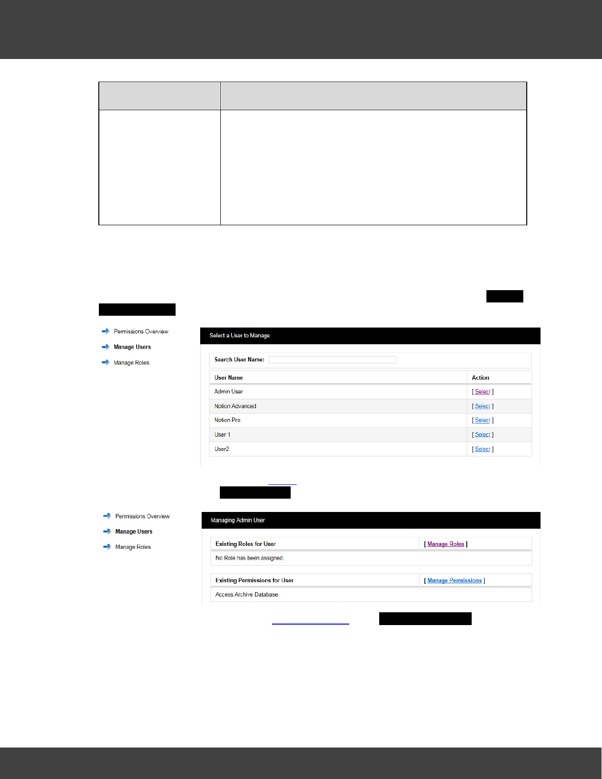
90
Notion Pro © 2017 IMC Group Ltd HP5525 Version 1.2.15
Reference Section
Role
Permissions
Guest User
Select Ignore for:
·Live View
·Live View – Sensor Groups
·Plan View
Select the Deny option buttons for all other permissions.
Manage Users
Notion Pro allows users to be associated with Roles rather than having to individually add
Permissions to each individual User. Permissions can also be done individually if required.
When setting up users, select Admin>Access Control>Manage Users. The Select a
User to Manage window appears. See below.
To assign a User to a Role click on Select next to the user name that you want to assign a
Role to, see above. The Managing User window appears, see below.
To assign a Role to this User select Manage Roles. The Manage User Roles window
appears. See below.
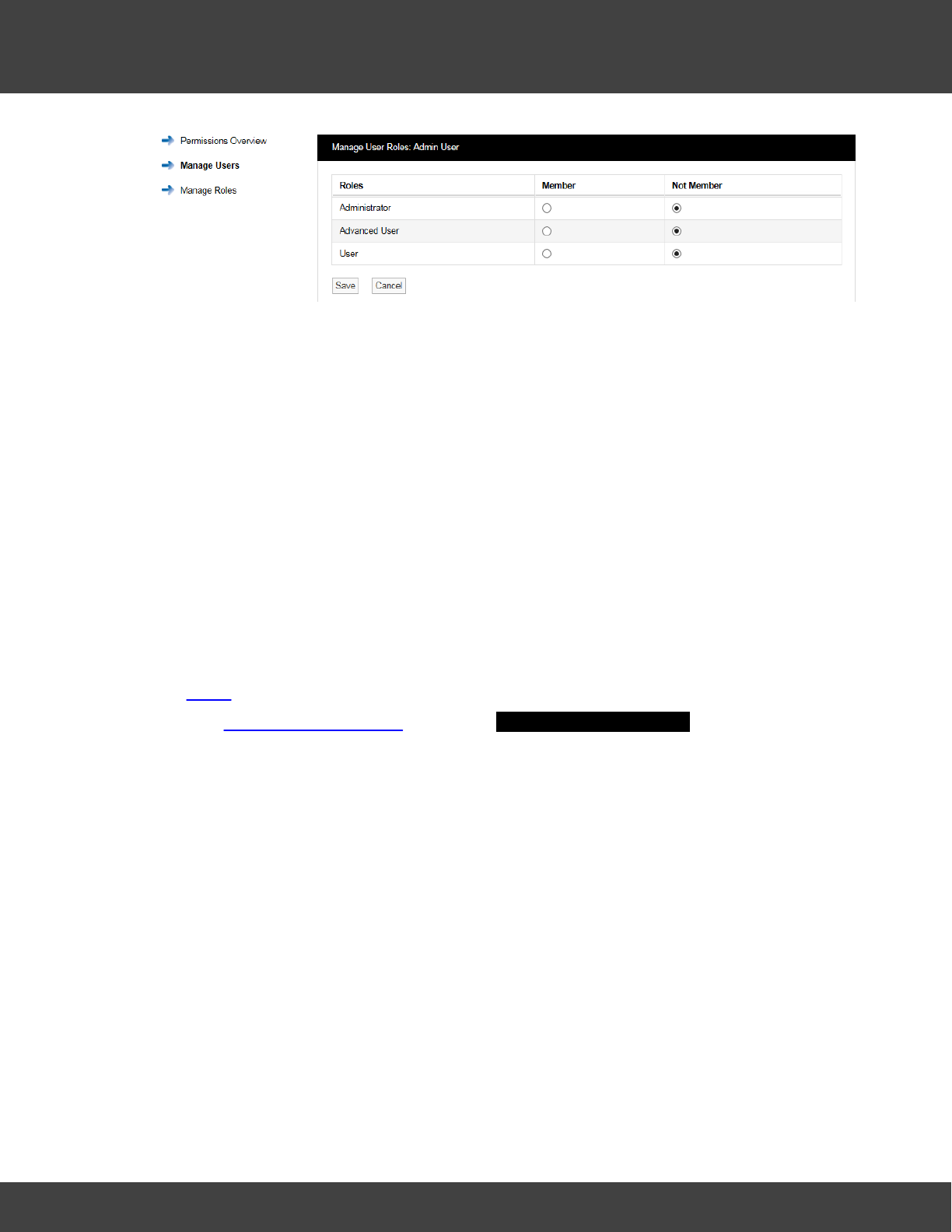
91
Notion Pro © 2017 IMC Group Ltd HP5525 Version 1.2.15
Reference Section
In this case the previously selected User was the Administrator user, so we need to select
the Member option button next to Administrator to put this user into the Administrator
Role. This user will now inherit the Permissions assigned to this Role. More than one user can
be assigned to the same Role.
A user can be assigned to more than one Role, for example a lower level user can be
assigned a higher set of Permissions by an Admin user on a temporary basis. This allows a
user to stand in for a colleague without the need to access the user settings and individually
change the Permissions.
User Permissions
The main method for Notion Pro users to be granted Permissions is by association to a
Role. For total flexibility an individual user can have some permissions Allowed or Denied
rather than inherited.
To Manage Permissions for a User:
1. Select Manage Users to give the Select a User to Manage dialogue box.
2. Select the required user to give the Managing <user name> dialogue box.
3. Click Manage Permissions to give the Manage User Permissions window. See below.
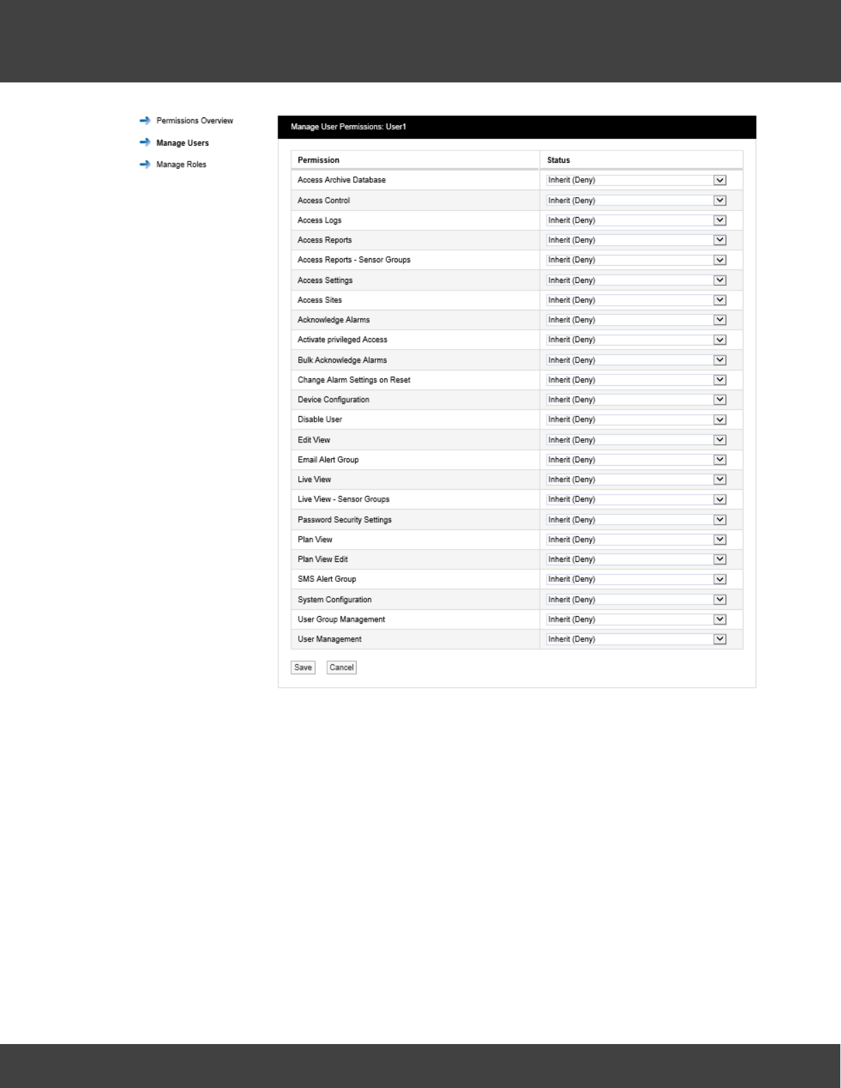
92
Notion Pro © 2017 IMC Group Ltd HP5525 Version 1.2.15
Reference Section
To change a Permission select the drop down arrow next to the Permission to be changed
and select either Allow or Deny. The above process can be repeated for other Users and
Roles.
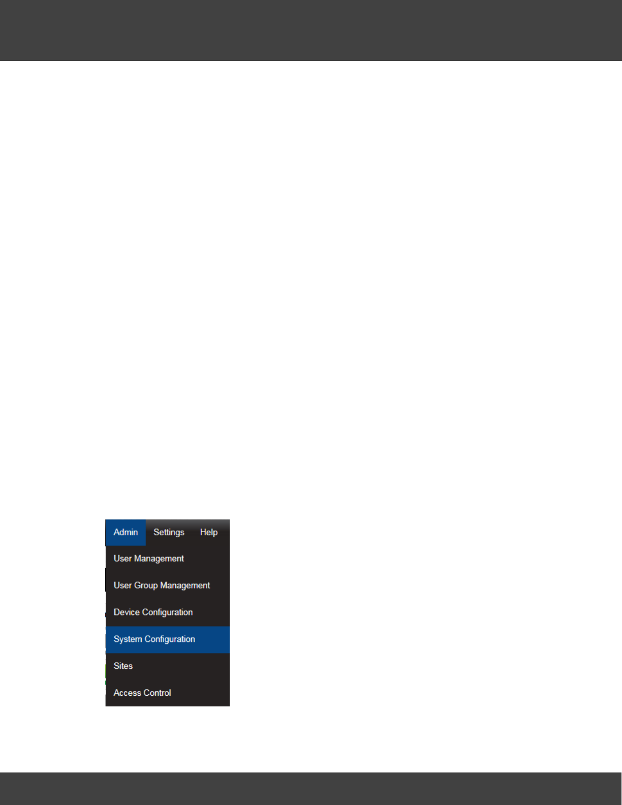
93
Notion Pro © 2017 IMC Group Ltd HP5525 Version 1.2.15
Reference Section
5.2.4 System Configuration
This section describes where SMS settings are set for the automated alarm functions.
Email Alerts enable Notion Pro Users to be emailed with the status of Notion Pro. Email Alerts
can also be set to enable Notion Pro Users to be emailed if a sensor goes into Alarm
condition. If your Site has an SMS Module then users can get text messages to inform
them of alarm conditions.
Note: You should have details of values and settings for the following items. These details
should be completed in the IceSpy Notion Pro Pre-Requisites document, doc. no.
IM5546:
·SMTP Mail Server name
·Sender Email Address
·SMTP Username
·SMTP Password
·BCC Email Address
·Heartbeat Enable setting
·Email Alert Heartbeat Time setting
·Email Receiving Protocol (optional)
·Receive Email over SSL setting (optional)
·IMAP/POP3 Mail Server Name (optional)
·IMAP/POP3 User Name (optional)
·IMAP/POP3 User Password (optional)
Select Admin>System Configuration from the drop down
menu to access the System Configuration section.
After selecting System Configuration a new window appears,
see below.
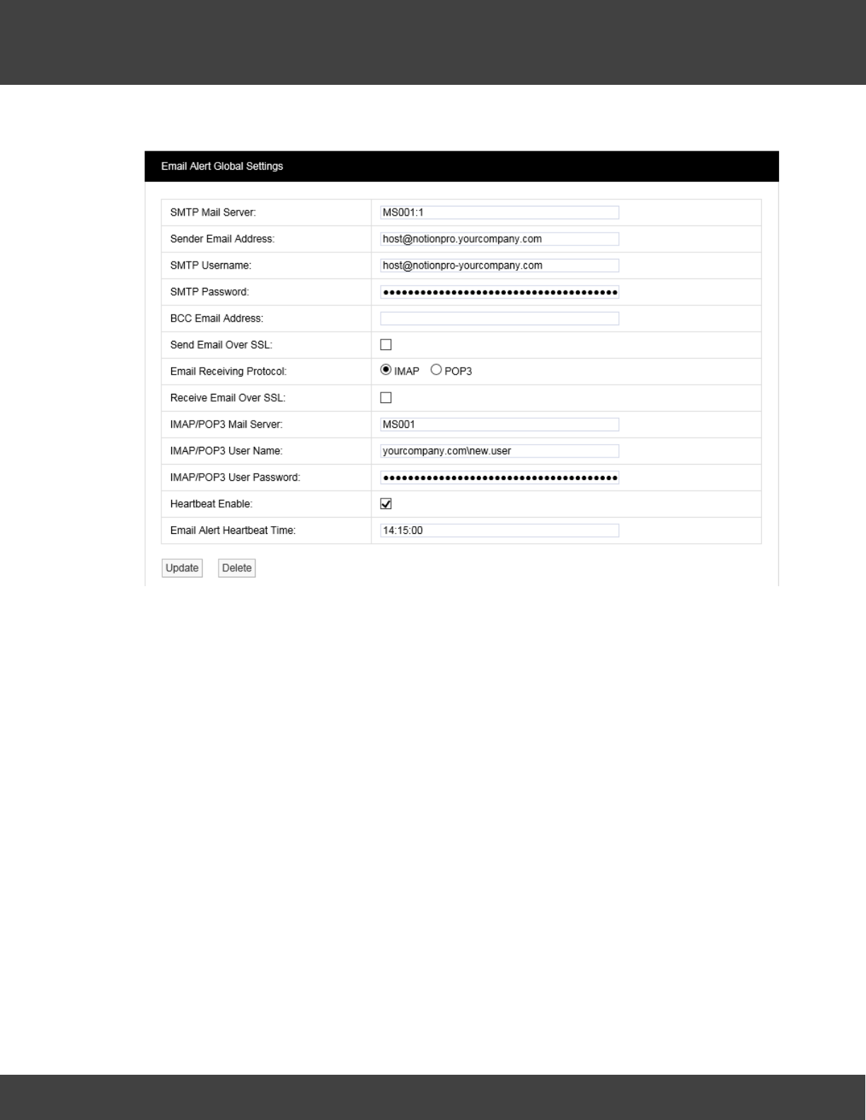
94
Notion Pro © 2017 IMC Group Ltd HP5525 Version 1.2.15
Reference Section
Email Alert Global Settings
The in the above example details ideally should have been collected prior to installation and if
available will be on the Notion Pro Pre-Requisites document. If the details are not available at
the time of commissioning, you will need to contact your IT department or provider. If the
details are available enter them into the dialog boxes above.
It is not essential that these details are entered at this time. If email alerts and emailed
reports are not required at this point these details can be entered at a later date.
Mail Servers can be specified as a resolvable hostname or IPv4 address. The example
settings, shown above use standard IANA assigned port numbers when connecting to the
mail server(s). If required you can specify the port number to be used, by adding a colon ‘:’
followed by the required port number to the server hostname or IPv4 address; e.g.
‘MS001:25’ would use port 25.
If you do not know the address(s) and/or port number(s) used by your Mail server, contact
your system administrator or IT support provider. Do NOT contact IMC Technical Support,
as this is information that only your IT administrator or support provider can supply.
It is recommended that the Heartbeat message is enabled, the problem with automated
alarm systems using tools such as email, is if you don’t get an alarm for several days or
weeks then it is difficult to know if that is because the system is not generating any alarms
or is it because the email system has failed. The Heartbeat message will give a daily
indication that everything is functioning correctly. The timing of the Heartbeat message can
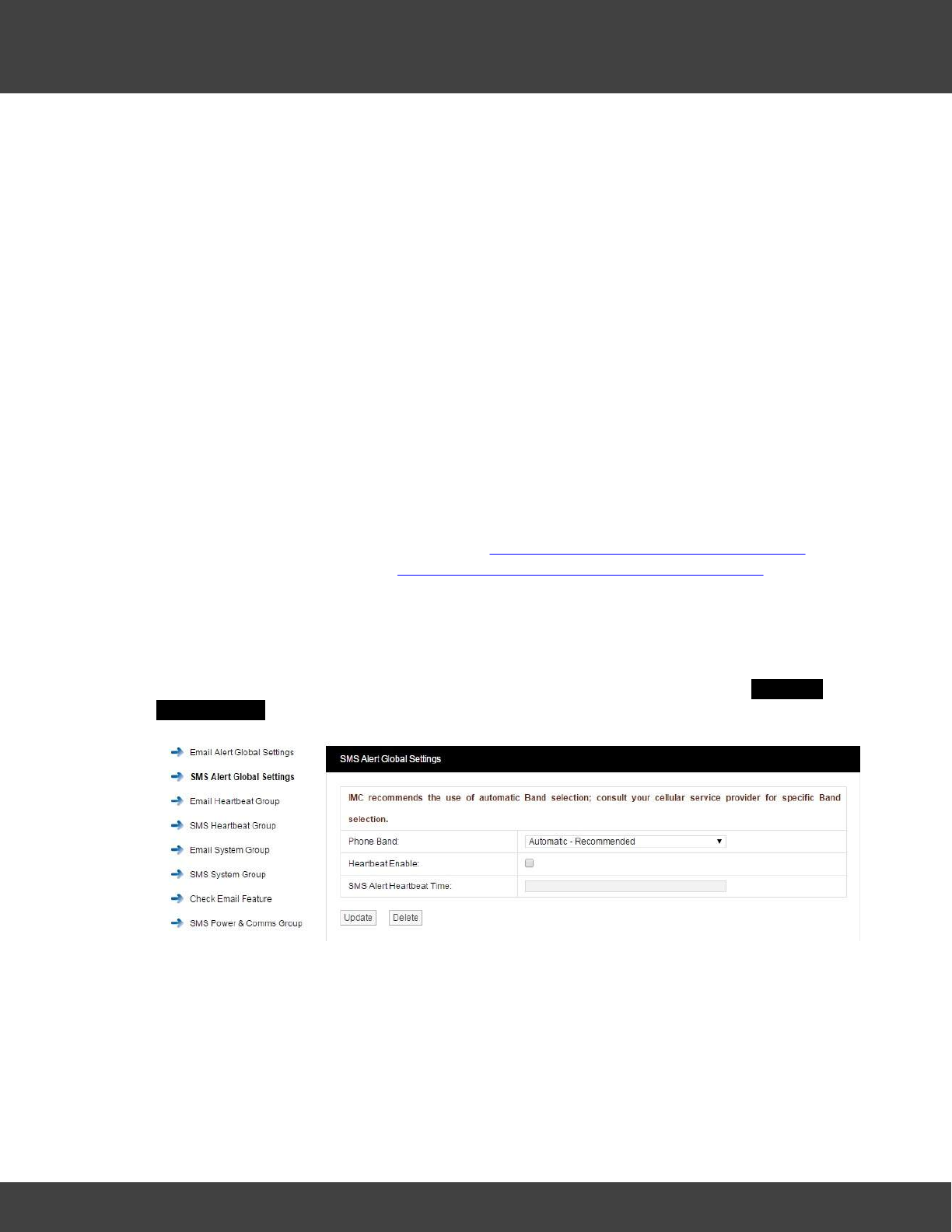
95
Notion Pro © 2017 IMC Group Ltd HP5525 Version 1.2.15
Reference Section
be set in the bottom dialog box, please ensure that the time is entered in the following
format:
·14:15:00
Any time from the 24 hour clock can be set. When all settings are entered select Update.
The Receive Email and IMAP/POP3 settings are for email alert acknowledgement handling,
and can be left blank should this feature not be required.
Note: Do NOT set the BCC Email Address to be the same as the Sender Email Address.
Warning: It is not recommended that email alerts are used on their own for critical alarms.
Email alerts rely on your internal email systems functioning correctly. Or if your Internet
Service Provider is suffering any problems this will also cause disruption of service.
For critical alarms IMC recommends the use of two different methods to send out alarm
alerts. Other forms of alarm alert generation methods are SMS driven from the SMS Module
GSM device or hard wired relays driven locally from the Network Receivers. Both methods
require extra hardware.
Contact your IceSpy sales representative or your local distributor for further details. Contact
information can be found on our website at http://www.the-imcgroup.com/contact-us for
our UK Head office contacts or http://www.the-imcgroup.com/global-distributors to contact
one of our authorised distributors
SMS Alert Global Settings
Notion Pro allows alarm alerts to be sent out via SMS Alerts.
To set up SMS Alert Global Settings, select SMS Alert Global Settings, the SMS Alert
Global Settings Window will appear see below.
IMC recommend that the SMS unit is set to auto-detect the phone band; however, the
Phone Band drop down control can be used to select a specific band for your service
provider.
It is recommended that the Heartbeat message is enabled. The problem with automated
alarm systems using tools such as SMS is, if you don’t get an alarm for several days or
weeks then it is difficult to know if that is because the system is not generating any alarms
or is it because the SMS system has failed. The Heartbeat message will give a daily
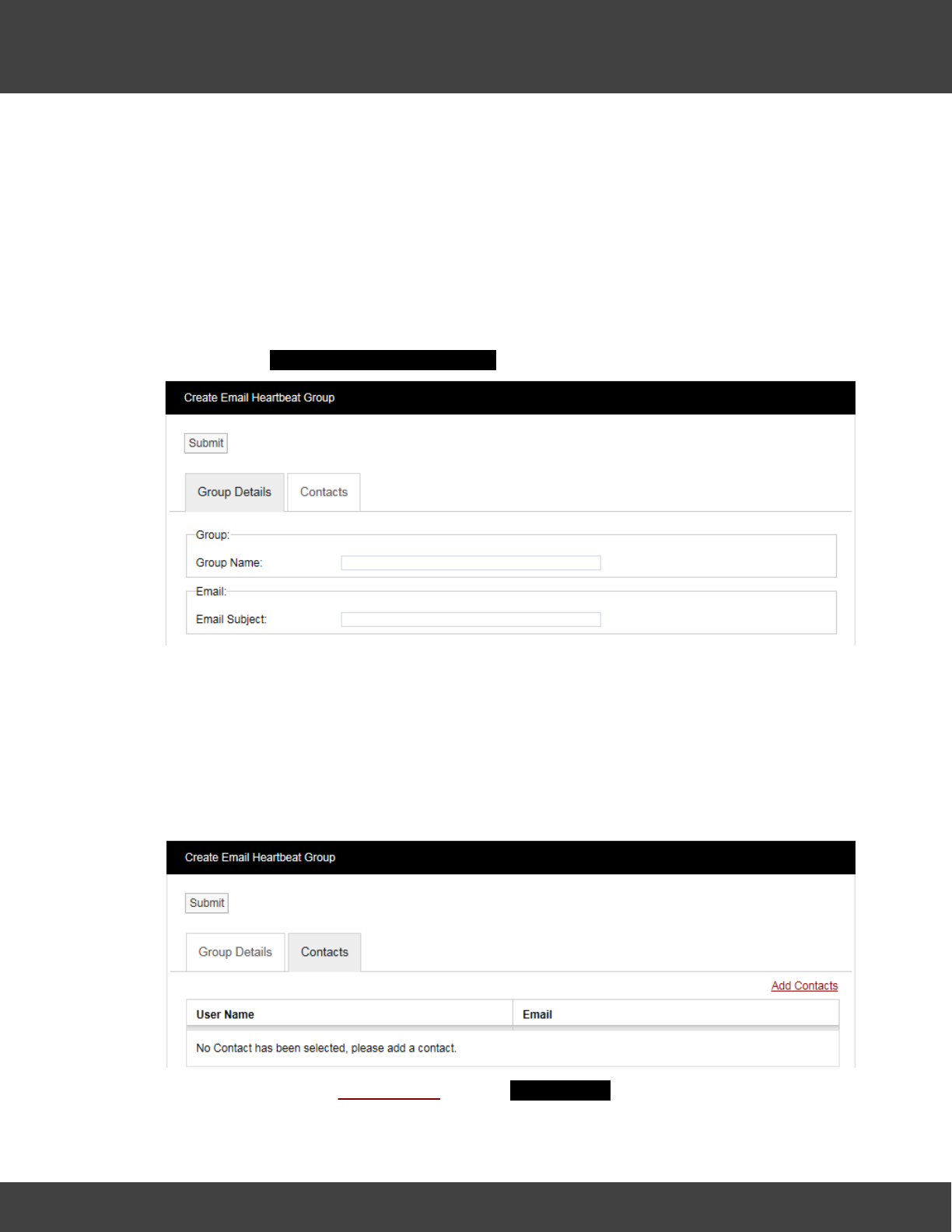
96
Notion Pro © 2017 IMC Group Ltd HP5525 Version 1.2.15
Reference Section
indication that everything is functioning correctly. The timing of the Heartbeat message can
be set in the bottom dialog box, please ensure that the time is entered in the following
format:
·10:10:00
Any time from the 24 hour clock can be set. When all settings are entered select Update.
Email Heartbeat Group
You can create the Email Heartbeat Group which allows multiple users to be allocated to a
group. To create the Email Heartbeat Group select Email Heartbeat Group from the side
menu and the Create Email Heartbeat Group Window will appear see below.
Step 1
Enter a name for the group in the dialog box next to Group Name, then enter a phrase in
the dialog box next to Email Subject. The text entered here will become the subject of the
email.
Step 2
Click on the Contacts tab and the Contacts dialog box appears, see below.
To add Contacts select Add Contacts and the Add Contacts window appears, see below.
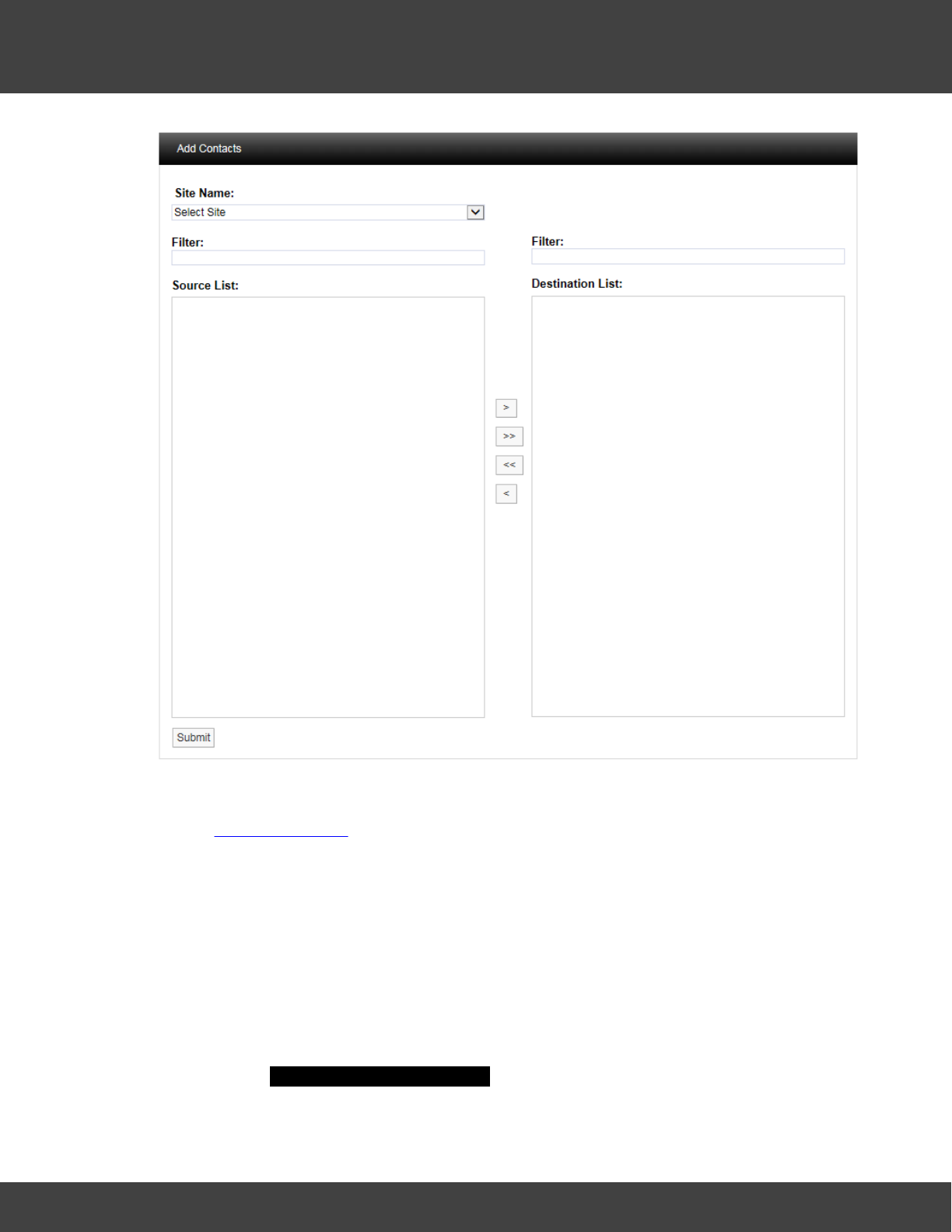
97
Notion Pro © 2017 IMC Group Ltd HP5525 Version 1.2.15
Reference Section
Select a Site from the Site Name drop-down menu on the dialog box. On initial setup there
will only be one Site available which is created during the installation. See more about creating
Sites in Site Management.
The selected Site's associated contacts will appear in the left window, when the Site
contacts/users list is long the required Contacts can be found by using the Filter. Select the
right-facing arrow to move the Contact to the right window. More than one Contact can be
moved across. Once you are happy with your selection of Contacts select the Submit
button at the bottom left. This will return you to the Edit Email Heartbeat Group window.
Select the Update button to save the group.
SMS Heartbeat Group
You can create the SMS Heartbeat Group, which allows multiple users to be allocated to a
group. To create the SMS Heartbeat Group select SMS Heartbeat Group from the side
menu and the Create SMS Heartbeat Group window will appear see, below.
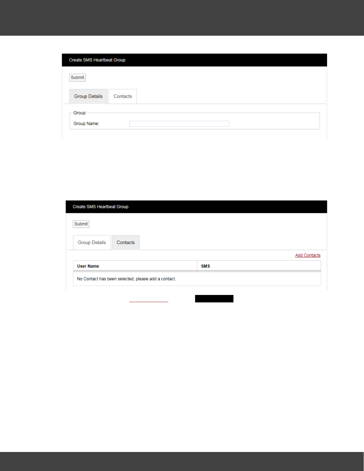
98
Notion Pro © 2017 IMC Group Ltd HP5525 Version 1.2.15
Reference Section
Step 1
Enter a name for the group in the dialog box next to Group Name.
Step 2
Click on the tab marked Contacts and the Contacts dialog box appears, see below.
To add Contacts select Add Contacts and the Add Contacts window appears, see below.
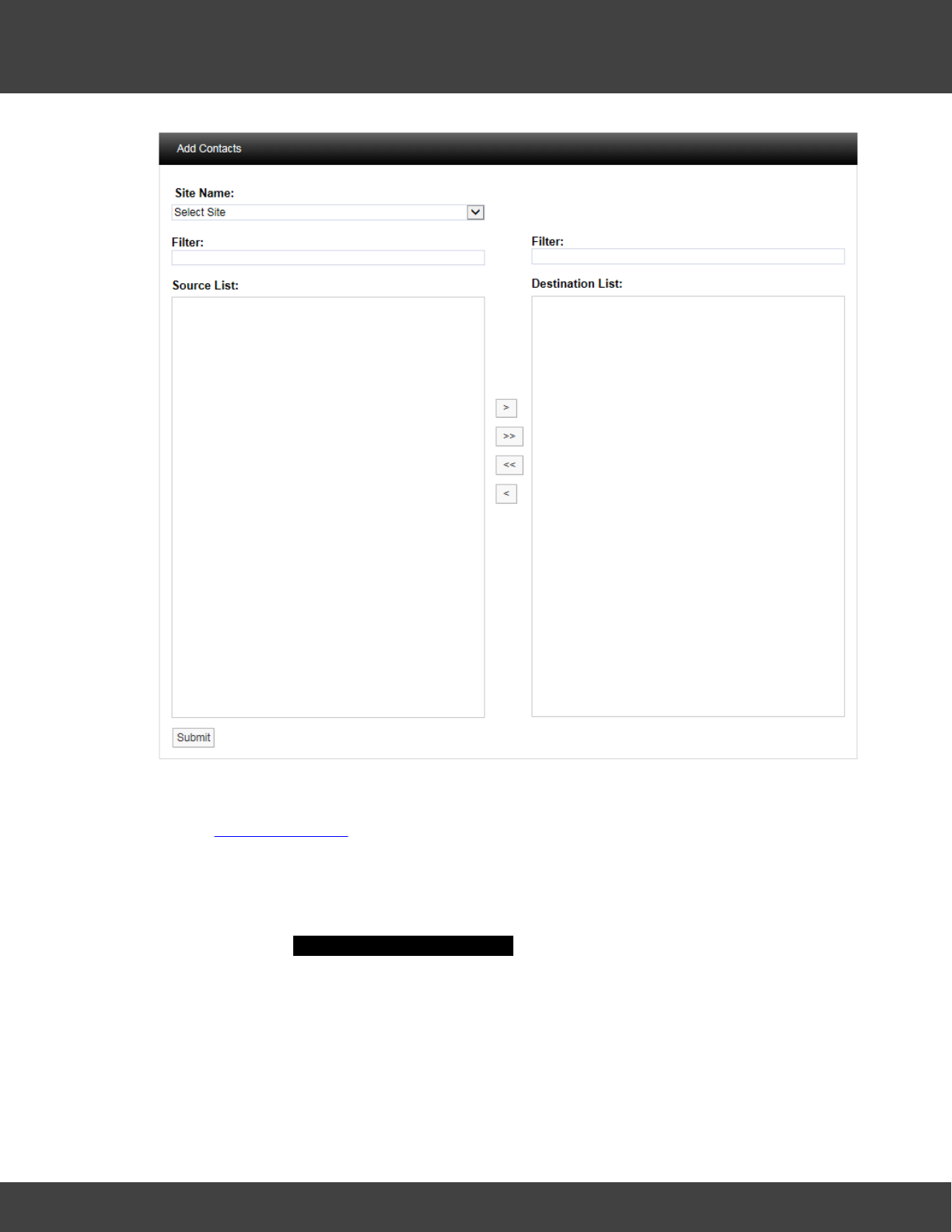
99
Notion Pro © 2017 IMC Group Ltd HP5525 Version 1.2.15
Reference Section
Select a Site from the Site Name drop-down menu on the dialog box. On initial setup there
will only be one Site available which is created during the installation. See more about creating
Sites in Site Management.
The selected Site's Contacts will appear in the left window, when the Contact list is long the
required Contact can be found by using the Filter. Select the right facing arrow to move the
Contact to the right window. More than one Contact can be moved across. Once you are
happy with your selection of Contacts select the Submit button at the bottom left. This will
return you to the Create SMS Heartbeat Group window. Select the Submit button to save
the group.
Email System Group
You can create the Email System Group, which sends email alerts from a predefined list of
System Events. These events are:
·Edit
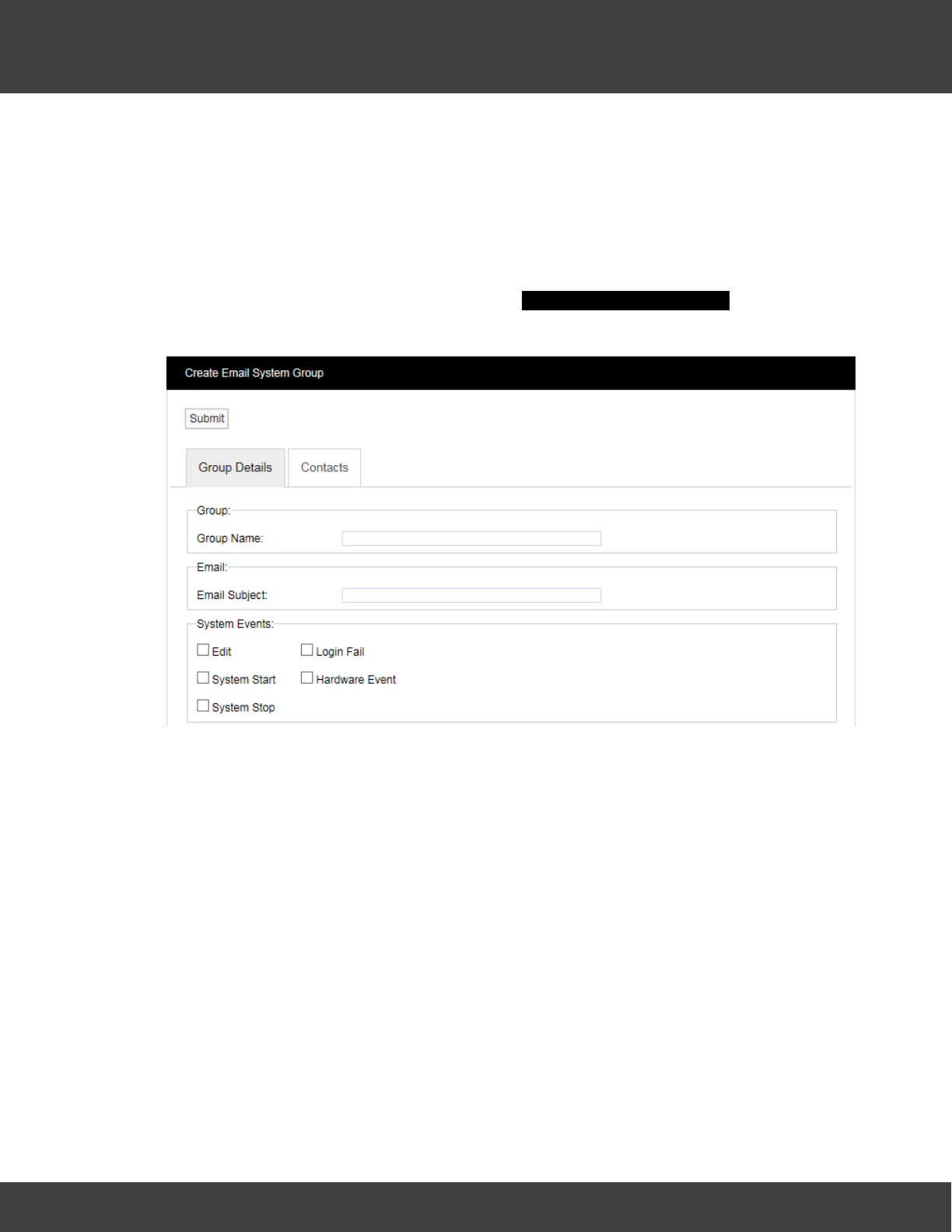
100
Notion Pro © 2017 IMC Group Ltd HP5525 Version 1.2.15
Reference Section
·System Start
·System Stop
·Login Fail
·Hardware Event
Multiple users can be allocated to the group. To create the Email System Group select
Email System Group from the menu and the Create Email System Group window
appears, see below.
Step 1
Enter a name for the group in the text box next to Group Name, next enter a phrase in the
text box next to Email Subject. The text entered here will become the subject of the email.
Step 2
Select the parameters from the System Events panel that you require notification on.
Step 3
Click on the Contacts tab, see below.
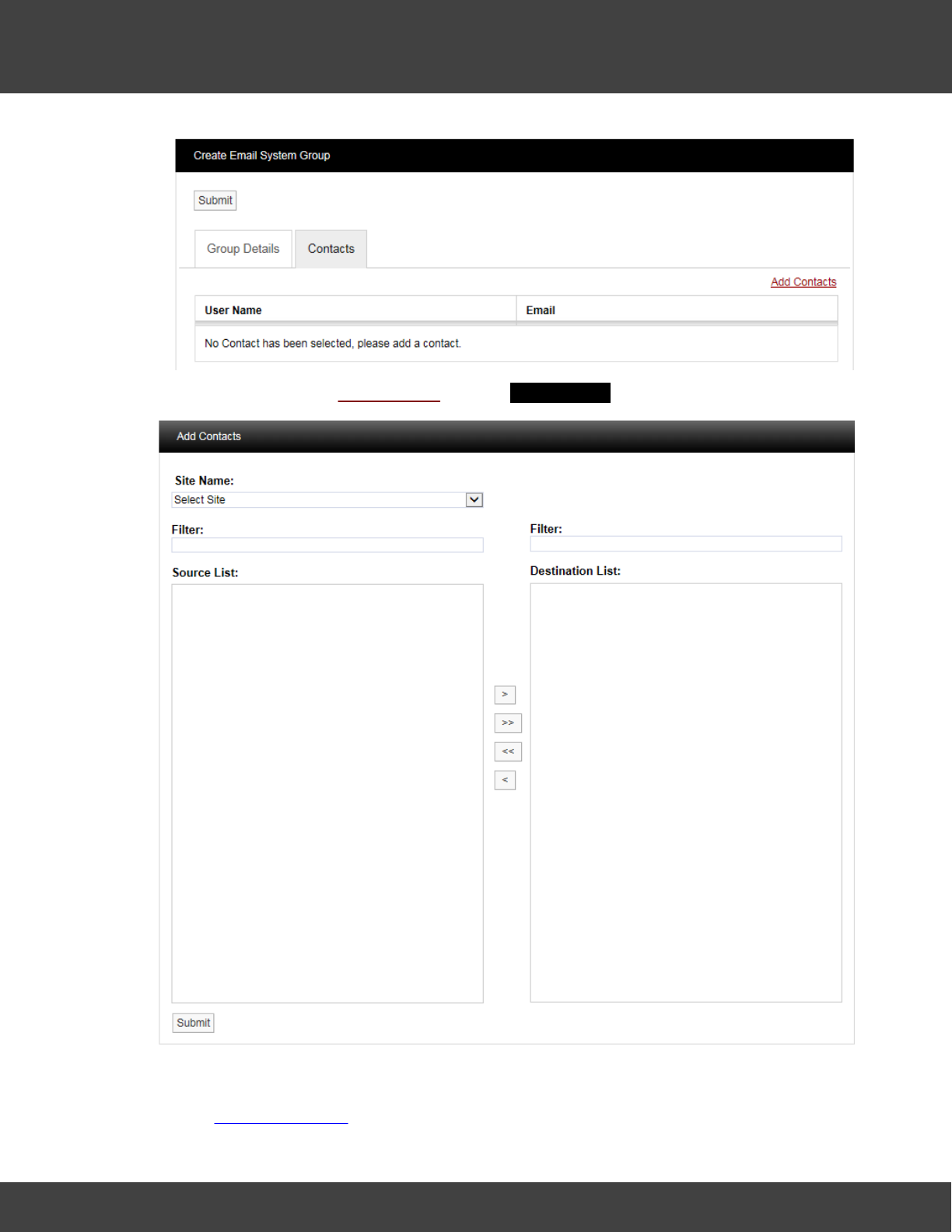
101
Notion Pro © 2017 IMC Group Ltd HP5525 Version 1.2.15
Reference Section
To add Contacts select Add Contacts and the Add Contacts Window will appear, see below.
Select a Site from the Site Name drop-down menu on the dialog box. On initial setup there
will only be one Site available which is created during the installation. See more about creating
Sites in Site Management.
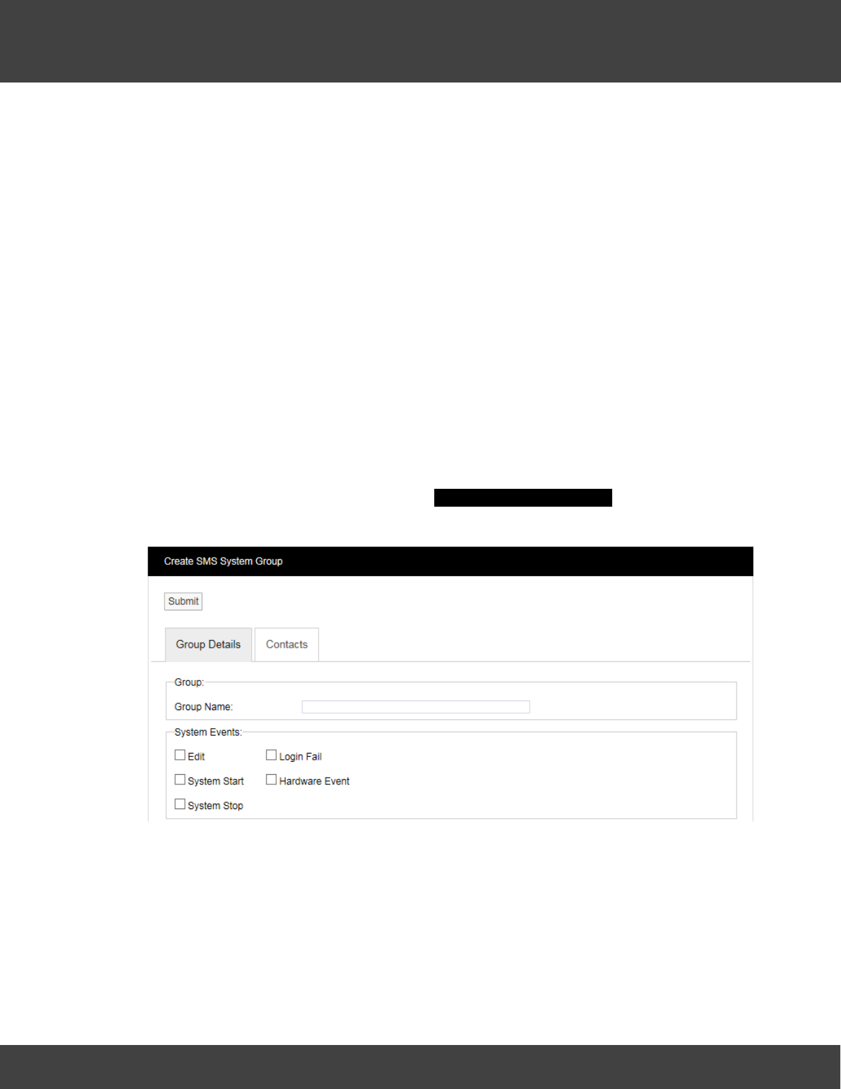
102
Notion Pro © 2017 IMC Group Ltd HP5525 Version 1.2.15
Reference Section
The selected Site's contacts will appear in the left window, when the Site contacts list is long
the required Contact can be found by using the Filter. Select the right facing arrow to move
the Contact to the right window. More than one Contact can be moved across. Once you
are happy with your selection of Contacts select the Submit button at the bottom left. This
will return you to the Create Email System Group window. Select the Submit button to save
the group.
SMS System Group
You can create the SMS System Group. The SMS System Group, which sends SMS alerts
from a predefined list of System Events. These events are:
·Edit
·System Start
·System Stop
·Login Fail
·Hardware Event
Multiple users can be allocated to a group. To create an SMS System Group select SMS
System Group from the side menu and the Create SMS System Group window will appear,
see below.
Step 1
Enter a name for the group in the dialog box next to Group Name.
Step 2
Select the parameters from the System Events panel that you require notification on.
Step 3
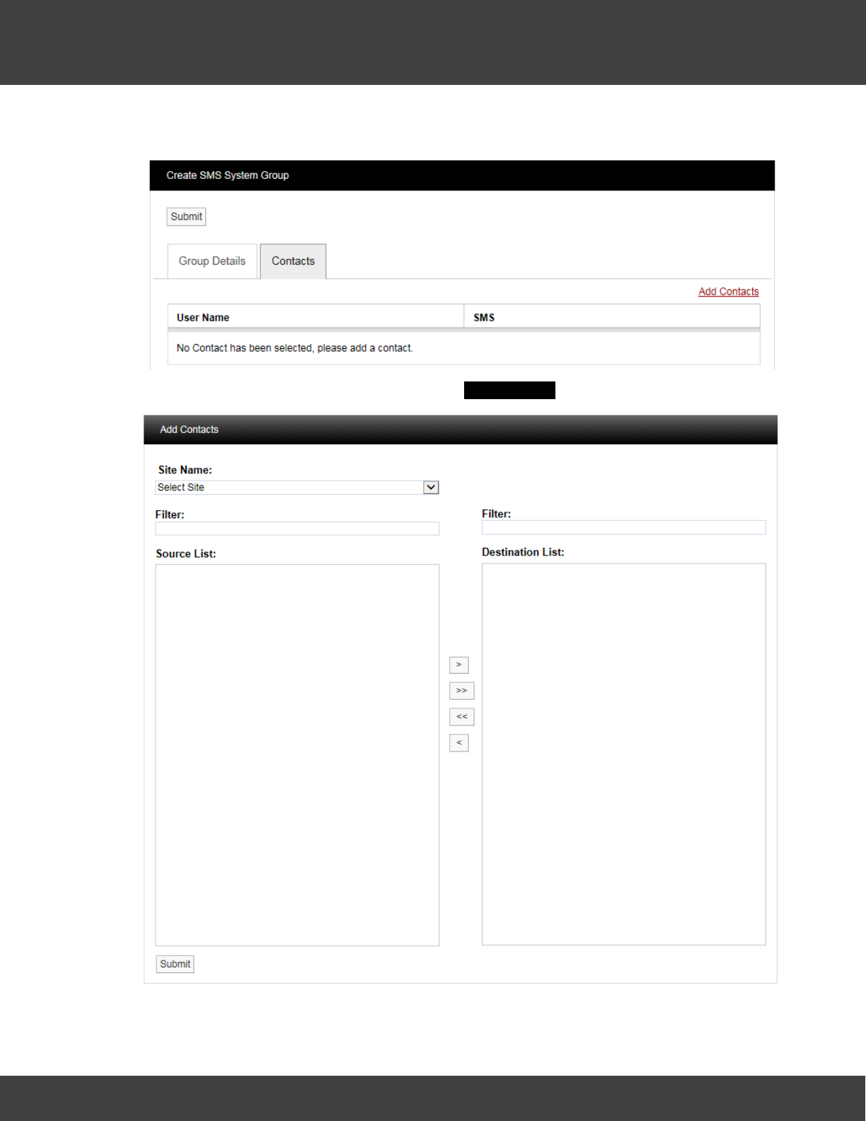
103
Notion Pro © 2017 IMC Group Ltd HP5525 Version 1.2.15
Reference Section
Click on the Contacts tab and the Contacts dialog box appears, see below.
To add Contacts select Add Contacts and the Add Contacts window appears. See below.
Select a Site from the Site Name drop-down menu on the dialog box. On initial setup there
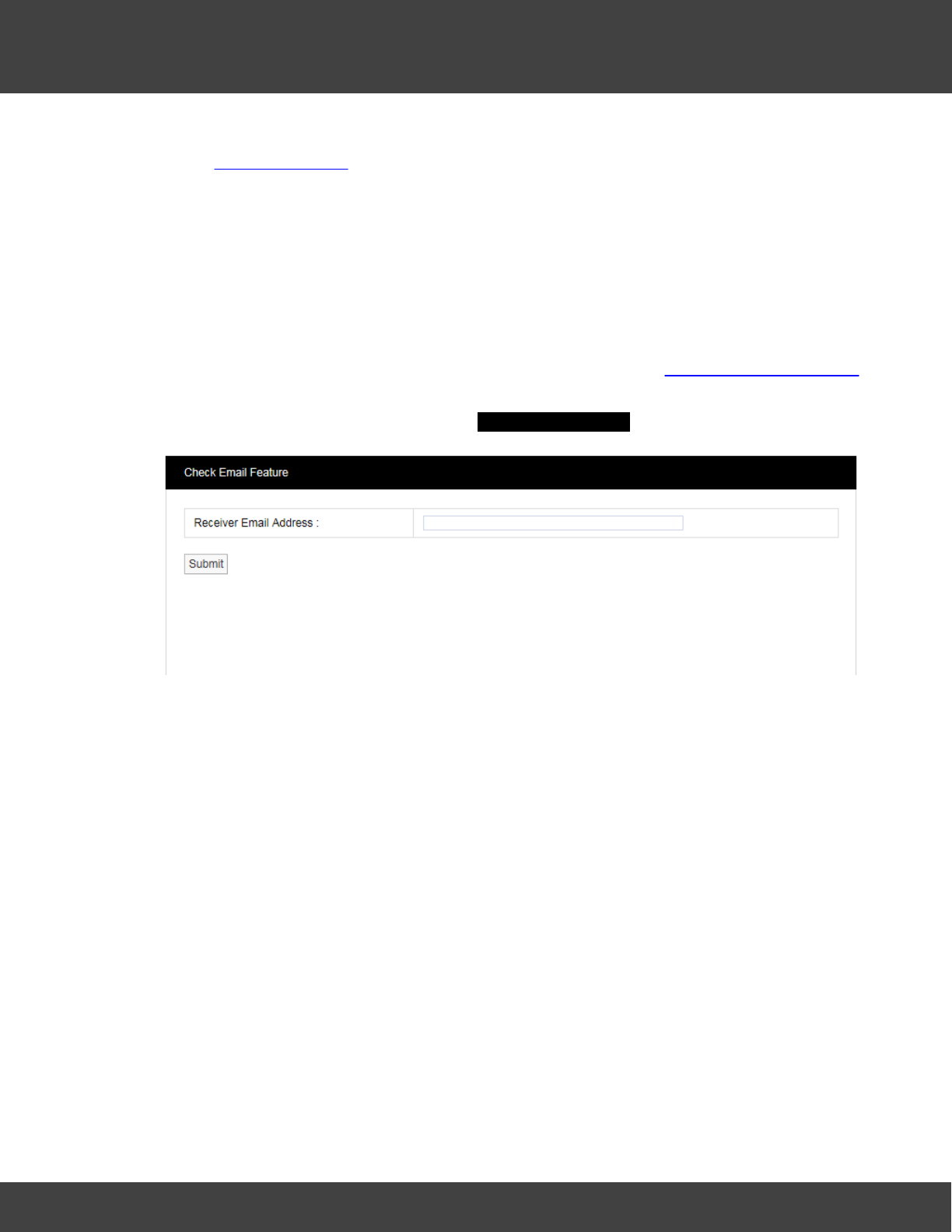
104
Notion Pro © 2017 IMC Group Ltd HP5525 Version 1.2.15
Reference Section
will only be one Site available which is created during the installation. See more about creating
Sites in Site Management.
The selected Site's contacts will appear in the left window, when the Site contacts list is long
the required Contact can be found by using the Filter. Select the right facing arrow to move
the Contact to the right window. More than one Contact can be moved across. Once you
are happy with your selection of Contacts select the Submit button at the bottom left. This
will return you to the Create SMS System Group window. Select the Submit button to
save the group.
The Check Email Feature
This can be used verify that the settings that have been set up in Email Alert Global Settings
function correctly and that you can receive an email from Notion Lite.
Select Check Email Feature to give the Check Email Feature dialog box, see below.
Enter your email address into the Receiver Email Address field then click Submit – you should
receive an email from Notion Pro.
SMS Power & Comm's Group
This Group is used to set up a list of phone numbers to receive SMS messages, should the
IMC SMS Module detect a power failure or lose of communications with the Notion Pro
server.
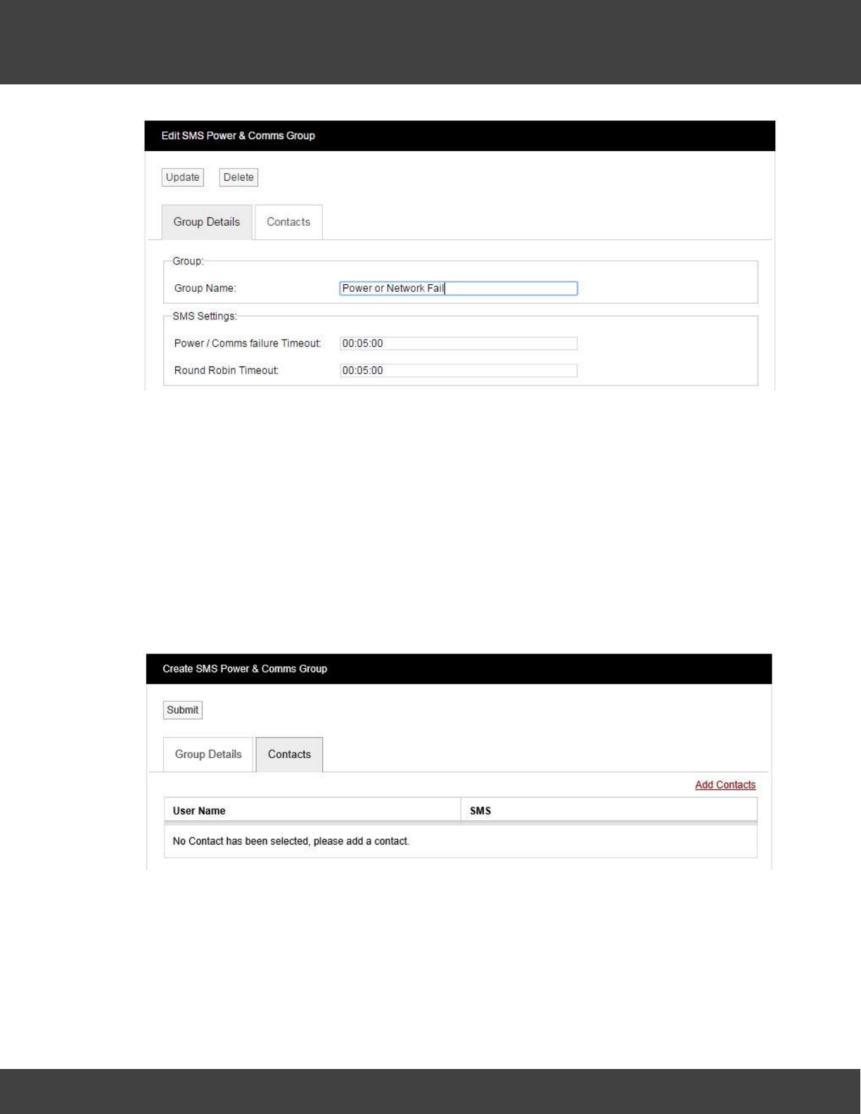
105
Notion Pro © 2017 IMC Group Ltd HP5525 Version 1.2.15
Reference Section
Enter the required Group name, Power / Communication failure timeout and Round Robin
Time.
Group name - user set name, this appears at the start of the SMS sent on the event of a
Power or Communications failure.
Power / Comm's failure Timeout - period the IMC SMS Module will wait after a Power or
Communications failure, before sending SMS messages.
Round Robin Timeout - period the IMC SMS Module will wait between sending each SMS
message to the contacts assigned to the group.
Click on the Contacts tab to display the current list of contacts set to receive the SMS
messages.
To add or edit Contacts, click Add Contacts, the Add Contacts screen will display as
below.
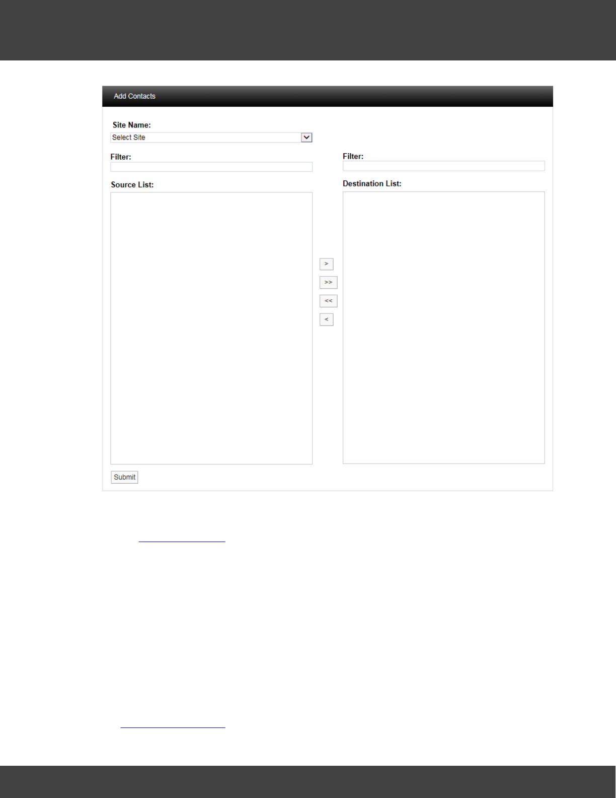
106
Notion Pro © 2017 IMC Group Ltd HP5525 Version 1.2.15
Reference Section
Select a Site from the Site Name drop-down menu on the dialog box. On initial setup there
will only be one Site available which is created during the installation. See more about creating
Sites in Site Management.
The selected Site's contacts will appear in the left window, when the Site contacts list is long
the required Contact can be found by using the Filter. Select the right facing arrow to move
the Contact to the right window. More than one Contact can be moved across. Once you
are happy with your selection of Contacts select the Submit button at the bottom left. This
will return you to the Create SMS Power & Comm's Group window. Select the Submit
button to save the group.
5.2.5 User Alerts
The options under this menu concern setting up user alerts by email and SMS. A user must
be a member of an Alert Group in order to receive messages specified when setting up
the System Configuration.
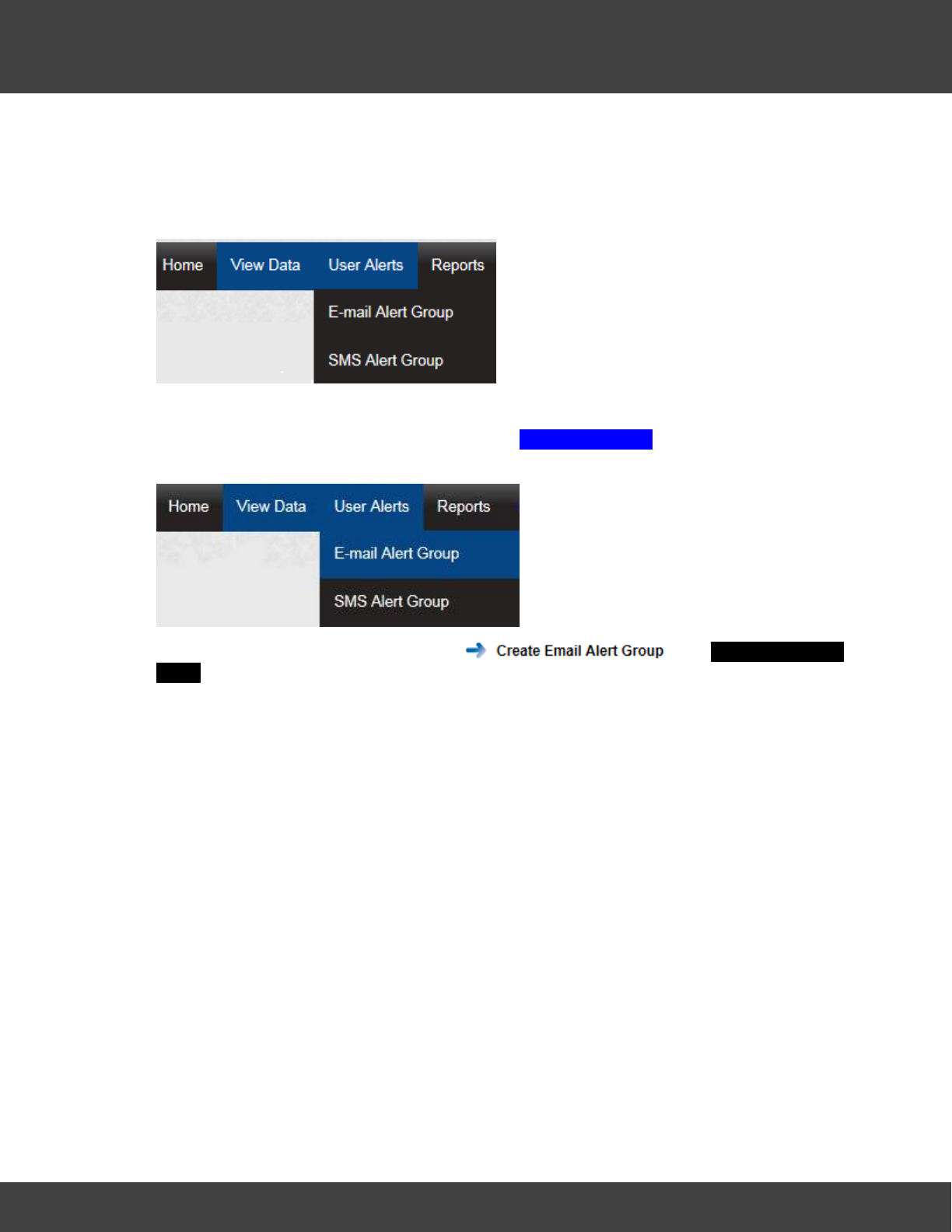
107
Notion Pro © 2017 IMC Group Ltd HP5525 Version 1.2.15
Reference Section
User Alerts provide automated Alarm notification delivered via Email or SMS or both. (An
SMS Module is required for SMS Alarms).
This section will take you through the use and settings for Email alarms and SMS Alarms. To
access the User Alert settings select User Alerts from the main menu, see below.
Email Alert Group
To access the Email Alert Group settings select E-Mail Alert Group from the menu, see
below.
After selecting E-mail Alert Group, select . The Create Email Alert
Group window appears, see below.
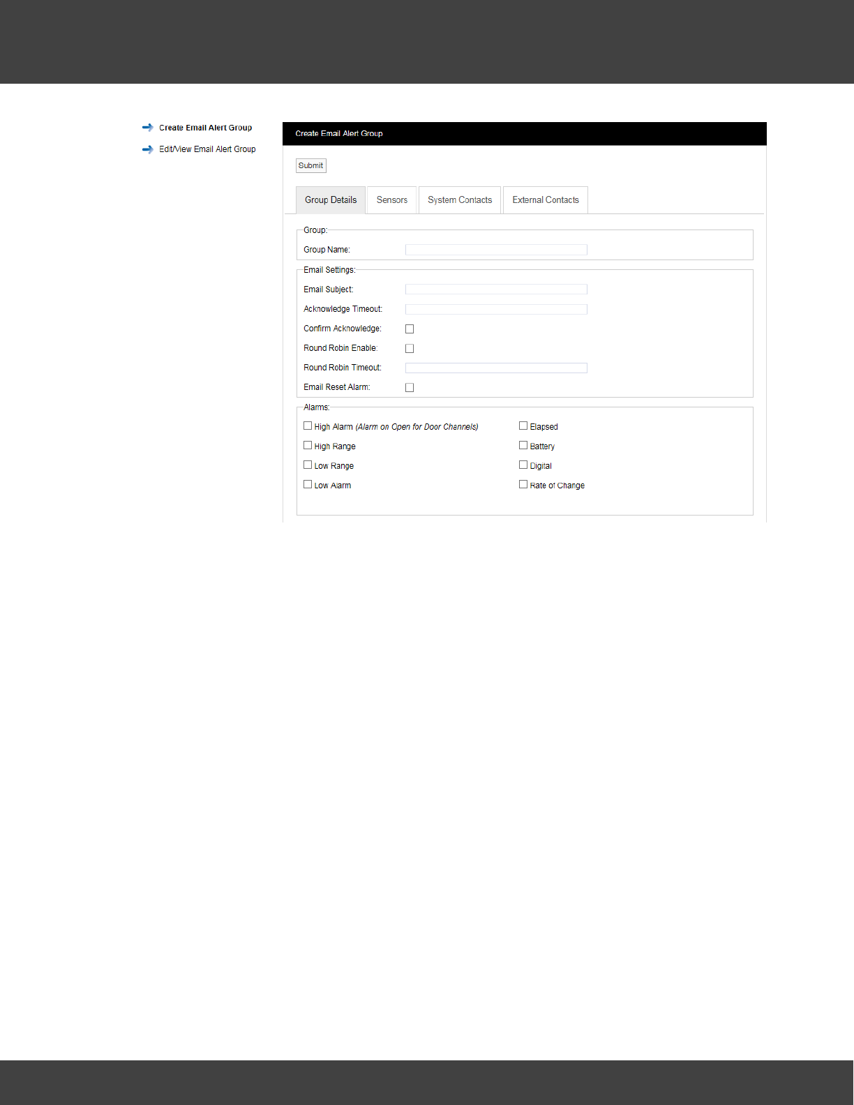
108
Notion Pro © 2017 IMC Group Ltd HP5525 Version 1.2.15
Reference Section
The window above allows Alert Groups to be created and configured for the automated
notification of email Alarms.
Step 1
Input a Group Name. This can be something that makes sense to the Site in question or
something related to the function. For this example, we will call the group, “Service Email”
this will be a Group that sends email Alarms to the Service Engineers.
Step 2
Enter a subject title for the Email into Email Subject. For this example we will call it “System
Alarm on Notion Pro Site” this would then alert the engineer in the email subject that they
were getting an email about an Alarm condition on that Site.
Step 3
Enter an Acknowledge Timeout. This is the time that the system will wait for an
acknowledgement email. This should be entered in time format like this 12:00:00, this would
be a 12 hour delay.
Step 4
Select the tick box next to Confirm Acknowledge if an acknowledgement email is required.
Step 5
Email Alerts can be sent in "Round Robin" mode. Round Robin mode is when email alerts are
sent to the first name in the list. If there is no response within the time limit the system
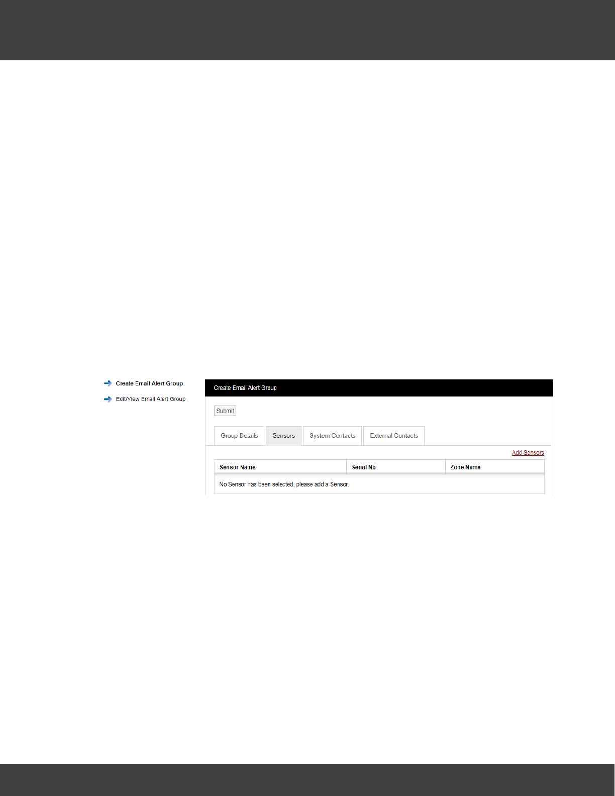
109
Notion Pro © 2017 IMC Group Ltd HP5525 Version 1.2.15
Reference Section
moves on to the next person in the list and so on until a response is received, or emails
have been sent to everybody in the list. To activate Round Robin mode select the tick box
next to Round Robin Enable.
Step 6
You can select the time period the system waits before sending the next email, this should
be entered in the Round Robin Timeout field in time format like this: 00:15:00. This would be
a 15 minute delay.
Step 7
If required, a reply email can be sent which will reset the alarms. To activate this feature
select the tick box next to Email Reset Alarm.
Step 8
Select the alarm parameters that Email Alerts are required for by clicking in the tick box next
to the alarm condition within the Alarms panel. Multiple selections can be made.
Step 9
Select the Sensors that you require to be included in the Alert Group. Click on the Sensors
tab. A new window will appear, see below.
To add sensors click the underlined Add Sensors link. A new window will appear, see below.
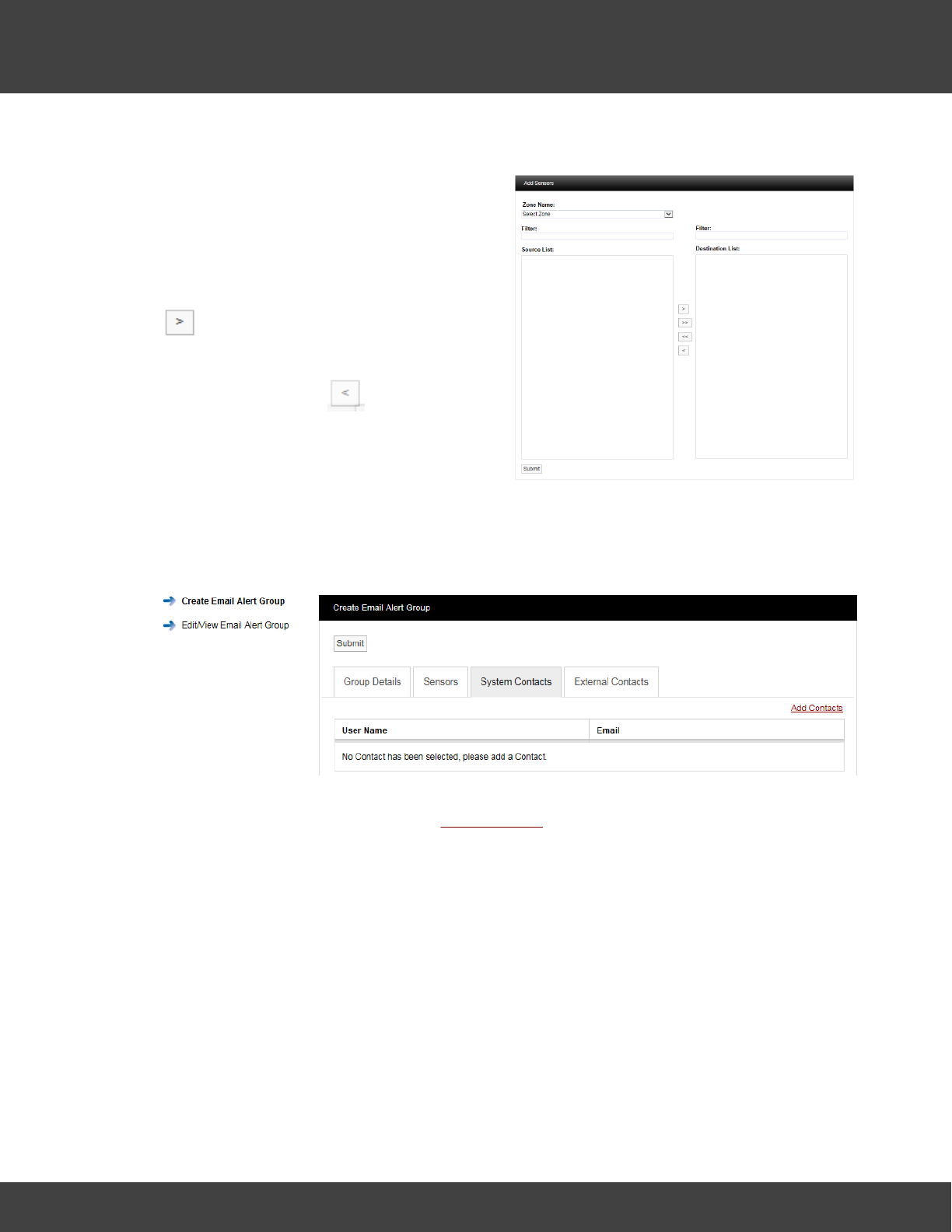
110
Notion Pro © 2017 IMC Group Ltd HP5525 Version 1.2.15
Reference Section
To select a Sensor first select a Zone from
the Zone Name: drop down menu.
As the Zone is selected the available sensors
in that Zone will populate the left column
(Source List).
To select Sensors highlight the ones that you
want to generate email alerts for then click
.
To deselect Sensors highlight them in the
right column and click .
To move all Sensors across click the double
arrows.
Once happy with you selection select
Submit.
To add Contacts to the Group select the System Contacts tab, see below.
Contacts are the people that you want alerting by email when any of the selected sensors
are in Alarm. To add Contacts select Add Contacts. A new window will appear, see below for
example.
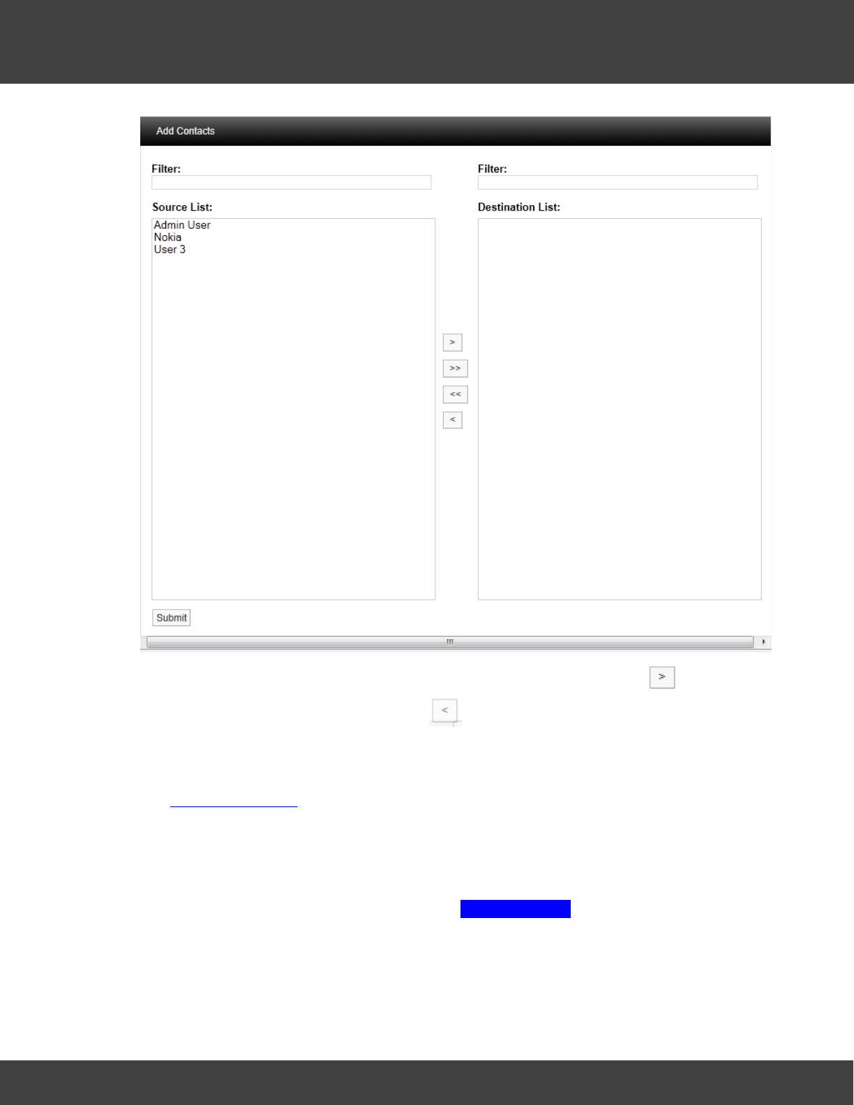
111
Notion Pro © 2017 IMC Group Ltd HP5525 Version 1.2.15
Reference Section
To select a Contact or Contacts highlight the required contacts and select , to de-select
a Contact highlight the Contact and select .
When happy with the details select Submit.
There is an option to have email Alarms sent to non-Notion Pro Users or External Contacts.
See User Management.
To select External Contacts click the External Contacts tab and follow the procedure above
for adding System Contacts.
SMS Alert Group
To access the SMS Alert Group settings select SMS Alert Group from the menu, see below.
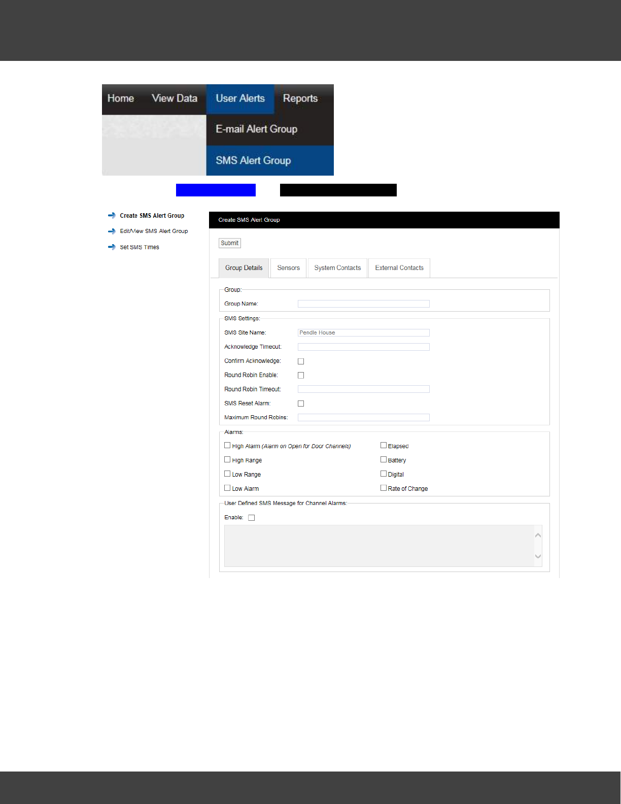
112
Notion Pro © 2017 IMC Group Ltd HP5525 Version 1.2.15
Reference Section
After selecting SMS Alert Group the Create SMS Alert Group window appears, see below.
The window above allows SMS Alert User Groups to be created and configured for the
automated notification of SMS Alarms.
Step 1
Input a Group Name. This can be something that makes sense to the Site in question or
something related to the function. For, example we could call the group, “Service SMS”. This
will be a group that sends SMS Alarms to the Service Engineers.
Step 2
Enter an Acknowledge Timeout. This is the time that the system will wait for an
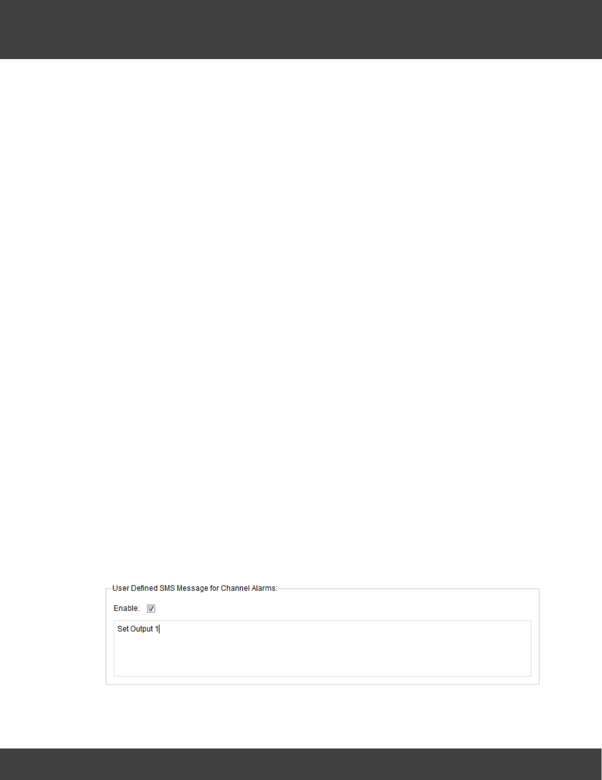
113
Notion Pro © 2017 IMC Group Ltd HP5525 Version 1.2.15
Reference Section
acknowledgement message before re-sending the message. This should be entered in time
format like this: 00:10:00. This would be a 10 minute delay.
Step 3
Select the tick box next to Confirm Acknowledge if an acknowledgement SMS message is
required.
Step 4
SMS Alerts can be sent in "Round Robin" mode. Round Robin mode is when SMS Alerts are
sent to the first name in the list. If there is no response within the time limit the system
moves on to the next person in the list and so on until a response is received. To activate
Round Robin mode select the tick box next to Round Robin Enable.
Step 5
You can select the time period the system waits before sending the next message, this
should be entered in time format like this: 00:15:00. This would be a 15 minute delay.
Step 6
If you require, a Reply SMS can be sent which will reset the Alarms. To activate this feature
select the tick box next to SMS Reset Alarm.
Step 7
The number of times the system will go around the Round Robin loop can be limited. To
activate this feature enter the number of times the system should go round the loop in the
Maximum Round Robins field.
Step 8
Select the Alarm parameters that Email Alerts are required for by clicking in the tick box next
to the Alarm condition within the Alarms panel. Multiple selections can be made.
Step 9
For Channel Alarms, you may define your own text message, (this can be used to trigger
events on a 3rd-party system with SMS receive capability).
To set-up the required message select Enable and enter the required text in the text box.
See below.
Step 10
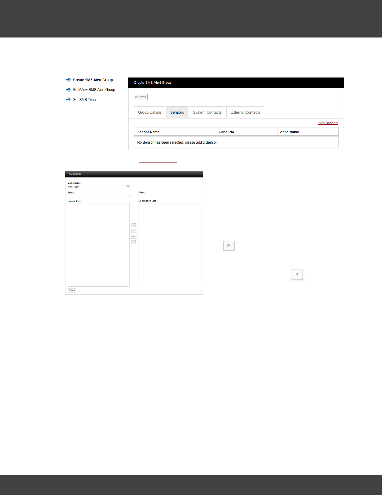
114
Notion Pro © 2017 IMC Group Ltd HP5525 Version 1.2.15
Reference Section
Select the Sensors that you require to be included in the Alert Group. To select sensors click
on the Sensors tab. A new window will appear, see below.
To add sensors click the Add Sensors link, a new window will appear, see below.
To select a Sensor first select a Zone from
the drop down menu.
As the Zone is selected the available
Sensors will populate the left column (Source
List).
To select sensors highlight the ones that
you want to generate email alerts for then
click .
To deselect Sensors highlight them in the
right column and then click .
To move all Sensors across click the double
arrows.
Once happy with you selection select
Submit.
See below for example.
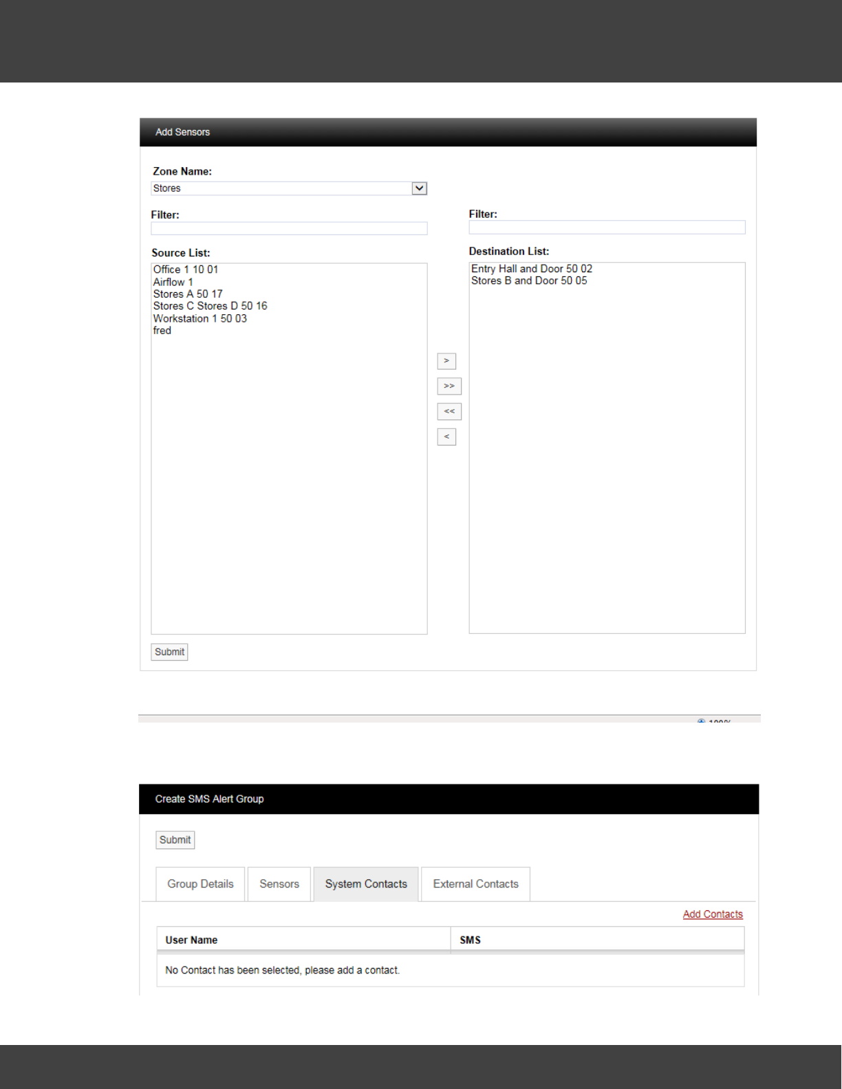
115
Notion Pro © 2017 IMC Group Ltd HP5525 Version 1.2.15
Reference Section
To add Contacts to the Group select the System Contacts tab. A new window will appear,
see below.
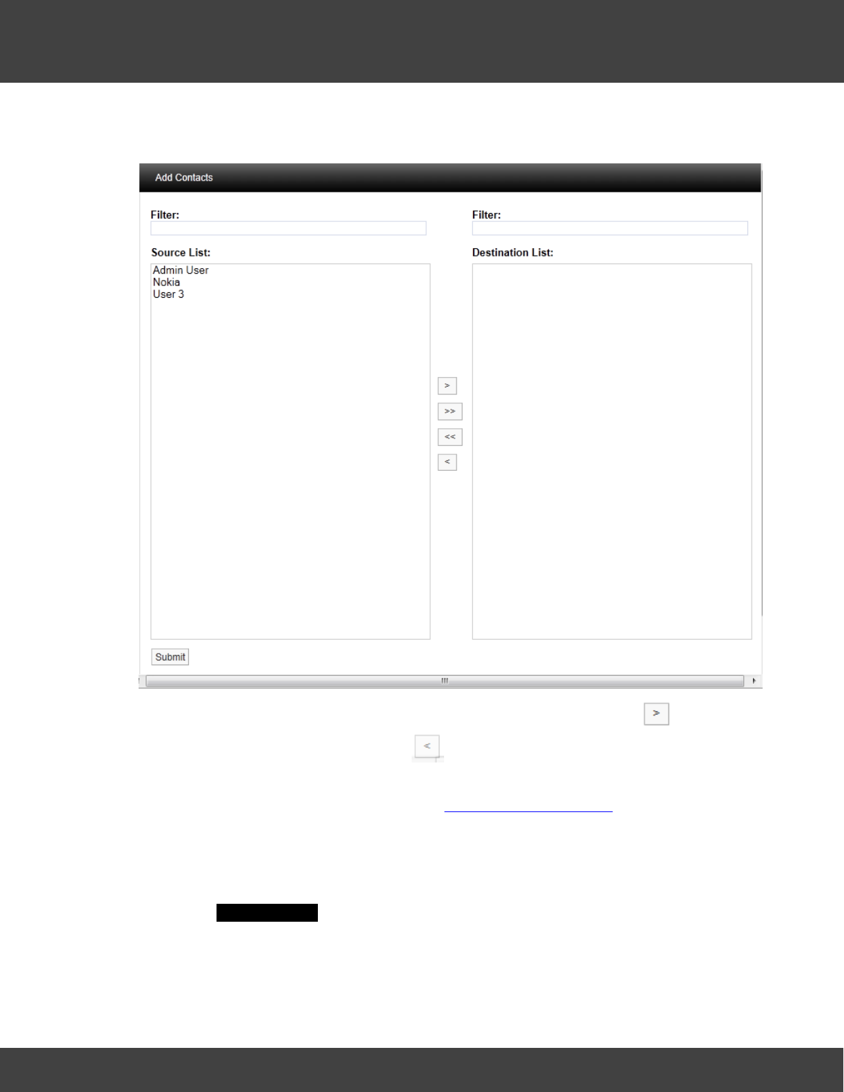
116
Notion Pro © 2017 IMC Group Ltd HP5525 Version 1.2.15
Reference Section
Contacts are the people that you want alerting by email when any of the selected Sensors
are in Alarm. To add Contacts select Add Contacts. A new window will appear see below.
To select a Contact or Contacts highlight the required Contacts and select , to de-select
a Contact highlight the Contact and click . When happy with the details select Submit.
There is an option to have email Alarms sent to non-Notion Pro Users or External Contacts.
To add External Contacts to the system see Create External Contacts.
To select External Contacts follow the procedure above for adding System Contacts.
Set SMS Times
You can set times of day within which SMS messages can be sent. Select Set SMS Times
to give the Set SMS Times dialogue box. See below.
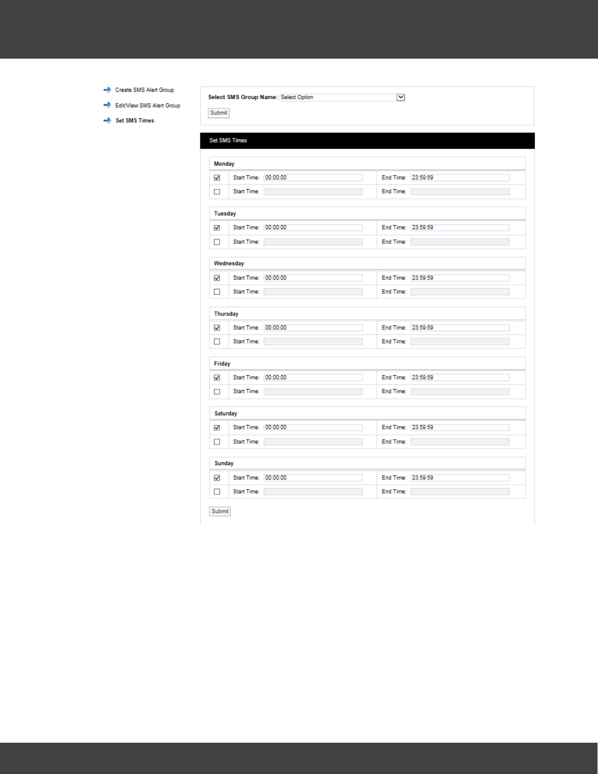
117
Notion Pro © 2017 IMC Group Ltd HP5525 Version 1.2.15
Reference Section
Select the required SMS Alert Group from the Select SMS Group Name pull-down menu.
For each day of the week, select the required Start and End times for SMS messaging. If
necessary, two Start and End time periods can be set within a single 24-hour period.
Enter Start and End times as required, then click Submit.
5.2.6 Site Management
Sites are the main access points to the system data, each Site represents a single physical
Site where receiving devices such as Network Receivers are sited along with measuring
Sensors/Transmitters.
Sites can also have Sub Sites associated with the main top level Site. A Sub Site is used
where it is desirable to sub-divide a main Site, for example when there are large numbers of
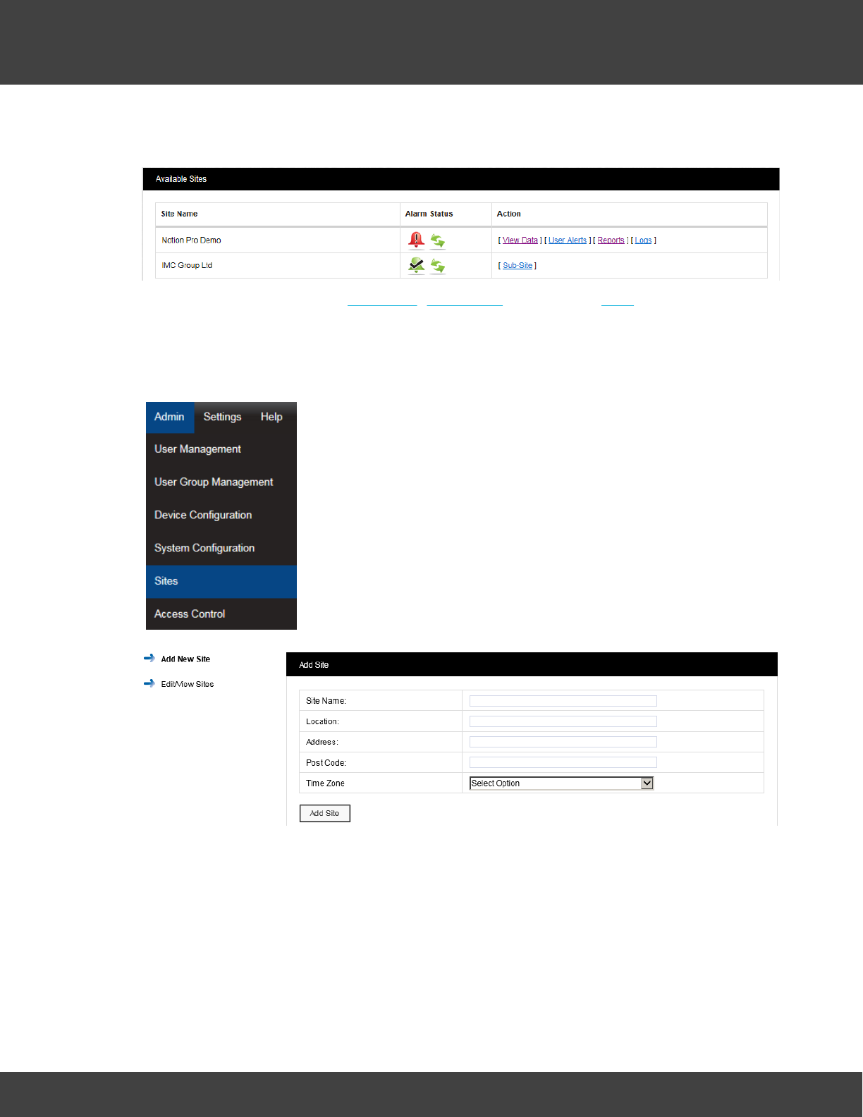
118
Notion Pro © 2017 IMC Group Ltd HP5525 Version 1.2.15
Reference Section
sensors on a Site or many departments. Sub Sites could also be floors in a building or
departments.
When Sub Sites are used the View Data, User Alerts, Reports and Logs are not available
from the top level Site. These functions are now available from the Sub Sites. See below for
details of viewing Site data from the Available Sites dialogue box.
Creating Sites
Select Admin>Sites from the drop down menu to access the Sites
section.
After selecting Sites a new window appears (see below).
To add a Site complete the following:
·Site Name: Enter a name for the Site. For example, this could be the name of the
company.
·Location: Enter the location. For example, this could be the town or city. (not
mandatory)
·Address: This would be the Site address. (not mandatory)
·Post Code: This would be the Site post code. (not mandatory)
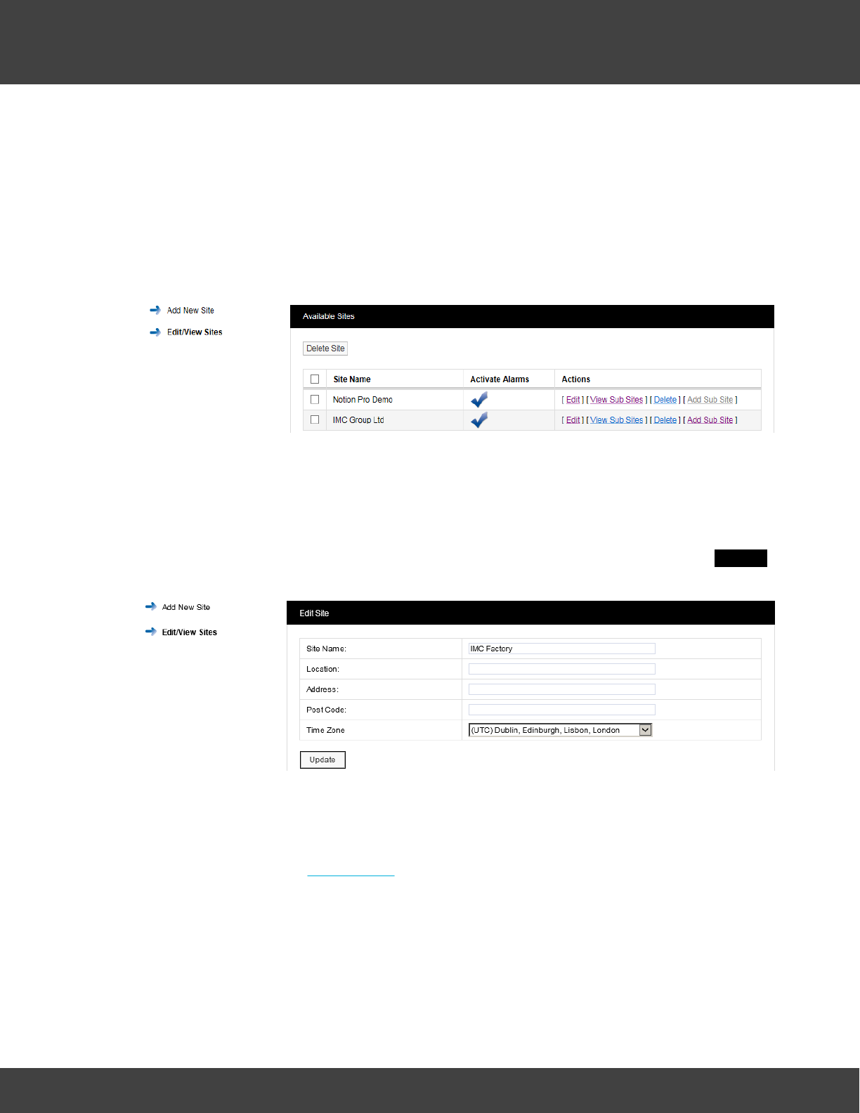
119
Notion Pro © 2017 IMC Group Ltd HP5525 Version 1.2.15
Reference Section
·Time Zone: Set this to the time zone of the Site. (The value displayed by default is the
time zone of the host PC. It is important to set this correctly, as dates in the
database are stored using GMT.)
·When all details have been entered and are correct, click Add Site.
Viewing Sites
To View Sites select Edit/View Sites from the side menu. The Available Sites window
appears. See below.
Note: The Available Sites dialogue box here is for editing Sites and Sub Sites and is
not
same as the Available Sites dialogue box available from the System Overview
selection.
Editing Sites
To edit a Site select Edit on the line corresponding to the Site you wish to edit. The Edit Site
window appears, see below.
All Site details can be edited in this window. When all details are correct select Update to
save details.
Adding Sub Sites
To add Sub Sites select Add Sub Site on the line corresponding to the Site you wish to add
Sub Sites to. The Add Sub Site window appears, see below.
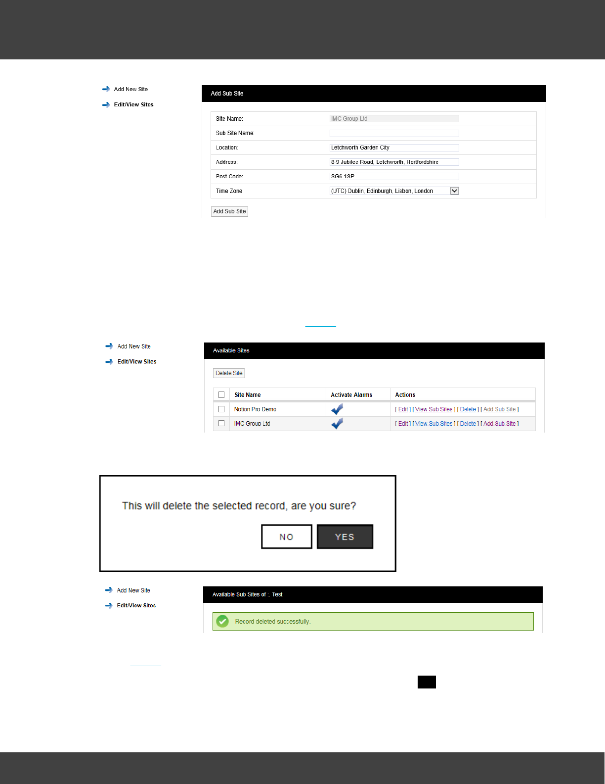
120
Notion Pro © 2017 IMC Group Ltd HP5525 Version 1.2.15
Reference Section
Enter a name for the Sub Site into the Sub Site Name field. When all details are correct
select Add Sub Site to save the details and add the Sub Site.
To return to the main Sites menu select Edit/View Sites from the side menu.
Deleting Sites
To delete a Site you must first delete all Sub Sites if any exist. To check this select Edit/
View Sub Sites. If Sub Sites exist select Delete to delete the Sub Site, see below.
When you are happy that you are deleting the correct Sub Site click Delete and confirm the
deletion, see below.
After deleting all Sub Sites the main site can now be deleted, to delete the required Site
select Delete against the Site to be deleted.
When you are happy that you are deleting the correct Site select YES, see below.
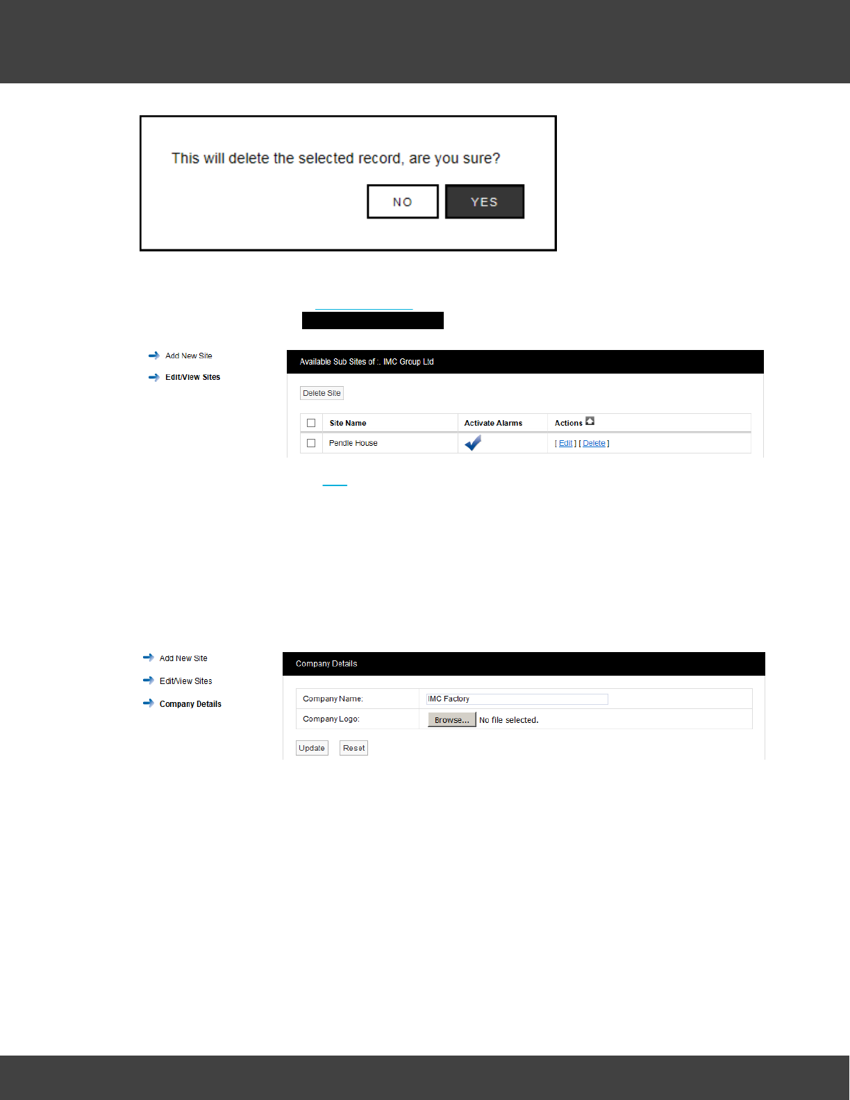
121
Notion Pro © 2017 IMC Group Ltd HP5525 Version 1.2.15
Reference Section
Viewing Sub Sites
To View a Sub Site select View Sub Sites on the line corresponding to the Site you wish to
view Sub Sites for. The Available Sub Sites of window appears, see below.
To Edit the Sub Site select Edit, address details and images can be changed or added.
When happy with any changes select Update.
Adding Company Details
Select Company Details from the menu allows you to add your Company logo. After adding
the details the logo will appear next to Notion Pro logo in the header of the website.
To add your logo, click Choose File navigate to the required logo image, and click Open.
Choose File button varies from browser to browser; in some browsers it might say Browse.
5.2.7 Device Configuration
Warning: Changing settings in this section will impact on system function, please proceed
with caution. If in doubt please contact your local supplier or IMC Support.
This section is where Notion Pro Hardware Devices are setup and configured.
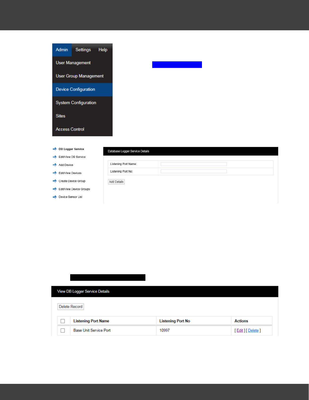
122
Notion Pro © 2017 IMC Group Ltd HP5525 Version 1.2.15
Reference Section
Select Admin>Device Configuration from the drop down
menu to access the Device Configuration section.
After selecting Device Configuration a new window appears (see
below).
Setting up the Database Logger Service
The DB Logger Service is the Service that passes data to the SQL database. The Listening
Port Name and the Listening Port No are set automatically during installation. There is an
option to change this information during installation but it is highly recommended that the
default values are used. If there is a port conflict this should be noted on the Notion Pro
Pre-Requisites Manual (doc. no. IM5546).
Edit/View DB Service
To Edit the Listening Port No select Edit/View DB Service from the menu. A new
window View DB Logger Service Details will appear, see below.
It is possible at some time in the future that a new piece of software could be added to the
server which causes a Port conflict. IMC would recommend that the new item be given a
different Port number. If this is not possible then a new Port number can be allocated to the
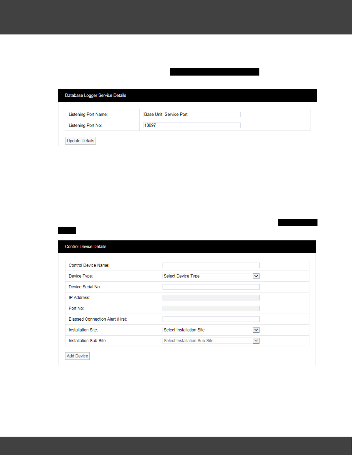
123
Notion Pro © 2017 IMC Group Ltd HP5525 Version 1.2.15
Reference Section
relevant Notion Pro Service.
To Edit the Port number select Edit in the line corresponding to the Service you wish to
change the Port number a new window Database Logger Service Details will appear, see
below.
You will need to contact your IT department or IT service provider to get a new Port
number. Once you have the new Port number enter it into the dialog box next to Listening
Port No. Once you are happy with the details select Update Details.
Warning: The Data Services will need to be re-started after changes are made, and all
Receiver Units , Alarm Units and SMS Units will need to be reconfigured.
Adding Devices
This section describes the addition of wireless receiving devices to Notion Pro. To add
Devices to Notion Pro select Add Device from the side menu. A new window Control Device
Details will appear, see below.
Control Device Name:
This should to be related to Site and location to identify the Device this should be a unique
name across all sites. Example: Network Receiver First Floor Building One. Enter required
text into dialog box next to Control Device Name.

124
Notion Pro © 2017 IMC Group Ltd HP5525 Version 1.2.15
Reference Section
Device Type:
The Device Type is selected from a pre-defined list. Select the Device Type from the drop-
down menu. There is a label on the back of all Receiving Devices that states the Device
Type.
Device Serial No:
This can be found on a label on the back of the device.
Elapsed Connection Alert
An Alert is generated if the specified time period elapses, without the selected device
connecting to the IMC Remote Data service. An entry is recorded in the Activity Log and
the icon in the Available Sites dialogue box (see Site Management) changes to red ( ).
If the Email System Group and/or the SMS System Group has Hardware Event selected,
then an Email and/or SMS will be sent.
Installation Site:
The Installation Site can be selected from the drop-down menu. This list is automatically
populated with Site names added in the Sites section. Select the Site name for the Site that
you are adding the Device to.
Installation Sub-Site:
The Installation Sub-Site can be selected from the drop down menu. This list is automatically
populated with Sub Site names added in the Sites section. Select the Sub Site name for the
Site to which you are adding the Device.
Edit/View Devices
Select the items to Edit when happy with the changes select Update Details.
Create Device Groups
Base Units can receive data from a maximum of 200 transmitters. On systems with more
than 200 transmitters, Device Groups enable specific sensors to be assigned to a Base Unit,
or group of Base Units.
On systems with fewer than 200 transmitters, all sensors are available to be received by all
Base units. However, Base Units still need to be a member of a Device Group.
If you are going to fewer than 200 transmitters and all your Base Units are in a single
location such as a warehouse or a laboratory, then it is probably best to group all your Base
Units in a single group.
If you are going to exceed 200 transmitters then you will need to use multiple Device
Groups; also if you have Base Units at separate physical locations, then using separate
Device Groups can help you manage your system.
To add a Device Group select Create Device Groups from the menu, a new window Create
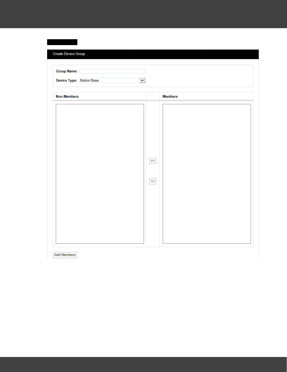
125
Notion Pro © 2017 IMC Group Ltd HP5525 Version 1.2.15
Reference Section
Device Group will appear, see below.
The Group Name should be a name that easily identifies a Device Group, a Group that
contains one or more Receiving Devices. Every receiving device must be in a Device Group.
The Device Type is selected from a drop down menu. Select the Device Type that
corresponds to your Device. The name of the device type is clearly printed on the front of
your device (Base Unit).
Available Devices will be listed in the left column, to select a Device highlight it then click the
double right arrows to move it across to the right column.
Once you are happy that the details are correct select Add Members.
Edit/View Device Groups
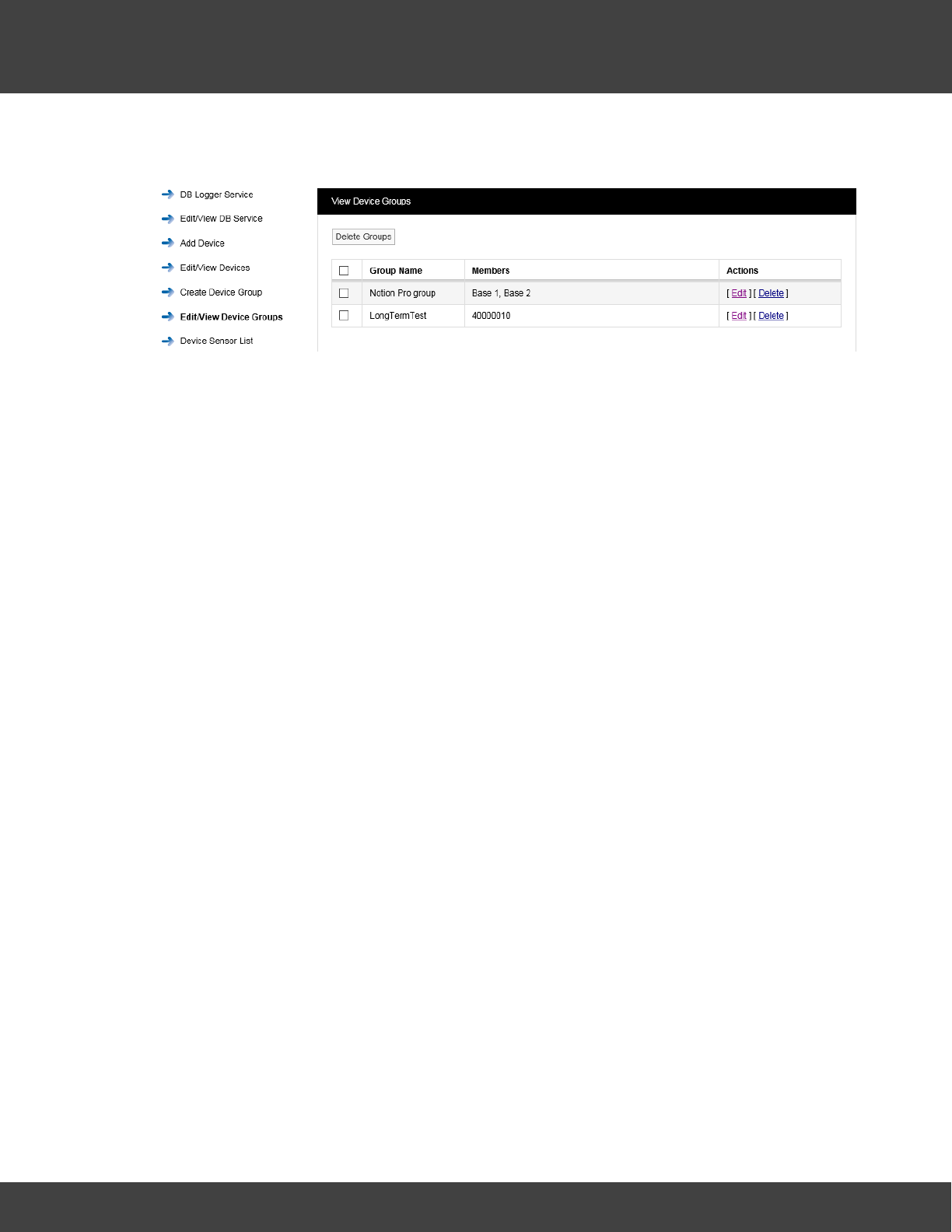
126
Notion Pro © 2017 IMC Group Ltd HP5525 Version 1.2.15
Reference Section
To Edit/View Device Groups select Edit/View Device Groups from the menu to give the View
Device Groups window, see below.
To Edit a Device Group select Edit in the line corresponding to the Group Name that you
wish to Edit, a new window called Edit Device Group will appear, see below.
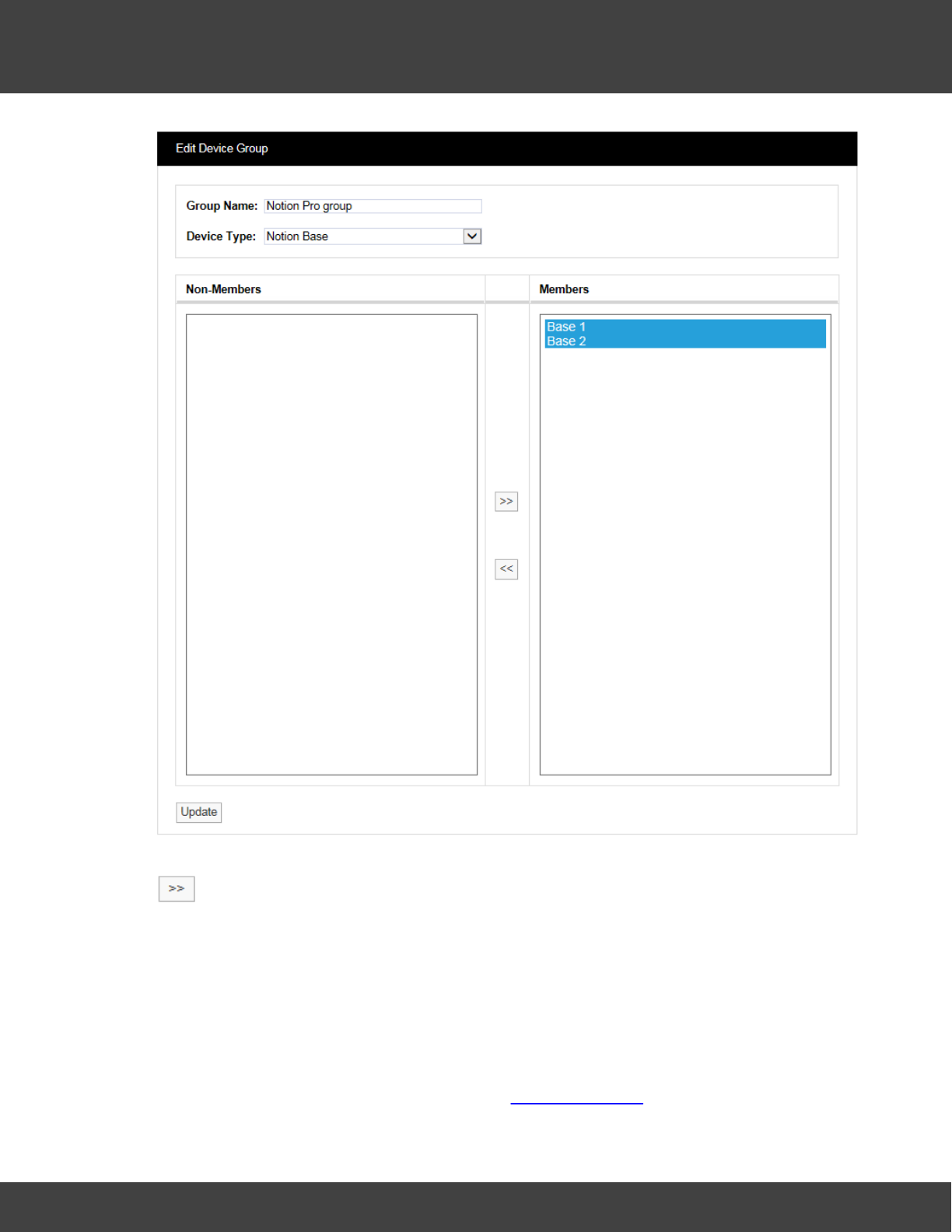
127
Notion Pro © 2017 IMC Group Ltd HP5525 Version 1.2.15
Reference Section
To remove Devices from the Group highlight them in the right hand column then select
. This will deselect them and move them to the left column. You cannot de-select all
Devices from a Group a Group always has to have at least one Device. If you need to
deselect all the Devices then Delete the Group. This can be done by selecting Delete in the
previous step.
Device Sensor Lists
Note: For systems with less than 200 sensors, Device Sensor Lists have no effect.
These list all the sensors associated with a Device Group. The signal from a given sensor
can be received by more than one Base Unit (Network Receiver). You can select a
particular sensor instance (for example, the one with the highest signal strength) and assign
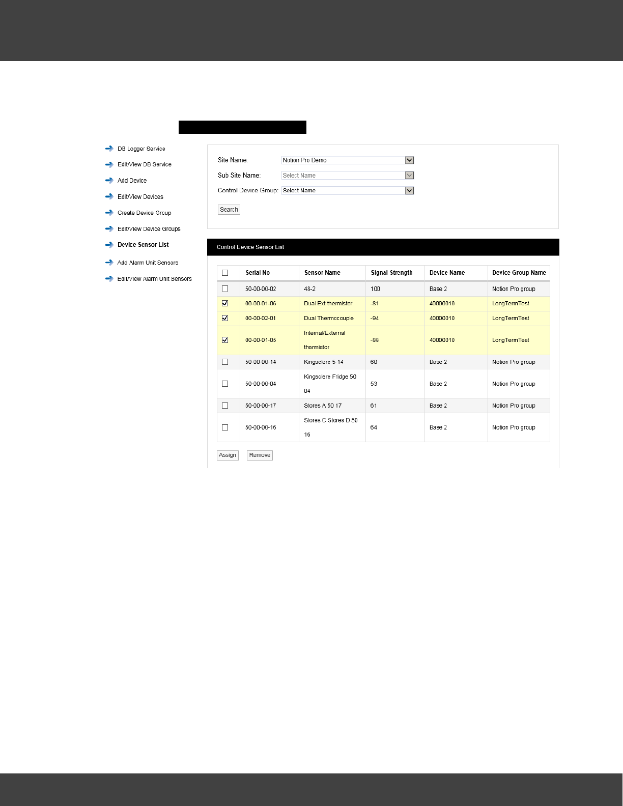
128
Notion Pro © 2017 IMC Group Ltd HP5525 Version 1.2.15
Reference Section
it to the associated device group.
To display a Control Device Sensor List select Device Sensor List from the menu on the
left to give the Control Device Sensor List window, see below.
Note: You cannot create (or delete or edit) a Control Device Sensor List. These are
created by Notion Pro as sensors are added to the System.
Select the Site of interest from the ‘Site Name’ list. You must select a Site. Select the Sub
Site of interest from the ‘Sub Site Name’ list, and the Control Device Group of interest from
the ‘Control Device Group’ list. It is not necessary to specify a Sub Site or a Control Device
Group, in this case a list of sensors for all Sub Sites and Device Groups will be generated (as
in the example above). Click Search to generate the list.
To assign a sensor to its associated Device Group, select the tick box on the left side of the
table, then click Assign. The list will be redisplayed with assigned sensors highlighted. (See
above, three sensors have already been assigned to the ‘LongTermTest’ Device Group).
To remove a sensor from its associated Device Group, select the tick box on the left side of
the table for the sensors you wish to remove, then click Remove. The list will be
redisplayed with assigned sensors highlighted. (In the example above, three sensors have
already been assigned to the ‘LongTermTest’ Device Group).
As another example, the example below shows a case where signals from two sensors (05-
09-00-62 and 05-09-00-46) are each being received by two Network Receivers. The user
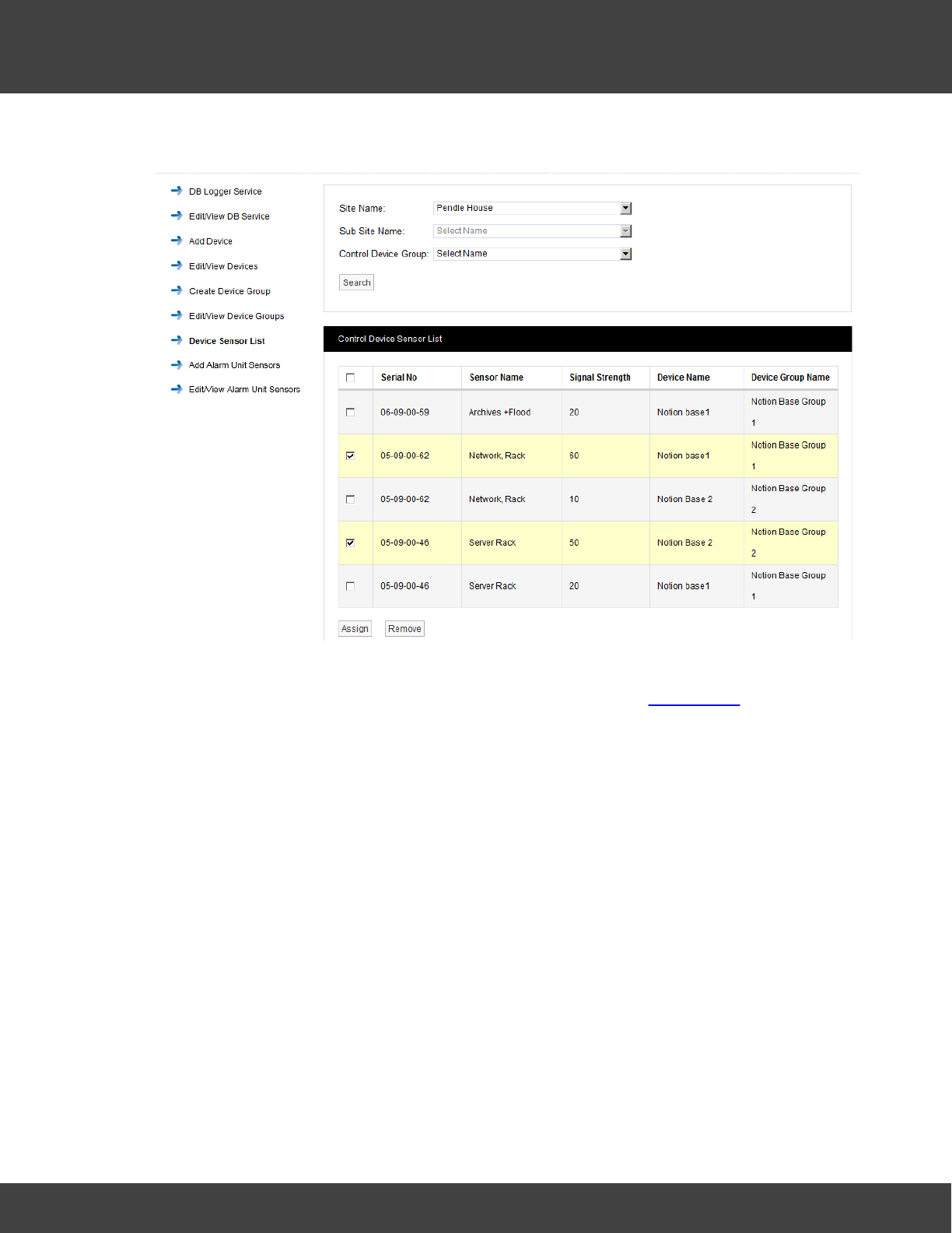
129
Notion Pro © 2017 IMC Group Ltd HP5525 Version 1.2.15
Reference Section
has selected the two sensors with the highest signal strengths to link to a Device Group.
Adding Alarm Unit Sensors
This facility supports the operation of the Notion Alarm Unit (the ARB Module) and enables
you to associate sensors with the unit. Select Add Alarm Unit Sensors from the side
menu, see below.
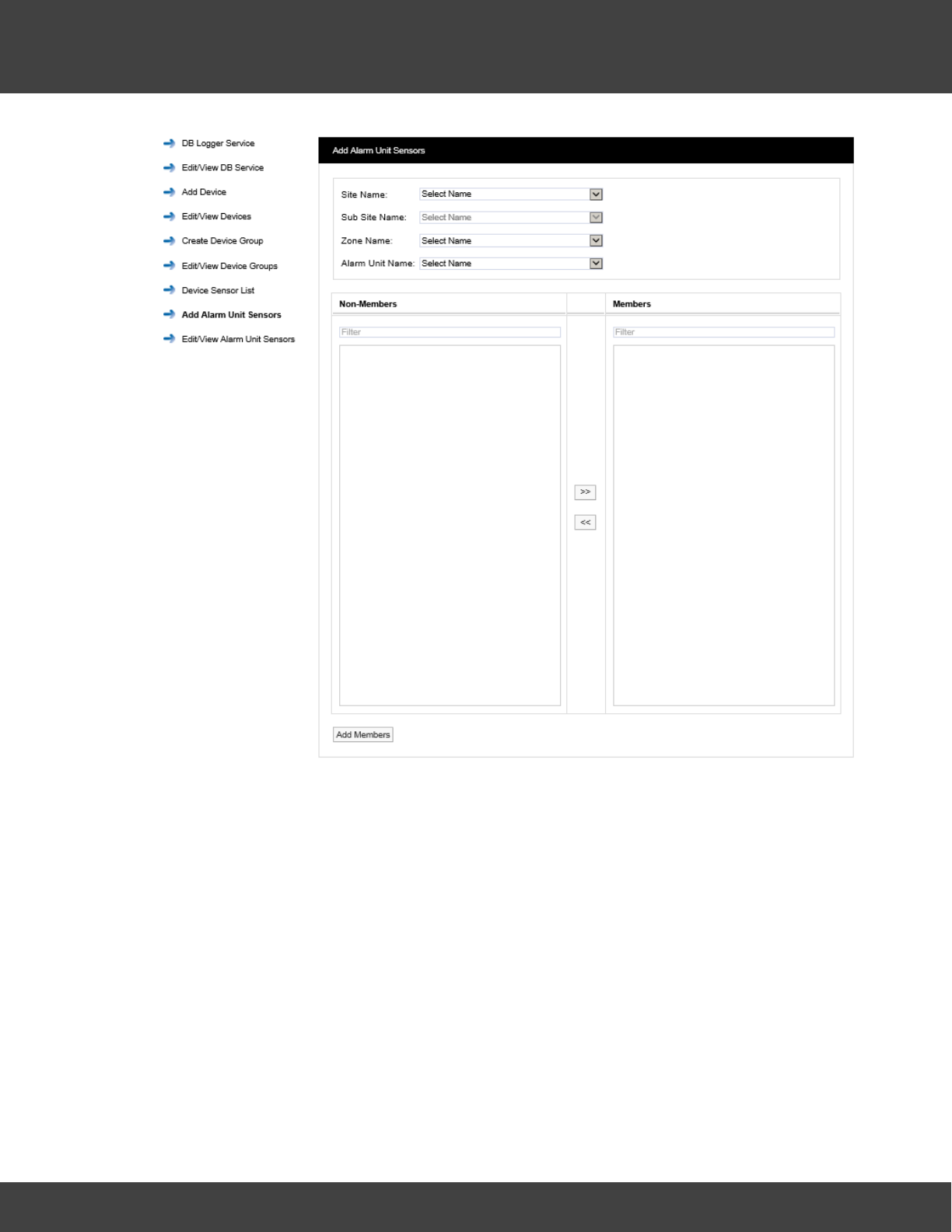
130
Notion Pro © 2017 IMC Group Ltd HP5525 Version 1.2.15
Reference Section
Site Name
Select the Site which contains the Alarm Unit of interest from the pull-down list.
Sub Site Name
Select the Sub Site (if present) which contains the Alarm Unit of interest from the pull-down
list.
Zone Name
Select the Zone which contains the Alarm Unit of interest from the pull-down list.
Alarm Unit Name
Select the Alarm Unit of interest (previously created using the Add Device facility described
at section 2.7.3). The Add Alarm Unit Sensors dialog box changes to show a list of the
sensors which can be associated with the Alarm Unit. See below for example.
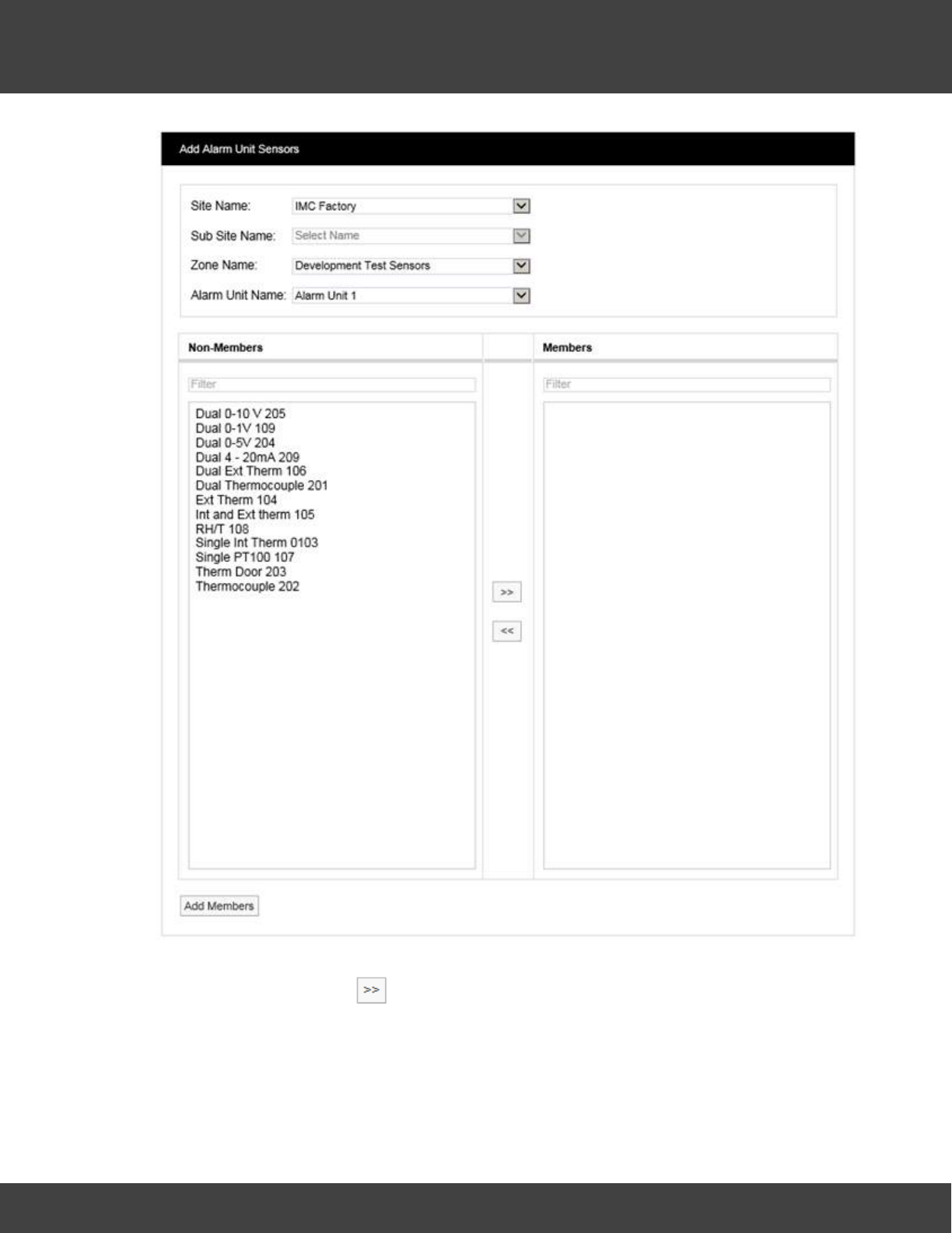
131
Notion Pro © 2017 IMC Group Ltd HP5525 Version 1.2.15
Reference Section
To associate sensors with the Alarm Unit select the required sensors from the Non-
Members list then select to move the selected sensors to the Members list. Click
Add Members to move the selected sensors to the Members list. The View Alarm Unit
Sensors dialogue box will appear to show the sensors which have been associated with the
Alarm Unit. See below for example.
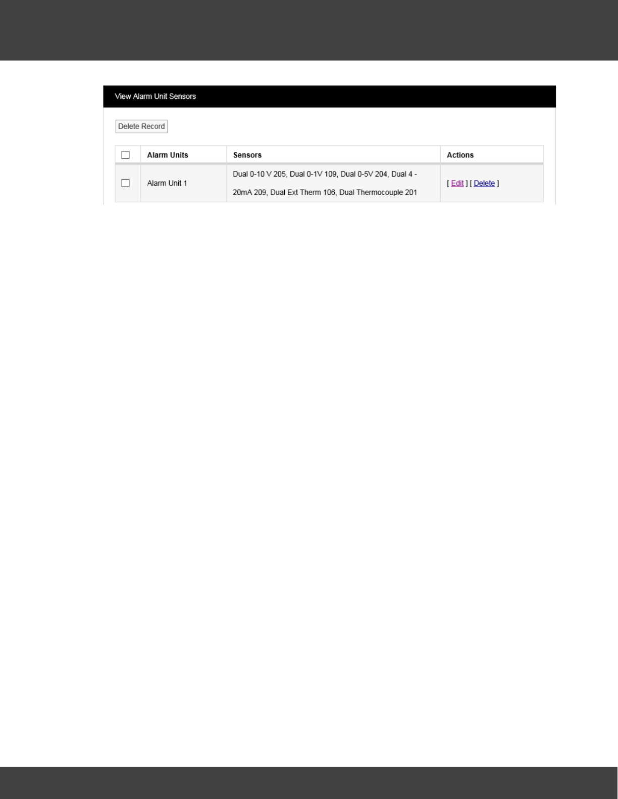
132
Notion Pro © 2017 IMC Group Ltd HP5525 Version 1.2.15
Reference Section
Editing/Viewing Alarm Unit Sensors
To edit or view associated Alarm Unit sensors select Edit/View Alarm Unit Sensors from
the menu to give the View Alarm Unit Sensors window, see above for example.
To the list of sensors associated with a given Alarm Unit, select Edit in the line corresponding
to the Sensor list that you wish to Edit. A new window called Edit Alarm Unit Sensors will
appear, see below.
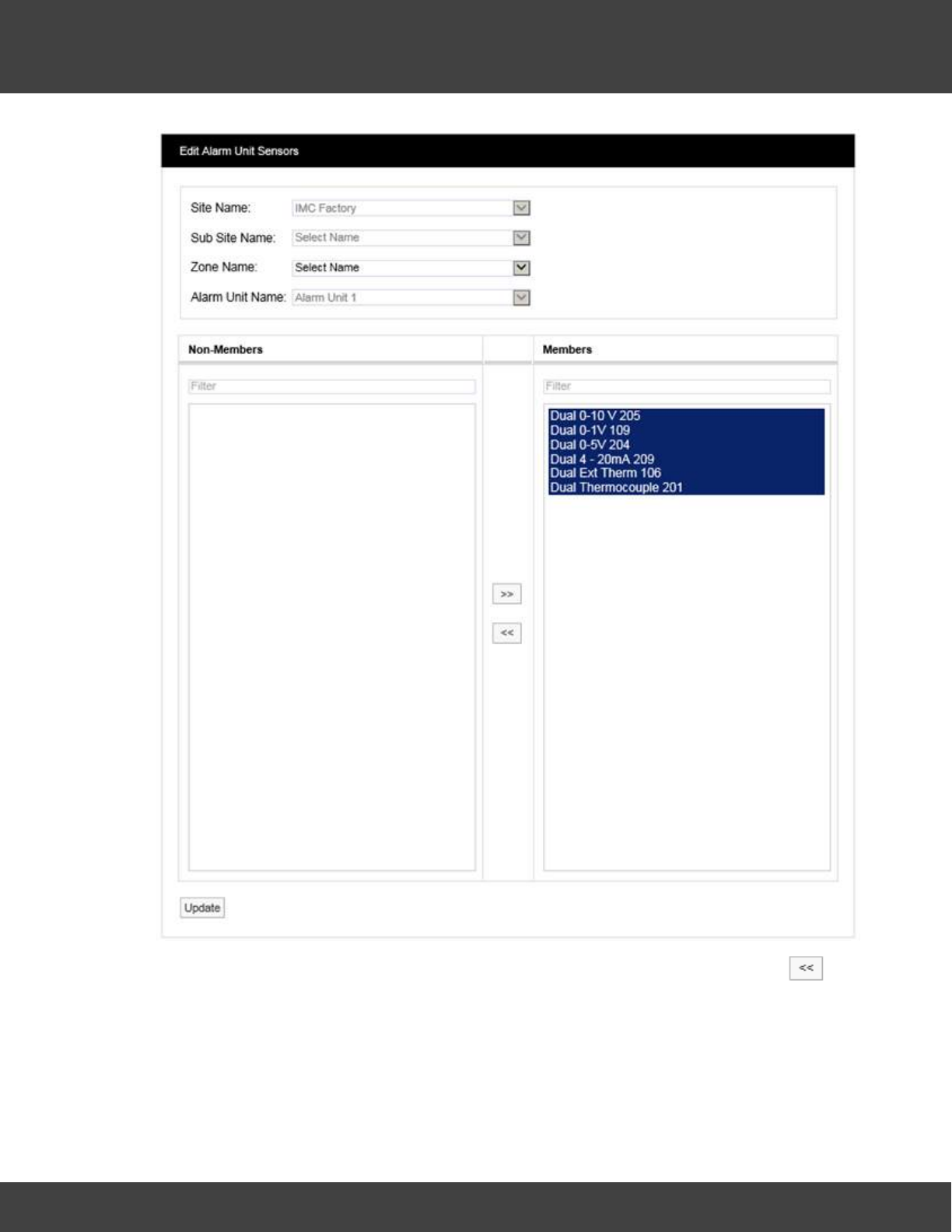
133
Notion Pro © 2017 IMC Group Ltd HP5525 Version 1.2.15
Reference Section
To remove sensors from the list highlight them in the left hand column then select .
The double left arrows will de-select the selected sensor(s) and move them to the left
column. Having de-selected the required sensors click Update to update the list.
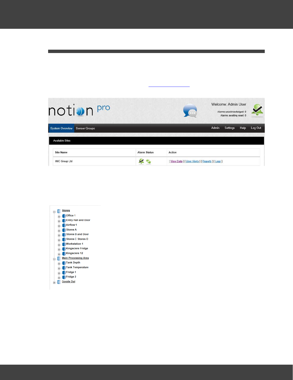
134
Notion Pro © 2017 IMC Group Ltd HP5525 Version 1.2.15
Reference Section
5.3 Setting Up Sensors
This topic gives detailed information on how to add Zones and Sensors to the Notion Pro
System in your Installation.
During the Notion Pro installation process a default Site will have been created. You can Edit
the details for the default Site, see section Site Management. The first time you run Notion
Pro the System Overview screen will look something like:
Before you can start monitoring temperature, humidity and other data you will need to add
some sensors to Notion Pro.
Each main Site can have any number of Sub Sites. Sensors added to a Site can be sub
divided into Zones. Zones are viewed in a familiar Windows-style tree, see below.
Zones allow large systems to be sub-divided into logical groups of
sensors.
Zones can also be used when granting viewing Privileges. When a
Site contains many sensors, just granting Privileges for a whole Site
could still lead to a single User being overloaded with data that
doesn’t relate to that User. Zones can be allocated to Users as well
as Sites.
Individual sensors can’t be allocated Privileges, only Sites and Zones.
There is no practical limit to the number of Zones that can be
added to the system. To allocate an individual sensor to a User add
a Zone for that sensor.
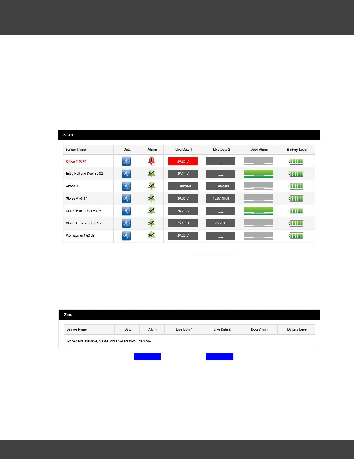
135
Notion Pro © 2017 IMC Group Ltd HP5525 Version 1.2.15
Reference Section
5.3.1 Adding Zones
Zones are used to logically group sensors, this could be all sensors of the same type or all
the sensors in a particular area. For example a Zone could be called RH&T Sensors which
contains all the humidity and temperature sensors, or First Floor Sensors which contains
sensors of different types but which are all on the first floor.
During installation a default Site is created. This Site contains one empty Zone called Zone1.
An example of a Zone which has had Sensors added and which has live data coming
through is shown below.
The above display shows the ‘Stores’ Zone. See Viewing Data for full details of the Live Data
viewing facilities in Notion Pro.
To Edit and add Zones select View Data from the System Overview display for the Site of
interest then View Data>Edit Mode from the main menu bar, see below.
A new window will appear. This window will, as we add Zones and sensors become the main
data viewing and access window, see below (for the default Zone, Zone1).
To add a new Zone select Add Zone from the main View Data menu, see below.
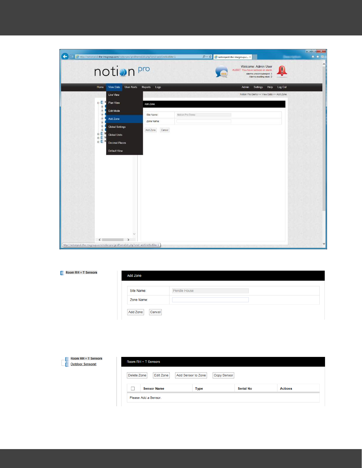
136
Notion Pro © 2017 IMC Group Ltd HP5525 Version 1.2.15
Reference Section
A new window will appear, see below.
To add a new Zone, enter a name into the Zone Name field. For this example we will call
the Zone Outdoor Sensors. When happy select Add Zone. You will now see that another
Zone has appeared in the tree, see below.
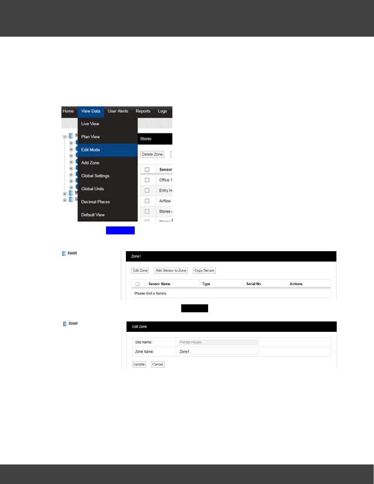
137
Notion Pro © 2017 IMC Group Ltd HP5525 Version 1.2.15
Reference Section
5.3.1.1 Editing Zones
Edit Mode is only available if you have the correct access Permissions. If you do not have
the required access permissions you will see the following message:
Access Denied. You are not authorised to perform this task, please contact your System
Administrator.
After selecting Edit Mode the Sensor and Zone editing/configuration window appears, see
below.
To Edit the Zone select Edit Zone. the Edit Zone window will appear, see below.
Select a name for the Zone that will make it easy to identify either the type of sensors in
the Zone or the location of the Zone. In this example we are changing the Zone1 name to
‘Room RH + T Sensors'. Enter the name into the Zone Name field, once happy select
Update, see below.
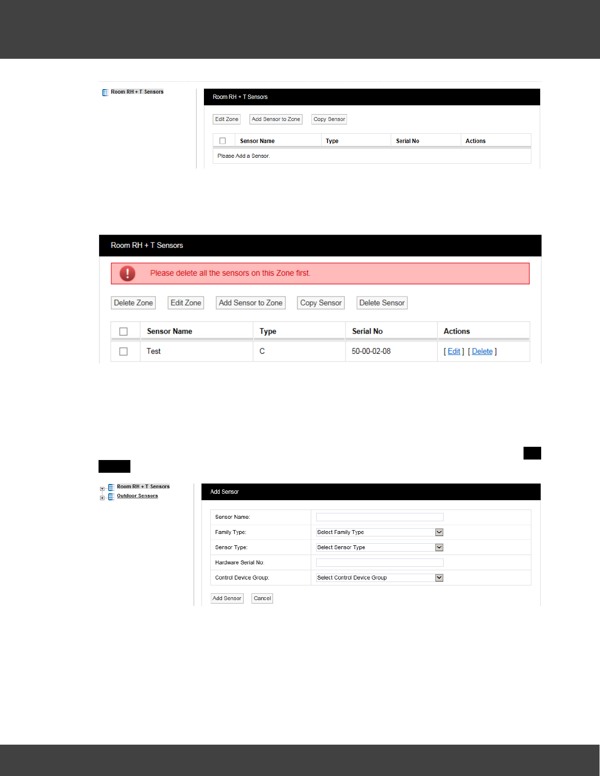
138
Notion Pro © 2017 IMC Group Ltd HP5525 Version 1.2.15
Reference Section
5.3.1.2 Deleting Zones
To delete a Zone select the tick box next to the Zone that you want to delete then select
Delete Zone. You cannot delete a Zone with Sensors still in the Zone, see below.
Delete all sensors in the Zone then repeat the steps above to delete the Zone.
5.3.2 Adding Sensors
Now that we have added some Zones we can now add some Sensors. Before adding
Sensors you need to select the Zone that you wish to add Sensors to. To add Sensors
select View Data>Edit Mode, then select Add Sensor to Zone. A new window called Add
Sensor will appear, see below.
You will notice that the Zone Room RH + T sensors is highlighted (because it is at the top of
the list). This is the Zone that the new Sensor will be added to. If you wish to add a sensor
to another Zone, simply click on the Zone name.
Sensor Name:
Here you can type a name for the Sensor that means something in relation to either the
type of measurement that the Sensor is making or the location, for example, Room 1 RH/
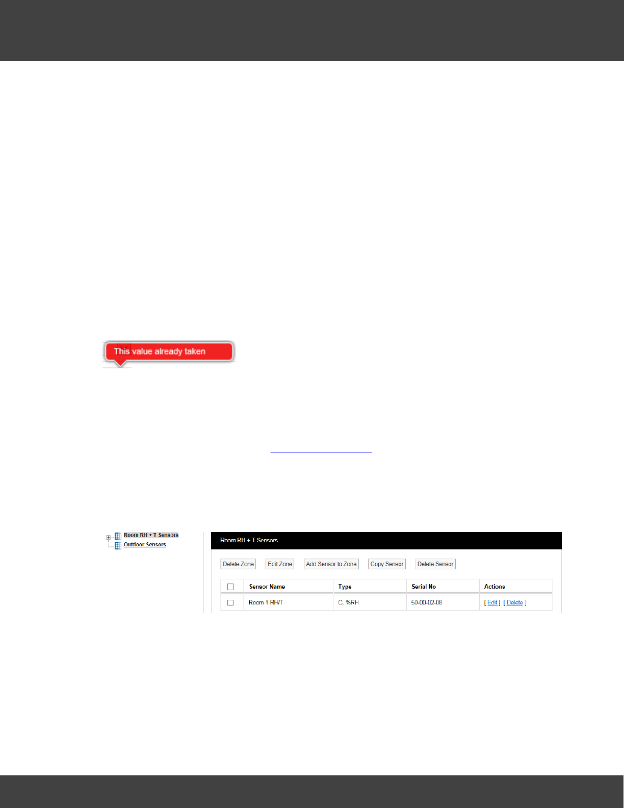
139
Notion Pro © 2017 IMC Group Ltd HP5525 Version 1.2.15
Reference Section
T.
Family Type:
The ‘family’ for the sensor you are adding. Select from iSense, Notion or Legacy / Scout.
Sensor Type:
Select the type of Sensor you are adding from the drop-down menu, a detailed list
explaining all the Sensor types can be found on the IMC Group website.
For this example we will add a temperature sensor, the standard temperature and humidity
sensor can be found in the list as Notion Temperature/RH.
Hardware Serial No:
This is the transmitter serial number and can be found on the back of the transmitter, for
example: 50-00-02-08.
Note: if the sensor has already been added, you would get an error message, as shown in
below:
Control Device Group:
The Control Device Group contains wireless receiving device that will receive the data from
the transmitters. The Control Device Group is selected from the drop down menu, select
the Group that corresponds to the Site and is compatible with the wireless transmitters used
at that Site. For more details see Device Configuration. For this example, we are going to
select Notion Pro Group.
Once you are happy with the details select Add Sensor. You will now see that the Zone
icon has a + symbol to the left of the icon and that the sensor we have just created has
appeared in the table on the right hand side of the screen. See below.
You can add more sensors by repeating the steps above. Multiple sensors of same sensor
type can also be added by selecting Add Multiple Sensors, this feature is useful for
adding sensors in a batch. When adding more sensors additional Zones can also be added
and additional sensors added to those Zones. Sensors can be edited or deleted by selecting
either Edit or Delete in the line corresponding to the sensor to be edited or deleted.
Copy Sensors
Sensors can be copied from on Zone to another. There are cases where you may want to

140
Notion Pro © 2017 IMC Group Ltd HP5525 Version 1.2.15
Reference Section
have the same sensor duplicated in different Zones.
Example 1
When a site has an outdoor sensor it is desirable to have this sensor available in every
Zone. The data from an outdoor sensor can be compared with sensor data from individual
rooms to see if the conditions inside are being driven by the conditions outside. This is a
good indicator of how well HVAC systems (Heating, Ventilating and Air Conditioning) are
performing.
Example 2
Rooms that have many enclosed spaces such as fridges in a hospital or display cases in a
museum can benefit from being able to compare sensor data. A gallery with 20 display
cases all with RH/T sensors could be compared with an RH/T sensor placed in the open
gallery. By comparing the data you can see if the conditions outside are driving the
conditions inside the cases.
To copy sensors, highlight in the Zones list the Zone that you want to copy sensors to then
select Copy Sensor from the Zone dialog box. The Copy Sensors to window appears, see
below. You will notice that the name of the Zone that the sensors are going to be copied to
forms part of the window name.
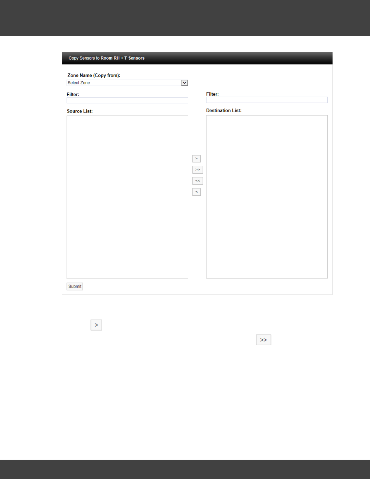
141
Notion Pro © 2017 IMC Group Ltd HP5525 Version 1.2.15
Reference Section
Select the Zone that you want to copy the sensor/s from. The names of the available
sensors in that Zone will appear in the left column. Highlight the sensor/s you wish to copy
then click . This will move the highlighted sensor/s to the column on the right. When
happy with the details select Submit. To copy all the sensors click .
Delete Sensors
There are three methods to delete Sensors:
·Select the tick box to the left of the sensor names that you want to delete on the Zone
dialog box then select Delete Sensor from the top menu. This will delete all highlighted
sensors.
·Select Delete in the row corresponding to the sensor you wish to delete. This will delete
only that sensor.
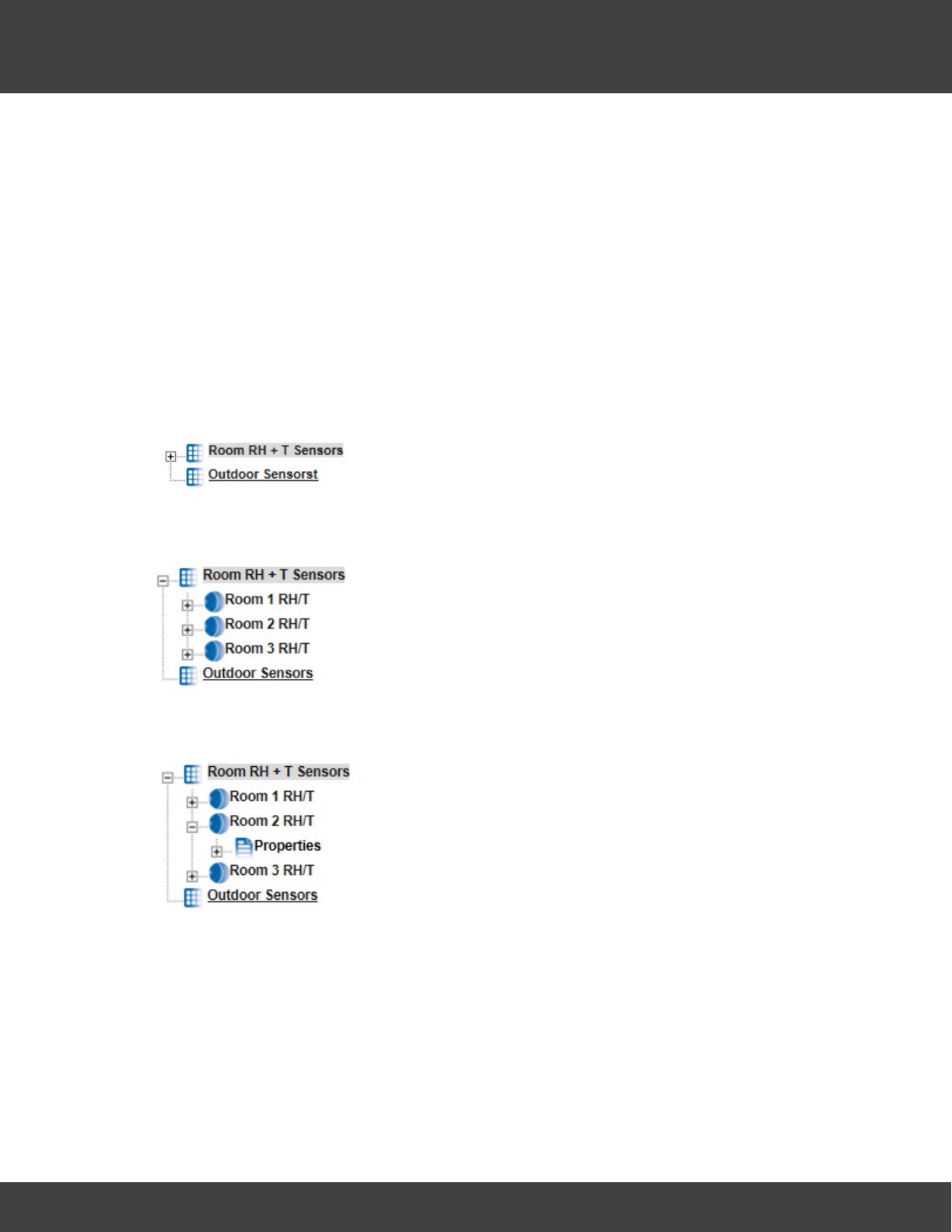
142
Notion Pro © 2017 IMC Group Ltd HP5525 Version 1.2.15
Reference Section
·To delete all sensors in the table, select the tick box on the left of the title row (next to
Sensor Name), then click Delete Sensor.
Warning: Deleting Sensors cannot be undone.
5.3.3 Configuring Sensors
This topic takes you through the configuration of the Sensor properties which include
General Settings, Scale, Alarms and Filters.
Accessing Sensor Properties
To access Sensor properties highlight the Zone name that contains the Sensor that is to be
edited, see below.
To see the available Sensors click on the + symbol next to the highlighted Zone. The
selected branch will expand showing all the available sensors, see below.
To view the properties of the Sensor that is to be edited click on the + symbol next to the
Sensor name. This will expand the branch again, see below.
To access the individual Sensor properties click on the + symbol next to properties this will
expand the branch again, see below.
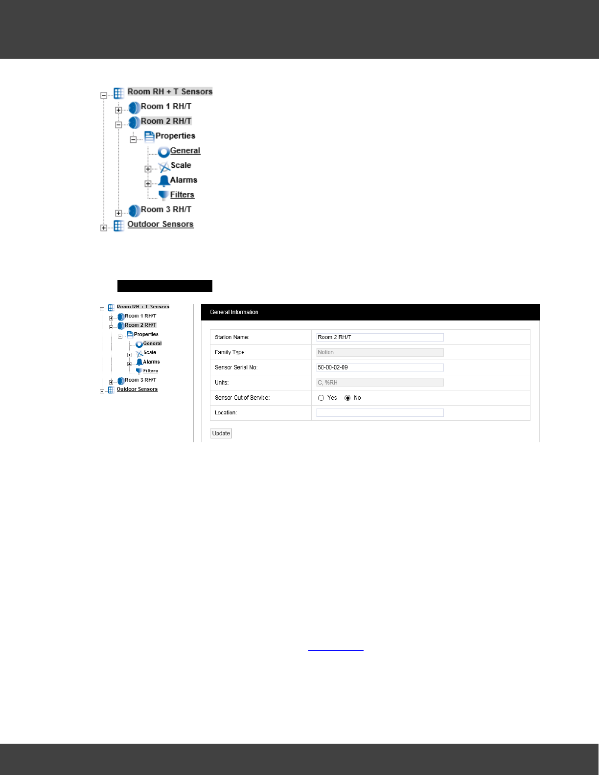
143
Notion Pro © 2017 IMC Group Ltd HP5525 Version 1.2.15
Reference Section
General Properties
To edit the General Sensor Properties click on the underscored link General .This opens
the General Information window, see below.
Station Name:
The Station Name can be changed, be aware that changing the name may be confusing for
other Users as the Station Name normally relates to the physical location of the Sensor.
Changing the Station Name no longer starts a new data file.
Family Type:
Notion.
Sensor Serial No:
This is set when the Sensor is added to the system.
Units:
This is the units for each of the channels for the Sensor. These cannot be changed here as
they are set by the Sensor install. (But see Global Units.)
Sensor Out of Service:
This feature allows you to temporally take a sensor out of service. This is useful if the
Sensor is measuring something that is turned off for a period and monitoring is not required.
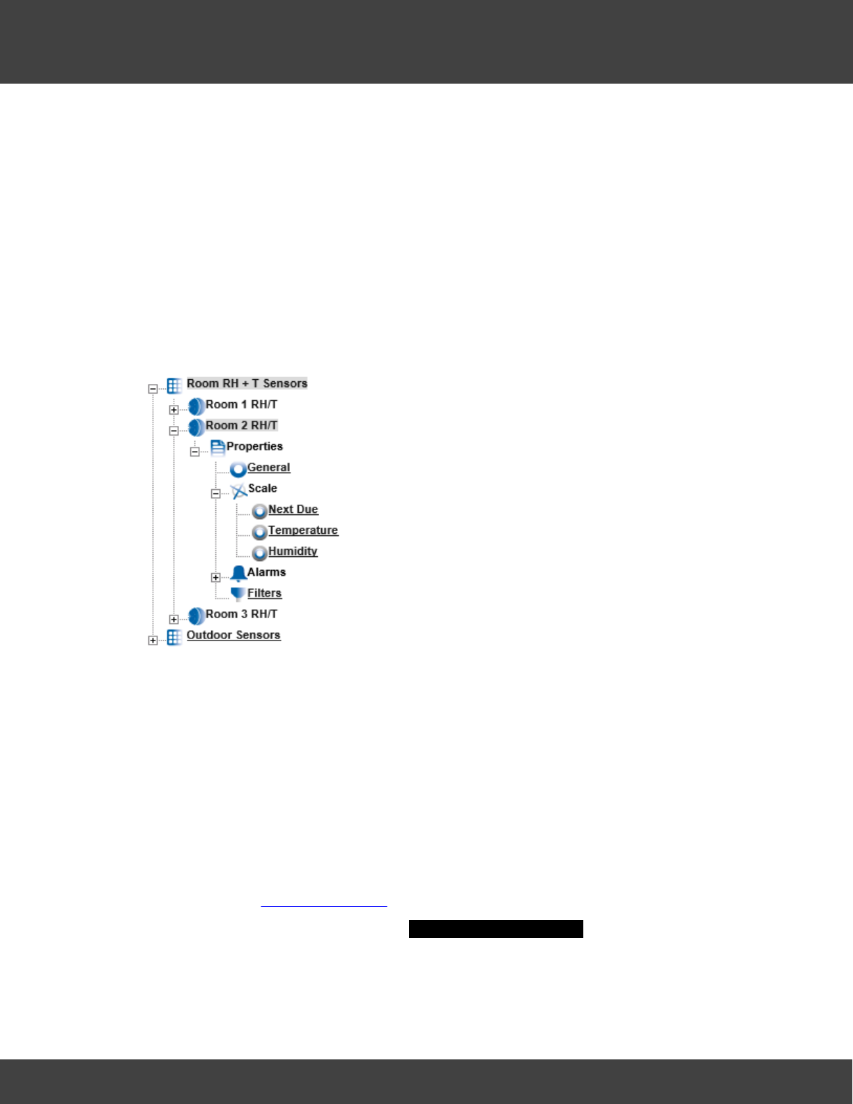
144
Notion Pro © 2017 IMC Group Ltd HP5525 Version 1.2.15
Reference Section
It avoids alarms being generated while the Sensor is not required. Out of Service Sensors
are displayed with blue text in the Live View.
Location:
The Location field allows you to put a note against the sensor to assist with physically
locating the Sensor within a building. This is an aide-mémoire and serves no operational
function within the software and is not mandatory.
Once you are happy with any changes select Update.
Scale
To access Calibration Scale properties click on the + symbol next to Scale and the tree will
be further expanded, see below.
The Scale section allows you to set Graph Scaling, Decimal places and the Next Due
calibration date for Calibration Reports.
If you have iSense Sensors, then this section will allow you to enter the Sensors/
Transmitters to IMC, having IMC Calibration Engineers come to Site or self-correct
calibration parameters for those sensor(s). See the documentation delivered with the iSense
unit for specific calibration details.
Next Due
This feature allows the next Calibration due date to be entered into the system. A PDF
Report can be triggered from the due date field. This is very useful in a regulated
environment where exceeding the stipulated calibration period would cause a non-
compliance. (See Calibration Reports for more information on Calibration Reports.)
To access Next Due click the link, the Next Calibration Due Date windows appear, see
below.
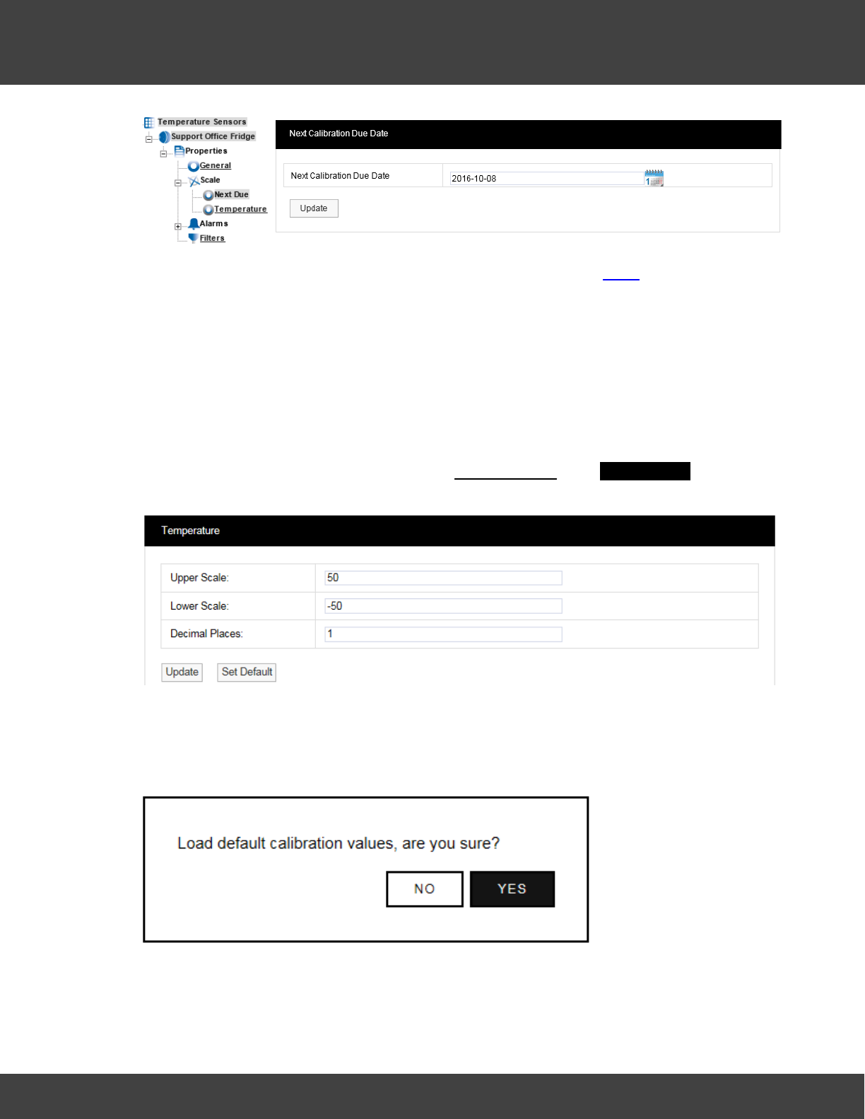
145
Notion Pro © 2017 IMC Group Ltd HP5525 Version 1.2.15
Reference Section
To change the due date enter the new date into the Date field (in LYLY-MM-DD format) or
click on the calendar icon and select the required data. If the Sensor has just been added to
the system the date in the form is one year from the date that the Sensor was added.
A typical period would be 12 months for environments that are contaminated or the
constant operating humidities are very high. Where the environments are clean and the
averages humidities are mid-range then every 24 months would be acceptable.
When you are happy with the new date click Update.
Channel One/Temperature Calibration
To enter the Temperature scale page select Temperature. The Temperature window
appears, see below.
Each Sensor is installed with a default range. These are only a suggestion and can be
changed to suit your requirements.
The defaults can be re-loaded by selecting Set Default,you will be asked to confirm see
below.
Once the new Scale details are known these can be entered into the table above. Select
Update to confirm the details. If correct the following message will be displayed:
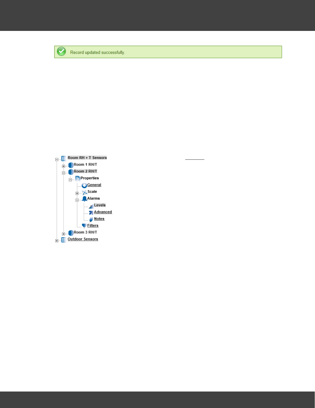
146
Notion Pro © 2017 IMC Group Ltd HP5525 Version 1.2.15
Reference Section
Channel Two/Humidity Scale
To access the Humidity scale settings click Humidity and repeat the steps above.
Note: Not all Sensors/Transmitters have two channels, some have only one.
5.3.4 Setting Alarms
This topic will take you through setting Alarms.
Levels
To access Alarm Settings click on the + symbol next to Alarms (in Edit Mode). This will
expand the branch again, see below.
To access Levels click on Levels. See below.
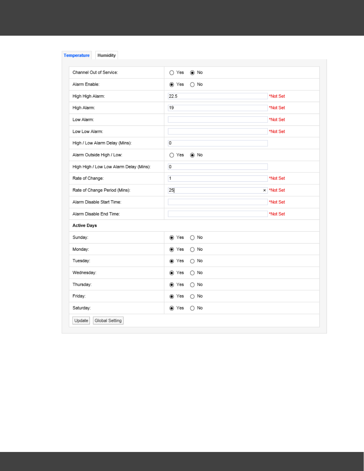
147
Notion Pro © 2017 IMC Group Ltd HP5525 Version 1.2.15
Reference Section
The Sensor in this example is a two-channel temperature and humidity device. You will see
two tabs at the top one marked Temperature and highlighted, the other marked
Humidity. The highlighted tab is the active tab. The tab names will change depending on
sensor type, the number of tabs will change depending on the number of channels.
Channel Out of Service
This feature allows a single channel on a dual channel device to be taken out of service.
This is useful as it may not be desirable to take the whole device out of service for example
if a dual channel temperature transmitter was being used to measure the temperatures in a
fridge freezer and the freezer had failed or was not in use the channel associated with the
freezer could be taken out of service. This would allow alarms from the fridge to come

148
Notion Pro © 2017 IMC Group Ltd HP5525 Version 1.2.15
Reference Section
through the system but there would be no alarms from the unused freezer.
To take a channel out of service select the appropriate tab and select the No option button
to take that channel out of service. When the channel is required again select the Yes
option button.
Alarm Enable
If a Sensor is temporally out of service, or if the alarms are temporally not required rather
than set all the alarm settings to zero the alarms can be disabled. To disable the alarms
select the No option button. When the alarms are required again select the Yes option
button.
High/High High Alarm
The High High Alarm is the highest level alarm that can be set on the system. This alarm
should be set at a level that warns the user of potential damage. (High would represent the
highest point of the desirable working range.) To set the High High Alarm type a value in the
text box next to High High. The level can be set to one decimal place.
Low/Low Low Alarm
The Low Low Alarm is the lowest level alarm that can be set on the system. This alarm
should be set at a level that warns the user of potential damage. (Low would represent the
lowest point of the desirable working range.) To set the Low Low Alarm type a value in the
text box next to Low Low Alarm. The level can be set to one decimal place.
High/Low Alarm Delay (Mins)
The high/low alarms can be delayed, which is very useful to prevent false alarms. In many
buildings rooms are air conditioned to keep the environmental conditions constant. The
conditions in any room change when doors are opened but soon recover when the door is
closed again.
If alarms are set these could be activated every time a door is opened which would
generate many alarms on the system. There is a danger with alarms that a syndrome
called alarm fatigue develops where alarms are generated so frequently that they become
an annoyance and are consequently ignored.
To avoid this a delay in minutes can be set for the alarms. For example when a door is
opened the temperature drops but has recovered back to normal 10 minutes after the door
is closed, without an Alarm Delay an alarm would be generated every time the door is
opened. With an Alarm Delay of 15 minutes there would be no alarm generated however if
the door was left open there would be an alarm generated after 15 minutes. To enter a
High/Low Alarm Delay enter the time in minutes in the text box next to High/Low Alarm
Delay.
Alarm Outside Range
To activate High/Low Alarms click the Yes option button. To disable High/Low Alarms click
the No option button.

149
Notion Pro © 2017 IMC Group Ltd HP5525 Version 1.2.15
Reference Section
High High/Low Low Alarm Delay (Mins)
This feature allows a delay to be activated on the High High and Low Low alarms. It is
generally accepted that no delay is enabled on the High High and Low Low alarms as these
are normally the fail safe alarm levels. If delays are used here it may be that a very small
delay is used to avoid a single reading out of spec generating alarms. To put a delay on the
High High and Low Low alarms type a value in the text box next to High High/Low Low
Alarm Delay (Mins), and should be entered in minutes.
Rate of Change
This feature activates rate of change alarms, depending on the application, a high and low
level alarm may not work. A Rate of Change alarm is a mechanism that monitors how fast a
parameter is changing and generates an alarm based on the selected criteria. For example,
and alarm could be generated if temperature changes by more than 10°C per minute.
To set the Rate of Change enter a value in the dialog box next to Rate of Change. For
example, a value of 10 would mean 10°C per minute if temperature units are set to °C.
(See Global Units for how to set units.)
Rate of Change Period (Mins)
This feature is used together with the Rate of Change value above. Rate of Change Period
is the time period associated with the Rate of Change value. This would be entered in
minutes, so combined with Rate of Change would work like this - if the temperature changed
by more than 10°C in 5 minutes an alarm would be generated. To set the Rate of Change
Period enter a value in the field next to Rate of Change Period (Mins).
Alarm Disable Start Time
This feature allows alarms to be disabled during certain time periods. For example if a room
is used during the day to work on sensitive items, alarms would be required during the day,
but not required during the night. To set the Alarm Disable Start Time enter the time in the
field next to Alarm Disable Start Time and should be entered like this: 18:00:00 in hours, (24
hour clock format) minutes and seconds. All alarms will be disabled after 18:00.
Alarm Disable End Time
This feature works together with Alarm Disable Start Time and sets the reactivation time for
alarms. To set the Alarm Disable End Time enter the time in the dialog box next to Alarm
Disable End Time and should be entered like this: 08:00 in hours, (24 hour clock format)
minutes and seconds. All alarms for this device will be active again after 08:00:00.
Active Days
This feature allows alarms to be turned off on certain days. For example where sensitive
goods are worked on during the week and put away each evening and at the weekend
alarms would not be required at these times. The weekday alarms are handled by Alarm
Disable Start and Stop Times. The weekends can be handled by disabling the alarms on
Saturday and Sunday. To disable alarms on certain days select the No option button. In this
example we want to disable the alarms on Saturday and Sunday. To do this select the No
option button next to Saturday and Sunday. To make those days active again select the
150
Notion Pro © 2017 IMC Group Ltd HP5525 Version 1.2.15
Reference Section
Yes option button.
Once you are happy with your selections click Update. The alarm settings will be saved.
The above can be repeated for the second tab if applicable. After selecting Update and the
settings are saved the settings page returns with a message “Record updated successfully”
see below.
The example dialog box below shows a correctly completed temperature alarm settings
page. The actual values will change depending on the measuring parameters, every
application will be different. The example shows a high level alarm of 25.5°C, a low level
alarm of 5°C with a delay of 5 minutes. The high range is set to 20°C and the low range to
5°C with a delay of 5 minutes.
There is a rate of change alarm active which will alarm if the temperature changes by more
than 10°C in 5 minutes. All alarms are disabled between the hours of 8am and 6pm and
there will be no alarms at any time on Saturdays or Sundays.
Caution:
Alarm fatigue can be a major problem on automated monitoring systems especially when
the alarms can drive emails or SMS alerts to call out service personnel.
There are many circumstances where the conditions of a room or space are not actively
controlled and are driven by outside forces such as what’s happening next door or the
weather outside. In these cases there is little point setting alarms that would relate to ideal
conditions, especially if those conditions couldn’t be met on a daily basis. In these cases it is
better to have no alarms set.
The danger of receiving many alarms that do not have an action where something can be
done to prevent the re-occurrence of that alarm is the main cause of alarm fatigue.
If on the same system there was a critical space with high value objects that was controlled
by an HVAC (Heating Ventilation and Air Conditioning) system, and on system failure an
alarm was generated there is a great danger that this alarm could be ignored.
We are not suggesting that alarms are never set in these conditions just that thought and
consideration are given during the alarm setting process.
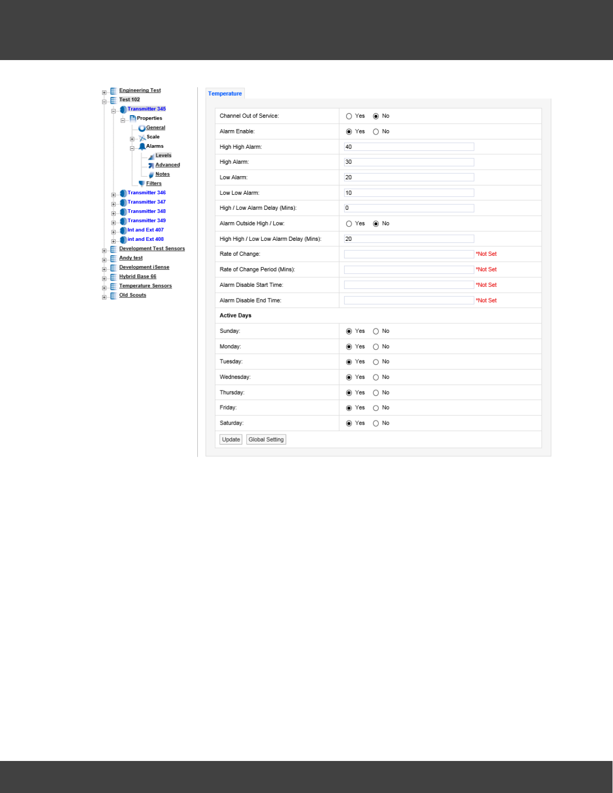
151
Notion Pro © 2017 IMC Group Ltd HP5525 Version 1.2.15
Reference Section
Digital Alarms are Alarms generated by digital channels that record data from devices
such as ‘door open’ sensors. Digital channels can only have two states, which are analogous
to open or closed. The example dialog box below shows the alarm Levels settings view for a
Digital channel:
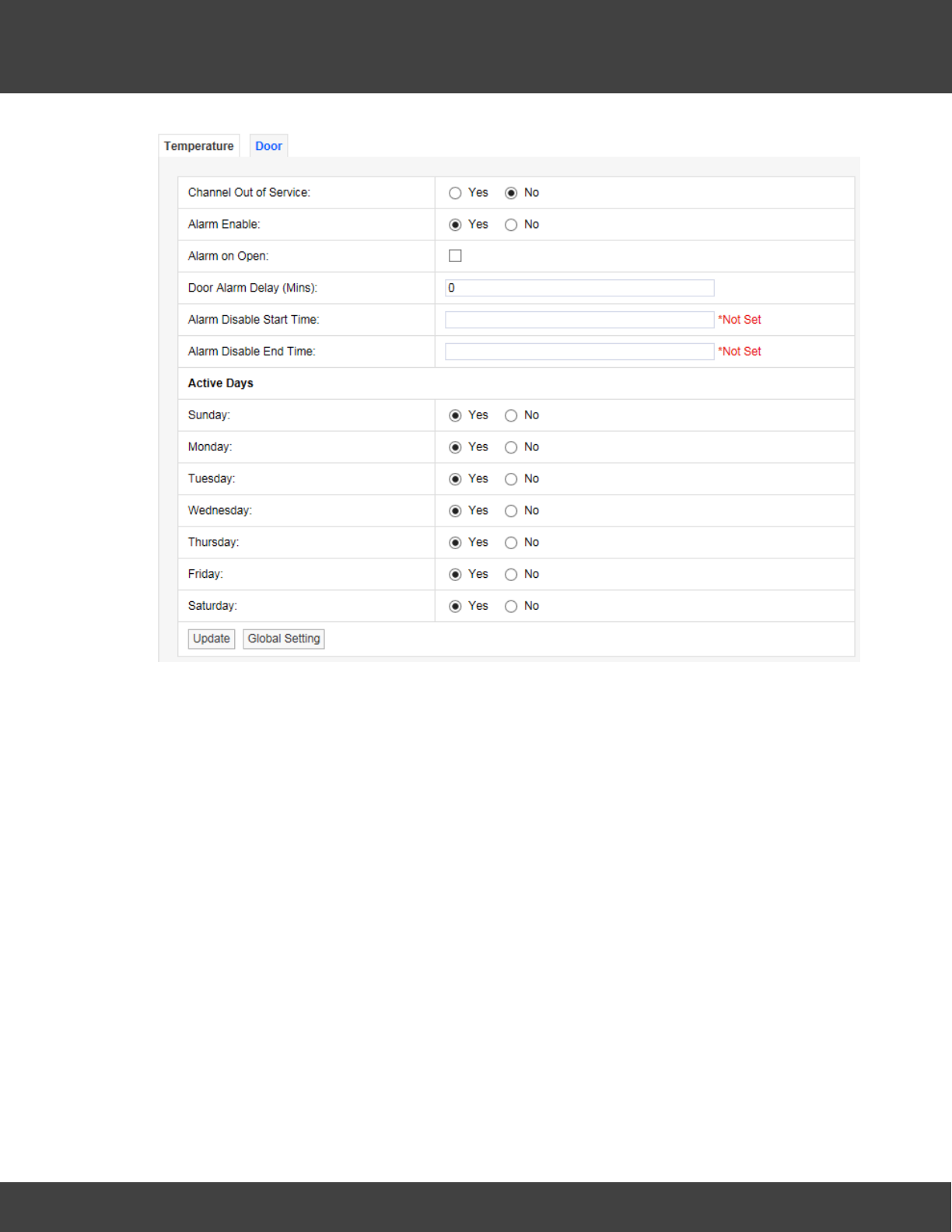
152
Notion Pro © 2017 IMC Group Ltd HP5525 Version 1.2.15
Reference Section
For a door open/close sensor, Alarm on Open would give an alarm if someone opened the
door.
Global Settings
If there are many Sensors/Transmitters on the same system doing the same function in
different spaces it can be tedious and error-prone to go through all the Sensors/
Transmitters on the system. There is a facility to change the Alarm settings globally on a
number of sensors.
To make global changes stay on the alarm settings tab that you want to use to update
other Sensors/Transmitters with and select Global Setting at the bottom of the tab. A new
window will appear, see below.
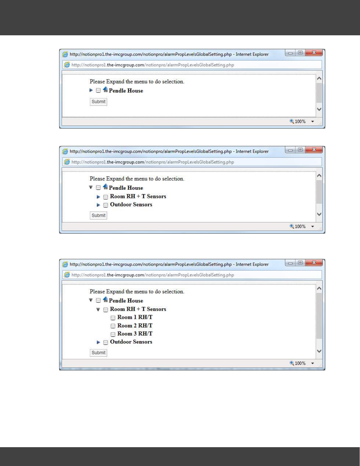
153
Notion Pro © 2017 IMC Group Ltd HP5525 Version 1.2.15
Reference Section
To expand the tree, select the blue arrow to the left of the Site name, see below.
To see the Sensors/Transmitters in a Zone click the blue arrow to the left of the Zone
name, see below.
To select the Sensors/Transmitters to update the alarm settings either click in the tick box
next to the Zone name which will select all the sensors in that Zone or individually select each
sensor in turn by clicking in the tick box next to the Sensor name, see below.
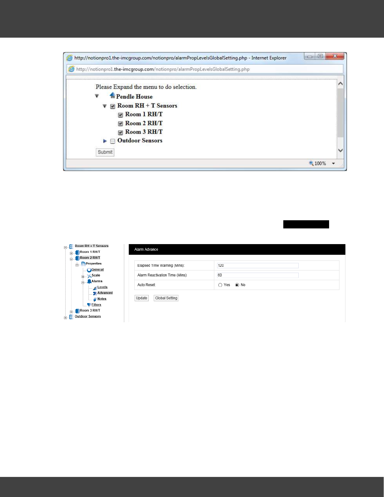
154
Notion Pro © 2017 IMC Group Ltd HP5525 Version 1.2.15
Reference Section
Once you are happy with your Sensor selections select Submit. The selected Sensors will
now be updated with the alarm settings from the selected Sensor. This can be checked by
going into the alarm properties of another Sensor.
Advanced
To edit the Advanced settings select Advanced. A new window called Alarm Advance will
appear, see below.
Elapsed Time Warning (Mins)
The elapsed time warning is used to alarm when a signal is not received from a Sensor
within the predetermined time. In the default settings the Elapsed Time Warning is set to
120 minutes. This can be changed to any time up to 999 minutes. It is not recommended
to set the Elapsed Time Warnings to very long periods. If there are lots of Elapsed Time
Warnings being generated this may be an indication of a more serious problem such as poor
radio coverage.
The main purpose of the Elapsed Time Warning is to alert you that a problem has occurred
such as a Sensor has failed, been moved out of radio range or has inadvertently had the
battery removed.
There are occasions where all the sensors in a Zone or Zones that are served by a wireless
receiving device go into Elapsed Time Warning at the same time. This would be caused by
either a failure in the wireless receiving device or a network problem causing the wireless
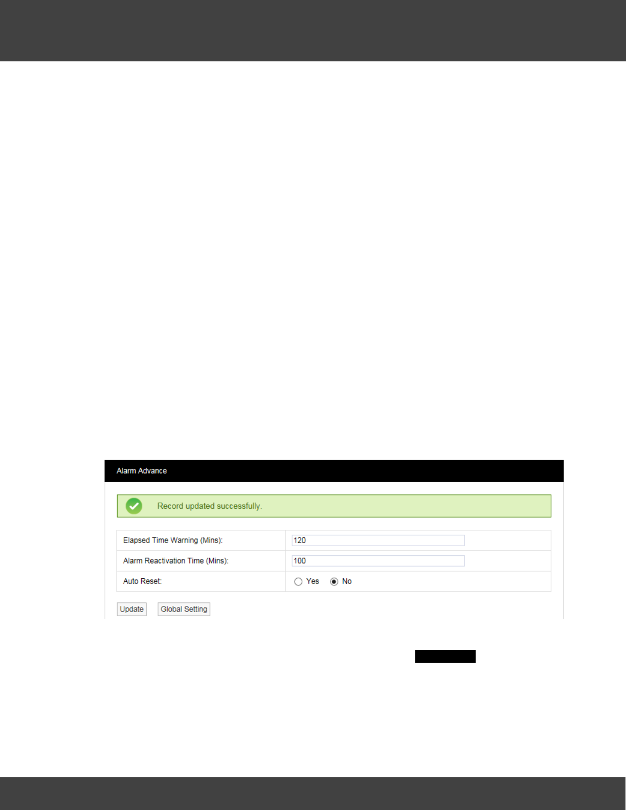
155
Notion Pro © 2017 IMC Group Ltd HP5525 Version 1.2.15
Reference Section
receiving device to stop communication with the database. If such problems are seen then
these need to be investigated.
To set the Elapsed Time Warning period enter the required time in minutes into the field
next to Elapsed Time Warning.
Alarm Reactivation Time (Mins)
The Alarm Reactivation Time is the default setting for the time between acknowledging an
alarm and when the system checks to see if the alarm condition has returned to normal.
If the alarm condition has returned to normal the alarm status will change from amber
(acknowledged) to green (OK), if after the Alarm Reactivation Time the alarm condition still
exists the alarm status will return to red (unacknowledged) and create a new alarm on the
system.
The default setting is 60 minutes. To change this enter a new value in minutes in the field
next to Alarm Reactivation Time.
Auto Reset
Auto Reset is used to reset an alarm status to green when an alarm condition returns to
normal. The default is No which means that all alarms have to be acknowledged. The
disadvantage is that a Sensor could go in and out of alarm all night but when the User
checks in the morning the status shows green, so without looking at the graphs or alarm
logs they would be unaware of a problem.
To change the setting select one of the Yes or No option buttons as required.
When happy with the settings click Update. The setting will be saved, see below.
Notes
To edit the Notes settings select Notes. A new window called Alarm Notes appears, see
below.
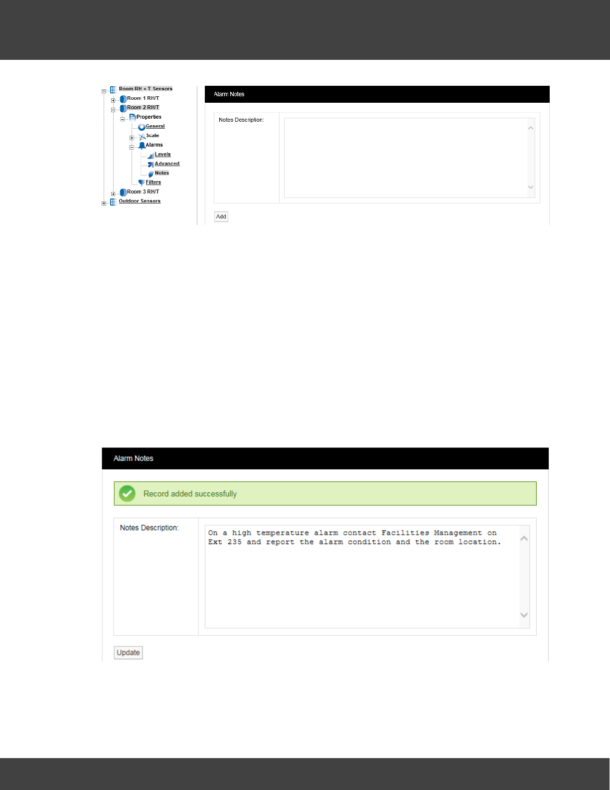
156
Notion Pro © 2017 IMC Group Ltd HP5525 Version 1.2.15
Reference Section
This feature allows you to enter notes for an Alarm. This is especially useful for
inexperienced operators. The system can be set up so that low-level users can monitor the
system but can’t make changes. The Alarm Notes will give an inexperienced user specific
instruction on what to do when an Alarm occurs.
For example in the middle of the night the temperature increases in a room or space
containing high value objects, an Alarm is generated and a night shift operative or security
guard views the Alarm. The Alarm message might say “On a high temperature alarm
contact Facilities Management on Ext 235 and report the alarm condition and the room
location”. This feature means that someone not familiar with an area or its contents can still
effectively and efficiently deal with an alarm condition.
To activate this feature type your instruction into the dialog box and when happy select
Add. This will add the message to this Sensor. This can be set individually for every Sensor
on the system. Once the changes have been added and are OK you will see the following
window, see below.
Filters
This feature lets you set filter limits for the Sensor. These should only be used in exceptional
circumstances. For example if a Sensor is located in or near an electrical switch panel which
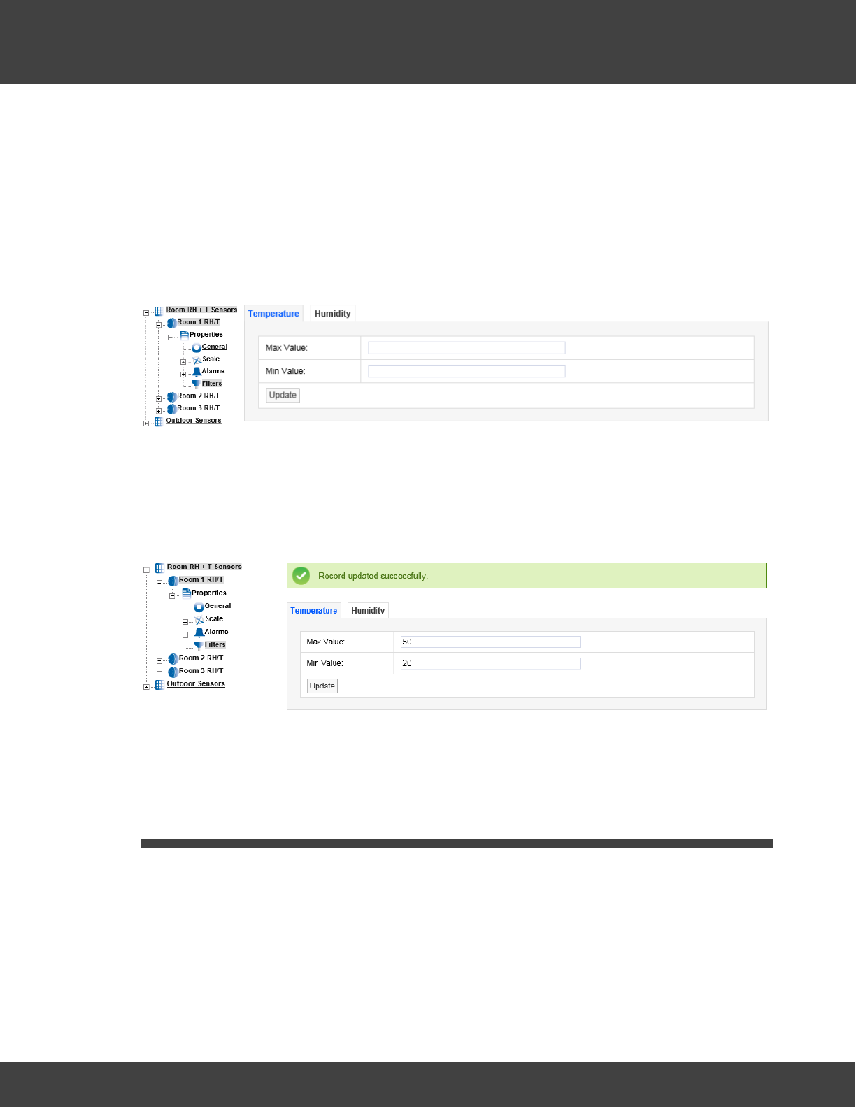
157
Notion Pro © 2017 IMC Group Ltd HP5525 Version 1.2.15
Reference Section
can be very noisy electrically this can occasionally cause interference on the radio link, which
would be seen on the graph as a large spike in the data.
The filters are designed to remove such interference. If the Sensor is reading temperature
and the expected range for this application is -10°C to +50°C a filter could be set at say -
40°C for the Min Value and +80°C for the Max Value. Any readings seen above or below
these readings would be rejected.
To edit the Filter settings select Filters. The Temperature tab (for temperature in this
case) will appear, see below.
To activate this feature enter the required Min and Max values in the appropriate fields. The
values should be whole numbers in the range 50 for the Max Value and -40 for the Min
Value. Select Update when finished. (A warning message is given if you click on another tab
before you’ve selected Update for a change you made on the current tab.) Once the data
is accepted you will see the following screen, see below.
For dual channel Sensors, repeat the above process for the other channel.
Note: Setting filters will cause data to be rejected above and below the filter limits. Check
that any filter limits set are above and below the expected ranges.
5.4 Setting Up Sensor Groups
Notion Pro has the capability to group sensors of the same time together into Sensor
Groups. The Sensor Groups feature is extremely useful for grouping sensors of the same
time that are measuring the same parameters. Sensors from different Sites can be added
to one Sensor Group.
Sensor Groups are also used to control Network Receiver Alarm Relays, SMS Module Alarm
Relays, and associated MS1000 Control Interface outputs via the Local Alarms settings.
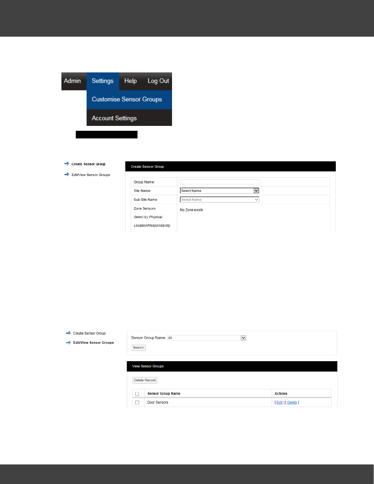
158
Notion Pro © 2017 IMC Group Ltd HP5525 Version 1.2.15
Reference Section
To create a Sensor Group select Settings>Customise Sensor Groups from the main
menu, see below.
The Create Sensor Group window appears, see Creating Sensor Groups
5.4.1 Creating Sensor Groups
Enter a name for the Group this could be “Door Sensors” . Select the Site from the drop
down menu next to Site Name. For this example we will select Notion Pro Demo. If the
selected Site contains Sub Sites, these can be selected from the Sub Site Name drop down
menu.
After selecting the Site the available Zones on that Site become visible, select the + symbol
next to the Zone name that contains the Sensors that you wish to select. Here we will select
the sensors which have a door channel.
Once you are happy with your selections select Create Group. The View Sensor Groups
window appears, see below.
This list contains all the Sensor Groups that are available. Each Sensor Group can be Edited
or Deleted.
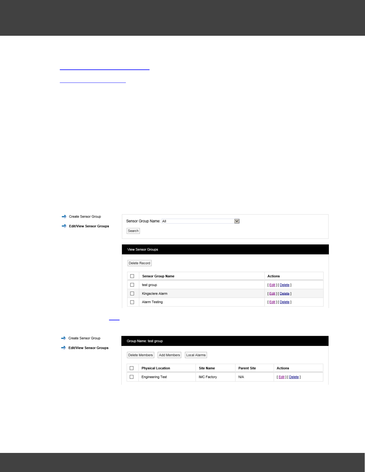
159
Notion Pro © 2017 IMC Group Ltd HP5525 Version 1.2.15
Reference Section
See also:
Create and Edit Sensor Groups
Viewing Sensor Groups
5.4.2 Local Alarms
Sensor Groups are used to control Local Alarms which drive the alarm relays on Network
Receiver, Alarm Unit and SMS Unit devices. If an alarm is activated for a Sensor that is a
member of the Sensor Group, then the associated Local Alarm will be activated on the
device.
Setting up Local Alarms
Firstly create a Sensor Group, adding the required Sensors.
Once the required Sensor group is created, select Edit/View Sensor Group in the left
hand menu, see below for example.
Now click on the Edit action for the new Sensor Group. The edit view will be displayed, see
below.
Click the Local Alarms button to display the Local Alarms view, see below.
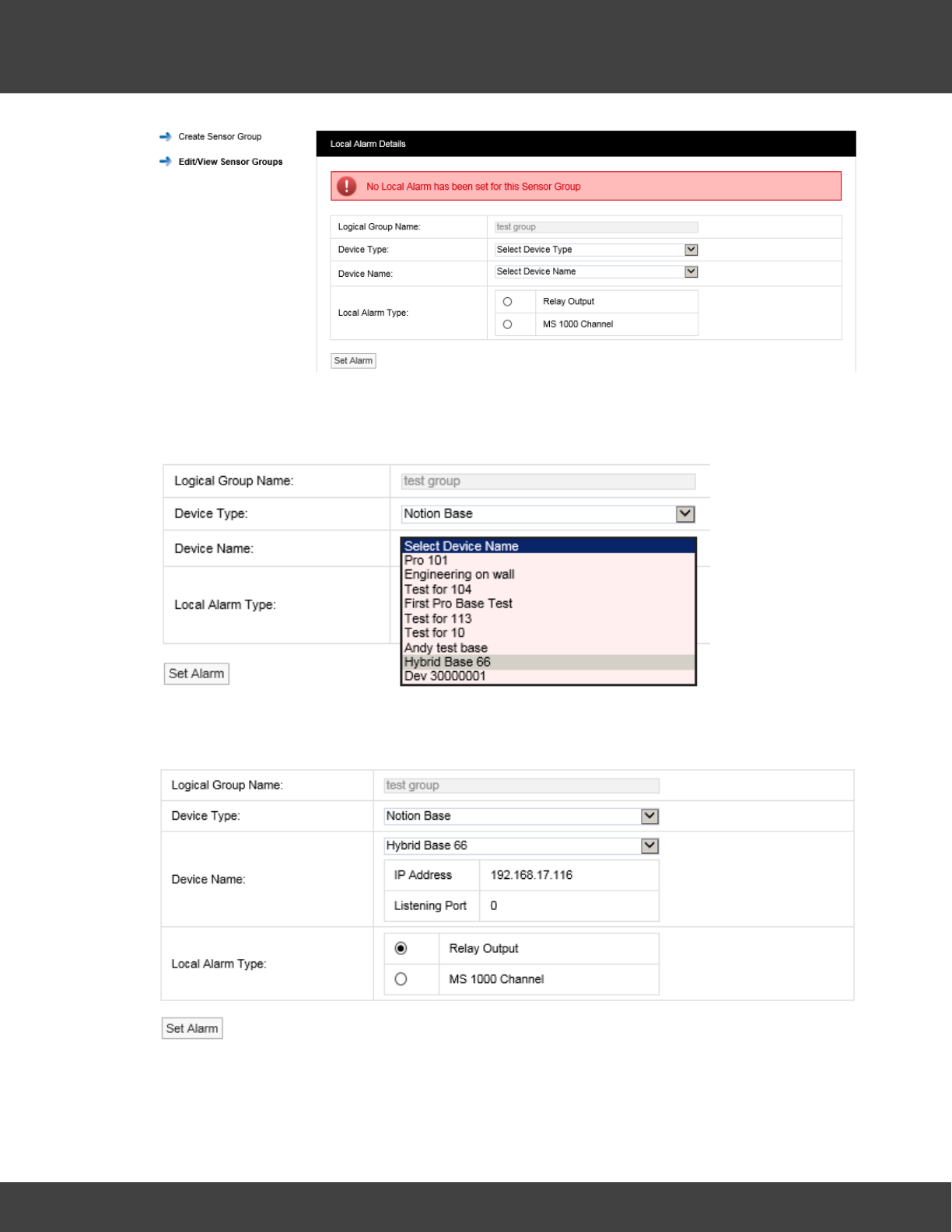
160
Notion Pro © 2017 IMC Group Ltd HP5525 Version 1.2.15
Reference Section
Click on the Device Type combo control, and select the required control device type –
Notion Base [Receiver Unit], IMC Alarm Unit or IMC SMS Unit, see below, then click on the
Device Name combo control and select the require device by name.
The view will now change to display device information and Local Alarm options, see below
for example.
To use the Relay output, select the Relay Output option button.
If you wish to use an output on a MS1000 card; select the option button adjacent to the
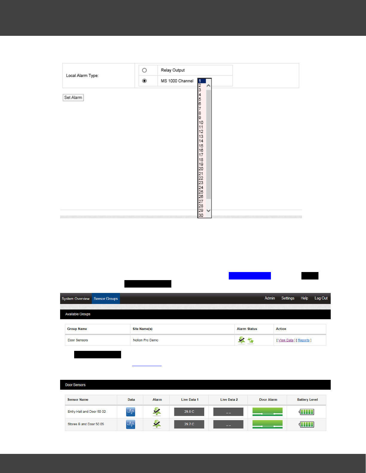
161
Notion Pro © 2017 IMC Group Ltd HP5525 Version 1.2.15
Reference Section
MS 1000 Channel text, this displays the MS1000 channel options, see below.
Select the required channel number (up to 32 channels are available). When the required
Local Alarm has been selected, click Set Alarm to save the setting.
5.4.3 Viewing Sensor Groups
To Sensor Groups that have already been created select Sensor Groups from the Home
menu bar to give the Available Groups dialogue box, see below.
The Available Groups dialogue gives you an alarm status summary for the sensors which
form the Group. Clicking View Data shows you the Live View for the sensors in that group.
See below for example.

162
Notion Pro © 2017 IMC Group Ltd HP5525 Version 1.2.15
Reference Section
See Viewing Data for details of the facilities available from the Live View window. You can
also generate Reports for the sensors in the Group by clicking on Reports. See Setting Up
and Running Reports.
Note: An unlimited Sites and Sensor Groups licence can be purchased, IMC product code
W604. Contact IMC Group Ltd for details.
5.5 Viewing Data
This topic gives detailed information on how to view live data coming from the sensors in
your Installation.
5.5.1 Signing In
First Time Login (Any User)
To view the Notion Pro website, you will need to open a browser and navigate to the Notion
Pro site.
If you are working on the Notion Pro Server itself, enter http://localhost/NotionPro in the
browser’s address field.
If you are working on a another computer or device, you will need to use the URL supplied
by your System Administrator or IT Support provider to reach the Notion Pro server. This
may be similar to ServerName/NotionPro for a LAN connection or www.mycompany.com/
NotionPro for an internet connection.
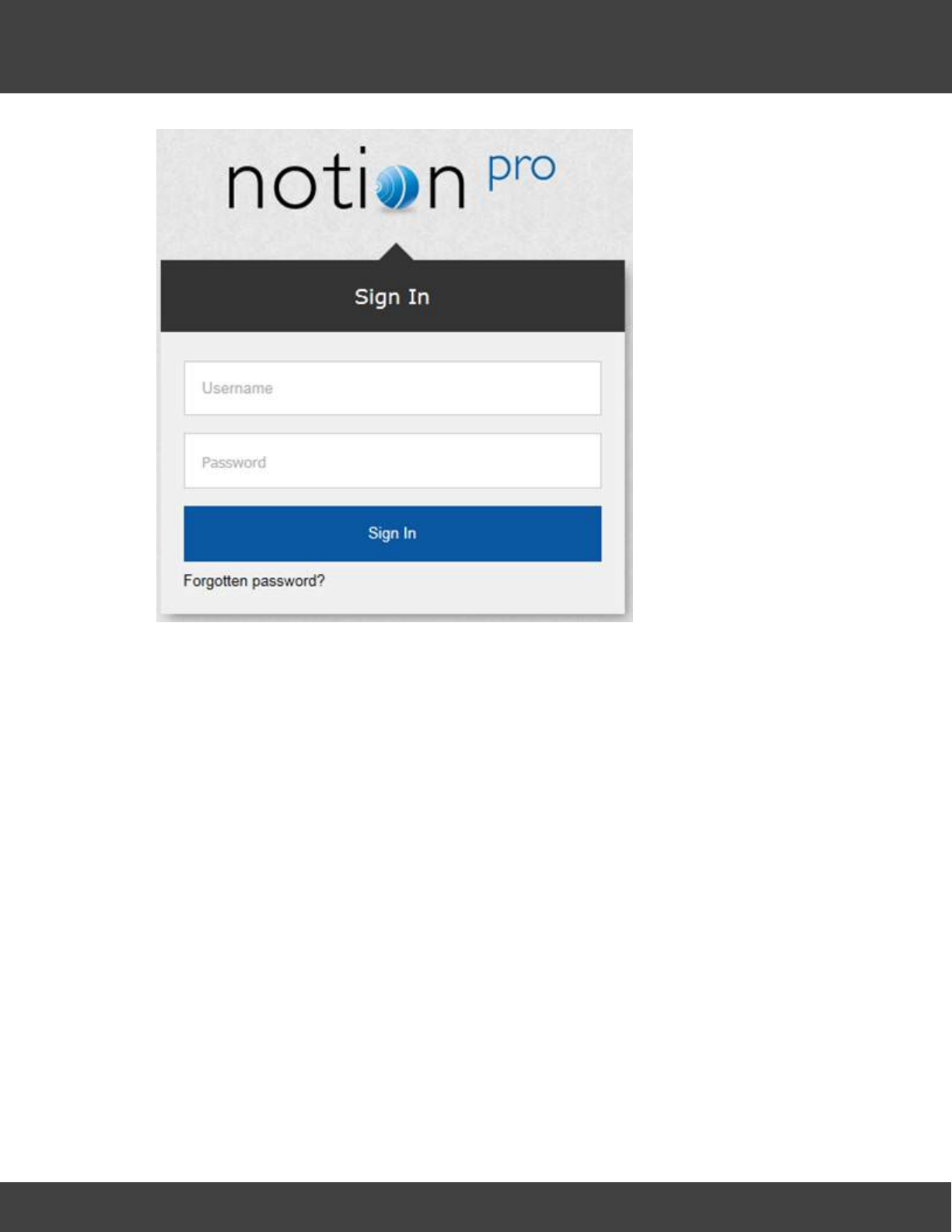
163
Notion Pro © 2017 IMC Group Ltd HP5525 Version 1.2.15
Reference Section
Once you have navigated to the correct URL, the login screen will be displayed, as above.
Log in using the username and password that the System Administrator has given you.
Enter your username and password to login, then click Sign In. Passwords are case
sensitive.
The first time you log in you must supply the answer to a security question, so if you forget
your password in the future, you can retrieve it using a procedure which includes supplying
the answer to your security question. See below.
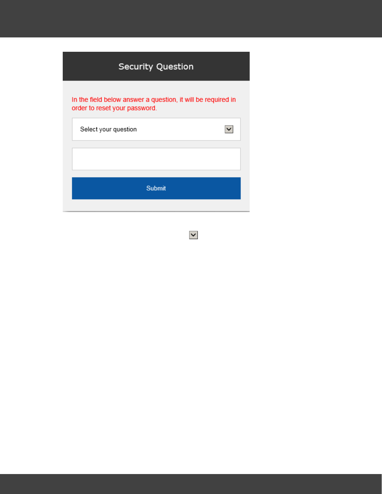
164
Notion Pro © 2017 IMC Group Ltd HP5525 Version 1.2.15
Reference Section
Choose your security question by clicking and choosing from the list. Type the answer
into the box below, and then click Submit.
You will now be returned to the login screen see above, where you will again need to enter
your username and password.
Subsequent Logins (Any User)
Once you have navigated to the correct URL, the login screen will be displayed, see 132
below.

165
Notion Pro © 2017 IMC Group Ltd HP5525 Version 1.2.15
Reference Section
Log in using the username and password that the System Administrator has given you.
If you have forgotten your password click Forgotten password? and work through the
procedure that follows. You will need to know the answer to your Security Question to be
able to do this.
Archived Databases
Archived Databases will probably only be present if the Notion Pro installation at your site has
been running for some time, and if the System Administrator has performed one or more
archive operations.
If you login as System Administrator, or with a username with the Access Archive Database
permission set, then the Choose Database screen will be displayed, see below.
If your Username does not have the Access Archive Database Permission set, then Notion
Pro will go straight to the live system Home screen.
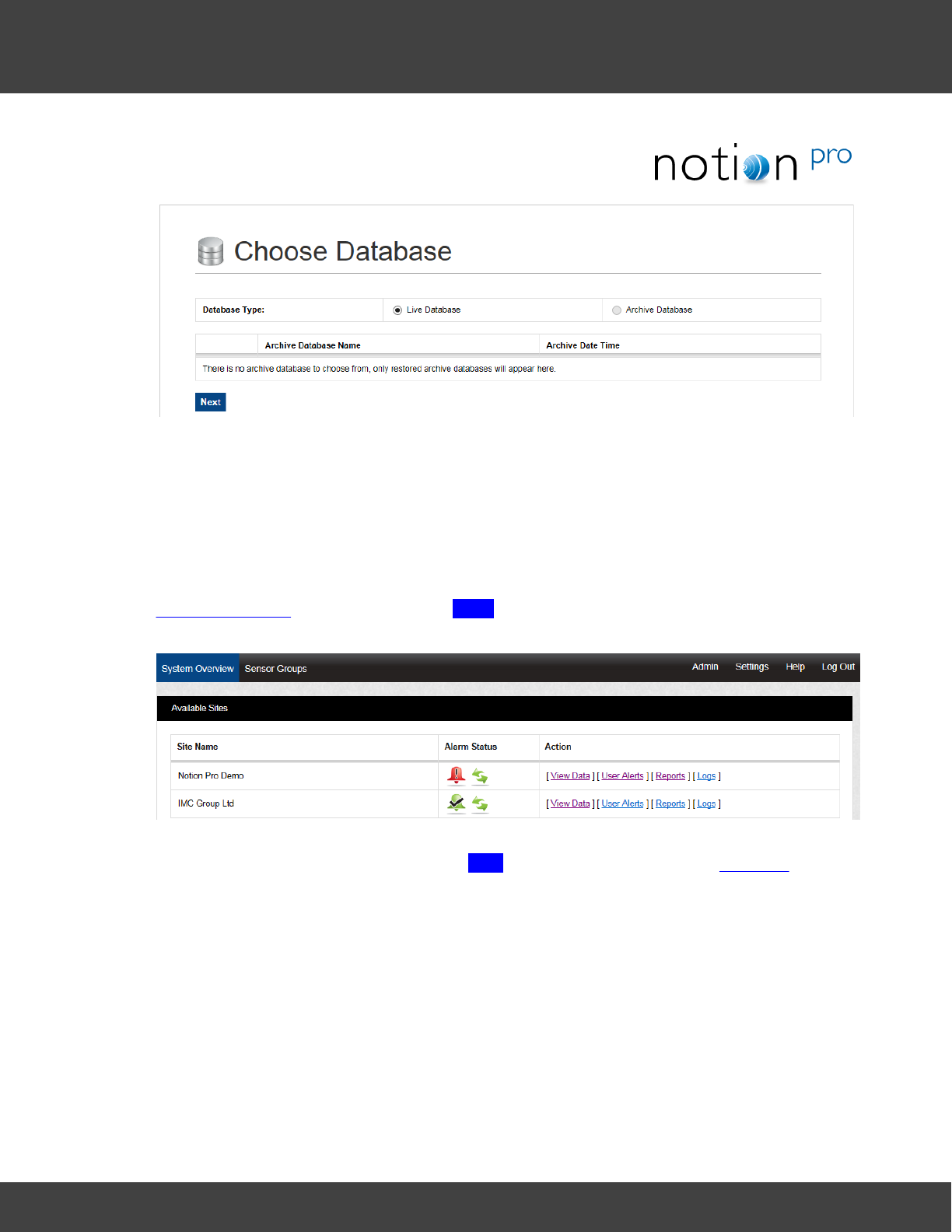
166
Notion Pro © 2017 IMC Group Ltd HP5525 Version 1.2.15
Reference Section
To access archived data, click Archive Database, select the required Archive Database, then
click Next. For detailed information about the Notion Pro Archive / Backup system, see the
IceSpy Notion Pro Archive/Backup Manual, doc no IM5549.
5.5.2 Viewing the Live Database
To access the live Notion Pro system, make sure Live Database is selected on the
Choose Database dialog box then click Next to give the System Overview, see below for
an example.
Note: You will only see the Available Sites view if your installation has more than one Site.
For a one-Site installation, clicking Next will take you straight to the Live View.
5.5.3 Choosing the Site to View
On logging in to Notion Pro, you are presented with the System Overview display, see
below.
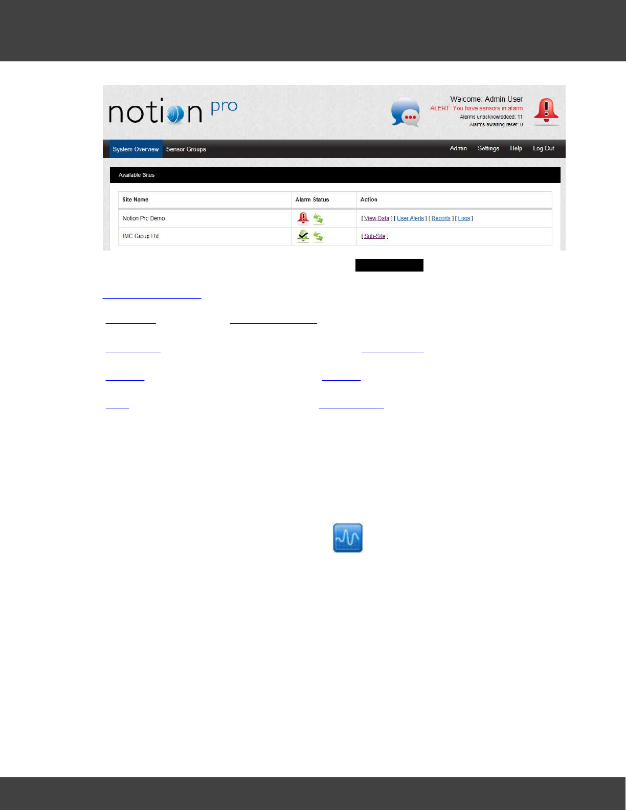
167
Notion Pro © 2017 IMC Group Ltd HP5525 Version 1.2.15
Reference Section
The icons under the Alarm Status column in the Available Sites window show the alarm
and sensor communication status of the Site under the Site Name column on the left. See
Alarm Management for details of Alarms. The available Actions for each Site are:
View Data
(see also Viewing Live Data)
User Alerts
Allows you to set up email and SMS Alert Groups.
Reports
Allows you to create sensor Reports.
Logs
Allows you to view and edit System Logs.
5.5.4 Operations from the Live View
The Graphical Display
To view the graph data for a Sensor click the icon for the sensor on the Live View,
or double-click on the Sensor Name to give the same graph in its own window. See below for
an example graph.
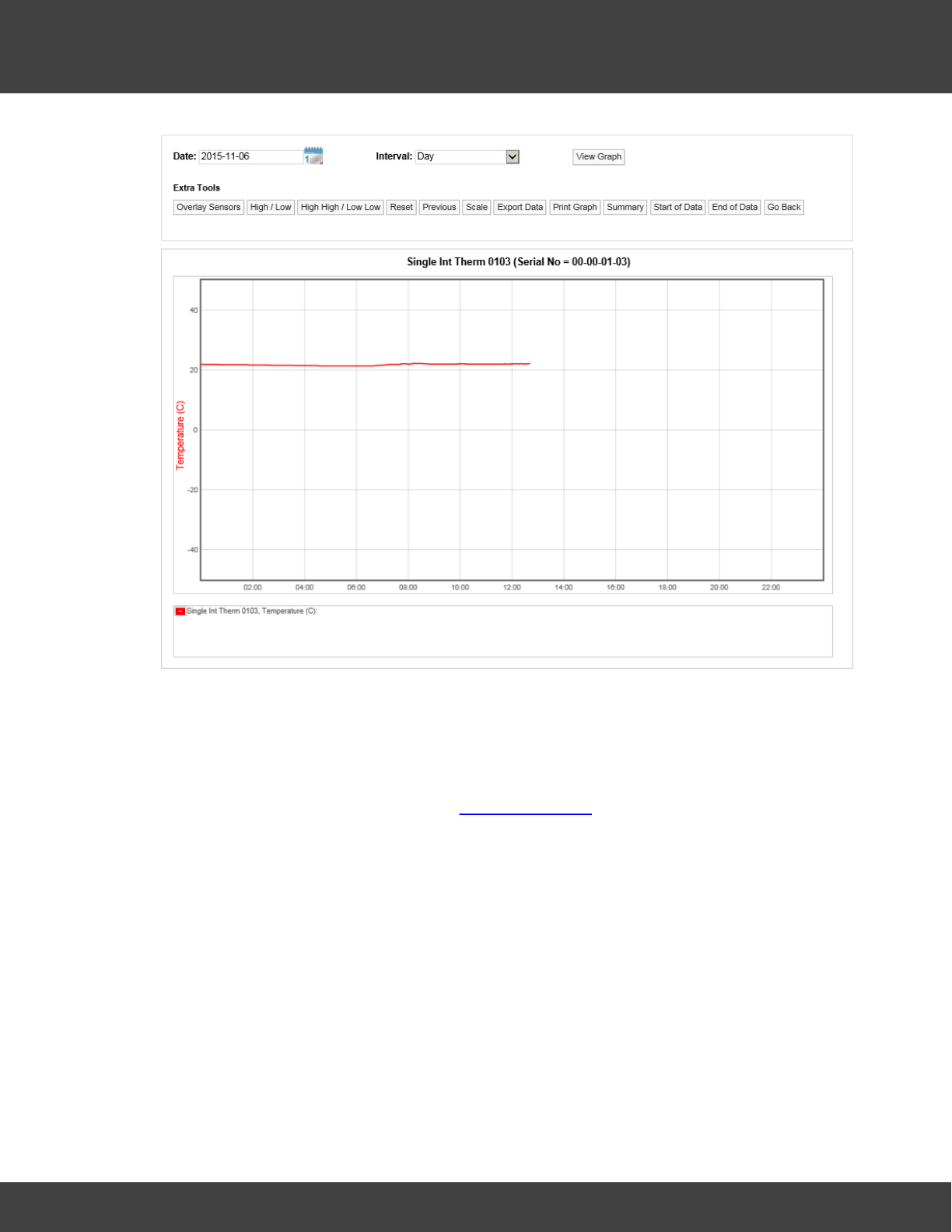
168
Notion Pro © 2017 IMC Group Ltd HP5525 Version 1.2.15
Reference Section
Line Graph, Temperature Data
Here, the graph shows live temperature data, starting at midnight for the 'Single Int Therm
0103' sensor. Summary data in textual form is shown in the display box under the graph
area.
Double-click on the Sensor Name in the Viewing Live Data list to give the same graph in its
own window.
An example of a graph for a two-channel sensor might be as shown below:
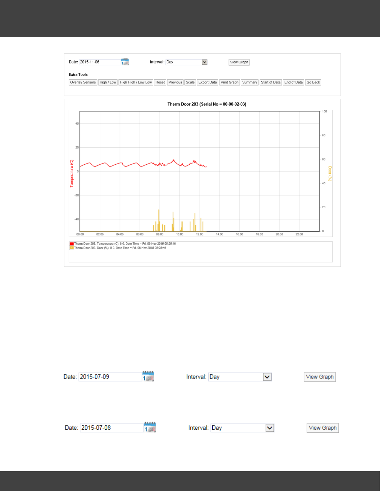
169
Notion Pro © 2017 IMC Group Ltd HP5525 Version 1.2.15
Reference Section
Line Graph, Temperature Data and Door State Data
Here we see temperature data in red, door data in yellow. The door sensor graph line
indicates the percentage of time in each data period that the door was open. This could be
one continuous period or an accumulation of several periods.
Display Time Spans
The graph window defaults to displaying the current day’s data.
To change the date range for the graphing period, use the Date and Interval controls,
see below.
Select the calendar icon to change the data graphing start date, this is the data that the
graph will start from, see below.
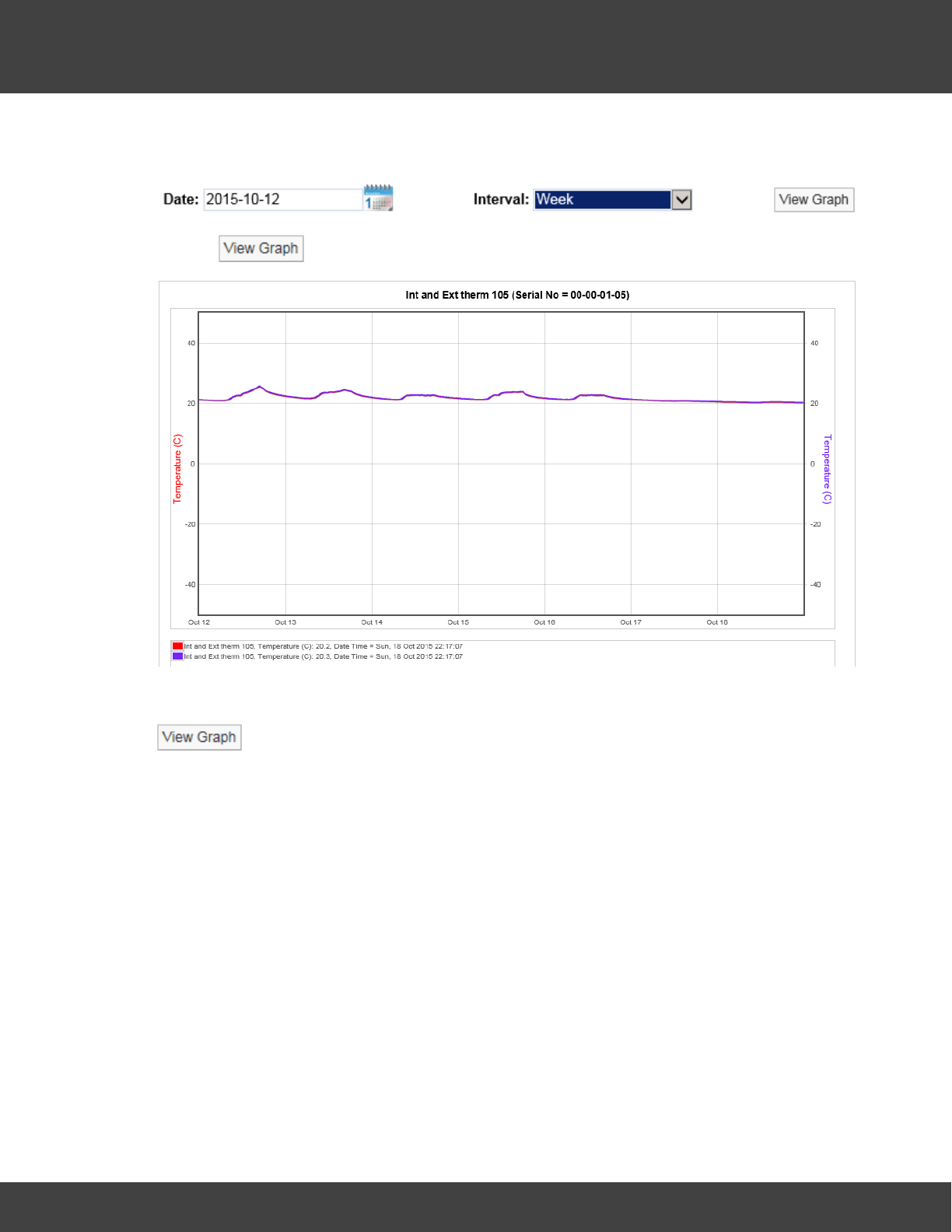
170
Notion Pro © 2017 IMC Group Ltd HP5525 Version 1.2.15
Reference Section
The date has been changed to the 8th July 2015. To view data for one week (commencing
12th of October 2015) use the Interval drop down menu and select Week, see below.
Click on to generate the graph, see below for example.
To view data for a month follow the steps above, selecting a date from the calendar that is
a month or more prior to the current date, set the Interval to Month and select
, see below.
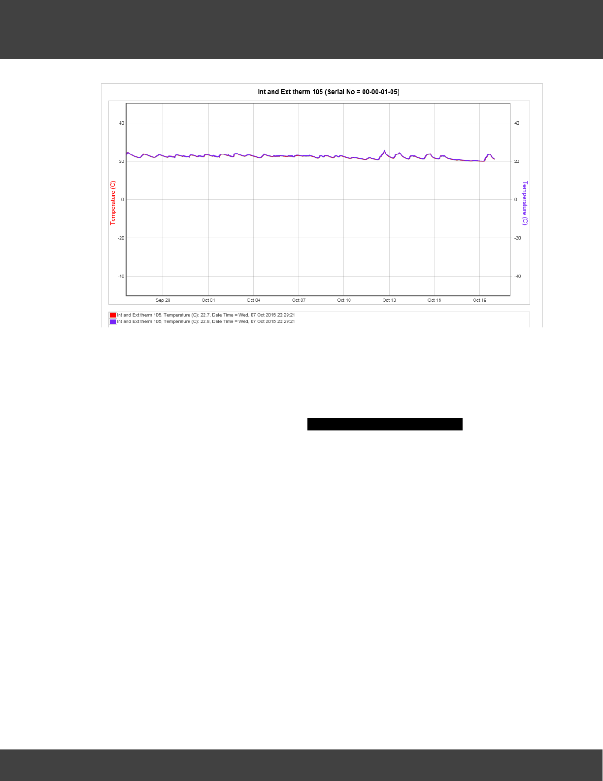
171
Notion Pro © 2017 IMC Group Ltd HP5525 Version 1.2.15
Reference Section
Using the tools above the graph window the following functions can be performed.
Overlay Sensors
This feature allows the comparison of one or more sensors. This is particularly useful if you
have an outdoor sensor and want to see if the outdoor conditions are driving the conditions
indoors. To overlay sensors, in Live View select Overlay Sensors from the bar menu in
the Live View window. A new window called Select Sensors to Overlay Graph will appear, see
below.
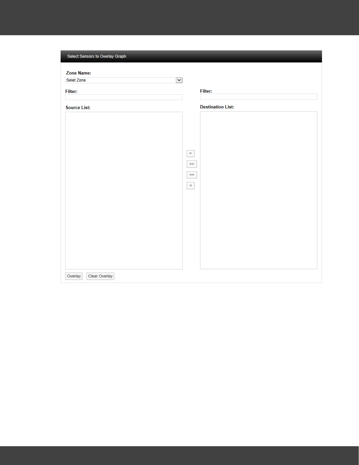
172
Notion Pro © 2017 IMC Group Ltd HP5525 Version 1.2.15
Reference Section
Select the Zone containing the relevant sensors from the Zone Name: pull-down list. See
below.
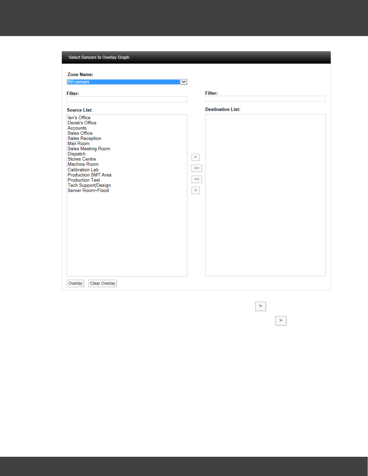
173
Notion Pro © 2017 IMC Group Ltd HP5525 Version 1.2.15
Reference Section
Select the sensor(s) you require from the Source List then click . To select more than
one sensor, hold down the Ctrl key as you select the sensors, then click . See below.
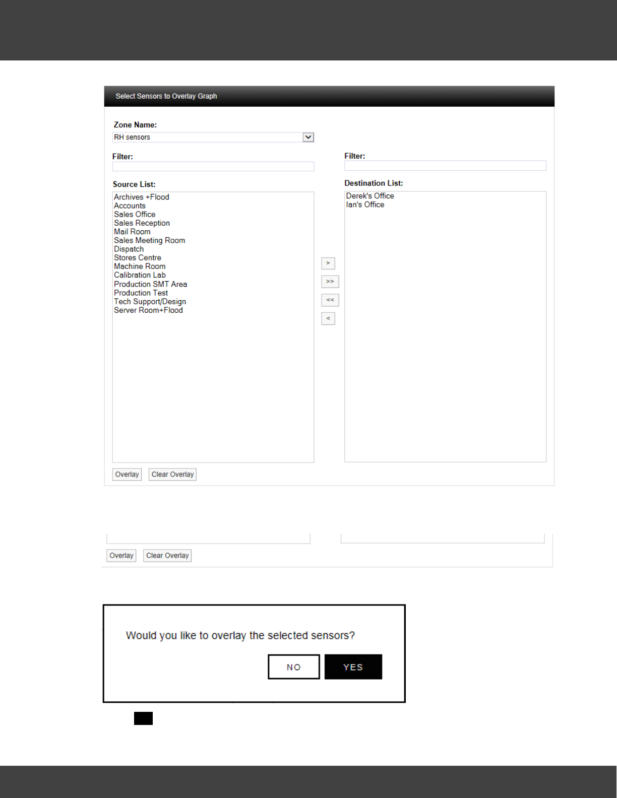
174
Notion Pro © 2017 IMC Group Ltd HP5525 Version 1.2.15
Reference Section
Once you are happy with your selection, scroll to the bottom of the list and select Overlay,
see below.
After selecting Overlay you will be asked to confirm your selection, see below.
Select YES to confirm and to proceed with overlaying data. The graph window will re-appear
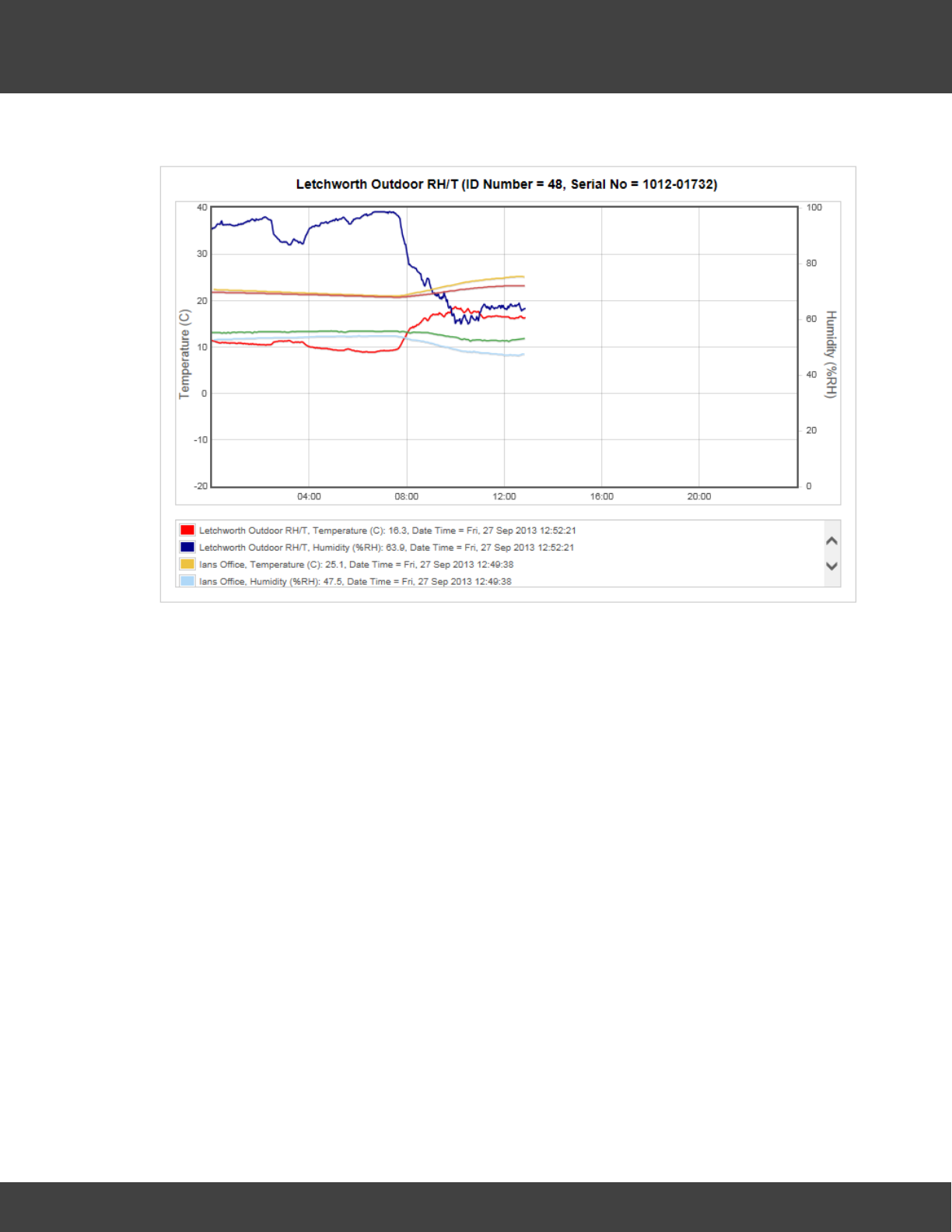
175
Notion Pro © 2017 IMC Group Ltd HP5525 Version 1.2.15
Reference Section
with the selected Sensors overlaid over the original graph, see below.
The coloured key below the graph window clearly identifies the overlaid data traces. To see
all the key information use the scroll bars to view the lower data. To view specific values on
the graph a cursor can be applied, to use the cursor move the mouse pointer over the
graph window and the cursor will appear, see below.
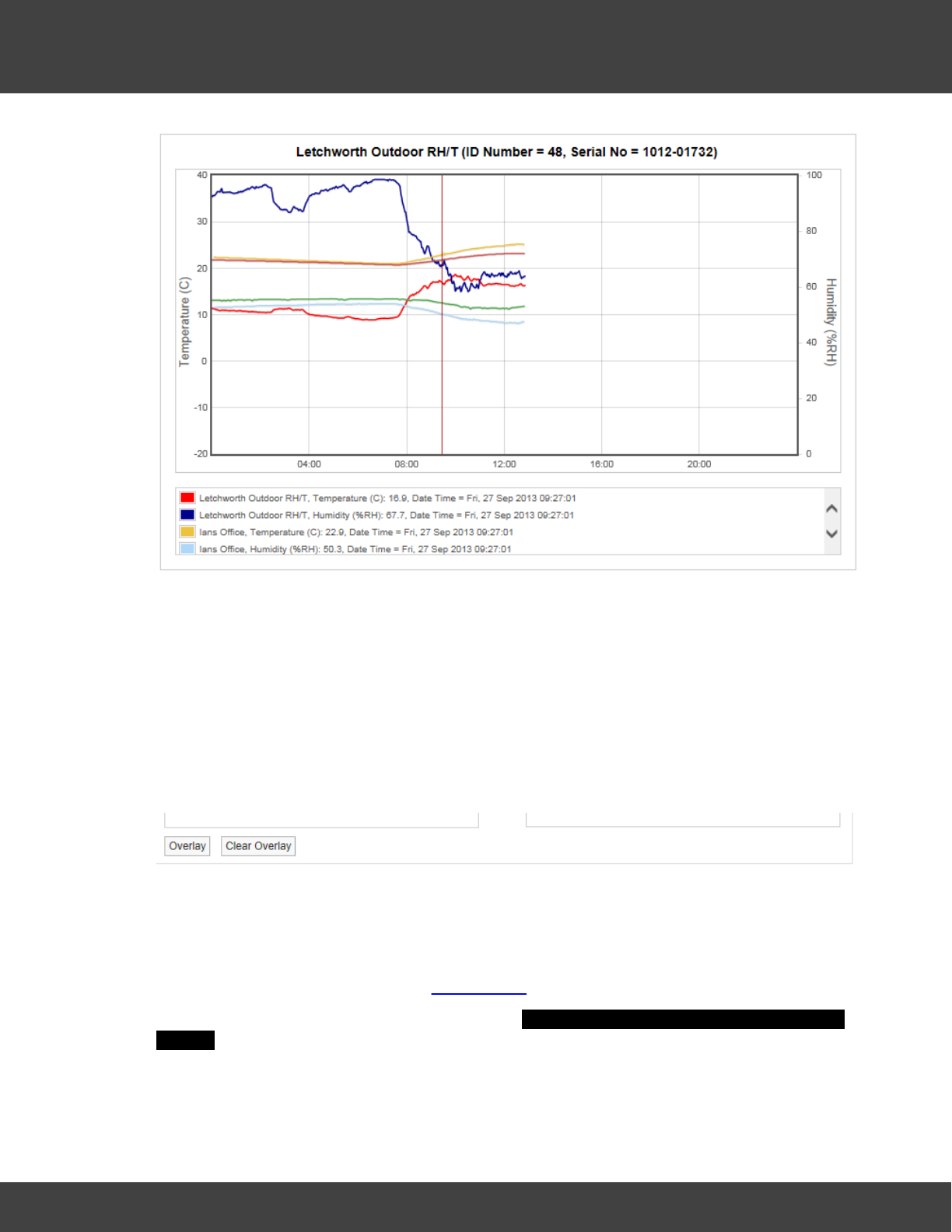
176
Notion Pro © 2017 IMC Group Ltd HP5525 Version 1.2.15
Reference Section
Keeping the mouse pointer within the graph window, move the mouse to the left and right
to move the cursor across the screen. As the cursor moves you will see the sensor values,
along with the date and time, changing.
You can see from the above that as the outside temperature (red trace) increases the two
indoor temperature traces (salmon and mustard) are moving up as well. This indicates that
the equipment controlling the indoor space is not powerful enough to overcome the effects
of the outside temperature changes.
To remove the overlay select the Overlay Sensors button and scroll to the bottom of the
Sensor list and select Clear Overlay, see below.
The graph data will return to the original data.
High Low Alarm
This feature allows the levels for alarms to be overlaid on the graph. To use this feature
alarm levels will need to be set, see Add Sensors for how to set alarms.
Click on the High Low Alarm button, then the Select Channel to Display High / Low Alarm
Settings window appears, see below.
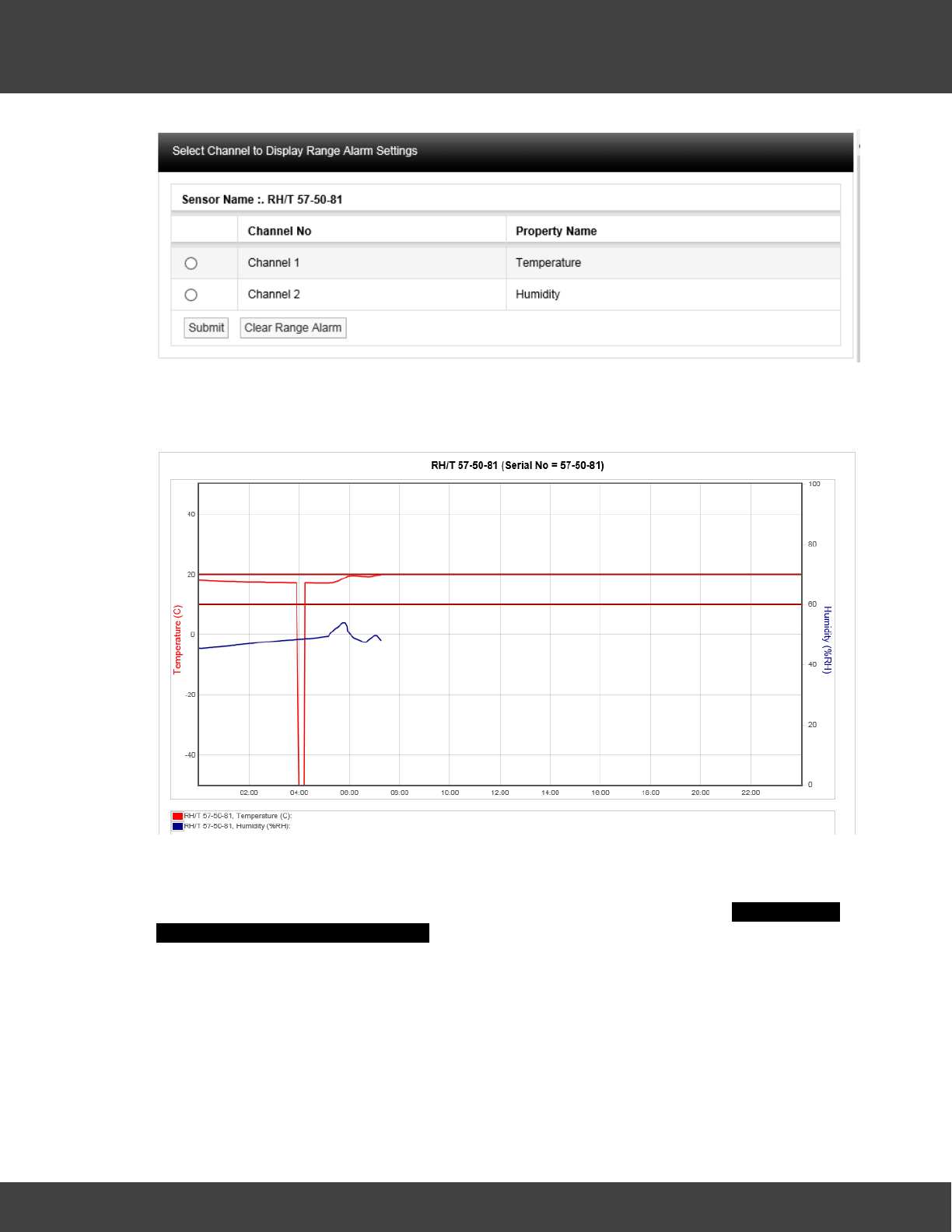
177
Notion Pro © 2017 IMC Group Ltd HP5525 Version 1.2.15
Reference Section
To bring on the temperature range alarms select the option button next to Channel 1 and
select Submit. Lines representing where the range alarm levels are set will appear on the
graph, see below.
This gives a clear visual indication if there has been an excursion either above or below the
range alarm settings.
To clear the Alarm select High / Low Alarm from the graph window, the Select Channel
to Display High / Low Alarm Settings window will appear again, this time the Channel that has
been put on the graph will be highlighted. See below.
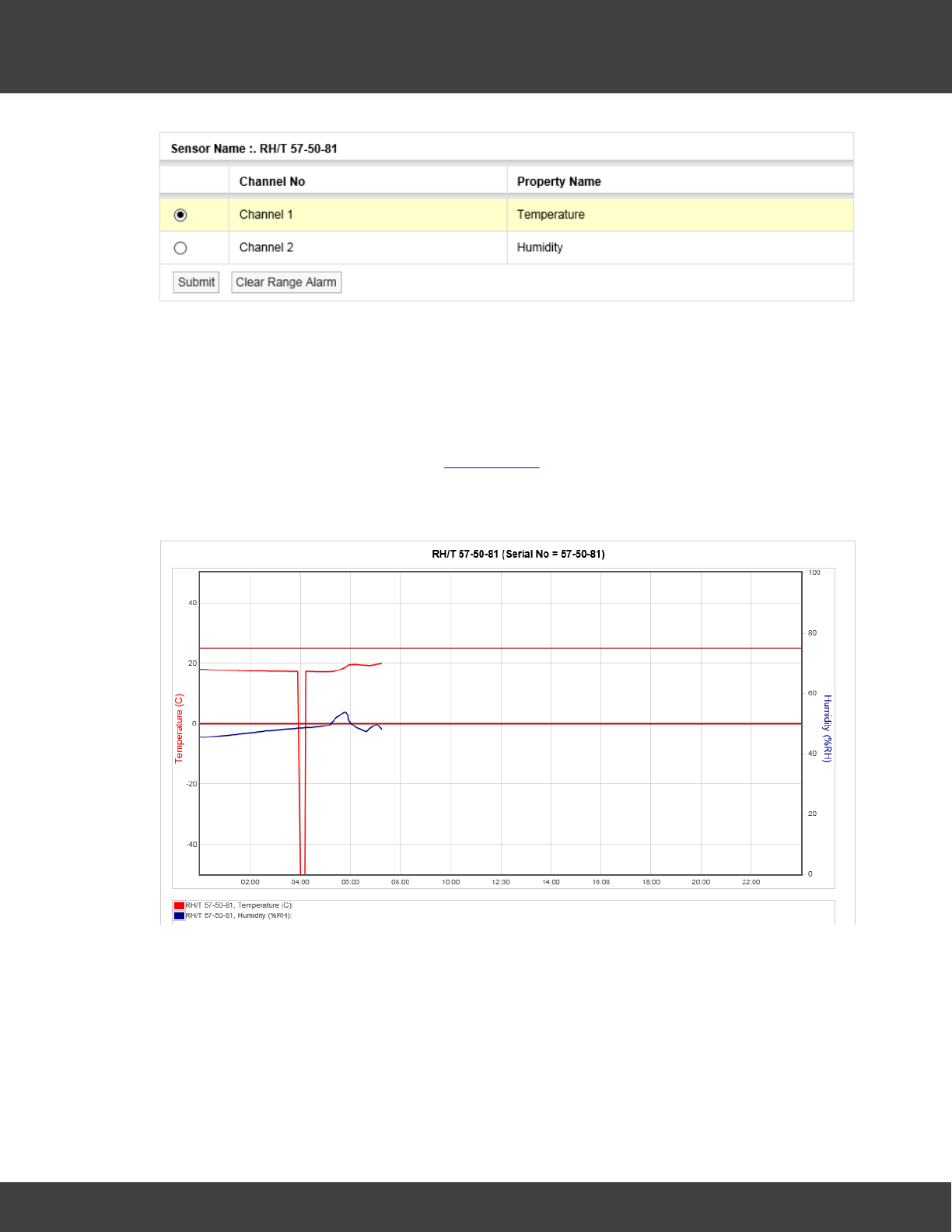
178
Notion Pro © 2017 IMC Group Ltd HP5525 Version 1.2.15
Reference Section
Select Clear Range Alarm to remove the Range Alarms from the graph.
High High / Low Low Alarm
This feature has the same function as the High / Low Alarms only this time the High
High and Low Low alarm levels are overlaid on the graph. Level Alarms are set in a similar
way to Range Alarms. To start the routine, select High High / Low Low Alarm from the
toolbar above the graph window. See Add Sensors section for setting alarm levels (System
Administrator Users Only).
The result here might be as shown below.
(Temperature has gone below the Low Low setting in the above example).
Reset
This function will clear the graph window back to the default view regardless of where you
are. The default view is the current date with one day’s data displayed. To reset the graph
select Reset from the menu above the graph window.
Previous
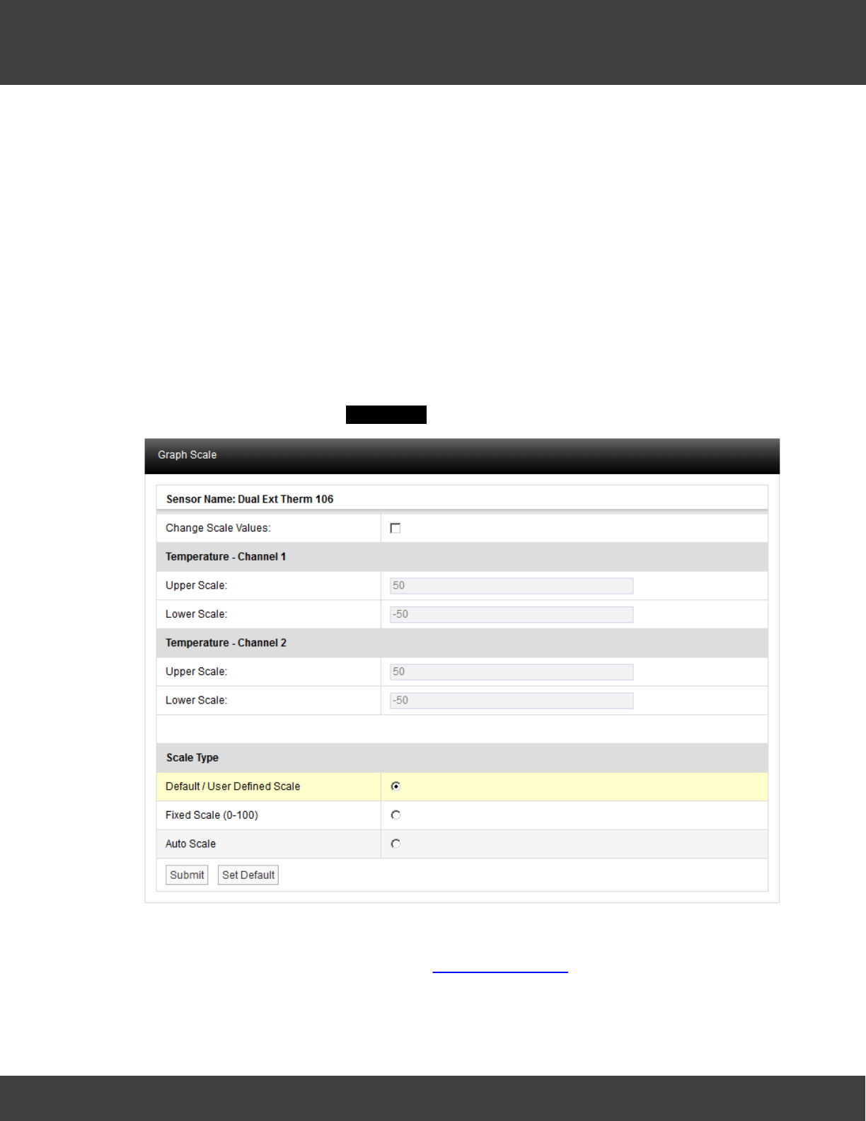
179
Notion Pro © 2017 IMC Group Ltd HP5525 Version 1.2.15
Reference Section
The Previous function steps you back through the data one graph span at a time. If the
Interval is set to Day then the graph will step in days, Week and it will step in weeks, Month
it will step in months.
Next
The Next function steps you forward through the data one graph span at a time. If the
Interval is set to Day then the
graph will step in days, Week and it will step in weeks and Month it will step in months. When
a graph is first generated the Next button won’t be visible as there is no future data to
display. Once you select a time to graph in the past the Next button will appear.
Scale
The configuration of the graph Scale is selectable. There are three methods of selecting the
graph Scale. To change the Scale select Scale from the menu above the main graph
window. A new window called Graph Scale will appear, see below.
Default/User Defined Scale
You can define a default Scale for each Sensor on the system. The User Defined Scale can
be set here or in the Calibration page see Configuring Sensors. Some Sensors have a very
wide operating range but the Sensor in question may be being used at one end of the
range. A User Defined Scale allows a more detailed view of the data.
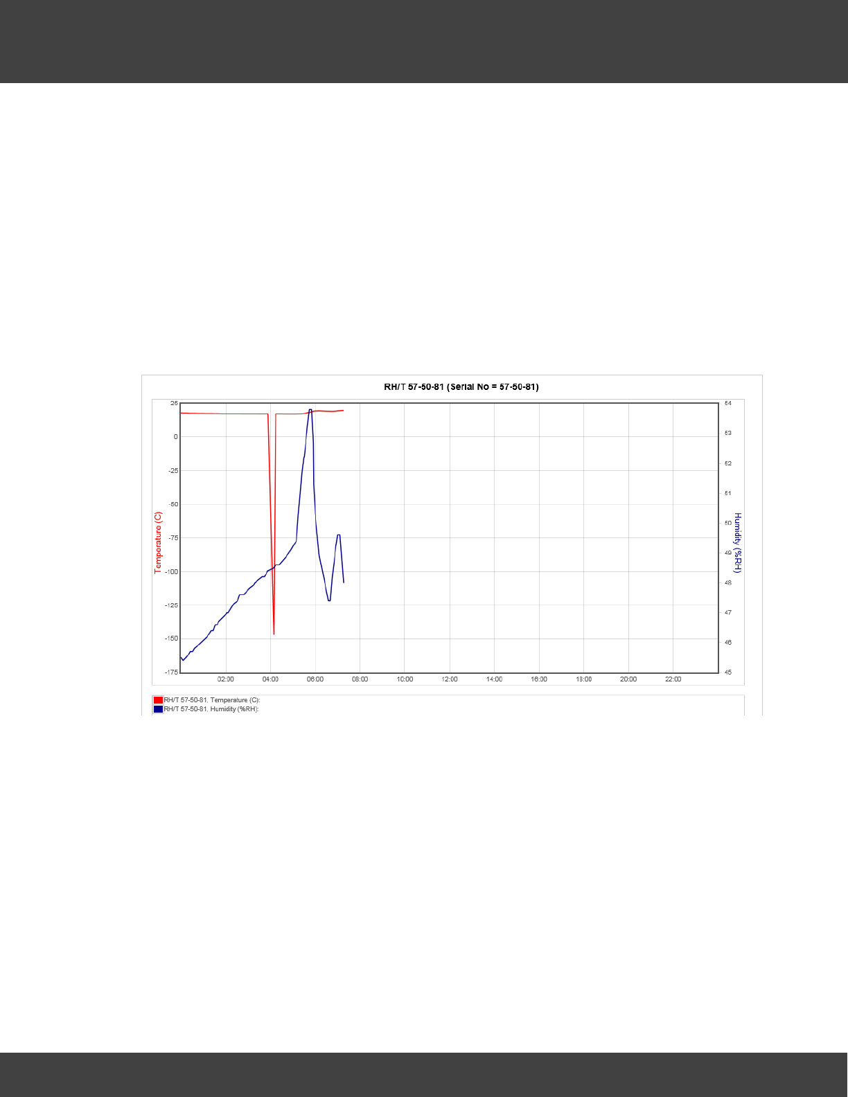
180
Notion Pro © 2017 IMC Group Ltd HP5525 Version 1.2.15
Reference Section
Fixed Scale (0-100)
Each Sensor installs with a Default Scale which would cover the maximum range for that
Sensor. This is Scale setting is OK if the Sensor is going to be used over its range. If it’s to
be used over a smaller range then a User Defined Scale may be more appropriate, see
above.
Auto Scale
This feature allows the graph Scale to be set automatically. Auto Scale will set the graph
Scale to a very tight range which covers the range for the data displayed. This gives a
much expanded view of the data and may be confusing as the data can look like it is
changing dramatically.
Select the Scale type you require by clicking the option button next to the Scale Type and
select Submit. The graph will re-draw with the new Scale settings, see below.
The User Defined Scale for this Sensor is -40°C to +40°C and 0% to 100% Relative
Humidity. Using Auto Scale has rescaled the graph to 150°C to 23°C and -165%
[theoretical] to 20% Relative Humidity.
Export Data
The data associated with Day and Week interval graphs can be saved as a comma
separated variables file, (.CSV). The entire Day or Week’s data will be exported, irrespective
of the current zoom state when the data is exported. To export data click Export Data.
Once clicked you may be asked to choose between saving the file and opening with your
computer’s default spreadsheet application (see below). However, the exact action will
depend on the browser you are using, the default settings for your browser and the
computer operating system and its setup. If you require assistance with this contact your
system administrator or IT support provider, please do NOT contact IMC Technical
Support, as this is help that only your administrator/support provider can supply.
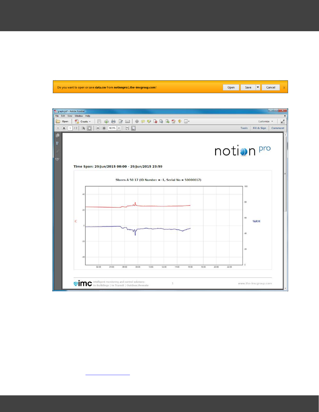
181
Notion Pro © 2017 IMC Group Ltd HP5525 Version 1.2.15
Reference Section
Print Graph
The Print Graph function allows you to export a picture of the graph (line or bar chart) in
.pdf format. Clicking on the Print Graph button gives the browser’s standard “Do you want
to open or save . . .” window. (Example below is for Internet Explorer.)
Clicking Open displays the graph in a .pdf window, with IMC headers and footers:
Select File>Save As… to save the file to your desired location with name graph.pdf,
renaming the file if required.
Start of Data, End of Data
Select Start of Data to change the graph display to the date/time when data was first
recorded by the sensor. End of Data returns the display to the show data at the current
date/time.
Go Back
Click this button to go back to the Live View display for the Zone at the top of the Live View
list. See also Viewing Live Data.
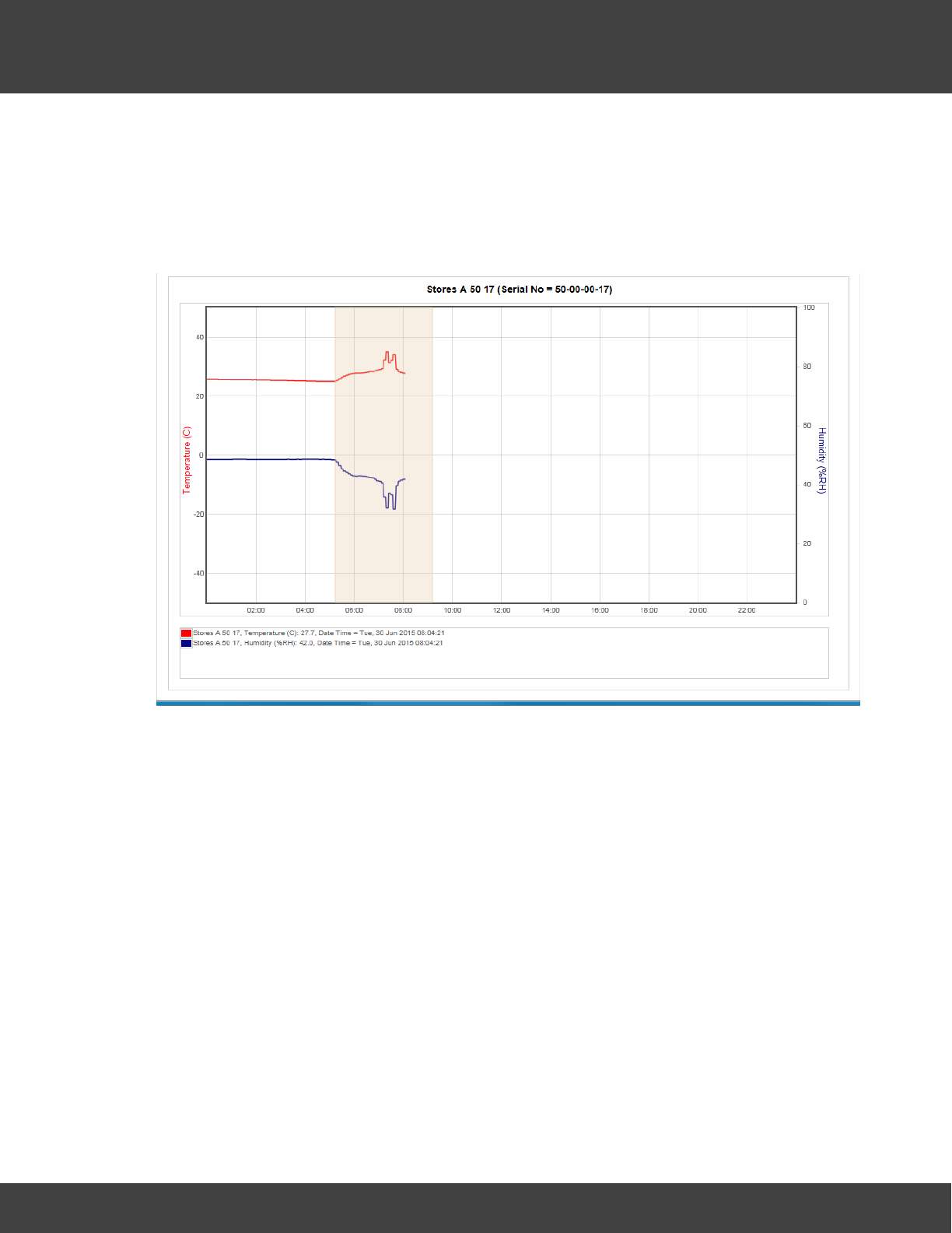
182
Notion Pro © 2017 IMC Group Ltd HP5525 Version 1.2.15
Reference Section
Zooming In
The graph can be zoomed by using the mouse. To Zoom in on a section of the graph place
the mouse cursor at the place where you want to Zoom in on, click and hold the left mouse
button and move the mouse to cover the section of the graph to Zoom in on.
When the area required is highlighted release the left mouse button, see below.
The graph will re-draw, zoomed into the area selected, see below.
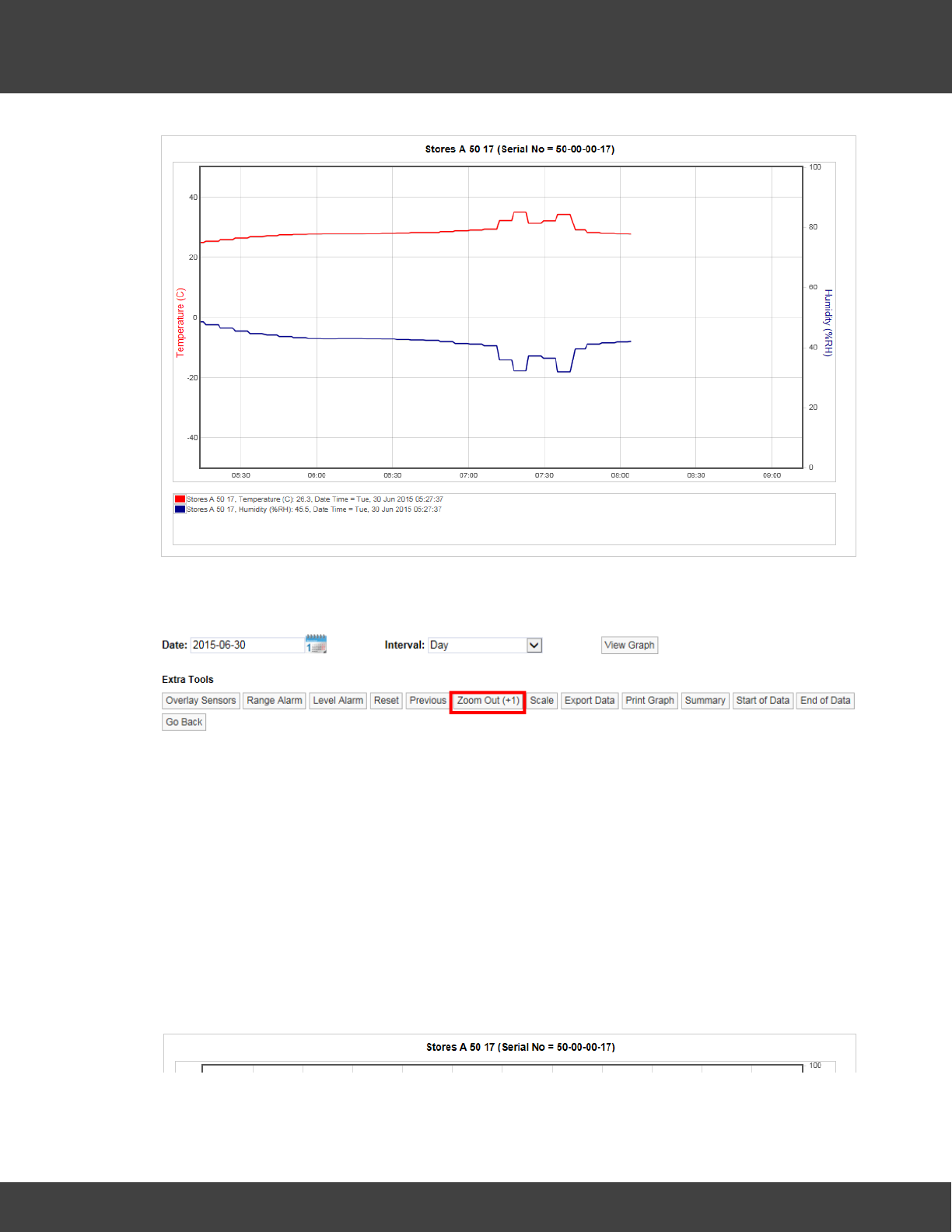
183
Notion Pro © 2017 IMC Group Ltd HP5525 Version 1.2.15
Reference Section
Once the graph has been zoomed a new button (Zoom Out) will appear on the graph
toolbar, see below.
The new button will Zoom the graph out. You will see that Zoom Out is followed by a
number in brackets. In the example above (+1) tells you that the graph has been zoomed
one time. If the number in brackets was (+3) that would indicate that the graph has been
zoomed three times.
Clicking the Zoom Out button once will take you back one step. To go back to no Zoom in
one step you can select Reset. Once the graph has been returned to an un-zoomed view
the Zoom Out button will disappear.
Graph Title
The graph title appears above the graph and is auto generated by the system. The name
consists of the Station name allocated by the user when the Sensor was added to the
system and the serial number, see below.
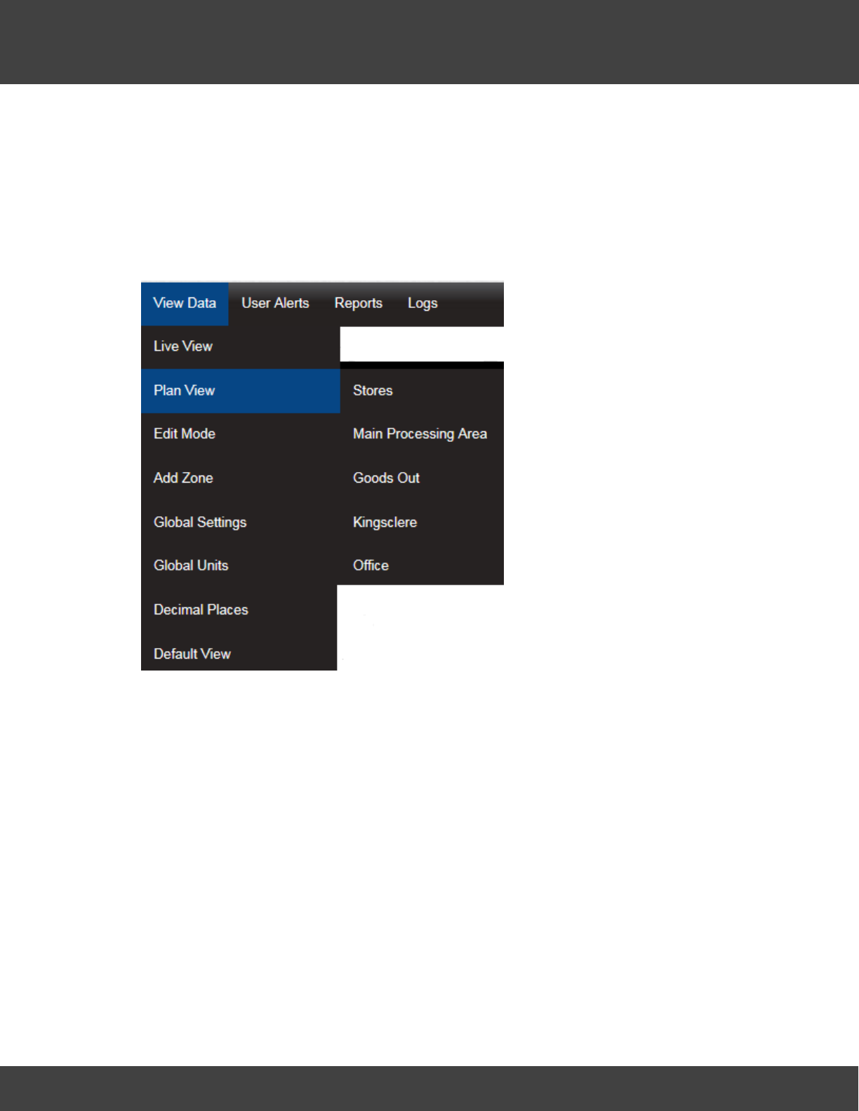
184
Notion Pro © 2017 IMC Group Ltd HP5525 Version 1.2.15
Reference Section
5.5.5 The Plan View
Notion Pro allows you to allocate Plans to a Zone. Plan View gives a graphical view of the
data. To access Plan View select View Data>Plan View from the top menu bar, see
below.
To add a Plan select Browse... to locate a suitable Plan file if available, suitable Plan
formats are .gif, jpg and .png and should be no larger than 30K, see below.
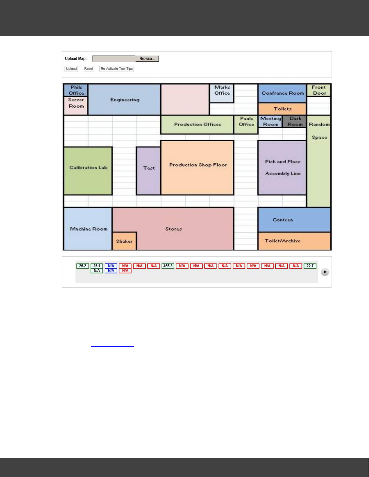
185
Notion Pro © 2017 IMC Group Ltd HP5525 Version 1.2.15
Reference Section
Once a suitable Plan has been located select Upload to load the image.
When a plan is first loaded all the sensor icons will be located along the bottom bar. The
icons can be dragged to the Plan by moving the mouse pointer over the icon, holding down
the left mouse button and dragging the required sensor icon to the desired location on the
Plan, see below. You must have the Plan View Edit Permission set to Allow to be able to do
this. (See Access Control).
‘Out of Service’ sensors are displayed on the Plan View in blue, see below.
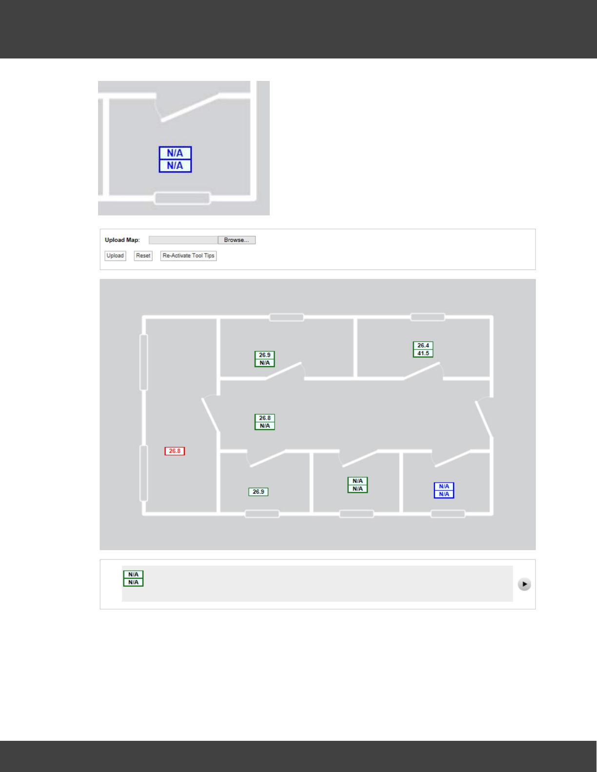
186
Notion Pro © 2017 IMC Group Ltd HP5525 Version 1.2.15
Reference Section
Each channel is represented by a single block. A double-channel device is represented by
two blocks, a three-channel device by three blocks. See below for an example.
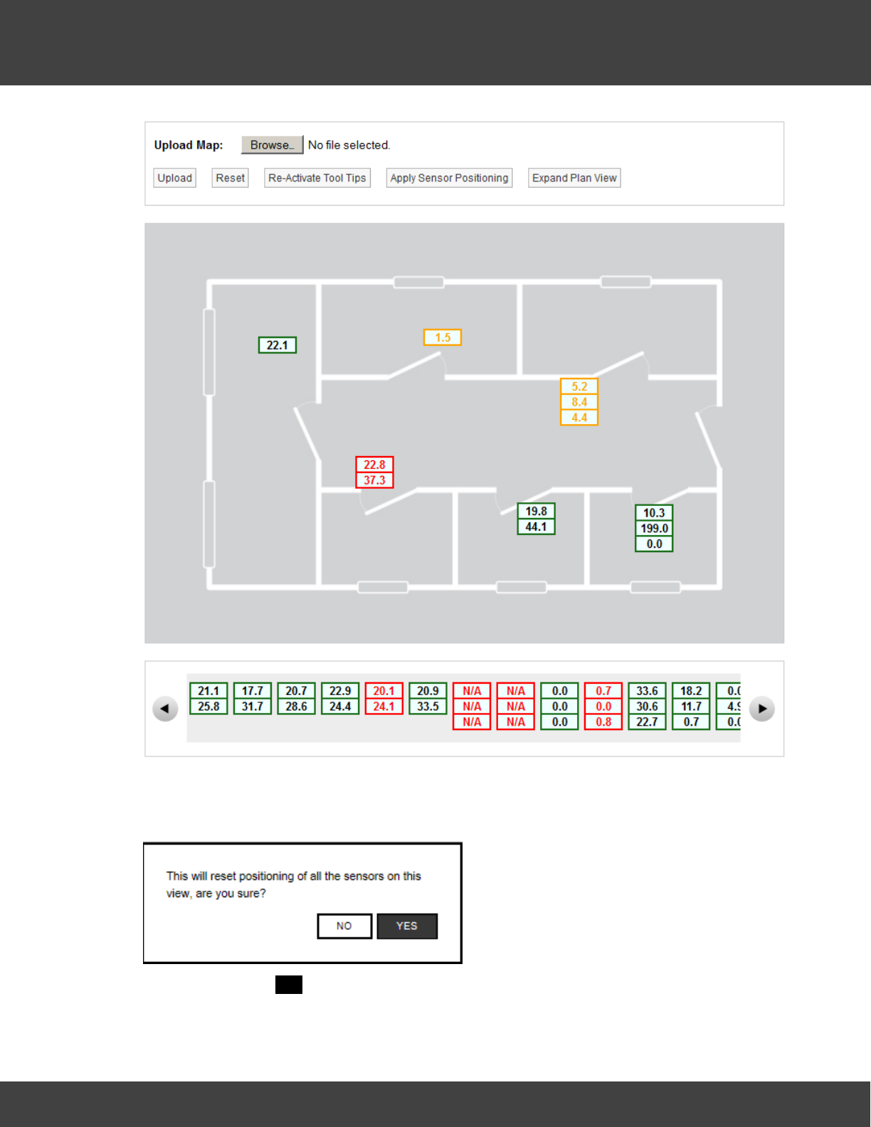
187
Notion Pro © 2017 IMC Group Ltd HP5525 Version 1.2.15
Reference Section
If required all icons can be removed from the Plan to the bottom bar, to perform this
function select Reset, you will get a confirmation request, see below.
To continue select YES, all icons will be moved to the bottom bar.
Moving the mouse pointer over a Sensor icon displays a tool tip with the sensor name and
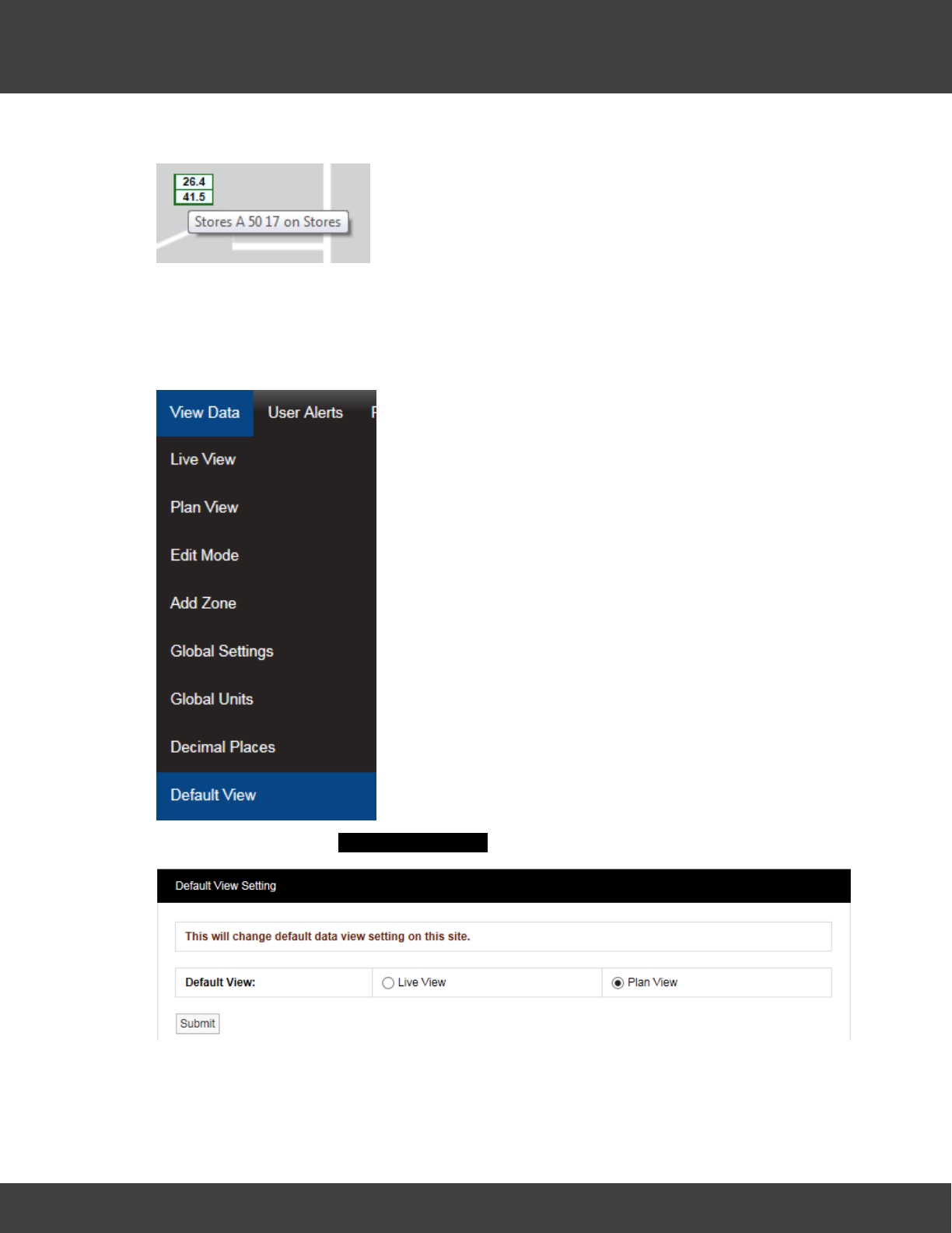
188
Notion Pro © 2017 IMC Group Ltd HP5525 Version 1.2.15
Reference Section
its parent Zone. See below. Click Re-Activate Tool Tips if the tool tips are not visible.
5.5.6 The Default View
The Live View is the default view type following Notion Pro install, but you can change this
to the Plan View if required. To do this, begin by selecting View Data>Default View,
see below.
This selection gives the Default View Setting dialogue box, see below.
Select the required default view type, then click Submit.
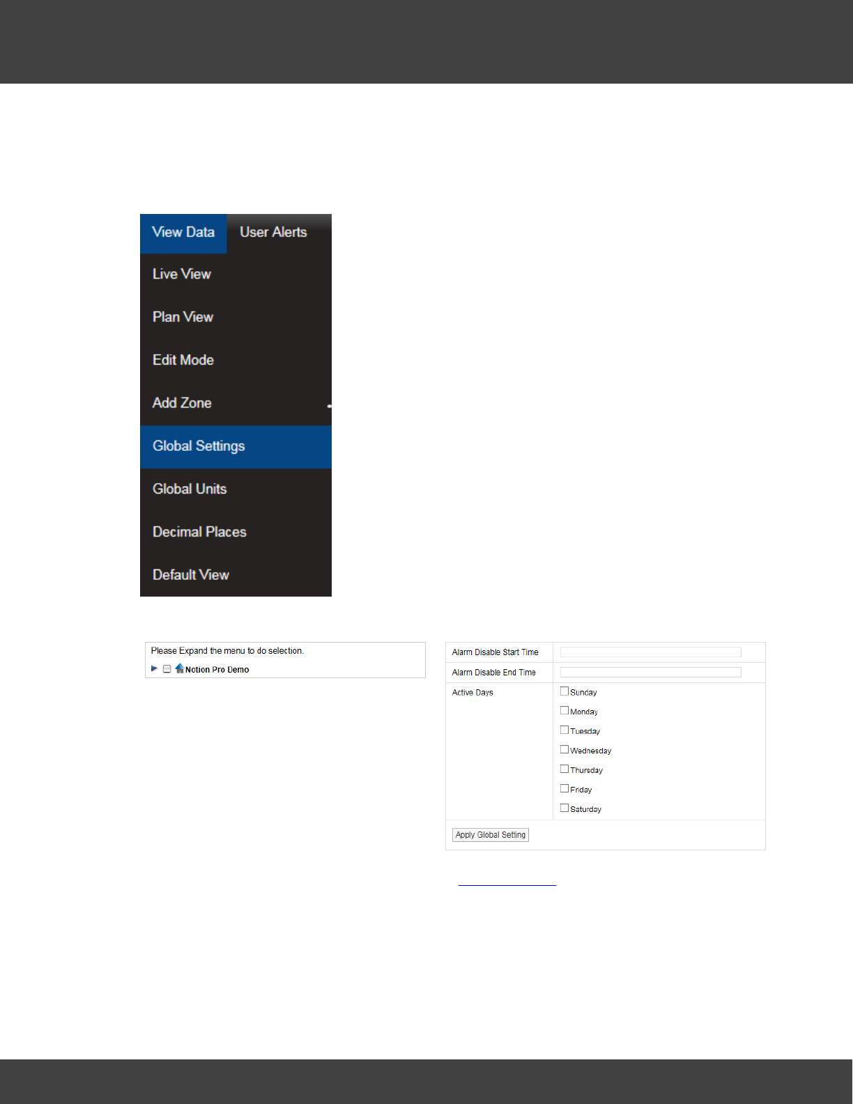
189
Notion Pro © 2017 IMC Group Ltd HP5525 Version 1.2.15
Reference Section
5.5.7 Global Settings
Global Settings allows alarm disable times and days to be set across a range of Sensors. To
access Global Settings select View Data>Global Settings from the top menu bar, see
below.
After selecting Global Settings a new page will appear, see below.
For information on setting times and days see Setting Alarms, once the times and days
have been set use the Site and Zone tree on the left side to select which Sites and Zones to
apply the changes to. (Click on the desired Site, the Zone tree then expands underneath it,
see below for an example.)

190
Notion Pro © 2017 IMC Group Ltd HP5525 Version 1.2.15
Reference Section
For example, setting Active Days to Sunday to Saturday (by selecting the 'day' tick boxes,
see above, then using the tree view shown immediately above to select those Zones (or
individual sensors within the Zones) to which the global settings are to apply, then selecting
Apply Global Setting will result in all selected sensors becoming active Sunday-Saturday
inclusive.
5.5.8 Global Units
Global Units allow common Sensor value types to be displayed using alternative units, for
example displaying Temperature values as Fahrenheit instead of Celsius. To access the
Global Units window, select View Data>Global Units, see below.
After selecting Global Units the Edit/View Global Units window will display, see below.
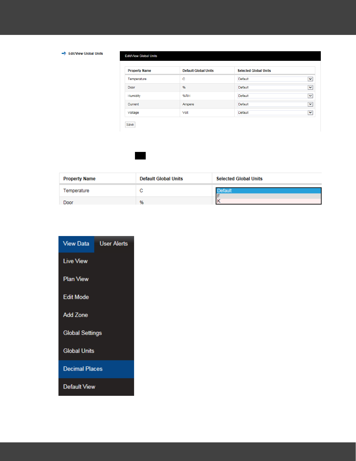
191
Notion Pro © 2017 IMC Group Ltd HP5525 Version 1.2.15
Reference Section
To change the units used for Temperature, for example, click the down arrow to the right
of Default and select the required unit option, F or K, see below, then click Save. When
asked ‘Are you sure?’ click YES to confirm.
5.5.9 Decimal Places
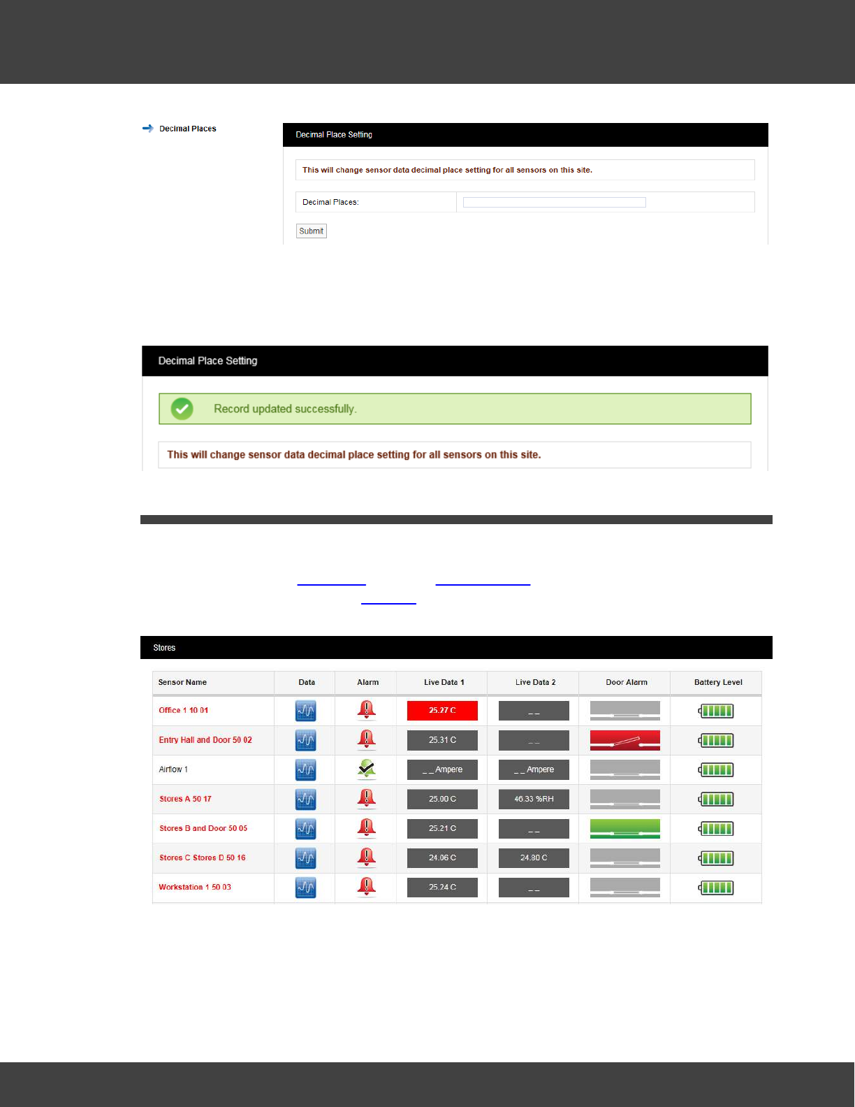
192
Notion Pro © 2017 IMC Group Ltd HP5525 Version 1.2.15
Reference Section
This window allows you to set the number of decimal places to be used to display sensor
data. Enter the number of decimal places you require in the Decimal Places: field and click
Submit. A confirmation window will appear confirming that the setting has been applied, see
below.
5.6 Viewing Live Data
Viewing Live Data
To view live data, click View Data from the Available Sites dialogue box. For a Site which has
Sub-Sites you must first click on Sub-Site and select the sub-site of interest to give the Live
View window. See example below.
Zone Selection
The example Live Data display above is for sensors in the Stores Zone – see top left
corner. To choose another Zone, select View Data>Live View and then move the
mouse pointer to the right to show the Zones within the current Site. See below.
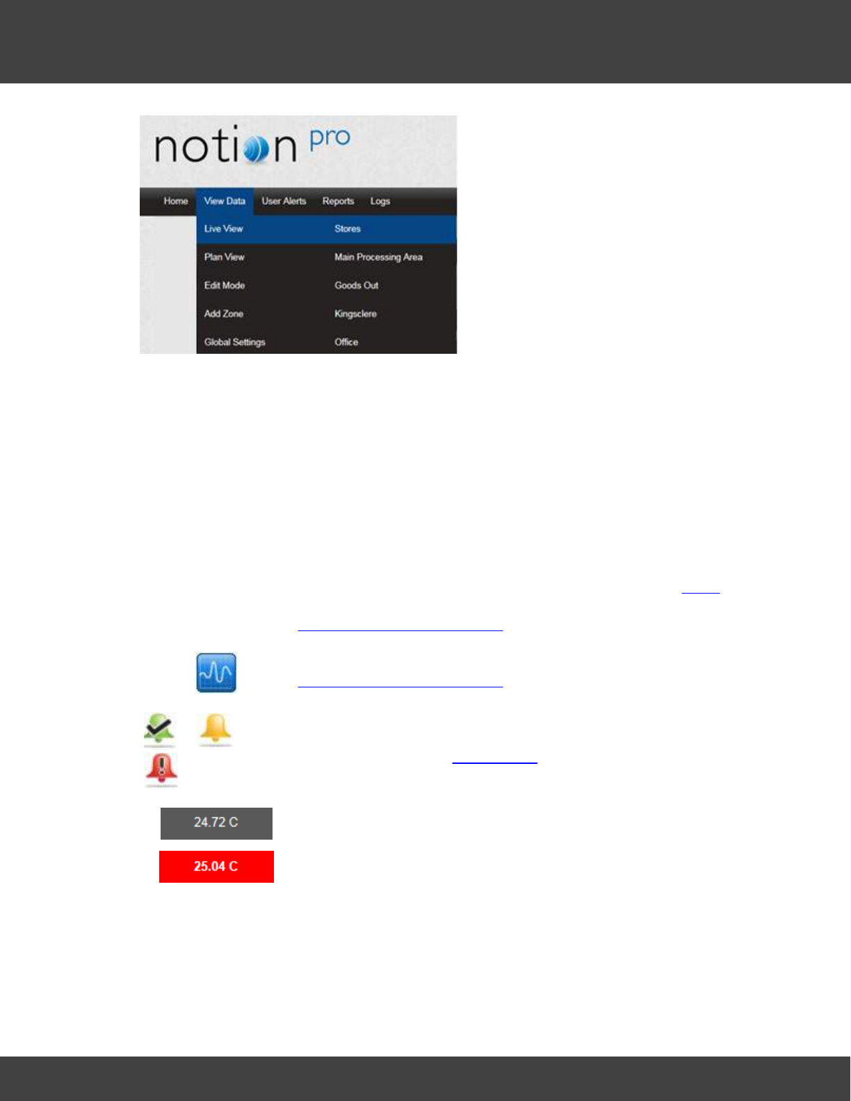
193
Notion Pro © 2017 IMC Group Ltd HP5525 Version 1.2.15
Reference Section
Live View Controls and Indicators
Sensor Name
The colour of the text for each named sensor in this column gives
an indication of its state:
Black
– sensor giving normal reading, within alarm threshold.
Red
– sensor in alarm condition.
Orange
– sensor in alarm condition, but alarm has been acknowledged.
Blue
– sensor is out of service.
Single-clicking on this text gives more information – see below.
Double-clicking opens graphical display of the live sensor data – see
Operations from the Live View
Click on this to give a graphical display of the sensor data – see
Operations from the Live View.
This icon indicates the alarm status of the sensor.
The current reading for the sensor channel. Typically, channel 1
would be for temperature data, channel 2 for relative humidity.
A red icon indicates that the sensor reading has gone over its alarm
threshold value.
The Door Alarm icons indicate the state of the door alarm channel (if present):
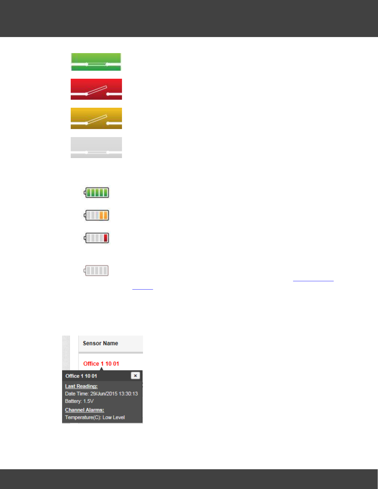
194
Notion Pro © 2017 IMC Group Ltd HP5525 Version 1.2.15
Reference Section
The door is closed.
The door is open and the alarm has not been acknowledged.
The door is open and the alarm has been acknowledged.
There is no door monitoring and alarm function associated with this
transmitter.
The battery icons indicate the state of the battery for the associated transmitter:
Battery is fully charged.
Battery has less than half its life left, but need not be replaced yet.
Battery is very low and should be replaced as soon as possible.
Battery is empty and must be replaced immediately. Note: Scout/
Legacy sensors do not output battery information and so the
battery display symbol will always be grey. Check for Elapsed Time
Alarms.
Alarm Condition Tooltips
Click once on the sensor name to show the current alarm status for that sensor. See below
for example.
Here we see the date and time of the previous reading from the sensor, also the current
battery voltage. The channel 1 temperature value is below the Low Level value that has
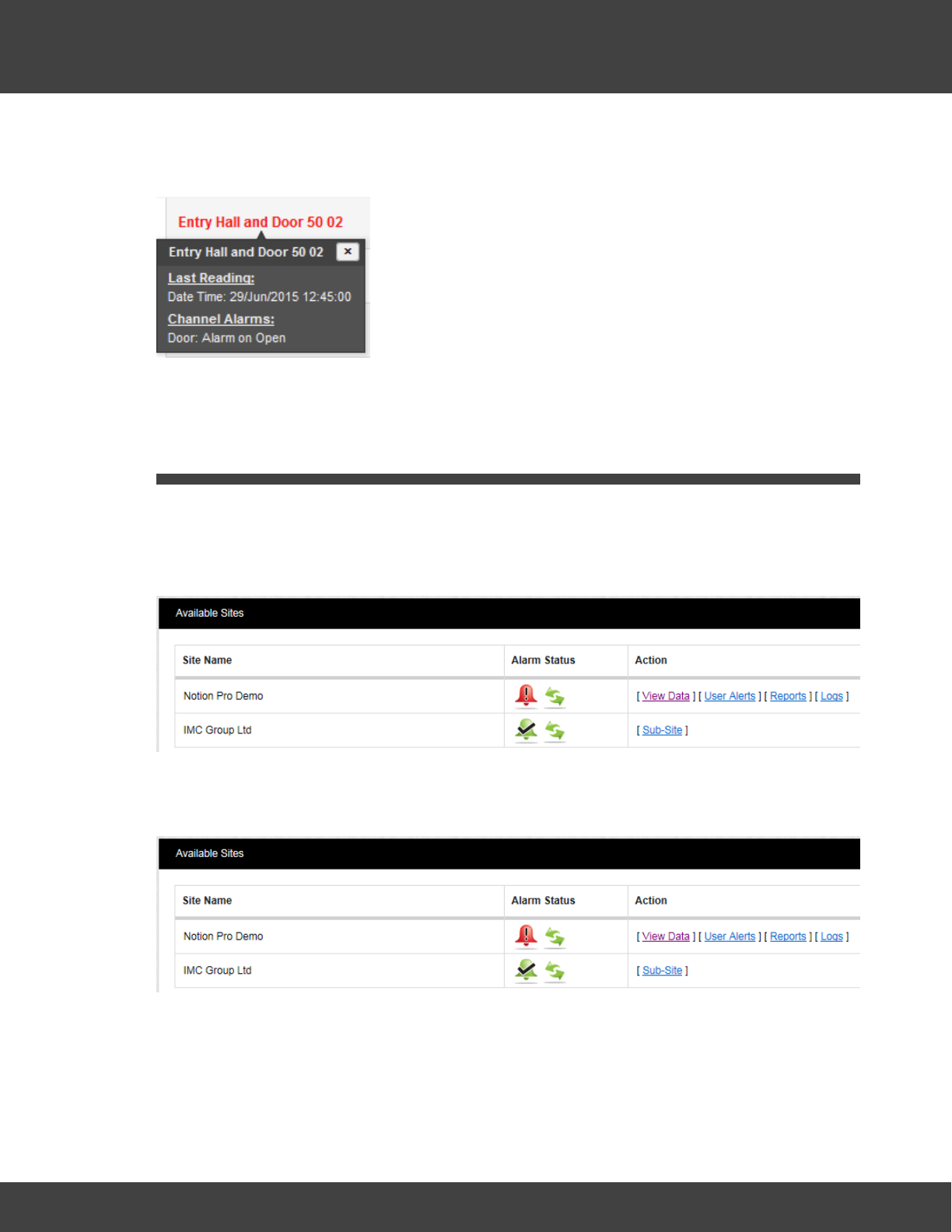
195
Notion Pro © 2017 IMC Group Ltd HP5525 Version 1.2.15
Reference Section
been set, and so is giving an alarm.
An ‘open door’ alarm might be as shown below.
5.7 Alarm Management
This section will take you through managing alarms generated by the system. When the
User first signs in to Notion Pro the first screen gives an overview of the system. The
overall system alarm status can be seen by looking at the Alarm icons under Alarm Status,
see below:
5.7.1 System Status Overview
We can see straight away that there are alarms on the Notion Pro Demo Site, but no
alarms on the IMC Group Site.
System Messages
System Messages can be viewed from the System Message Alert icon, see the example
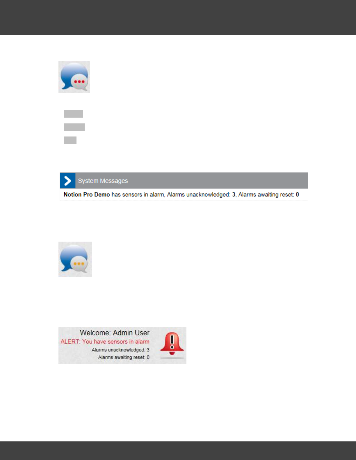
196
Notion Pro © 2017 IMC Group Ltd HP5525 Version 1.2.15
Reference Section
below:
The three coloured dots indicate the system message status:
·White there are no system messages
·Amber there no new unread system messages
·Red there are new unread system messages
To view the System Messages click on the System Status message bubble. A new
window will appear, see below for example:
The System Messages inform you of where on the system the Alarms are. Once this
window is closed the System Message bubble changes to amber which indicates that there
are still live messages but there are no new ones since the last time the System Messages
were checked, see example below.
The Status Message bubble is amber.
System Alarm Status Overview
The Alarm icon on the top right of the main screen gives a system wide view of the Alarm
status, see the example below.
The following data is shown:
·The User that is logged in, in this example it is Admin User
·The number of unacknowledged alarms, in this example there are three
·The number alarms awaiting reset, in this example there are none.

197
Notion Pro © 2017 IMC Group Ltd HP5525 Version 1.2.15
Reference Section
The individual Site icons show the alarm status for that individual Site only, see Available
Sites above. The icon indicates that Control Device communications are operating
normally, (see below for details).
Communications Status
The green connection icon, shown under Alarm Status on the Available Sites
dialog box, indicates that communications to all control devices (such as Network
Receivers) associated with the site are operating normally.
If communications have been lost to one or more of the sites control devices,
the connection icon will display in red and entries will be added to the activity log.
Locating Alarms on the System
There are two ways that you can find Alarms on the system:
Method 1
Select Home (or System Overview) from the main menu bar.
This takes you to the main System Overview (Available Sites) screen. If any Sites that are
visible are in Alarm their individual Alarm icons will have turned red.
Method 2
Click on the main Alarm icon, see below.
Wherever you are in Notion Pro, clicking this icon will take you back to the System
Overview screen, so you can tell which Site(s) contain the sensors that are in alarm.
5.7.2 Acknowledging Alarms
Acknowledge Individual Alarms
To acknowledge an individual Alarm click on the red Alarm Bell in the line in the Live View
corresponding to the sensor that you want to acknowledge the alarm for. The
Acknowledging Alarm for window appears, see below.
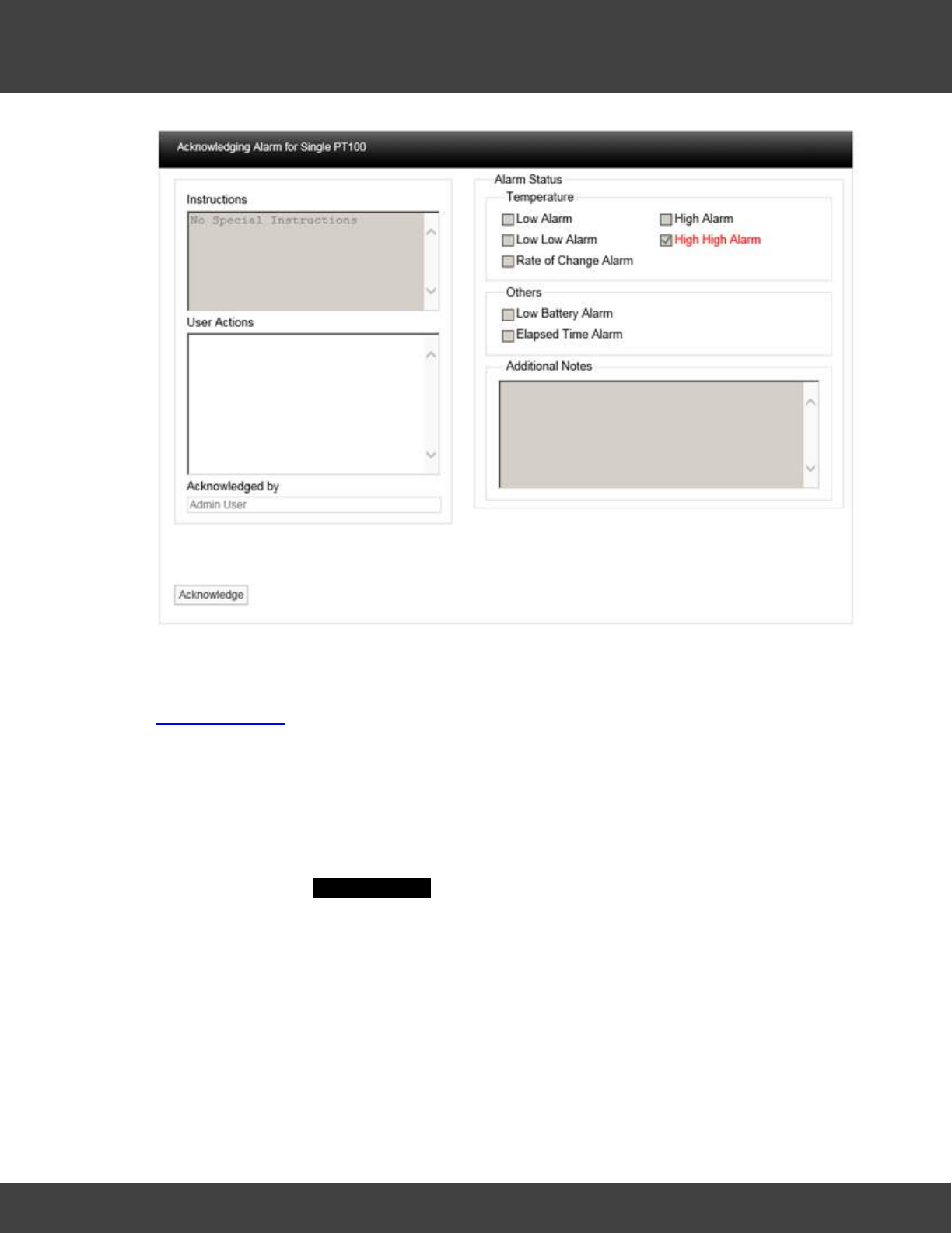
198
Notion Pro © 2017 IMC Group Ltd HP5525 Version 1.2.15
Reference Section
The type of Alarm will be highlighted in Red, in this example it is a High High Alarm for
Temperature. If there were special instruction added when the alarm parameters were set
these would appear in the Instructions text box. For more information on instructions see
Setting Alarms (System Administrator Users Only).
In the User Actions text box enter a note that is relevant to the Alarm, for example
“Humidifier out of water, humidifier tank filled up”. You cannot acknowledge the Alarm
without putting something in this dialog box. When happy click Acknowledge. The window
will close and the Alarm icon will turn amber which indicates an acknowledged state.
When you are satisfied that either the cause of the alarm has been resolved and the
conditions returned to normal limits the Alarm can be completed. To reset the alarm click on
the amber icon, the Reset Alarm for window will appear, see below.
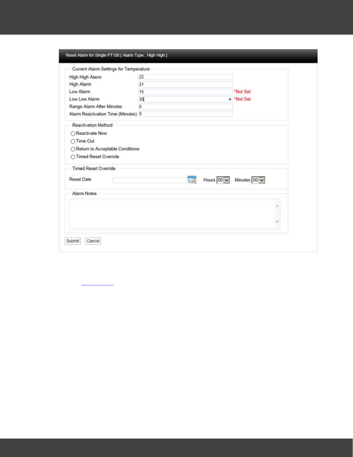
199
Notion Pro © 2017 IMC Group Ltd HP5525 Version 1.2.15
Reference Section
This window allows several features to be used.
The Current Alarm Settings are displayed at the top of the window, if the logged in User
has the Permissions these limits can be adjusted at this stage. Caution Note: Any changes
made here will be written back to the main database.
There are four methods available to reset the Alarm:
Reactivate Now
If Reactivate Now is selected as soon as you select Submit the Alarm will be
acknowledged. If the Alarm condition still exists the status will return to red and a new Alarm
will be generated on the system. If the Alarm conditions have returned to normal the amber
Alarm icon will be removed from the list.
When selecting Reactivate Now a default message “Reactivate Now was selected for
this Alarm” will be entered into the Alarm Notes text box. This can be added to or
overwritten.
Time Out
If Time Out is selected as soon as you select Submit, the Alarm will be acknowledged
after the time delay entered into the Alarm Reactivation Time (Minutes) dialog box. If the
Alarm condition still exists after the Time Out period the status will return to Red and a new
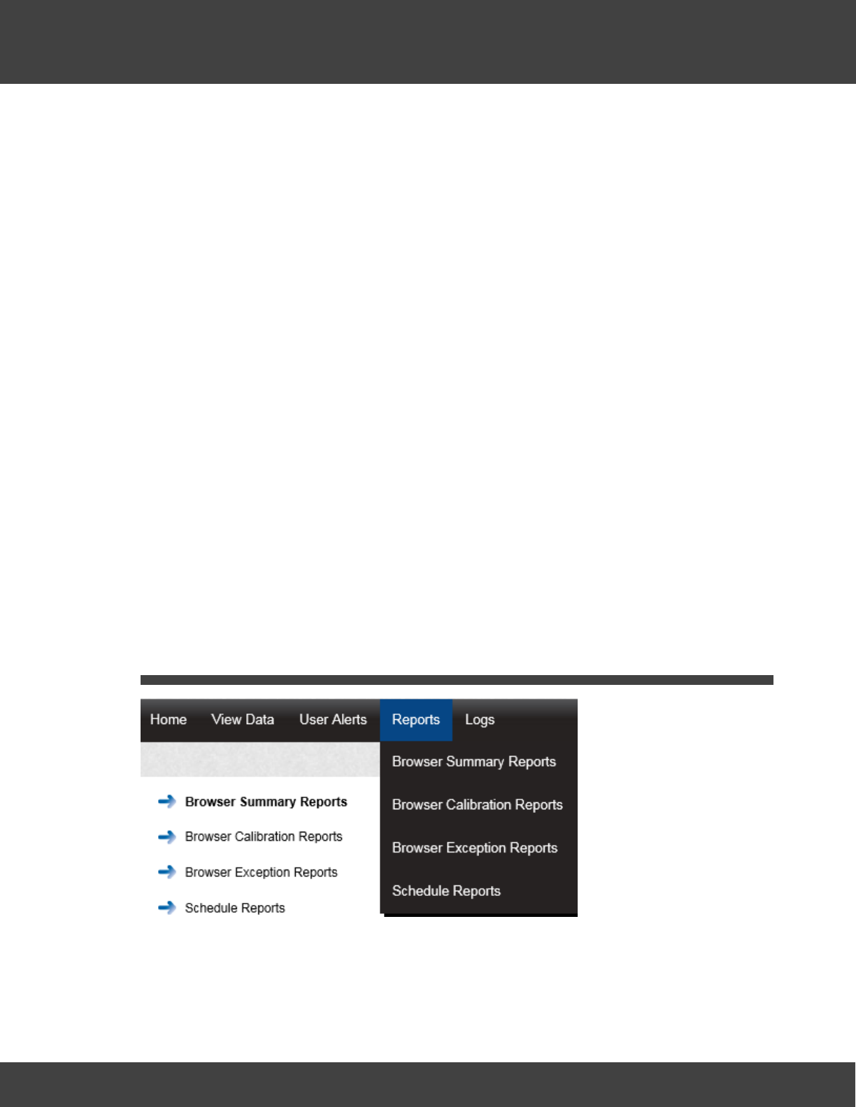
200
Notion Pro © 2017 IMC Group Ltd HP5525 Version 1.2.15
Reference Section
Alarm will be generated on the system, if the Alarm conditions have returned to normal the
amber Alarm icon will be removed from the list.
When selecting Time Out a default message “Time Out was selected for this Alarm”
will be entered into the Alarm Notes dialog box. This can be added to or overwritten.
Return to Acceptable Conditions
If Return to Acceptable Conditions is selected, as soon as you select Submit the
Alarm will be acknowledged as soon as the conditions return to normal limits. The amber
Alarm icon will remain until the conditions return to normal limits.
When selecting Return to Acceptable Conditions a default message “Return to
Acceptable Conditions was selected for this Alarm” will be entered into the Alarm
Notes text box. This can be added to or overwritten.
Timed Reset Override
This feature allows you to defer the Alarm reset until a date in the future. To enter the
required date select the calendar icon and select the date. This will be entered in the dialog
box next to Reset Date. Select the time of day from the Hours and Minutes drop down
menus.
This feature would be used if for example the air conditioning in a room or space failed and
it was going to take several days to get an engineer in to carry out repairs. In this case the
Alarms would be going off all the time which is an inconvenience.
Using this feature requires you to manually enter a note into the Alarm Notes text box. A
suitable note might be “Engineer called to repair Humidifier unable to attend site before next
Friday”
When happy with the details select Submit.
5.8 Setting Up and Running Reports
Notion Pro can produce a variety of Reports. These can be tailored to your individual
specifications. The report will be in PDF format with the option to have a CSV data file
attached.
Scheduled Reports are user configurable and once configured to be auto generated on a

201
Notion Pro © 2017 IMC Group Ltd HP5525 Version 1.2.15
Reference Section
daily, weekly or monthly basis and sent to the user by email. The on-screen reports can be
downloaded and saved in PDF format.
The topics in this section give detailed instructions on how to set up and run data Reports
for the sensors on your Site.
5.8.1 Summary Reports
(Reports>Browser Summary Reports)
These can be divided into two sub-types:
-Sensor Reports - Summaries of data collected over the past week by selected
sensors. You can also generate Reports for sensors of a selected type (temperature
for a Temperature Sensor, current for an Energy Sensor etc.) over a specified date
range (the past week by default).
-Zone Reports - Summaries of data collected by all Sensors in a given Zone for a
specified date range.
To generate a Summary Report:
1. Select Reports>Browser Summary Reports to give the Summary Report dialog box,
see below for example.
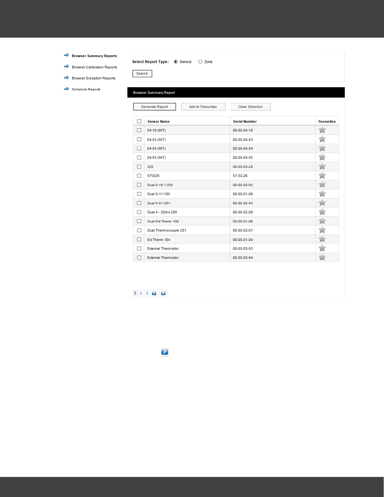
202
Notion Pro © 2017 IMC Group Ltd HP5525 Version 1.2.15
Reference Section
The sensor list is for all sensors of all types across your Site. To report on one or more
Sensors:
i. Ensure that the Sensor option button is selected.
ii. Select the sensor(s) of interest from the Sensor Name list. If the list of sensors is long
you may need to click on to see the next page in the sensor list. To select all
sensors in the list simply click in the tick box next to Sensor Name at the top of the
list.
iii. Select Generate Report .
This gives a report in .pdf format. For example, see example below:
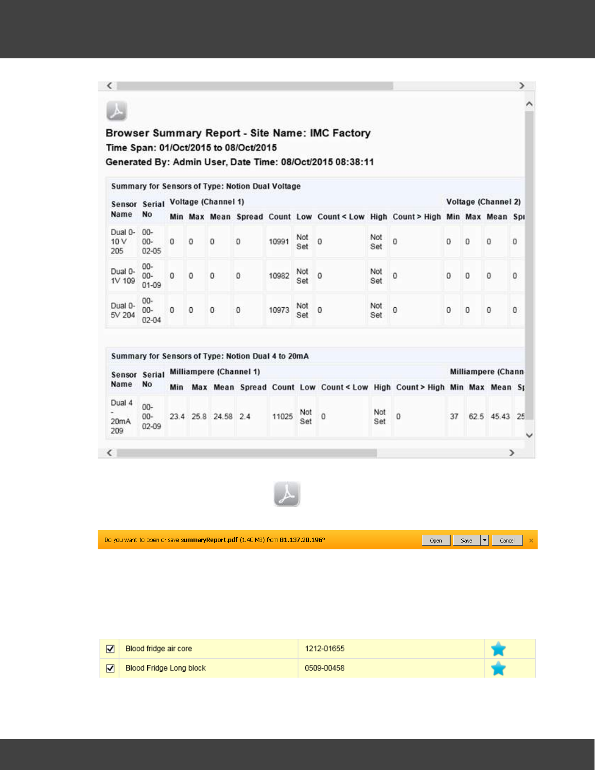
203
Notion Pro © 2017 IMC Group Ltd HP5525 Version 1.2.15
Reference Section
Note that you need to use the scroll bar at the top (or bottom) to see all of the Report. If
you wish to save the report, click on to give the standard browser 'Save' dialog box
(example below is for Internet Explorer): :
Select Save or Save as to save the .pdf file to the required location.
There may be sensors that you often wish to report on. You can specify these as
‘favourite’ sensors. To do this, select the grey star symbol next to the sensors of interest.
The star colour changes to blue and the row containing the sensor becomes highlighted. See
below for example:
Having specified your ‘favourite’ sensors, select Add to Favourites. If you then nominate
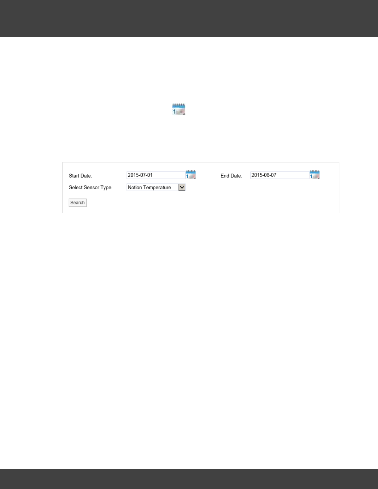
204
Notion Pro © 2017 IMC Group Ltd HP5525 Version 1.2.15
Reference Section
other sensors as ‘favourites’ select the grey start for the sensors of interest then select
Update Favourites .
Your favourite sensors will then move to the top of the Sensor List and Generate
Summary Report will then generate a report for your favourite sensors.
Having generated a Report, to generate Summary Reports for a selected sensor type over
a specified date range, first use the icon to choose the required Start and End dates
(or enter the required dates directly into the Start Date and End Date boxes), then select
the required sensor type from the Select Sensor Type pull-down list. Click Search to
generate the specified Report.
Note: you will only see the date range selection controls:
after you have already generated a Report.
To report on a Zone, ensure that the Zone option button is selected. Click Search to
generate a list of Zones for your Site. See below for example.
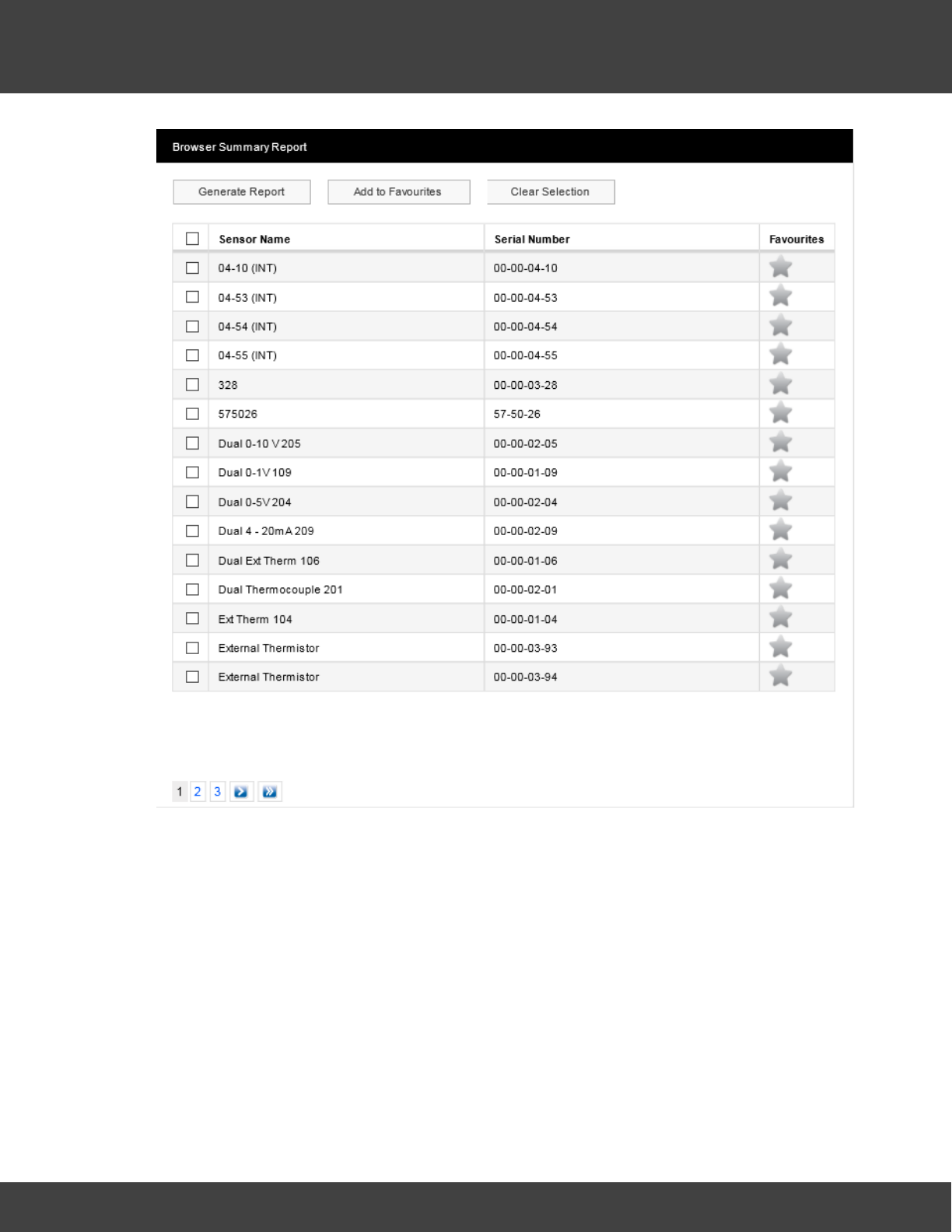
205
Notion Pro © 2017 IMC Group Ltd HP5525 Version 1.2.15
Reference Section
To generate a report for all sensors in a Zone simply select the Zone of interest from Zone
Name list then select Generate Report. You can select ‘favourite’ Zones, or sensor types
and date ranges using the same methods as detailed above for sensors.
5.8.2 Calibration Reports
(Reports>Browser Calibration Reports)
A simple report of sensors that need calibrating on a given date. This is one month from
today’s date by default, but the example below shows sensors due for calibration within one
year of the current date.
For example:
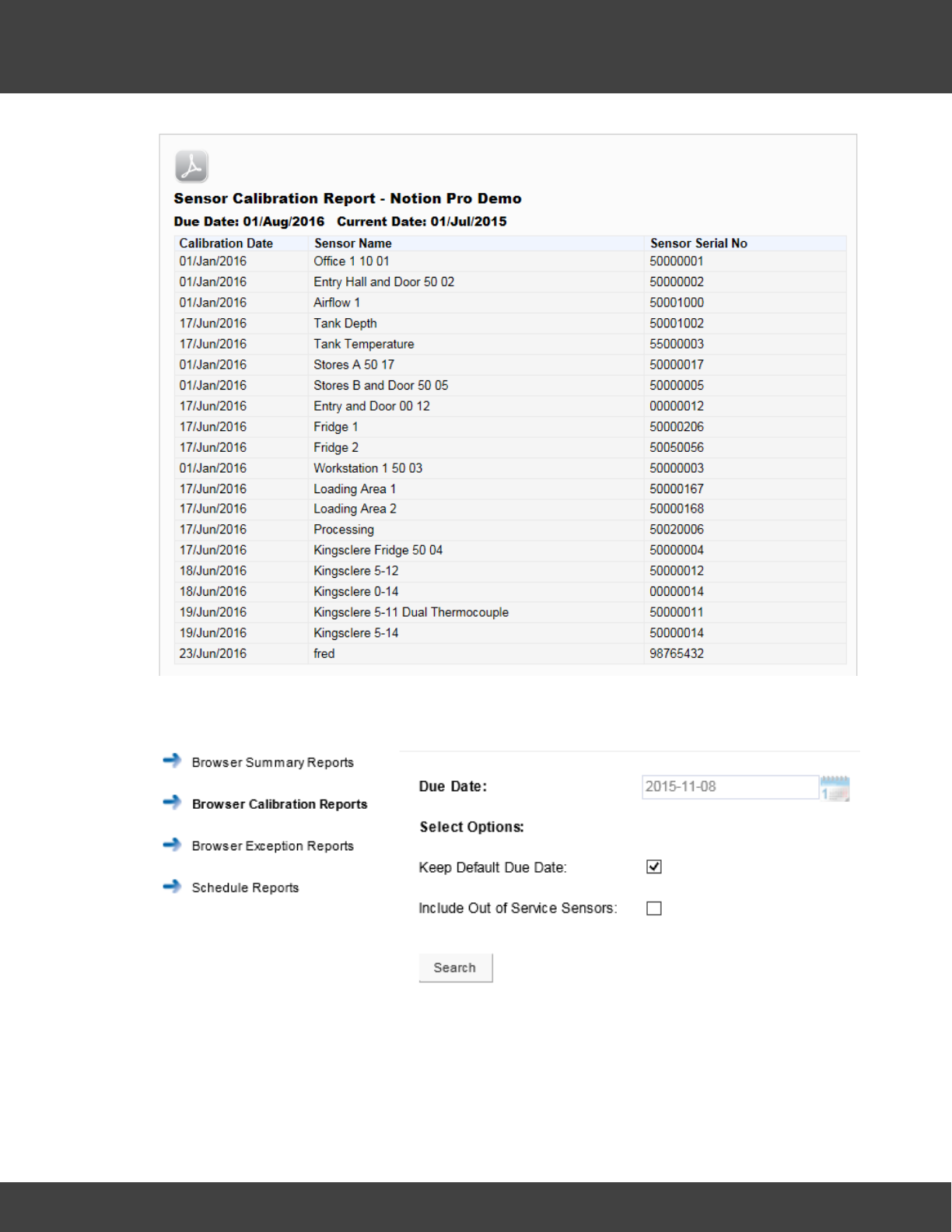
206
Notion Pro © 2017 IMC Group Ltd HP5525 Version 1.2.15
Reference Section
To generate a Calibration Report select Reports>Browser Calibration Reportins, see
below:
By default, a Report will be generated for all sensors which need to be calibrated one month
from today's date. If you wish to select a different due date, clear the ‘Keep Default Due
Date’ tick box then click the Due Date calendar and select the required date. There may be
Sensors on your Site which are out of service, but may still be due for calibration. If you
wish to include such sensors in the Report select 'Include Out of Service Sensors' tick box if.
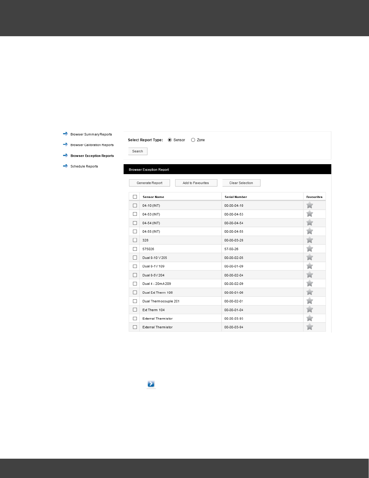
207
Notion Pro © 2017 IMC Group Ltd HP5525 Version 1.2.15
Reference Section
Click Search to generate the specified Report.
5.8.3 Exception Reports
(Reports>Browser Exception Reports)
Reports of ongoing alarm conditions, by Sensor or by Zone.
For example:
The sensor list is for all sensors of all types across your Site. To report on one or more
Sensors:
1. Ensure that the Sensor option button is selected.
2. Select the sensor(s) of interest from the Sensor Name list. If the list of sensors is long
you may need to click on to see the next page in the sensor list. To select all
sensors in the list simply click in the tick box next to Sensor Name at the top of the list.
3. Select Generate Report.
This gives a report in .pdf format. See below for example.
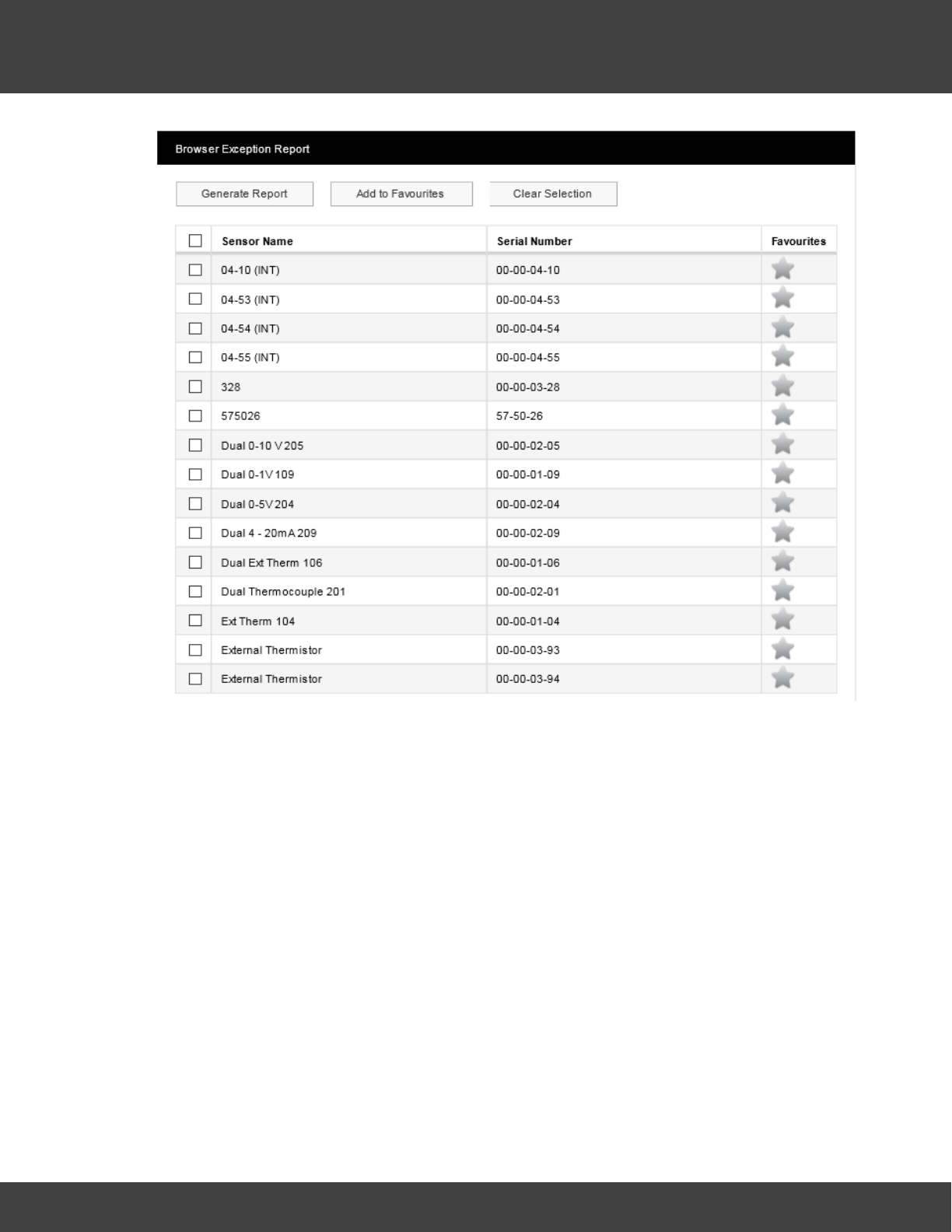
208
Notion Pro © 2017 IMC Group Ltd HP5525 Version 1.2.15
Reference Section
This gives a report in .pdf format. See below for example.
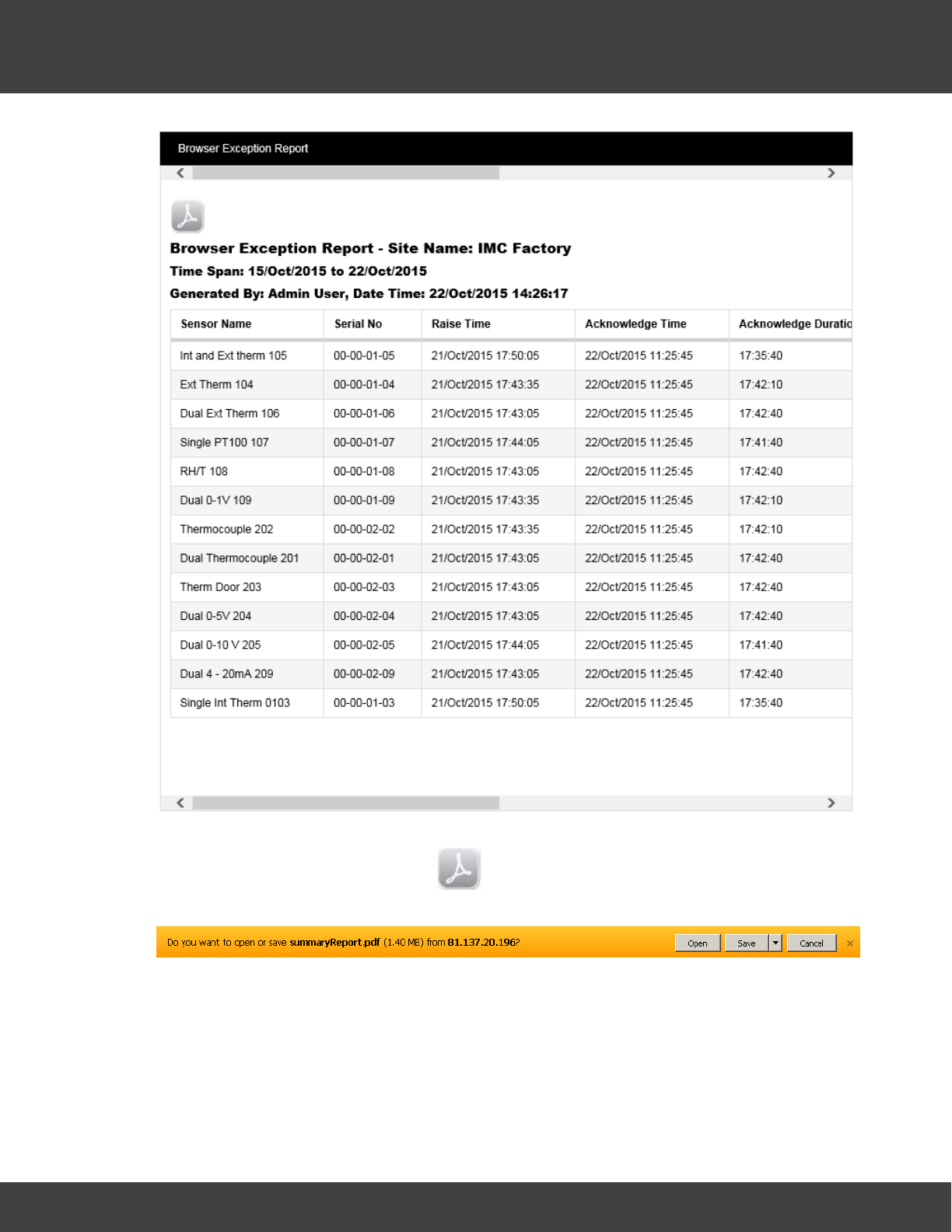
209
Notion Pro © 2017 IMC Group Ltd HP5525 Version 1.2.15
Reference Section
Note that you need to use the scroll bar at the top (or bottom) to see all of the Report. If
you wish to save the report, click on to give the standard browser Save dialog box
(example below is for Internet Explorer):
Select Save or Save as to save the .pdf file to the required location.
There may be sensors that you often wish to report on. You can specify these as
‘favourite’ sensors. To do this, select the grey star symbol next to the sensors of interest.
The star colour changes to blue and the row containing the sensor becomes highlighted. See
below for example:
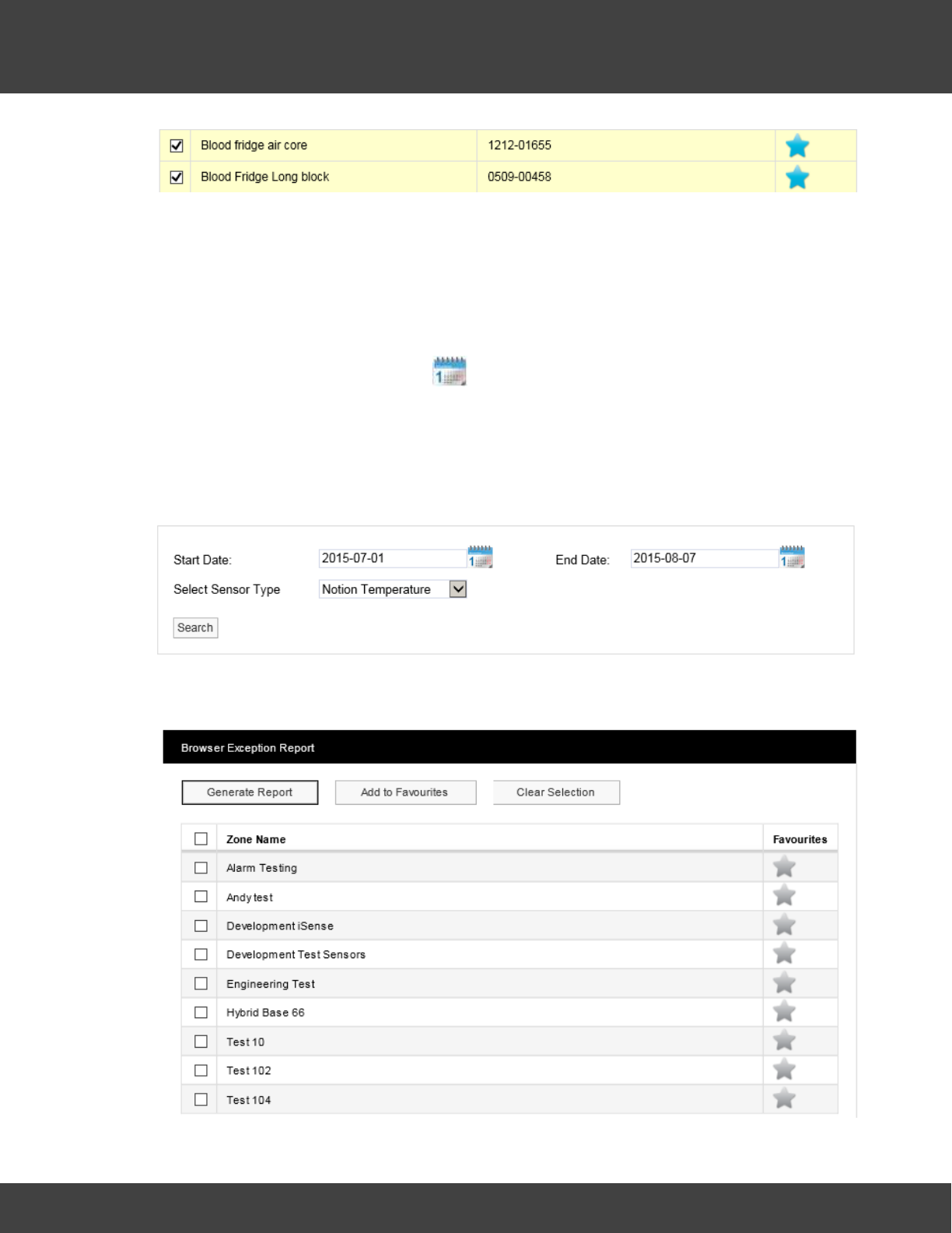
210
Notion Pro © 2017 IMC Group Ltd HP5525 Version 1.2.15
Reference Section
Having specified your ‘favourite’ sensors, select Add to Favourites. If you then nominate
other sensors as ‘favourites’ select the grey start for the sensors of interest then select
Update Favourites.
Your favourite sensors will then move to the top of the Sensor List and Generate
Exception Report will generate a report for your favourite sensors.
Having generated a Report, to generate Exception Reports for a selected sensor type over
a specified date range, first use the icon to choose the required Start and End dates
(or enter the required dates directly into the Start Date and End Date boxes), then select
the required sensor type from the Select Sensor Type pull-down list. Click Search to
generate the specified Report.
Note: you will only see the date range selection controls after you have already generated
a Report.
To report on a Zone, ensure that the Zone option button is selected. Click Search to
generate a list of Zones for your Site. See below for example.

211
Notion Pro © 2017 IMC Group Ltd HP5525 Version 1.2.15
Reference Section
To generate a report for all sensors in a Zone simply select the Zone of interest from Zone
Name list then select Generate Report. You can select ‘favourite’ Zones, or sensor types
and date ranges using the same methods as detailed above for sensors.
5.8.4 Scheduled Reports
(Reports>Schedule Reports)
These cover a variety of Report types, which can be set up to start and end at predefined
dates/times and can run at predefined intervals.
For example:
The above would generate .pdf report which would be emailed to the System Contact
user(s). See below.
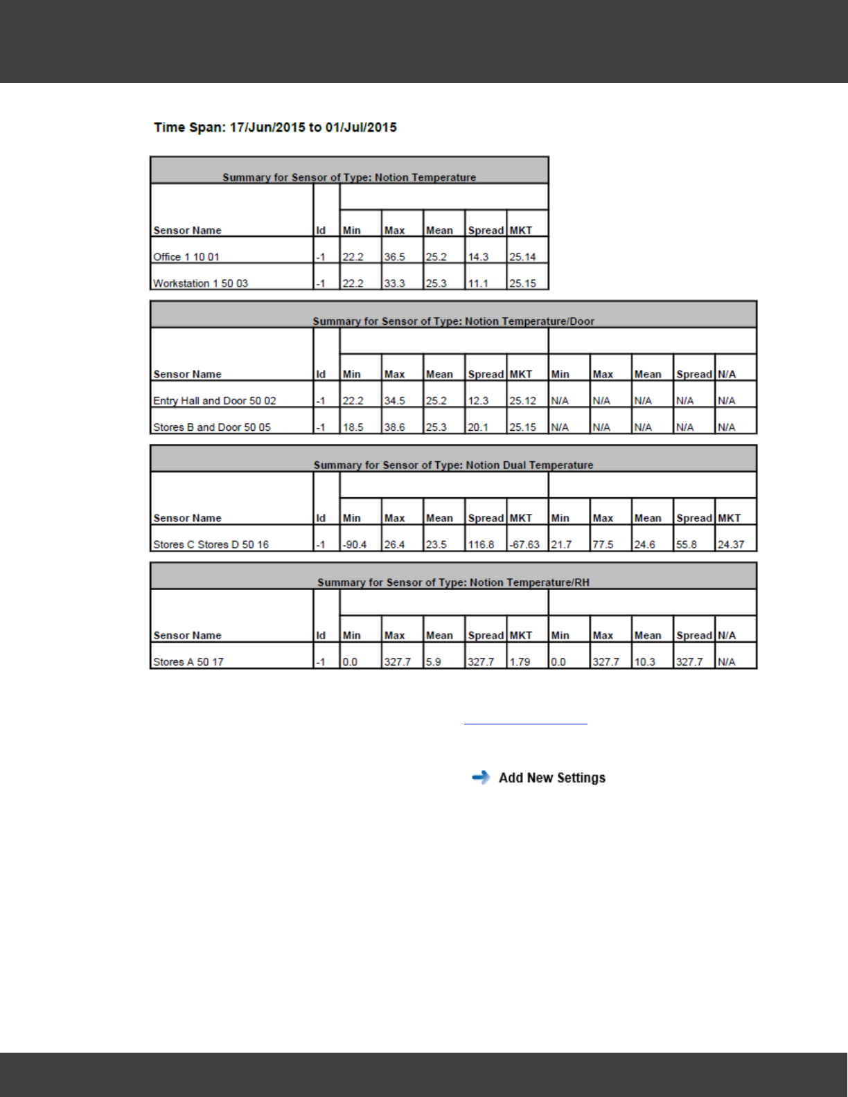
212
Notion Pro © 2017 IMC Group Ltd HP5525 Version 1.2.15
Reference Section
The Sensors to be reported on and the Contacts who are to be emailed the report are
defined in a similar way to the method used for Email Alert Groups.
As an example, the steps to set up and run the Scheduled Report shown above might be:
1. Select Reports>Schedule Reports. Note on the side menu is
highlighted – we are defining a new Report.
2. Select Summary Report from the Report Type: pull-down list.
3. Enter a title for the Report in the Report User Title box, for example ‘Sys Admin
Summary Report’.
4. Select a date and time for the first Report run using the First Report Run: controls. This
should be later today or any time in the future.
5. Report Interval is the length of time between repeated runs of the Report, for example
an interval of one day would give daily Reports. You don’t have to specify a Report
Interval, this would give a ‘one off’ Report.
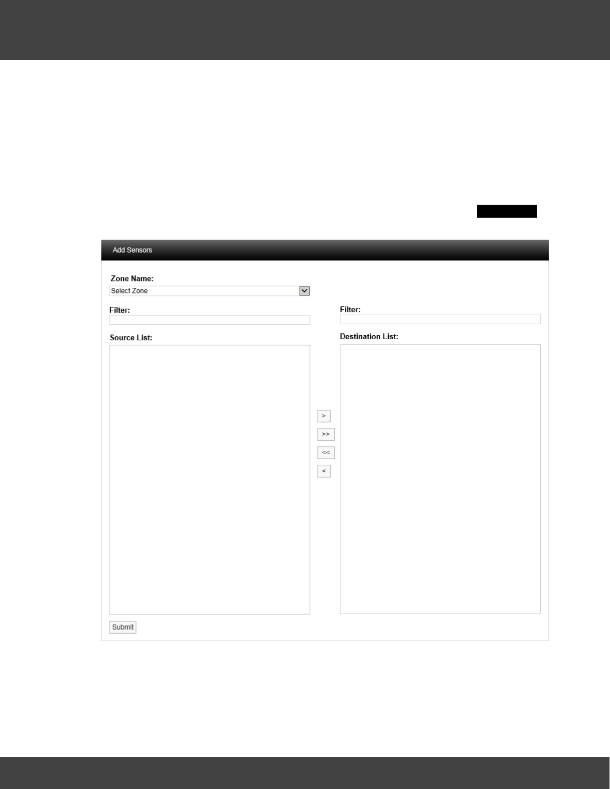
213
Notion Pro © 2017 IMC Group Ltd HP5525 Version 1.2.15
Reference Section
6. Use the Report Start: and Report End: controls to specify the time span for the Report.
This would typically be dates in the past, but could be dates in the future (although if,
for example you specified a start date one week in the future and end date two weeks
in the future you would have to wait 2 weeks before you saw a Report). In our example
17 June 2015 has been set at the start date, 1 July 2015 as the end date.
Note: you should set an Interval, with no Report Start or Report End time, or a Report
Start and Report End time, (but no Interval).
7. Having set up the Report dates, we now need to specify the Sensor data that we wish
to report on. Click the Sensors tab, then click Add Sensors to give the Add Sensors
dialog box, see below for example:
8. Select the Zone that contains the sensors you wish to report on from the Zone Name
pull-down list. The Source List becomes populated with the sensors in the selected
Zone. See below for example:
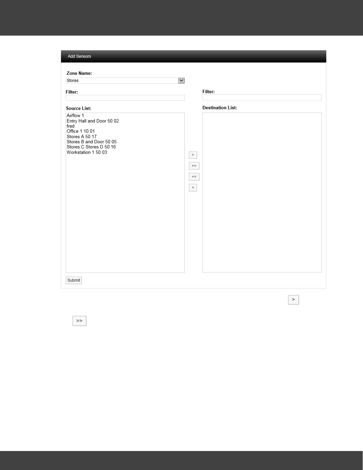
214
Notion Pro © 2017 IMC Group Ltd HP5525 Version 1.2.15
Reference Section
9. Select a sensor in the Source List that you wish to report on, and select to
transfer it to the Destination List. To transfer all sensors in a single operation click
. When the Zone Name list is long the required Zone can be found by using the
Filter. See below for an example of a populated Destination List.
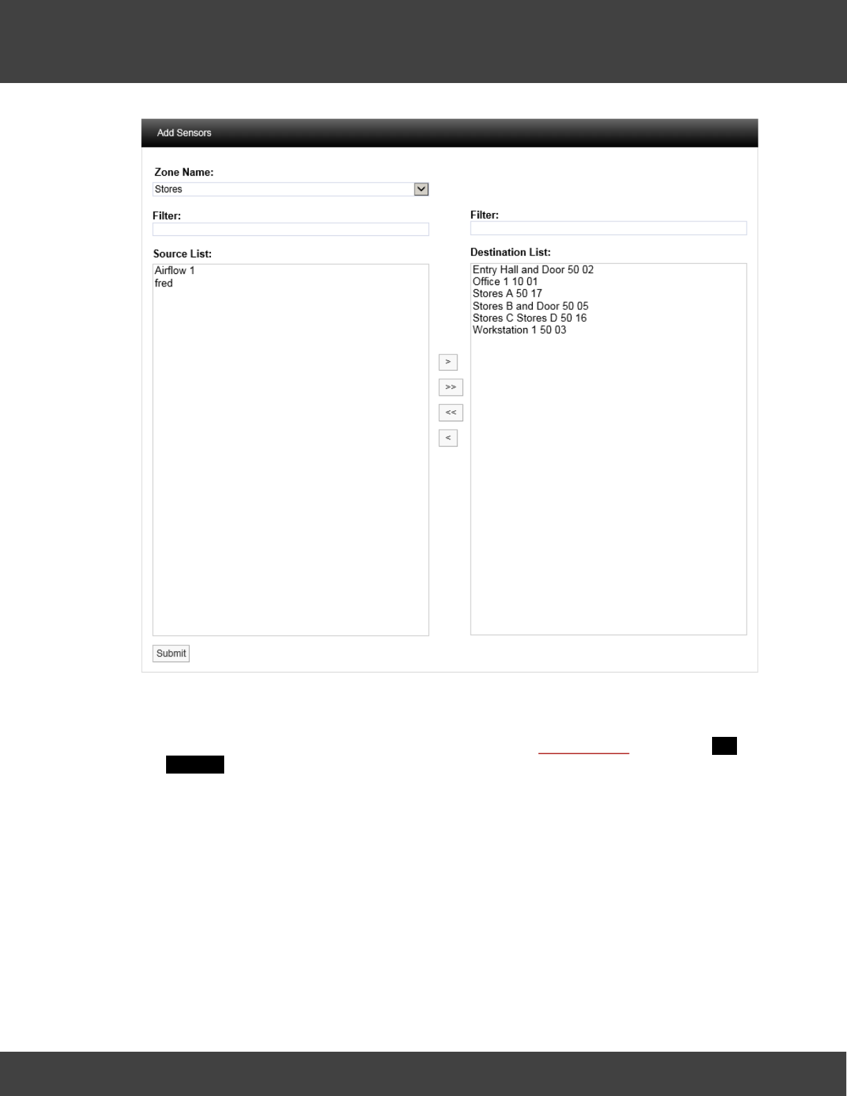
215
Notion Pro © 2017 IMC Group Ltd HP5525 Version 1.2.15
Reference Section
10. When satisfied with your selections, select Submit.
11. Now we need to specify a list of Users (System Contacts) that the report will be
emailed to. Click the System Contacts tab, then click Add Contacts to give the Add
Contacts dialog box. See below for details.
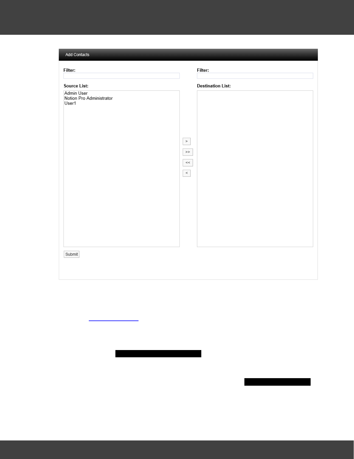
216
Notion Pro © 2017 IMC Group Ltd HP5525 Version 1.2.15
Reference Section
12. Populate the Destination List for System Contacts using the same methods that
you used to populate the Destination List for Sensors (see step 9 above). When
satisfied with your selections click Submit .
13. If any External Contacts have been set up and you wish to send the Report to them,
select the External Contacts tab and populate and Submit it in the same way as for
System Contacts.
14. When satisfied with all of your Report Settings, select Submit or Submit and Run
Now under the Add Scheduled Report Settings banner. Submit and Run Now button
is used to generate reports immediately; however some delay can be expected if a
large report is submitted.
The Scheduled Report you have defined will now be added to the View Scheduled Reports
window. See below.
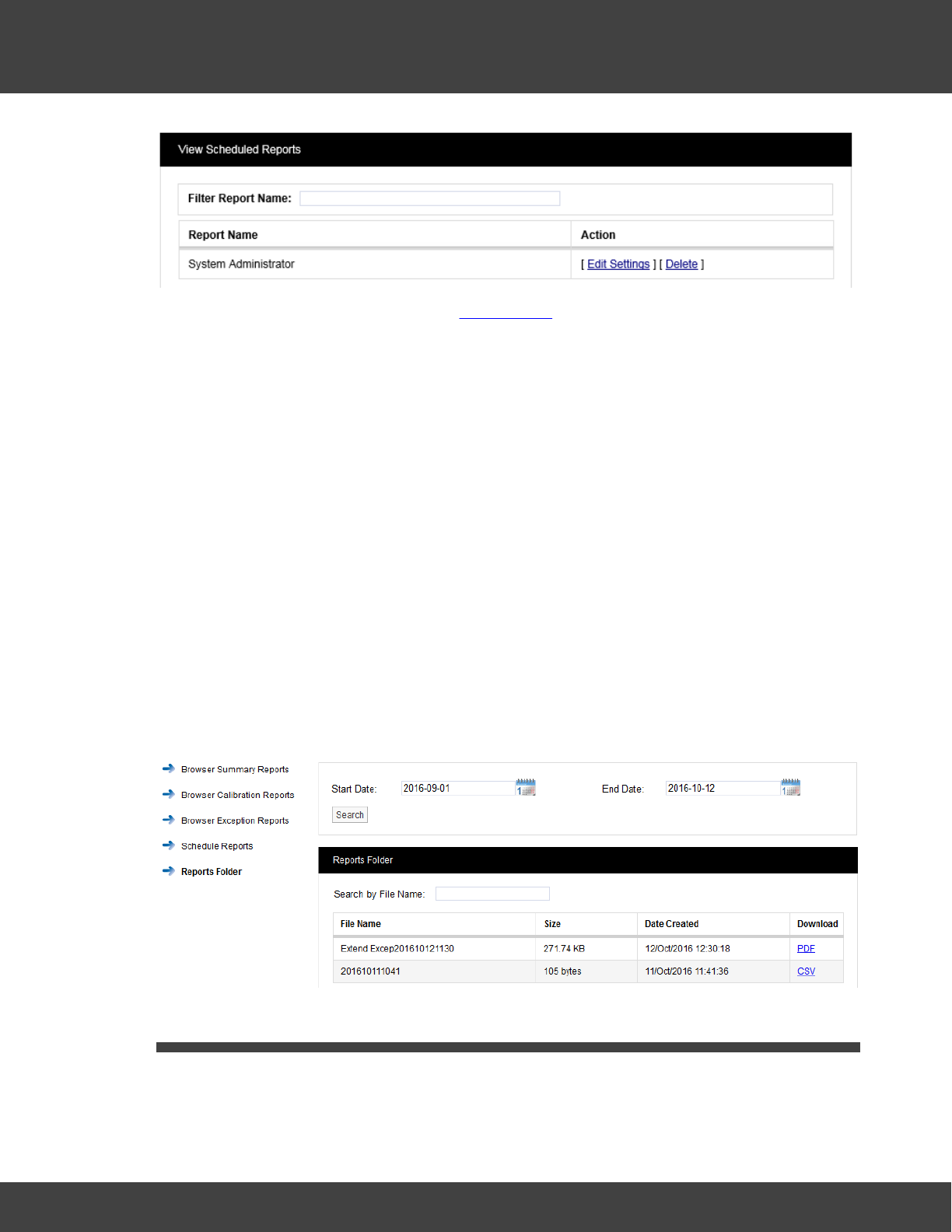
217
Notion Pro © 2017 IMC Group Ltd HP5525 Version 1.2.15
Reference Section
To change the Report settings, click on Edit Settings.
Note: If your Email Server has been set up to limit the maximum allowed email/attachment
size, then Scheduled Reports in excess of the size limit will be blocked by your Email
Server. Note that because there is no standard mechanism for feeding this
eventuality back to the email client, Notion Pro cannot know that these emails have
been blocked by the server. Most Email Servers inform the sender of this situation
by placing a message in the sender account's Inbox. If Scheduled email Reports are
not being sent, check the Inbox for the sender account you set up in Notion Pro.
5.8.5 Reports Folder
(Reports>Reports Folder)
This section display Scheduled reports saved in the Reports Folder, users can view or
save the report by clicking the hyperlink provided under Download. The Reports folder
needs to be set-up first by using Notion Pro Config utility otherwise reports will not be
displayed. In order to refine the search use two calendars to select a Start and End Date
and select Search. All scheduled reports generated between these dates will be displayed,
see Figure below. A particular file can be searched quickly by entering first few characters of
the file name in Search by File Name input field.
5.9 Viewing System Logs
The options under this menu enable you to view the System Logs.
Notion Pro has a series of System Logs for keeping track of critical events such as system
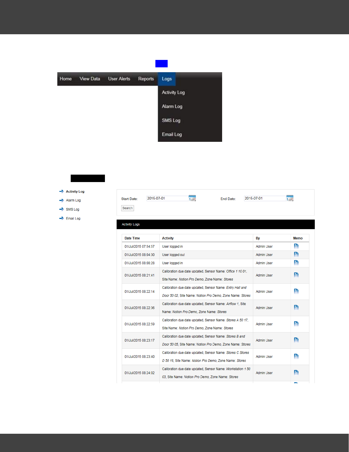
218
Notion Pro © 2017 IMC Group Ltd HP5525 Version 1.2.15
Reference Section
activity, alarm activity and SMS activity.
To access the System Logs select Logs from the main menu, see below.
5.9.1 Activity Logs
The Activity Log contains all the user activity on the system such as logging in and out
and editing. To access the Activity Log select Logs>Activity Log from the main menu.
The Activity Logs window appears, see below.
The Activity Log follows system events. Each entry is date and time stamped with a
description of the action carried out or activity and the user.
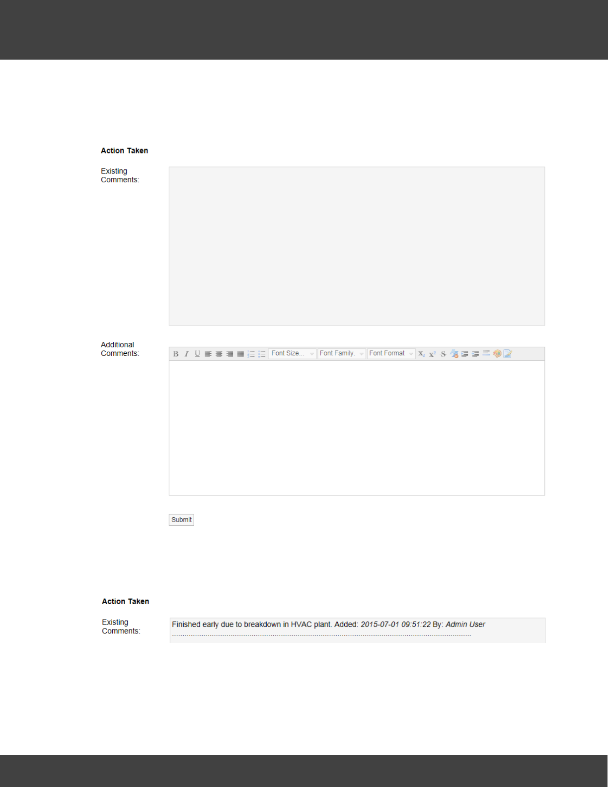
219
Notion Pro © 2017 IMC Group Ltd HP5525 Version 1.2.15
Reference Section
There is a Memo field that may or may not contain any memos, for example an activity
such as User logged out would not have a memo as it is created by the system when the
user logs out. If required you can select the memo icon next to an activity and add a
memo. See below.
When happy with memo select Submit.
The memo will now be saved in the top section under existing comments. These comments
are date and time stamped and are identified by user and are now not editable, see below.
Additional comments can be added at any time.
To search back through previous Activity Logs use the Search function, see below.
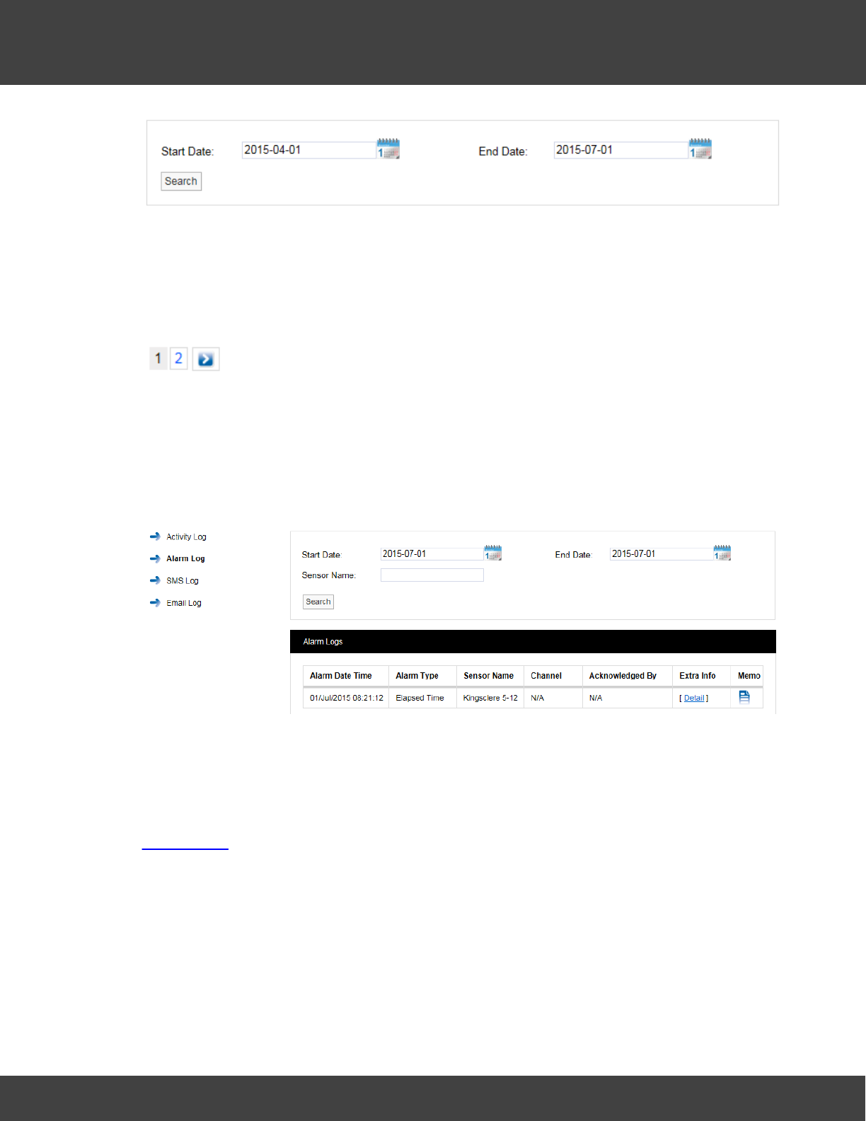
220
Notion Pro © 2017 IMC Group Ltd HP5525 Version 1.2.15
Reference Section
Use the two calendars to select a Start Date and End Date and select Search. All Activity
Logs between these dates will be displayed.
To move through available log pages, use the blue left and right arrows at the bottom of
the page. The single blue arrows will step through one page at a time, the double blue
arrows will take you to either the first page or the last page of the search, see below.
5.9.2 Alarm Logs
The Alarm Log contains all the alarm activity on the system. To access the Alarm Log
select Logs>Alarm Log from the main menu. The Alarm Logs window appears, see
below.
The Alarm Log contains date and time stamped data, Alarm Type, Sensor Name,
Channel, Acknowledged By, Extra Info and a Memo. Extra Info is a link to a floating
tip, the tip contains Site and Zone name information.
The Memo contains information on alarm reasons and action taken. Additional notes can be
added at any time. These notes are not editable. Notes are added by following the steps in
Activity Logs.
More Alarm Logs can be viewed by using the calendar Search function.
To move through available Alarm Log pages, use the blue left and right arrows at the
bottom of the page. The single blue arrows will step through one page at a time. The
double blue arrows will take you to either the first page or the last page of the search.
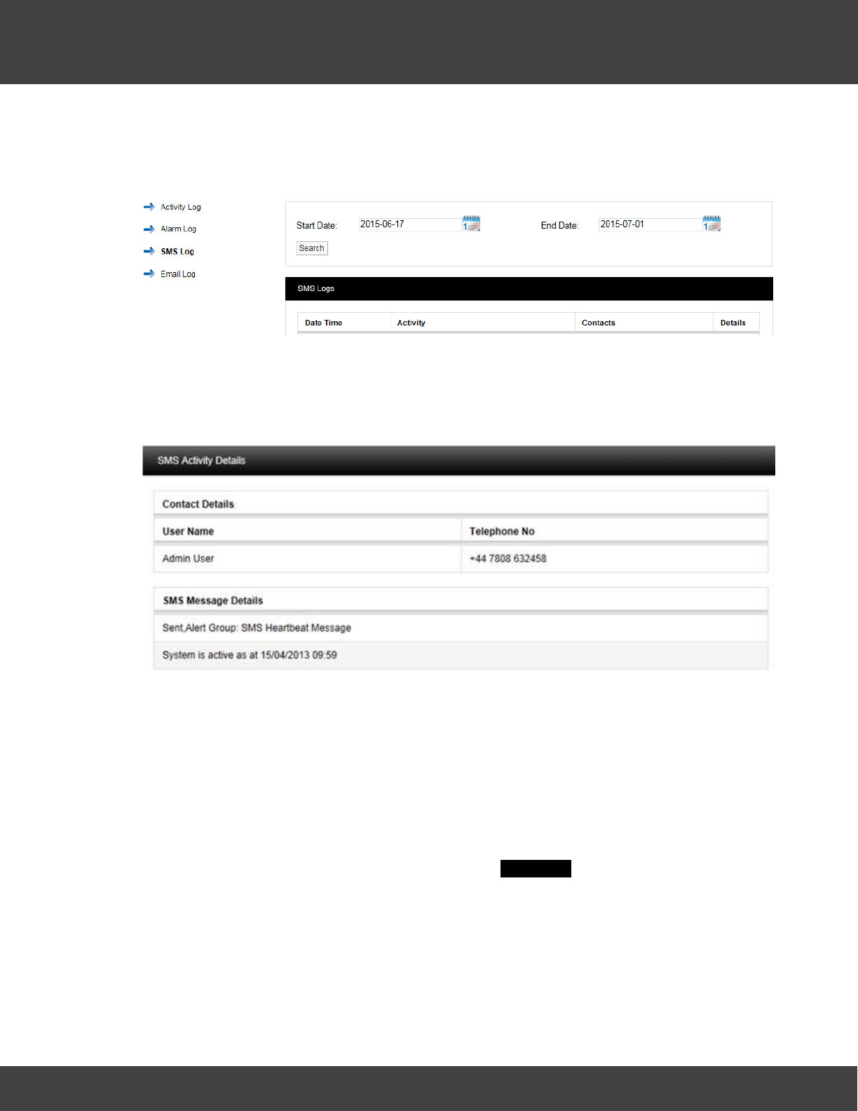
221
Notion Pro © 2017 IMC Group Ltd HP5525 Version 1.2.15
Reference Section
5.9.3 SMS Logs
The SMS Log contains entries for all system SMS activity. To access the SMS Log, select
Logs>SMS Log from the main menu. The SMS Logs window appears, see below.
The SMS Log contains date and time stamped data, Activity details, Contacts and a
Details or memo field.
The SMS Details contains details of the message sent including User name and the contact
number that the SMS message was delivered to, see below.
The example shown above SMS is a regular system heartbeat message sent to the Admin
User. More SMS logs can be viewed by using the calendar search function.
To move through available SMS log pages, use the blue left and right arrows at the bottom
of the page. The single blue arrows will step through one page at a time. The double blue
arrows will take you to either the first page or the last page of the search.
5.9.4 Email Logs
The Email Log contains entries for all system email activity. To access the Email Log,
select Logs>Email Log from the main menu. The Email Logs window appears, see below.
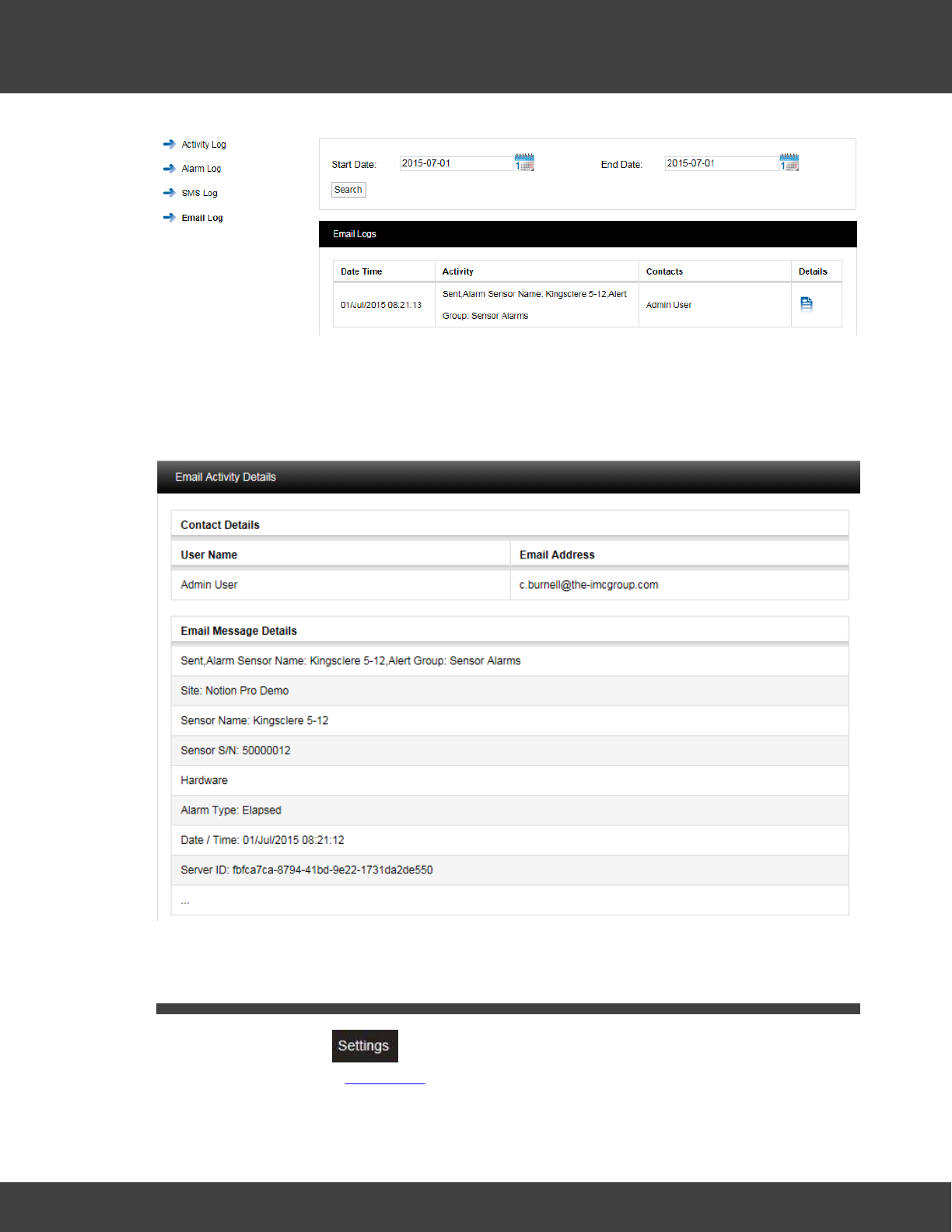
222
Notion Pro © 2017 IMC Group Ltd HP5525 Version 1.2.15
Reference Section
The Email log contains date and time stamped data, Activity details, Contacts and a
Details or memo field.
The Email Details contains details of the message sent including User name and the contact
email address that the Email was sent to, see below for example.
5.10 Settings
The options under the menu enable System Administrators to create Sensor
Groups and handle User Passwords.
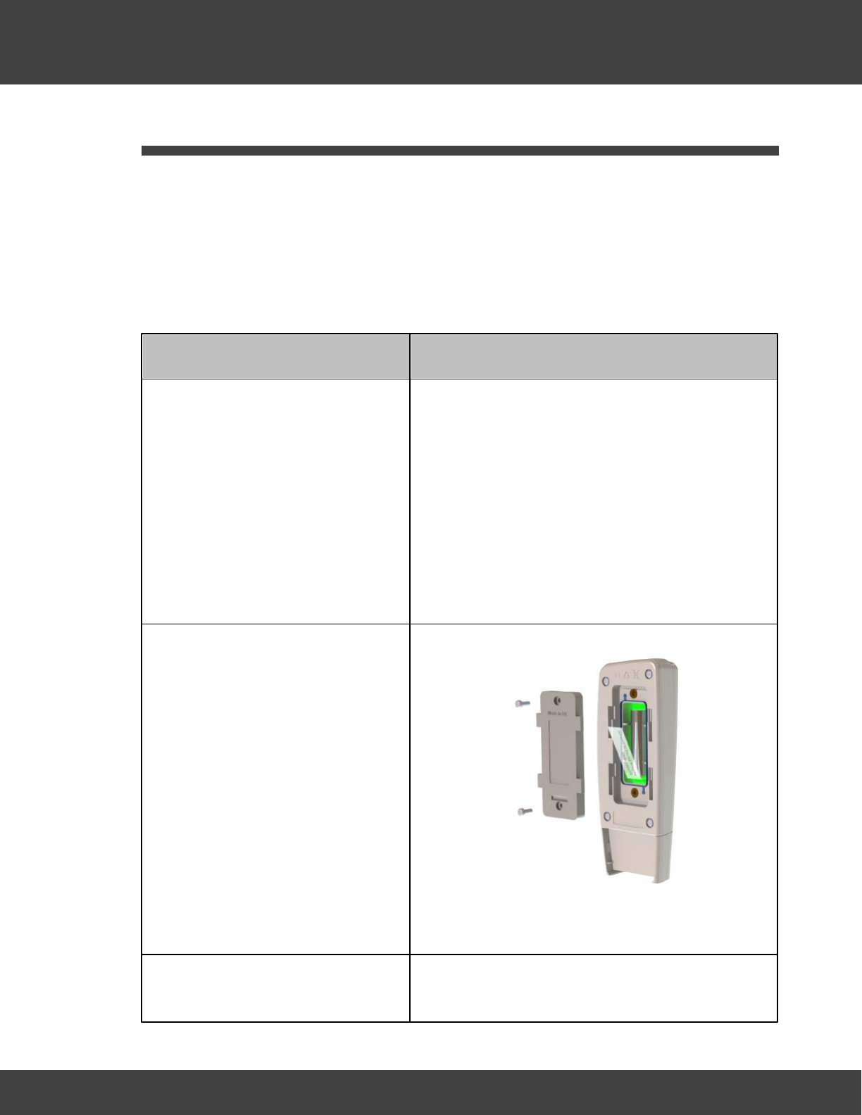
223
Notion Pro © 2017 IMC Group Ltd HP5525 Version 1.2.15
Reference Section
5.11 Adding Transmitters
Installing a Transmitter
As far as possible, the transmitter units should be placed where they will not be subject to
electromagnetic interference and where they will not be shielded by walls, doors, metal
furniture, appliances etc. They should also be mounted vertically to maximise radio range. A
wall-mounting bracket is available, IMC part no. N494.
Note: the procedure below must be followed for each Transmitter that you are installing.
Install Step
Notes
1. If you are NOT using the door
monitoring and alarm function
option with this transmitter, go to
step 2 below.
Secure a matching pair of door
monitoring and alarm function
sensor pads to the door and door
frame of your refrigerated/frozen
storage unit.
If you intend to the lay the Transmitter loosely in
the storage unit, ensure that you position the door
frame sensor pad such that the cable running from
the pad runs into the storage unit.
If you intend to wall-mount the Transmitter, ensure
that you position the door frame sensor pad such
that the cable running from the pad runs outside of
the storage unit.
Ensure that the pads meet perfectly when the door
is closed.
2. Pull away the contact tag on the
transmitter to ensure the battery
contacts and the transmitter
contacts meet.
A green light will flash briefly.
The sensors are powered by 1 x 1.5V Lithium AA
cells. Standard AA cells can be used, but are not
recommended.
3. If you do not intend to wall-
mount your transmitter, go to
(Transmitter is lying loosely in your storage unit.)
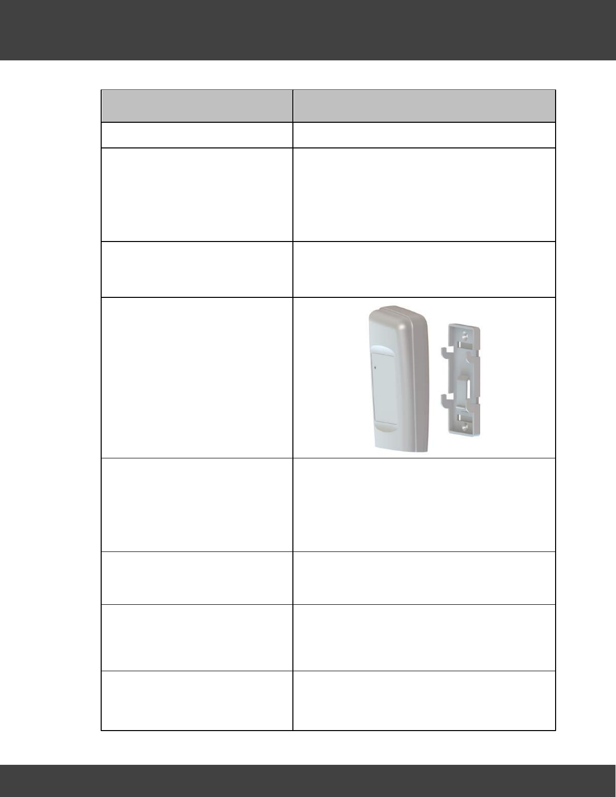
224
Notion Pro © 2017 IMC Group Ltd HP5525 Version 1.2.15
Reference Section
Install Step
Notes
step 11 below.
4. Drill holes for the Transmitter wall
mounting bracket into the wall at
an appropriate location.
When mounting the Transmitter bracket, you
should bear in mind that, if you are using the door
monitoring and alarm function and/or external
sensor options, you will need to run cables from the
Transmitter to your storage unit door frame sensor
pad and/or external sensor.
5. Screw the mounting bracket to
the wall.
As an alternative, the transmitter bracket could be
attached to a suitable post using cable ties. Slots
are provided in the bracket for this purpose.
6. Slot the Transmitter into the wall
bracket.
7. If you are using the door
monitoring and alarm function
option with this transmitter, route
the storage unit door frame
sensor pad cable up to the
transmitter.
8. If you are NOT using the
external sensor option, go to
step 11.
9. Place the external temperature
probe and associated cable at a
suitable position in your storage
unit.
10. Route the temperature probe
cable over the door frame and
up to the Transmitter.
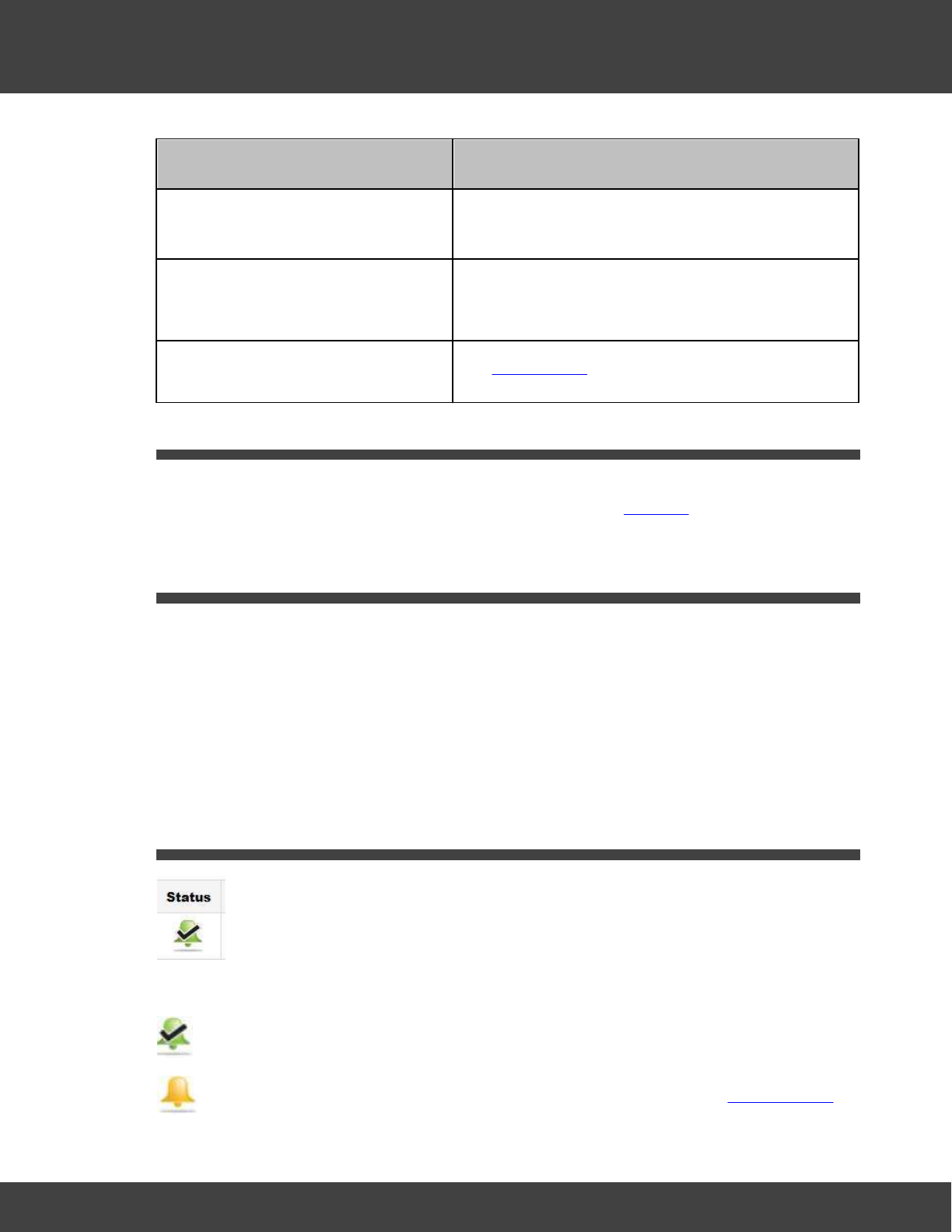
225
Notion Pro © 2017 IMC Group Ltd HP5525 Version 1.2.15
Reference Section
Install Step
Notes
Insert the cable into the
Transmitter.
11. Repeat steps 1-10 above for
each Transmitter that you are
adding.
12. Use Notion Pro to set up the
Transmitters for use.
See Add Sensors.
5.12 Backfill
If a transmitted signal can’t get through for some reason, data is stored in an on-board
cache. Backfill is where the transmitter is placed close to the ARB unit, stored data is then
transferred automatically to the ARB via RFID.
5.13 Adding Users - Before you Start
·You need to know how many Notion Pro Users there are on your Site, their names, email
addresses and the types of access they need to sensor data. If your installation includes
an SMS Module you also need to know users' mobile phone contact numbers.
·You need to be sure that your Notion Pro licence will allow you to create the number of
users necessary for your Site. Additional licences are available from IMC Group Ltd.
·It is assumed you know how to log in to Notion Pro and that you have System
Administrator rights.
5.14 Alarm Status
The symbols under Alarm mean:
Temperatures are within the levels that have been set.
Temperatures are outside the thresholds, but the alarm has been acknowledged.
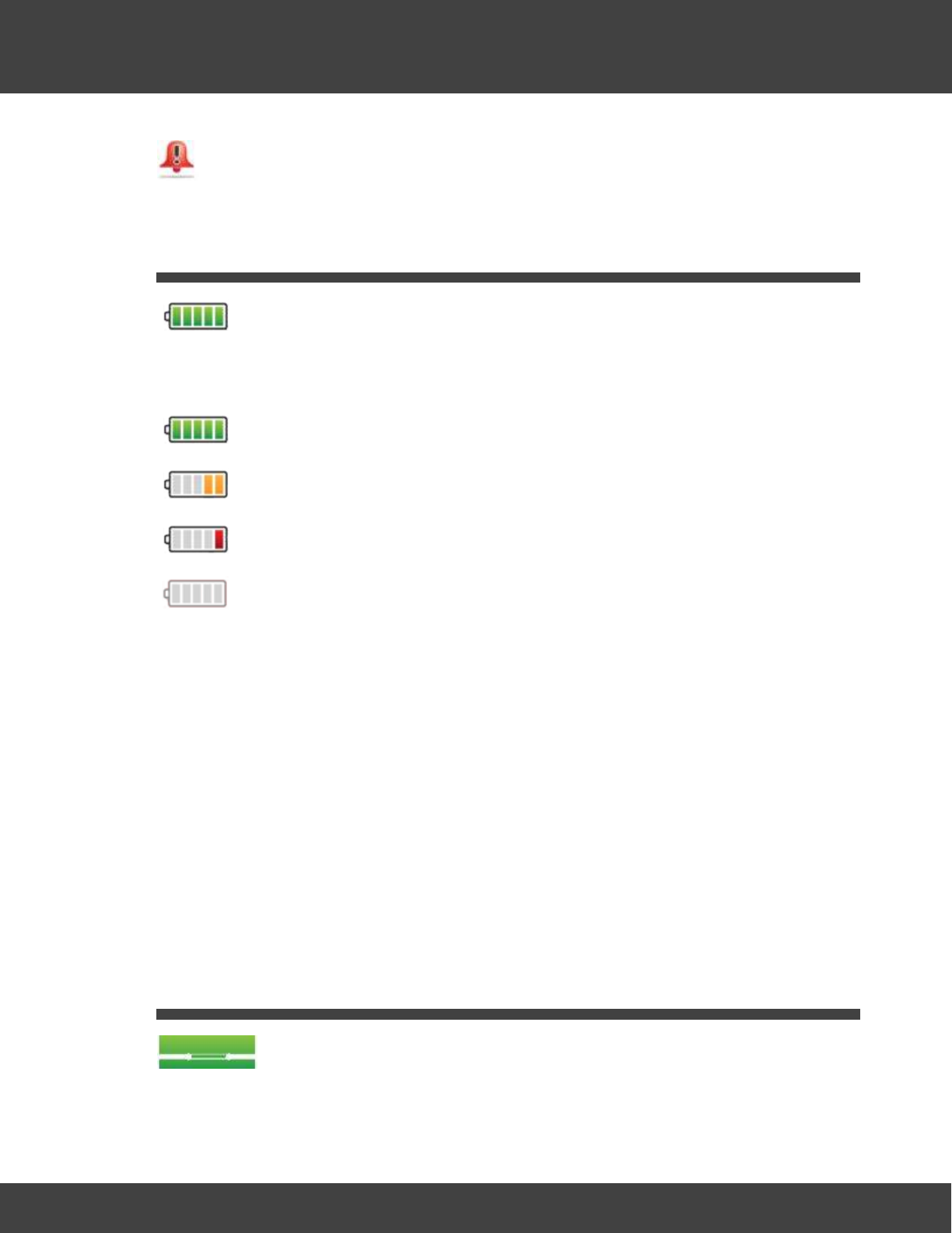
226
Notion Pro © 2017 IMC Group Ltd HP5525 Version 1.2.15
Reference Section
Temperatures are outside the thresholds, and the alarm has not been
acknowledged.
5.15 Battery
The symbols under Battery Level indicate the state of the battery for the associated
transmitter:
Battery is fully charged.
Battery has less than half its life left, but need not be replaced yet.
Battery is very low and should be replaced as soon as possible.
Battery is empty and must be replaced immediately.
Replacement Batteries
IMC recommends:
·Lithium - Energizer Ultimate Lithium L91 IMC stock No. G301
·Alkaline - Duracell ID1500-10 IMC stock No. 88705
Note: Alkaline batteries will work from +55ºC to -20ºC, but with greatly reduced life
compared to the Lithium cell IMC recommends. For example (all these figures are
approximate):
·40% life at 20ºC compared to equivalent Lithium
·20% at 0ºC
·5% or less at -20ºC.
5.16 Door Alarm
The symbols under Door Alarm indicate the door position for the storage unit being
monitored by the associated transmitter.
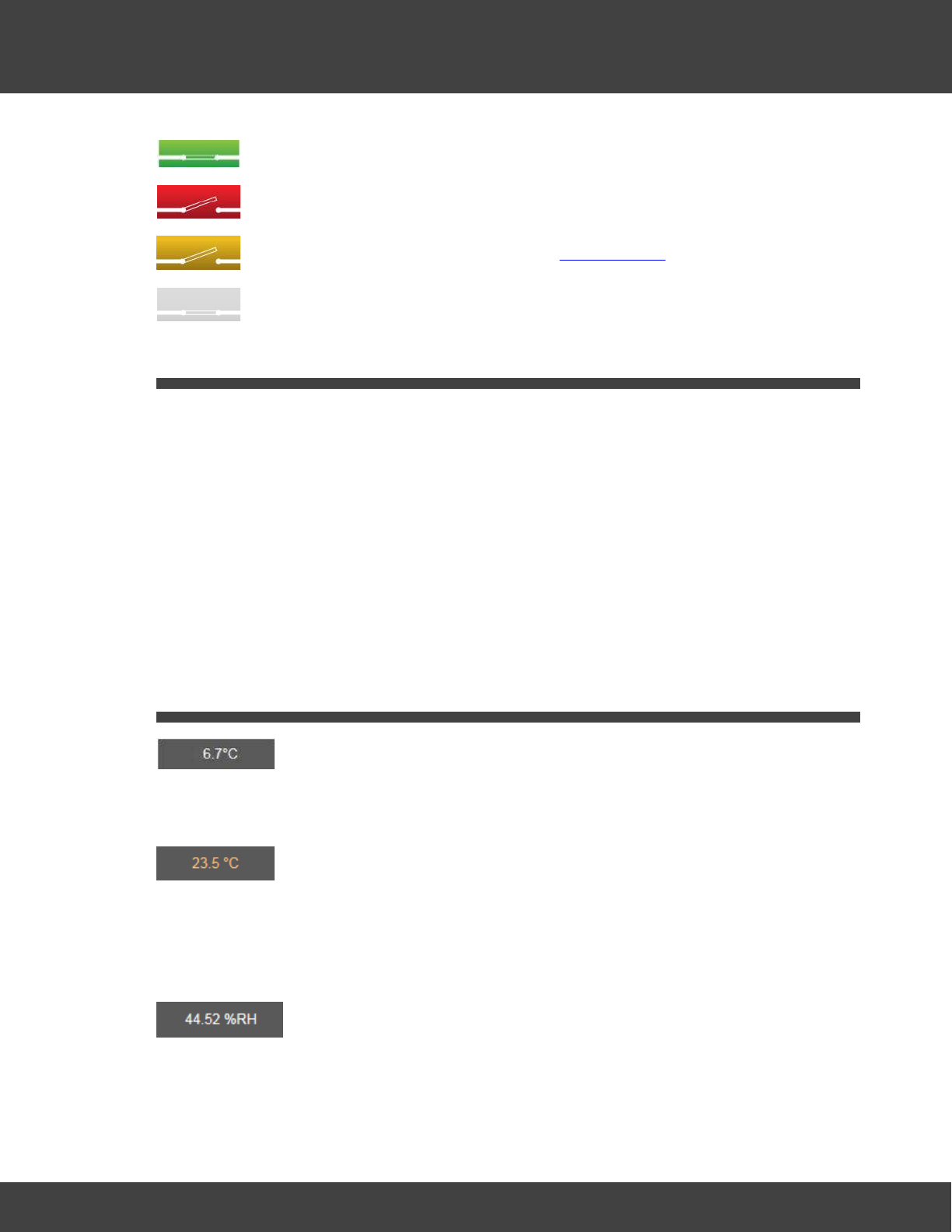
227
Notion Pro © 2017 IMC Group Ltd HP5525 Version 1.2.15
Reference Section
The door is closed.
The door is open and the alarm has not been acknowledged.
The door is open but the alarm has been acknowledged.
There is no door monitoring and alarm function associated with this transmitter.
5.17 Equipment Positioning
·Mount the Base Station vertically and away from metal as far as possible. Remember that
some walls may contain metal reinforcement, so fix to a masonry/plasterboard surface if
you can, or space the unit away from the wall
·Mount the transmitters vertically if you can. All transmitters can be wall-mounted or free
standing, as required. As far as possible, the transmitter units should be placed where
they will not be subject to electromagnetic interference and where they will not be shielded
by walls, doors, metal furniture, appliances etc.
·If the transmitters are vulnerable to physical disturbance then fix them in place to ensure
consistent performance.
·Repeater units can be supplied to increase effective range if needed.
5.18 Live Data
This is the last reading received from the transmitter.
A live data display icon such as:
indicates that the temperature has gone over the alarm threshold value, but the resulting
alarm has been acknowledged.
For a transmitter which has a Relative Humidity channel, a symbol such as the following
would be displayed:
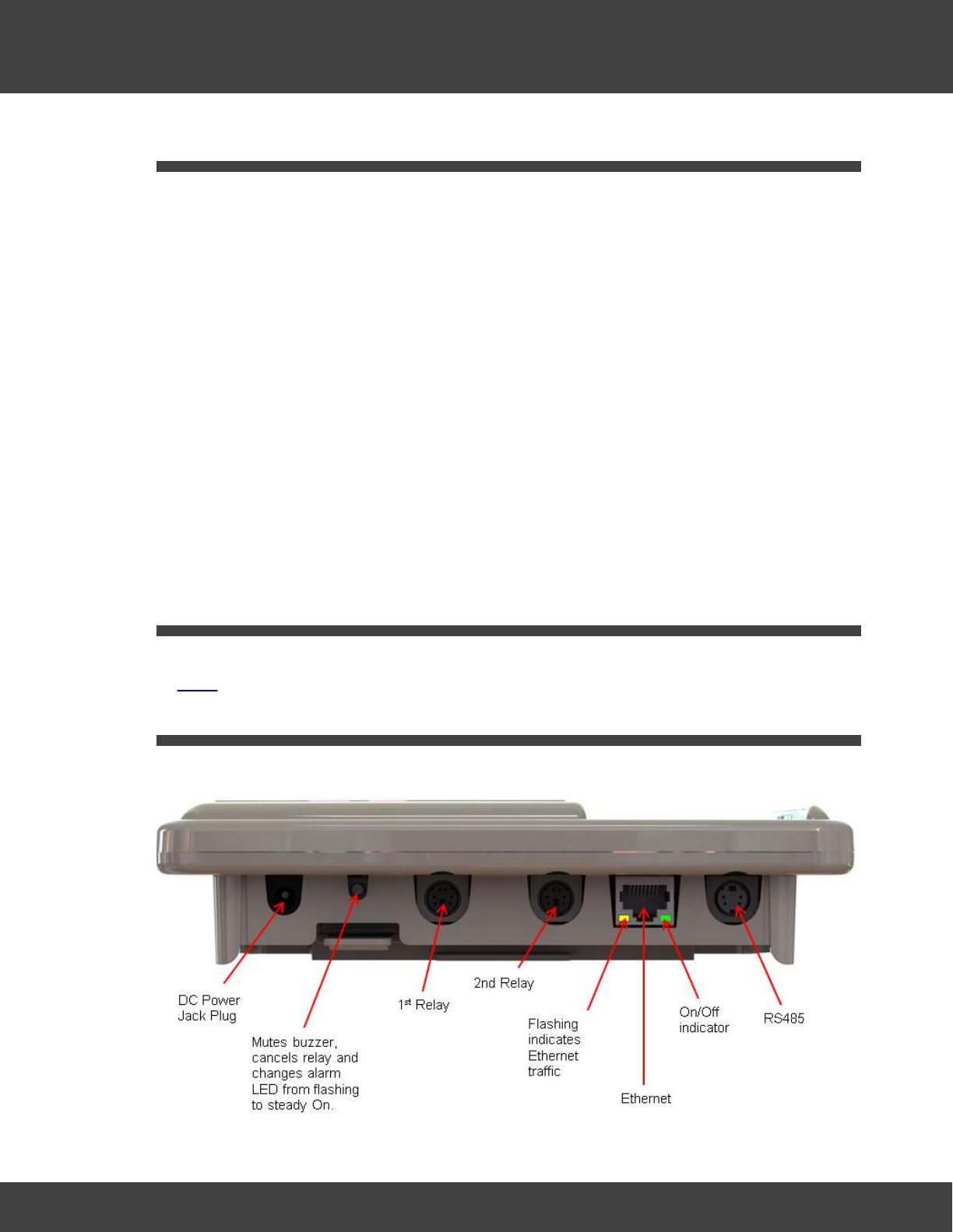
228
Notion Pro © 2017 IMC Group Ltd HP5525 Version 1.2.15
Reference Section
5.19 Manuals
The following manuals, in .pdf form, should be present on your Notion Pro install DVD:
IceSpy Notion Pro Pre-Requisites Manual
, IM5546. (You should have read this before you
purchased Notion Pro, but this manual may still be a useful source of reference).
IceSpy Notion Pro Installation Guide
, IM5529. (If you are reading this Help topic you have
already installed Notion Pro, but this manual may still be a useful source of reference).
IceSpy Notion Pro System Manual
, IM5521 (Describes the software GUI from a 'reference'
point of view, and goes through all the options in detail. Also gives a summary description of
the Notion Pro hardware.)
IceSpy Notion Pro Archive Backup Manual
, IM5549. (Describes how to back up and restore
old Notion Pro data.)
IceSpy Notion Pro Archive BaseUtil Manual
, IM5575. (Initial configuration of Notion Pro
devices. System Administrators only.)
5.20 Permissions
Permissions are System Access rights such as Edit, Delete etc. Permissions can be allocated
to Roles.
5.21 Receiver Connectors
The connectors on the underside of the Network Receiver unit are as shown below.
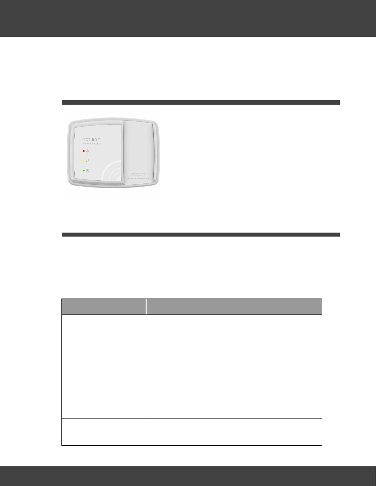
229
Notion Pro © 2017 IMC Group Ltd HP5525 Version 1.2.15
Reference Section
(The connectors on the underside of the other members of the Notion Pro Base Unit family
are similar, but some of the connectors are blanked off.)
5.22 Receiver Lights
Red (flashing)
Alarm. (For example, Temperature is outside
thresholds.)
Yellow (constant)
Receiver is connected your Network. A flashing
yellow light means that a connection has not
yet been established.
Green (constant)
Unit is powered up. Flashes to indicate radio
reception.
5.23 Roles
Users assigned to a Role inherit the Permissions assigned to the Role.
Suggested Role Definitions
The following table gives suggested roles and the settings for those roles. You may wish to
define roles and permissions slightly differently for your Site.
Role
Permissions
General Administrator
Select Ignore for:
·Access Control
·Access Logs
·Access Sites
·Activate privileged Access
·Disable User
·User Group Management
·User Management
Select the Allow option buttons for all other permissions.
Advanced User
Select Ignore for:
·Access Control
230
Notion Pro © 2017 IMC Group Ltd HP5525 Version 1.2.15
Reference Section
Role
Permissions
·Access Logs
·Access Sites
·Activate privileged Access
·Change Alarm Settings on Reset
·Device Configuration
·Disable User
·User Group Management
·User Management
Select the Allow option buttons for all other permissions.
Standard User
Select Ignore for:
·Access Reports
·Access Reports – Sensor Groups
·Access Settings
·Acknowledge Alarms
·Bulk Acknowledge Alarms
·Live View
·Live View – Sensor Groups
·Plan View
Select the Deny option buttons for all other permissions.
Guest User
Select Ignore for:
·Live View
·Live View – Sensor Groups
·Plan View
Select the Deny option buttons for all other permissions.
5.24 Specifying Alert Settings - Before you Start
You should have details of values and settings for the following items. These details should
be completed in the IceSpy Notion Pre-Requisites document, IMC doc. no. IM5546:
·SMTP Mail Server name
·Sender Email Address
·SMTP Username
·SMTP Password

231
Notion Pro © 2017 IMC Group Ltd HP5525 Version 1.2.15
Reference Section
·BCC Email Address
·Heartbeat Enable setting
·Email Alert Heartbeat Time setting
·Email Receiving Protocol (optional)
·Receive Email over SSL setting (optional)
·IMAP/POP3 Mail Server Name (optional)
·IMAP/POP3 User Name (optional)
·IMAP/POP3 User Password (optional)
5.25 User Groups
User Groups allow viewing Privileges to be set for the Group. Users added to that Group
inherit the viewing Privileges associated with that group. Any previous viewing Privileges
assigned to an individual user will be overridden by the viewing Privileges associated with that
group
5.26 User Privileges
Privileges are the viewing rights that allow a User to see Sites and Zones. Through
Privileges a user can be restricted to the number of Zones they can see. This is especially
useful on very large systems..
5.27 Compliance
The Notion Pro equipment conforms to the following international standards:
·Country specific radio approval.
·CE approval. All Notion Pro hardware carries the mark to indicate that the equipment
meets the requirements of the applicable EC directives.
·WEEE compliance.
·RoHS compliance.
·Conflict minerals.
·Reach.
See also:
R & TTE Declaration of Conformity

232
Notion Pro © 2017 IMC Group Ltd HP5525 Version 1.2.15
Reference Section
5.28 Terms and Conditions of Sale
1. GENERAL
In these Terms and Conditions 'The Company' means The IMC Group Ltd and 'The
Customer' means the person, firm or company named in this Quotation, Order
Acknowledgment, Advice Note or Invoice. No variation to these conditions shall be binding
unless agreed in writing between the authorised representatives of The Customer and the
Company. Any advice or recommendation given by the Company or its employees or
agents to The Customer or its employees or agents which is not confirmed in writing by the
Company is followed or acted upon entirely at The Customer's own risk.
2. CONTRACT
A contract shall be affected when The Company sends its confirmation and acceptance in
writing of The Customer's order. Quotations which are valid for 30 days are not binding until
the date of such acceptance. No oral quotations will be binding on The Company. Delivery
periods shall run from the date of such acceptance.
3. PRICES
Unless otherwise expressly stated the prices quoted do not include VAT or packaging,
insurance, carriage and delivery charges. Quotations represent no obligation until The
Company accepts The Customer’s order. All orders are accepted for execution at prices
current at date of despatch.
4. PAYMENT
Terms of payment are strictly net cash with order unless a credit account has been
established. Payment by an accepted credit card may be made. Where a credit account
has been established payment is strictly net monthly and payment should be made to the
Company's offices at Pendle House, Jubilee Road, Letchworth, SG6 1SP by the last day of
the month following that in which the goods are despatched. All outstanding balances not
paid on that date will be liable to compound interest charged at the rate of 1.75% per
month.
5. PROPERTY AND RISK
Property in the goods shall not pass to The Customer until The Company has been paid the
whole of the purchase price. Notwithstanding the above the risk in the goods shall pass to
The Customer upon delivery to the carrier at The Company's works.
6. DELIVERY
The Company will endeavour to adhere to the delivery date set out in the Quotation but
such delivery date is a business estimate only and The Company shall not in any way be
liable for delay in delivery or the consequences thereof however caused, including but not
limited to delay or interruption of work at The Company's works before or during the delivery
period any strike lockout labour dispute fire breakdown of machines force majeure or any
cause whatsoever beyond The Company's control in which case deliveries may be wholly or
partially suspended and the delivery period extended by the length of time during which

233
Notion Pro © 2017 IMC Group Ltd HP5525 Version 1.2.15
Reference Section
deliveries are suspended, Where goods are ready for delivery The Company may postpone
delivery at the request of The Customer provided that The Customer pays the full price of
the goods to The Company forthwith. The Company may store the goods at its own
premises or elsewhere at The Customer's sole risk and all storage, insurance and transport
charges shall be paid by The Customer.
7. CANCELLATION FEE
No contract for goods ordered may be cancelled by The Customer. If The Company
agrees to accept a cancellation it shall be entitled to charge The Customer a cancellation fee
of up to fifty per cent (50%) of the purchase price in respect of costs and expenses
incurred and other damages without prejudice to any right to claim further costs expenses
and damages howsoever arising. The Customer is responsible for returning any such goods,
at their cost, in good condition to The Company.
8. WARRANTY
The Company guarantees the goods against defects of materials or workmanship for a
period of one year commencing on the date on which the goods are dispatched. The
Company in so far as it is able will also pass on to The Customer the benefit of all other
manufacturers' guarantees connected with the goods supplied which are not of The
Company's manufacture.
The Company's liability under this clause shall apply to defects that appear during normal
and proper operational use in accordance with any operating or service manuals supplied by
The Company. The Company shall be under no liability in respect of any defect of the
goods arising from any causes beyond the Seller's reasonable control, or to defects arising
from The Customer's faulty maintenance or handling or from alterations carried out without
The Company's prior authorisation in writing or from repairs which have not been carried out
in accordance with any operating or service manual supplied by The Company or defects
arising from normal wear and tear.The Company's liability under this clause is limited to
replacing or making good the defects in the goods.
If The Company so requests, The Customer, at the expense and risk of The Customer,
shall send the goods, or part thereof which are to be replaced or made good, to The
Company or some place nominated by The Company. Any repaired or substituted goods
may be delivered to The Customer at the risk of The Customer but The Company may if it
wishes pay the cost of carriage.
9. LIABILITY
Save as provided above The Company accepts no other liability for any other conditions or
warranties expressed or implied as to the quality or fitness of any purpose of the goods and
all such conditions and warranties are to the extent permitted by law hereby expressly
excluded to the intent that save as provided above The Company shall not have liability to
The Customer or to any third party in respect of any loss or defect in the goods supplied or
in respect of any personal injury or damage or loss of any kind directly or indirectly
attributable to faults or defects in such goods and The Customer will indemnify The
Company against any such claims. Under no circumstance will The Company be liable for
any consequential loss suffered by The Customer. In the event that The Company under

234
Notion Pro © 2017 IMC Group Ltd HP5525 Version 1.2.15
Reference Section
any liability to The Customer in respect of the goods the same shall form a separate cause
of action and shall not entitle The Customer to any setting off and the full amount of all
sums payable to The Company from The Customer hereunder shall remain due and owing.
Good returned under this warranty shall be delivered to our premises at The Customers
expense and if found not to be defective (or when the defect is attributable to The
Customer’s design or materials) will be returned to The Customer at its expense and subject
to a testing charge of 15% of the invoice price together with VAT thereon if applicable.
The goods shall not be defective unless:
i. They are not in accordance with The Customers specification where this is the agreed
specification
ii. If The Customer has no such specification or to the extent that The Customers
specification is silent as to any aspect of the design function performances tolerances quality
or characteristics of the goods do not conform to The Company’s published information or if
no such information has been published the goods to not conform to the standards which
The Company considers normal or usual for products of the kind sold at a similar price. The
Company is not in a position to ensure that The Customers specification is correct and/or
sufficient for the purposes intended by The Customer and The Customer must satisfy
himself on this point.
10. CONTRACTS FOR SERVICES
a) In the event that a contract made between The Company and The Customer shall
amount to a contract for the provision of services rather than a contract for the sale of
goods then the provisions of these Terms and Conditions shall apply with such modifications
as may be necessary, to give effect to them.
b) Where specifications are to be supplied by The Customer they must be supplied before
the contract can be entered into. Where The Customer is to supply working drawings/
components these must be delivered to The Company by the agreed date. Delay in the
supply of such drawings or components will entitle The Company to defer delivery of the
goods by a period equivalent to such delay.
c) Where any additional or changed information is submitted to The Company by The
Customer The Company reserves the right to increase prices to cover any costs (including
overheads) arising from any losses incurred by The Company as a result of such alteration
and/or to extend the delivery period.
d) Where goods have been supplied to The Customer's specifications The Company
accepts no liability for any failure or defect in such goods, and The Customer shall indemnify
The Company against all actions, claims, costs and proceedings, including claims that the
specification or goods infringe(s) the intellectual property rights of another. The Company
gives no warranty as to the fitness for any particular purpose of goods so supplied to The
Customer's own specifications and accepts no liability for clerical or stenographical errors on
the drawings or specification provided by The Customer.
e) The Company reserves the right to sub-contract the fulfillment of any order or contract
or any part thereof.

235
Notion Pro © 2017 IMC Group Ltd HP5525 Version 1.2.15
Reference Section
f) Any experimental results supplied or recommendations made under a Service contract are
given in good faith within the limitations of the data available, but no warranty, express or
implied, is given as to the performance of, or results obtained from such service and The
Company cannot accept any liability for the consequences of using or applying the said
results or recommendations.
11.
If any of these Clauses or any part of these Clauses is rendered void or unenforceable by
any legislation to which it is subject it shall be void or unenforceable to that extent but no
further.
12.
This contract shall be governed by and construed in accordance with the Laws of England.
May 2011

The Notion Pro Hardware
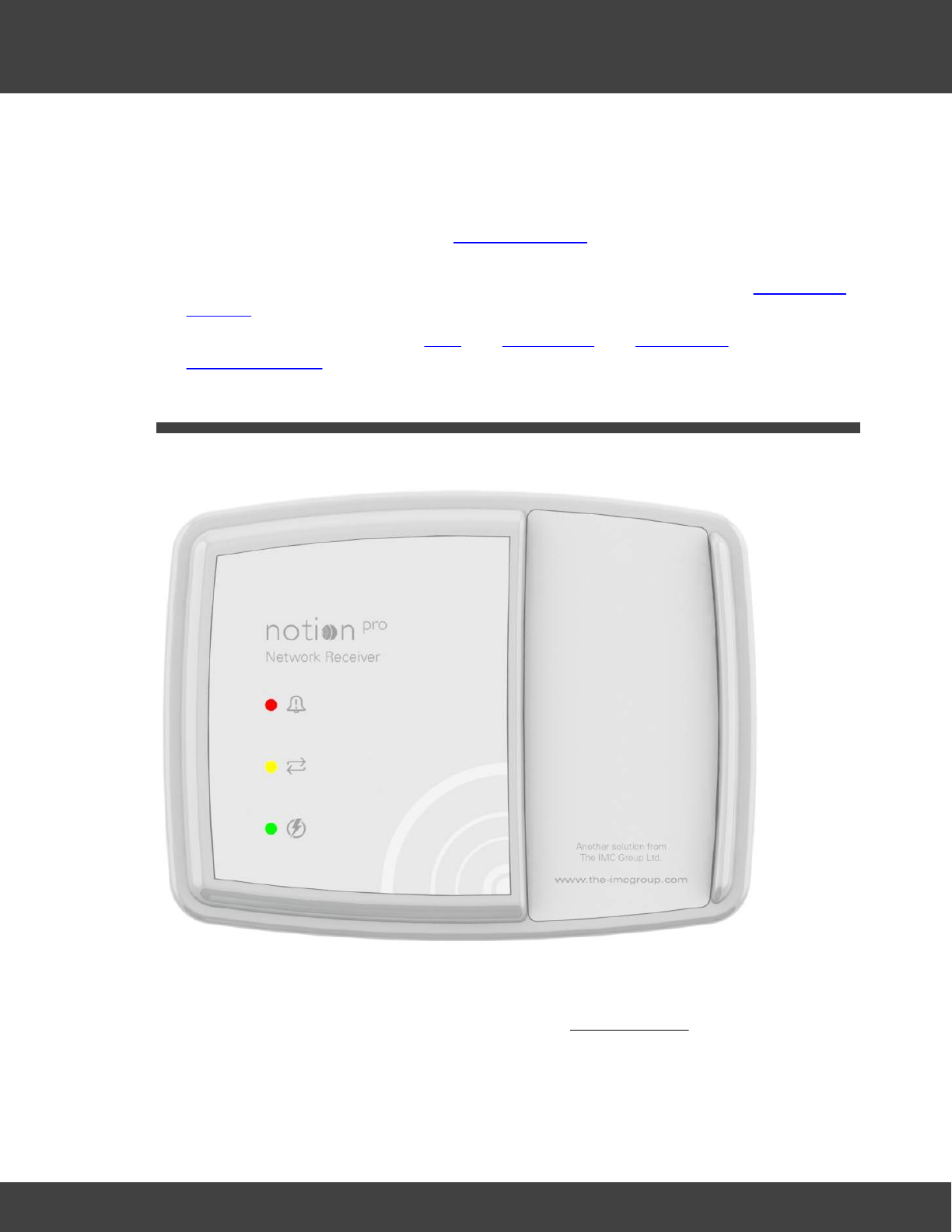
237
Notion Pro © 2017 IMC Group Ltd HP5525 Version 1.2.15
The Notion Pro Hardware
6The Notion Pro Hardware
A Notion Pro system contains the following hardware:
·Transmitters to monitor the levels of temperature and other variables and transmit the
data by radio to the Receiver. See The Transmitters for more details of the
transmitters.
·the Network Receiver (may also be referred to as the Base Unit). See the Network
Receiver.
·Optional Items. These are the Echo, the ARB Module, the SMS Module and the
Calibration Module.
6.1 The Network Receiver
The Network Receiver receives radio signals from the Notion Pro Transmitters and passes
them over a network to the Notion Pro software. The Hybrid Receiver will also receive
signals from IceSpy System 5 Scout transmitters, Notion Pro Legacy and Notion Pro
transmitters.
Key features:

238
Notion Pro © 2017 IMC Group Ltd HP5525 Version 1.2.15
The Notion Pro Hardware
·IMC Part No IN-NR001x (where x indicates the territory-specific frequency, for example
F1 for Europe, F2 for USA; this notation will be used throughout this Help). Hybrid
unit is IN-HR001-Fx.
·Wall mountable.
·Internal aerials as standard – external aerials are a factory-fitted option.
·Red LED for alarm (normal state off), green LED for power (normal state on), yellow LED
for communications (normal state on). See also LEDs.
·Mains powered from supplied adaptor.
·TCP/IP communications.
·Two on-board Relays, one configured for alarm activation - driven by Notion Pro Local
Alarms, one for communications and power failure.
·RS485 output for optional Modbus or IMC MS1000 system relay cards - driven by Notion
Pro Local Alarms.
·Memory lasts for 5 days for up to 50 sensors.
·IP53 rated.
6.1.1 LEDs
Green
(constant/
flashing)
Unit is powered up. Flashes to indicate radio reception.
Red (flashing)
Alarm. (For example, temperature is outside thresholds.) Changes to
steady red if Reset button is pressed. Goes off when Alarm Clear signal is
received.
Yellow
(constant)
Receiver is connected your Network. A flashing yellow light means that an
Ethernet connection has not yet been established.
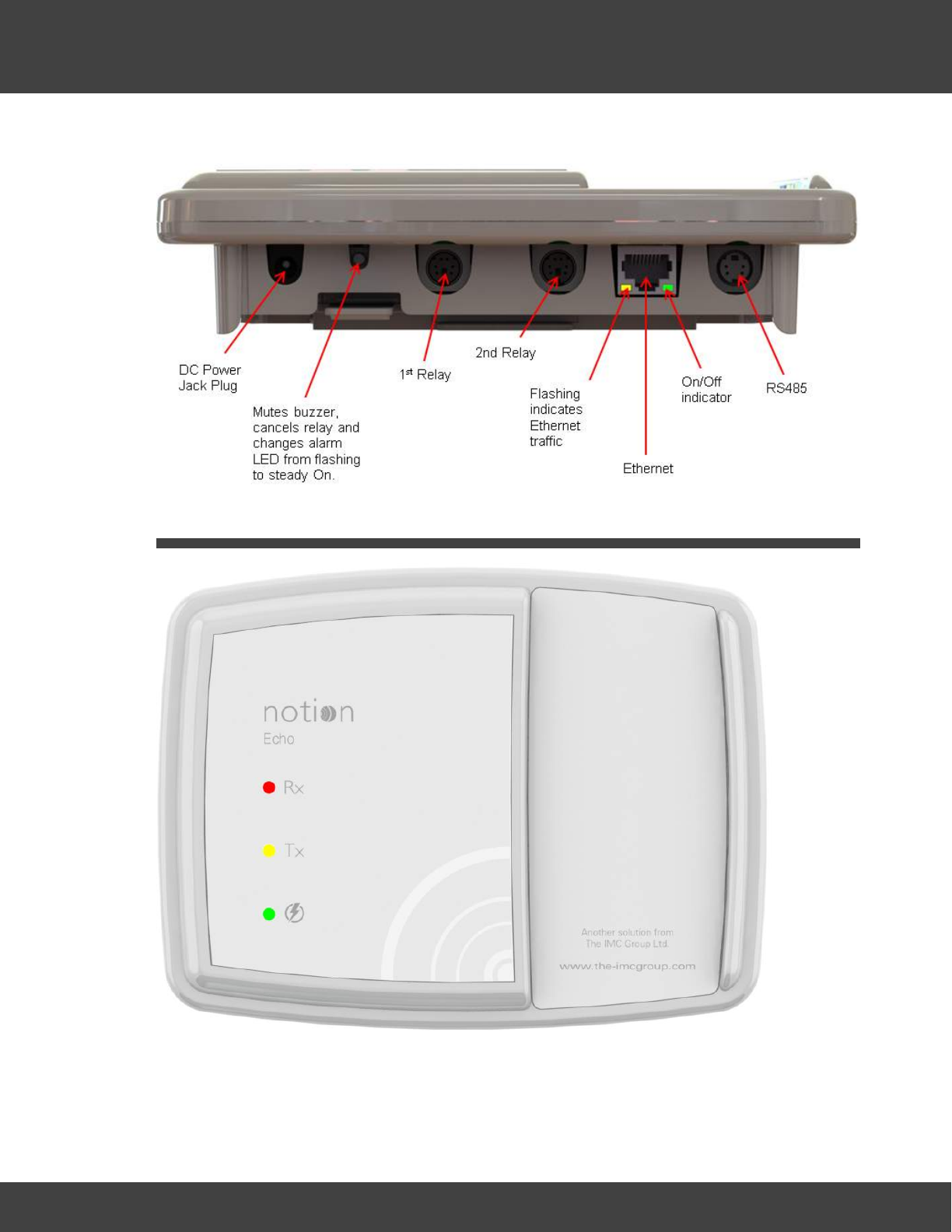
239
Notion Pro © 2017 IMC Group Ltd HP5525 Version 1.2.15
The Notion Pro Hardware
6.1.2 Connectors
6.2 The Echo Module
The Echo module provides a Repeater function for transmitted signals, should this be
required in your installation. Key features:
·IMC Part No IN-RP002F1
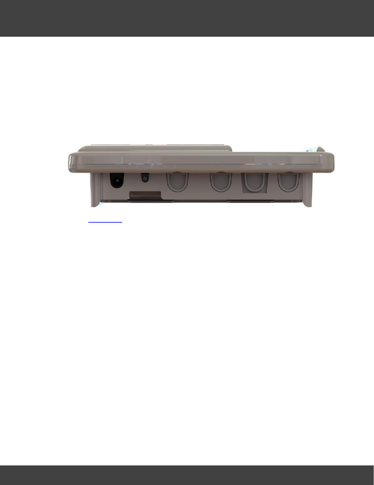
240
Notion Pro © 2017 IMC Group Ltd HP5525 Version 1.2.15
The Notion Pro Hardware
·Wall mountable.
·Green LED for power (normal state on), red LED to indicate signal being received, 1
yellow LED to indicate signal being transmitted.
·Mains powered from supplied adaptor.
·Battery backup for 3 days.
·IP53 rated.
6.2.1 Connectors
See also Connectors.
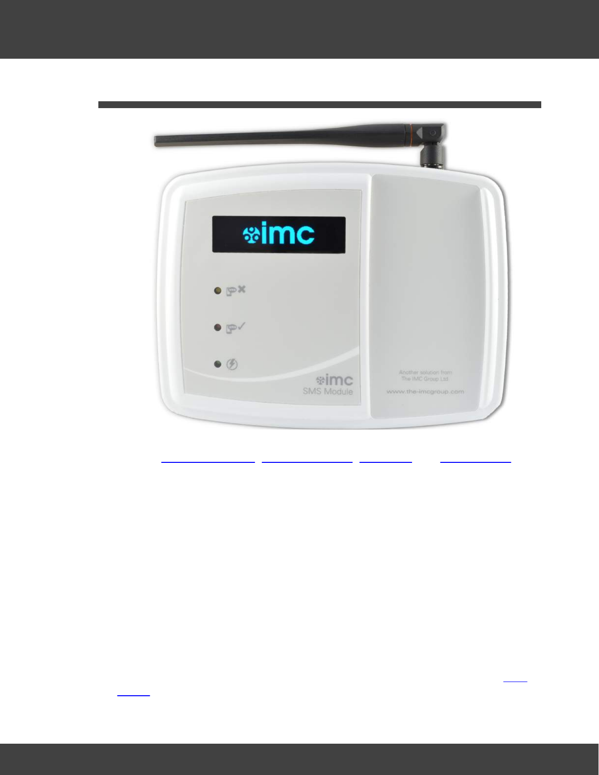
241
Notion Pro © 2017 IMC Group Ltd HP5525 Version 1.2.15
The Notion Pro Hardware
6.3 The SMS Module
This unit gives the ability for Transmitter alarms to be sent as SMS messages to mobile
phones. See SMS Global Settings, SMS System Alerts, User Alerts, and SMS heartbeat, for
details of SMS configuration. Key features:
·IMC Part No IN-TA001
·Wall-mountable.
·External aerial.
·Red LED for alarm (normal state off), green LED for power (normal state on), yellow
LED for communications (normal state on).
·OLED display showing signal strength and alarm message status.
·Base push-button – quick press shows setup and signal strength, (RSSI), 5-second
press sends SMS test message.
·Mains powered from supplied adaptor.
·TCP/IP communications.
·Two on-board Relays, one configured for alarm activation - driven by Notion Pro Local
Alarms, one for communications and power failure.
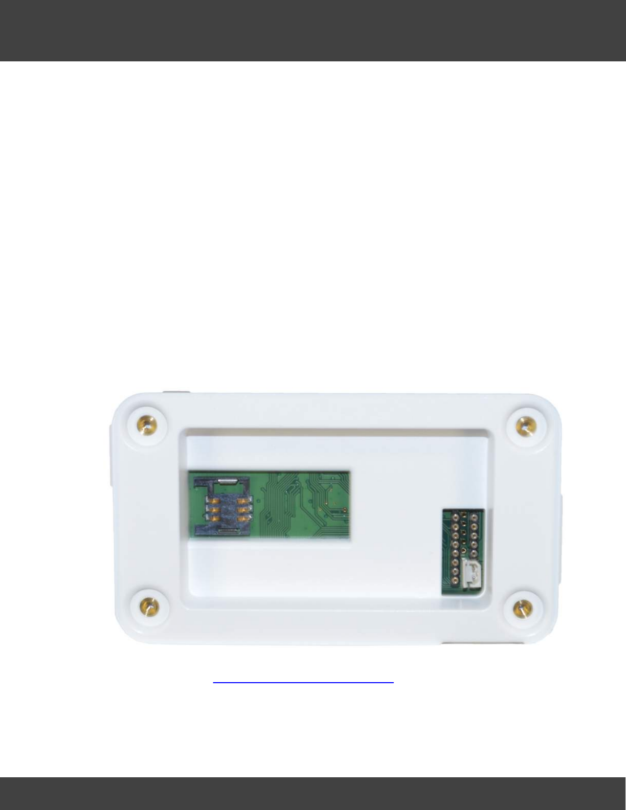
242
Notion Pro © 2017 IMC Group Ltd HP5525 Version 1.2.15
The Notion Pro Hardware
·Rechargeable battery backup, to send power fail messages.
·SIM socket – accessed from back of battery compartment.
·IP53 rated.
6.3.1 Installation and Operation
SIM Installation
Note:
Make sure that both SMS sending and receiving is enabled by your cellular Service provider,
for the SIM card you are using.
The SIM card is not hot-swappable, do NOT attempt to remove the SIM card without
removing power and the battery first.
It is recommended that the battery be removed, when the SMS Module is not in use.
The SIM card must be installed prior to battery installation and wall mounting.
Remove the battery cover and slide the SIM card into the exposed SIM socket, so that the
gold plate contacts on the SIM card connect with the gold plated contacts of the SIM
socket.
Once the SIM is correctly located in the socket, fit the battery, battery cover, and mount
the SMS module; see Installing your Notion Pro Equipment for details.
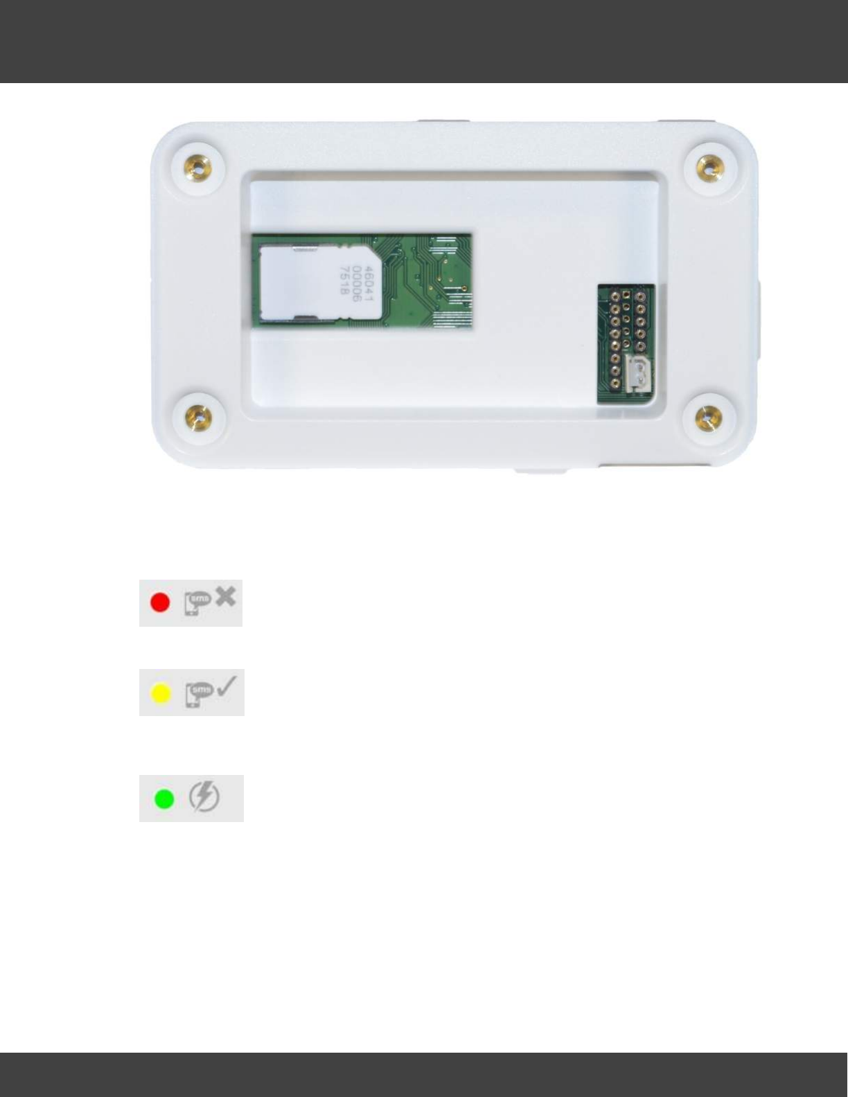
243
Notion Pro © 2017 IMC Group Ltd HP5525 Version 1.2.15
The Notion Pro Hardware
LED Operation
The SMS Module has three LED's which provide a quick visual indication of current status.
The red SMS Cross LED will be off during normal operation; it will flash slowly
during a power fail.
The amber SMS tick LED will be on during normal operation; it will flash
approximately twice a second if there is no network connection to the Notion
pro server.
The green power LED will illuminate during normal operation; it will go off
during a power fail condition.
Push Button
Briefly press the push button to display SIM status and signal strength, (RSSI).
When the relay is on due to an Alarm, a brief press of the push button will reset the alarm
relay.
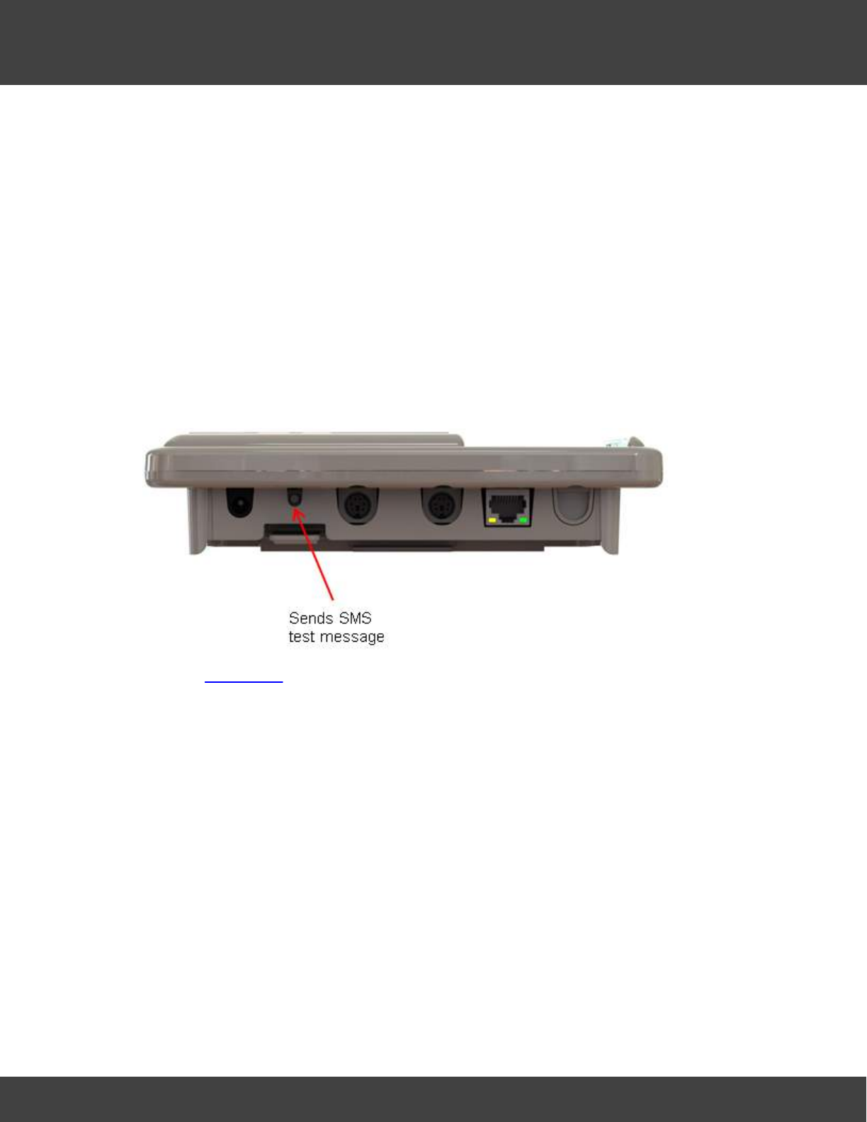
244
Notion Pro © 2017 IMC Group Ltd HP5525 Version 1.2.15
The Notion Pro Hardware
Press and hold the push button for at least five seconds to send a test message to one of
the SMS Power & Comm's Group phone numbers. The SMS Module will display the phone
number at the bottom of the OLED display, when the message is sent.
Error Message
When initially powered on pressing the push button will display "Unit not fully powered up.
Wait 60 seconds and try again."; if pressing the button continues to display the same
message after a few minutes, then there may be a problem with your SIM or cellular
account.
6.3.2 Connectors
See also Connectors.
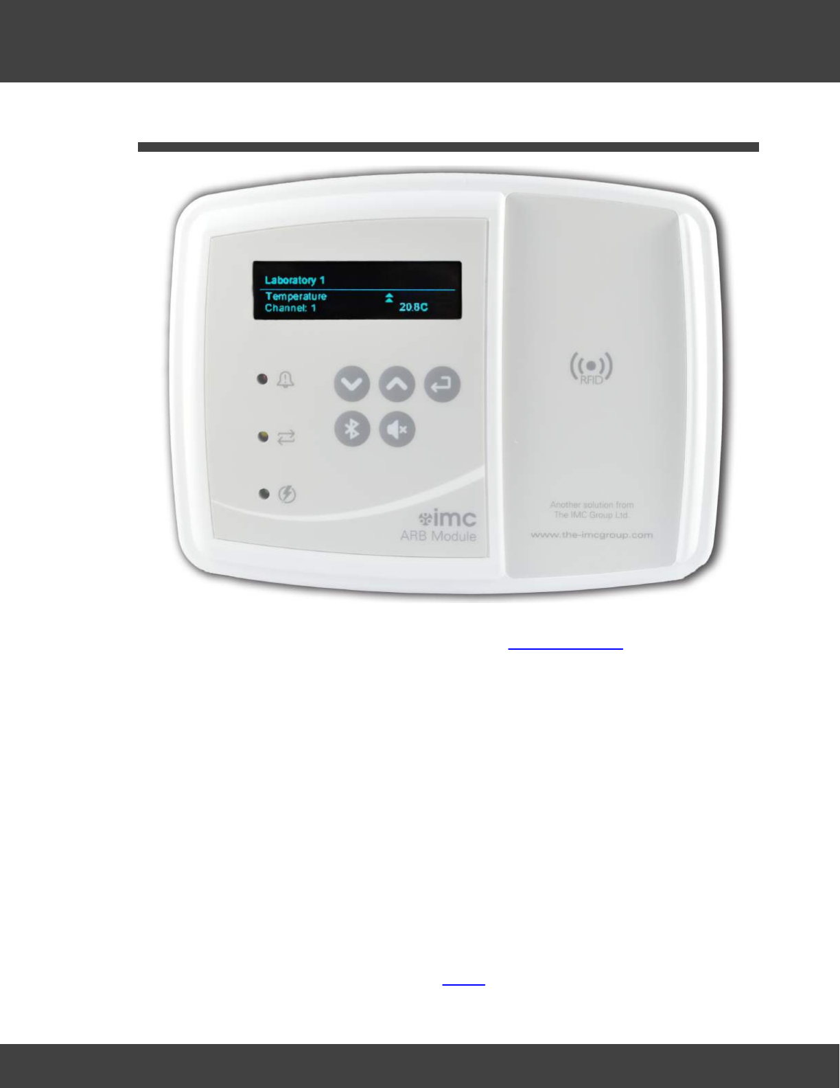
245
Notion Pro © 2017 IMC Group Ltd HP5525 Version 1.2.15
The Notion Pro Hardware
6.4 The ARB Module
The ARB unit gives an alarm display, with a keypad enabling the user to cycle through alarm
information. Has RFID and Bluetooth connectivity. See ARB Module Help
·IMC Part No IN-NA002.
·Wall mountable.
·Bluetooth module to interface to MM2000 series recording thermometer.
·Red LED for alarms (normal state off), green LED for power (normal state on), 1 yellow
LED for network status (normal state on).
·Mains powered from supplied adaptor.
·TCP/IP communications.
·On-board alarm relay - driven by Notion pro Local Alarms - and reset button.
·RS485 output to drive IMC MS1000 system relay cards - driven by Notion Pro Local
Alarms.
·ARB units to be able to communicate with each other via the PC software for relay
activation.
·RFID interface and cradle for transmitter backfill.
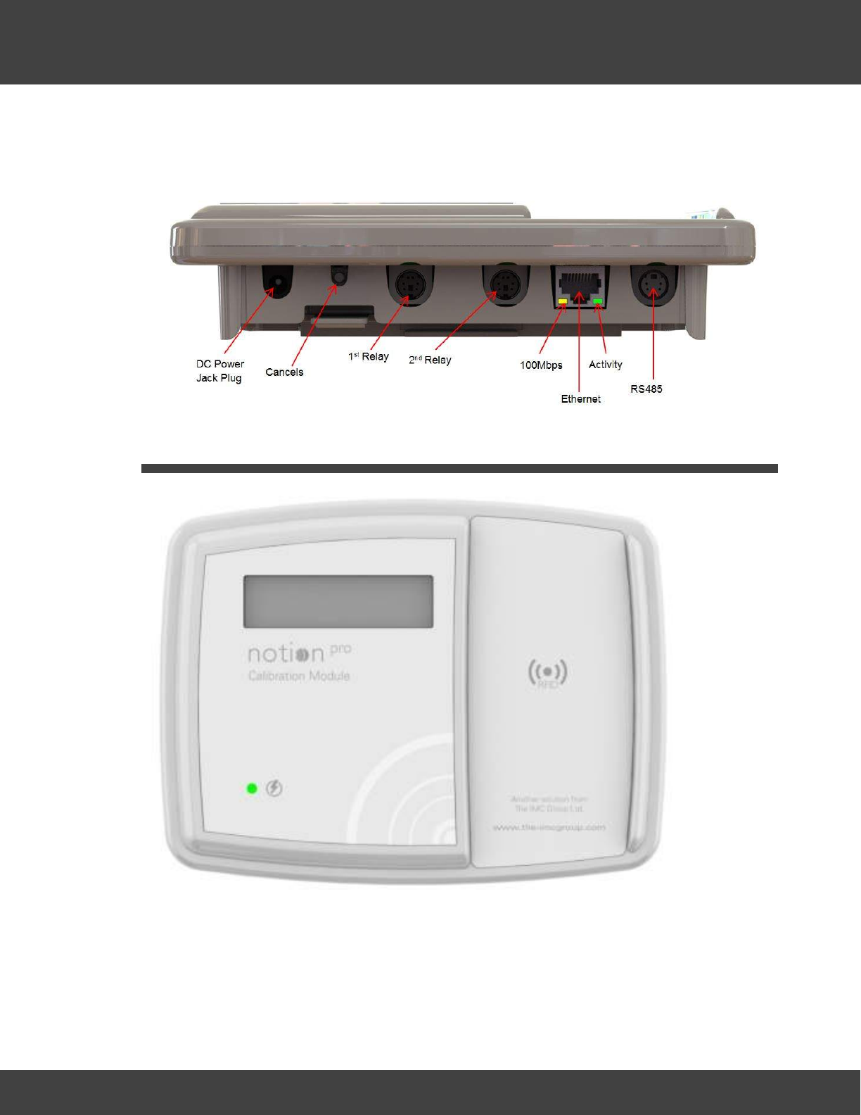
246
Notion Pro © 2017 IMC Group Ltd HP5525 Version 1.2.15
The Notion Pro Hardware
·IP53 rated.
6.4.1 Connectors
6.5 The Calibration Module
The Calibration Module collects data from the Notion Pro Calibration Tool (part of the Notion
Pro software) and transfers the data to transmitters via RFID. Transmitter to be placed on
Calibration Module cradle. Built in licence key routine to communicate with Server. Licence to
use device will expire annually.
·IMC Part No IN-CM01.
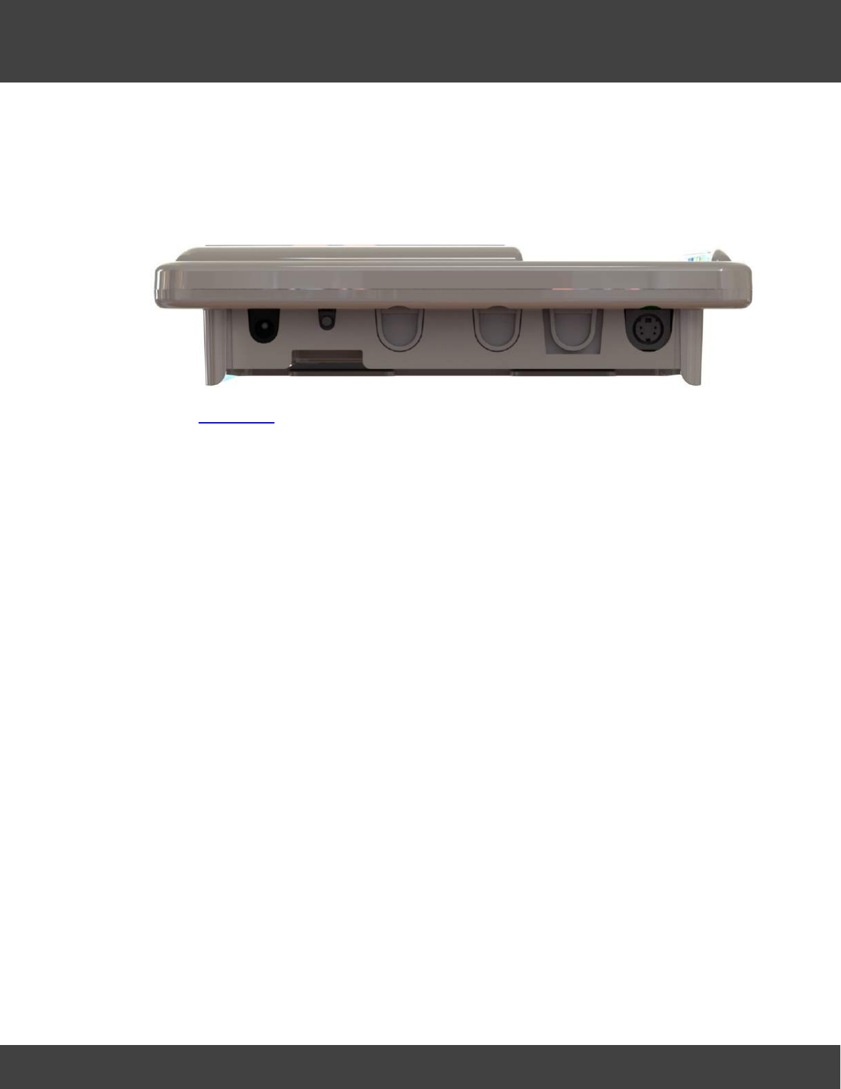
247
Notion Pro © 2017 IMC Group Ltd HP5525 Version 1.2.15
The Notion Pro Hardware
·Green LED for power (normal state on).
·Mains powered from supplied adaptor..
·IP53 rated.
6.5.1 Connectors
See also Connectors.
6.5.2 Display
Alarm display. Used to show failed communications.
6.5.3 Operation
Would usually be held by a Calibration Engineer, who would come in to the customer’s
premises on request. Would be used flat on a table connected by RS485 cable to the
Engineer’s laptop.
The Calibration Tool interacts with the Calibration Module and acts as a virtual display and
keyboard. When a transmitter is to be calibrated it must be placed on the Calibration
Module cradle. The Engineer then puts the Calibration Module into calibration mode via the
calibration tool software.
When a Transmitter is put into calibration mode it sends messages to the System to identify
that it is in calibration mode to stop alarms. When the transmitter is taken out of calibration
mode another message is sent to the System that it is back in normal mode. If the sensor
for some reason has not been taken out of calibration mode in 6 hours then an alarm is
sent to warn that the transmitter is still in calibration mode.
Once the unit has gone through its calibration routine the Engineer will take it out of
calibration mode. All calibration details will be held in the Transmitter itself, so no
adjustments to the Notion Pro data base are required.
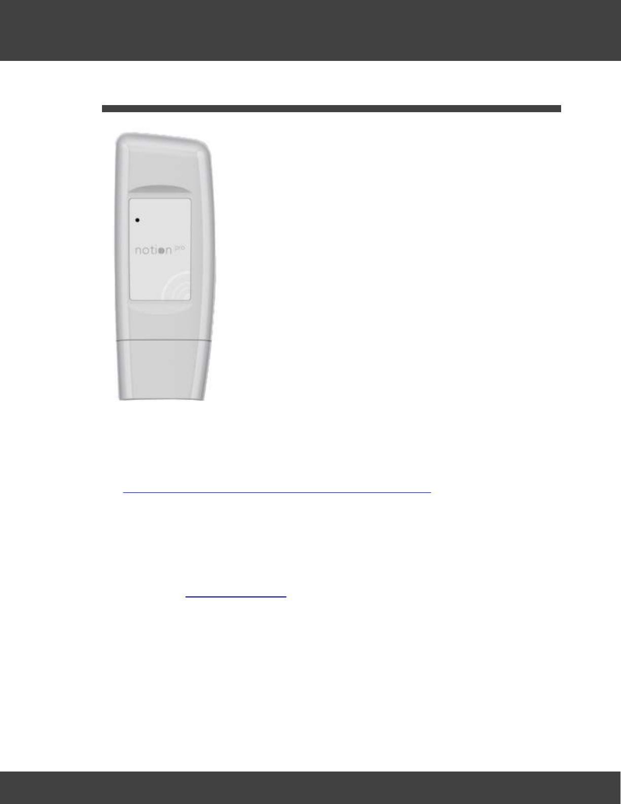
248
Notion Pro © 2017 IMC Group Ltd HP5525 Version 1.2.15
The Notion Pro Hardware
6.6 The Transmitters
All the members of the Notion Pro Transmitter family have the same basic enclosure (see
above) and share many common characteristics. The available sensors can monitor
temperature and relative humidity, voltage and 4-20mA current, (intended to interface with
third party sensors), as well as providing door alarms. There are also external PT100 and
thermocouple sensor probe options. For more detail on the Notion Pro transmitter family,
see http://www.the-imcgroup.com/notionpro/temperature-sensors.
All transmitters can be wall-mounted or free standing, as required. As far as possible, the
Transmitter units should be placed where they will not be subject to electromagnetic
interference and where they will not be shielded by walls, doors, metal furniture, appliances
etc. Note that if you have more than one Network Receiver on your Site and the signal
from a given transmitter is being picked up by more than one Receiver, you can associate
the transmitter with the Receiver unit which is showing the highest signal strength for that
transmitter. See Device Configuration.
·All units can operate within a -30°C to +50°C temperature range.
·All units have user-replaceable 1.5V Lithium AA batteries. These have an expected life
of over 2years and work over -30°C to +50°C temperature range. 1.5V AA alkaline can
be used but with a reduced battery life and a reduced operating temperature range (0°
C to +40°C).
LED Operation
The transmitter LED indicates when the unit is transmitting data, and will briefly flash
approximately once every minute.
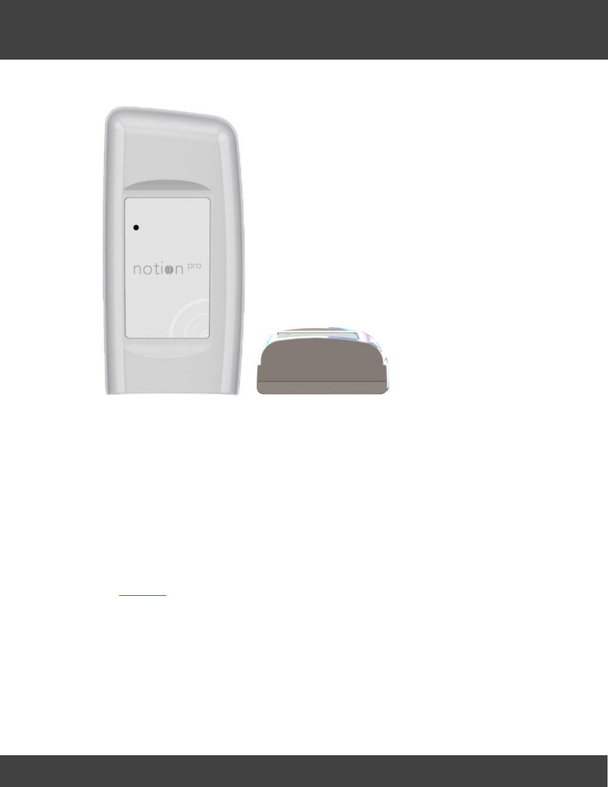
249
Notion Pro © 2017 IMC Group Ltd HP5525 Version 1.2.15
The Notion Pro Hardware
6.6.1 Single Channel, Air Temperature, Internal
·IMC Product Code IN-TH001Fx
·Product Family: NP3000 series
·Accuracy ±0.5°C, 0.1°C resolution.
·Transmits data once per minute
·Battery level status and alarms.
·Calibration options are return to IMC, or on site by trained Engineer.
·Gap filling protocol via ARB Module with RFID interface.
·Green Status LED for commissioning and fault finding.
·IP65 rated.
·Approvals.
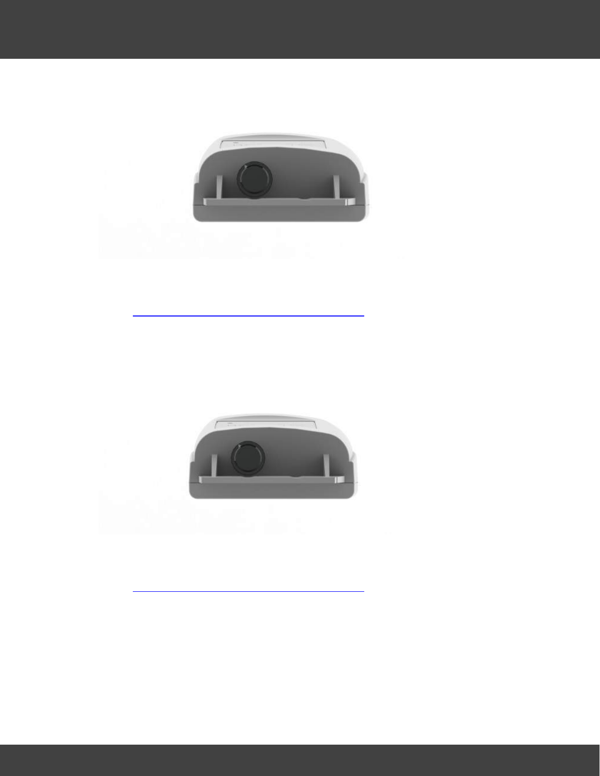
250
Notion Pro © 2017 IMC Group Ltd HP5525 Version 1.2.15
The Notion Pro Hardware
6.6.2 Single Channel, Air Temperature, Internal + Door Switch
·IMC Product Code IN-THD01Fx
·Product Family: NP3000 series
·As Single Channel Internal Thermistor Temperature but with door monitoring and alarm
function.
·External sensor range -30°C to +50°C.
6.6.3 Single Channel, External Temperature Probe
·IMC Product Code IN-TH002Fx
·Product Family: NP3000 series
·As Single Channel Internal Thermistor Temperature but replacing the internal sensor with
an external sensor via a waterproof connector.
·External sensor range -40°C to +70°C.
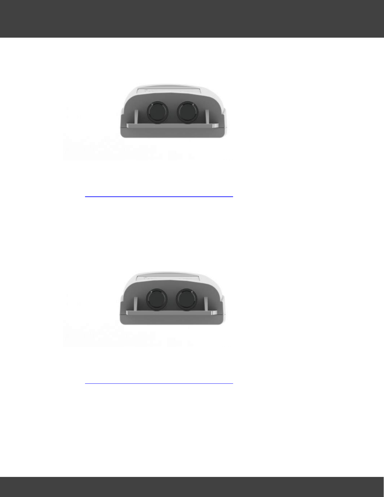
251
Notion Pro © 2017 IMC Group Ltd HP5525 Version 1.2.15
The Notion Pro Hardware
6.6.4 Single Channel, External Temperature Probe + Door Switch
·IMC Product Code IN-THD02Fx
·Product Family: NP3000 series
·As Single Channel Internal Thermistor Temperature but replacing the internal sensor with
an external sensor via a waterproof connector.
·External sensor range -40°C to +70°C
·Dual Channel Internal and External.
6.6.5 Dual Channel Internal/External Temperature Probe
·IMC Product Code IN-TH003Fx
·Product Family: NP3000 series
·As Single Channel Internal Thermistor Temperature with the addition of external sensor
channel via waterproof connector.
·External sensor range -40° to +70°C
·No door monitoring and alarm function.
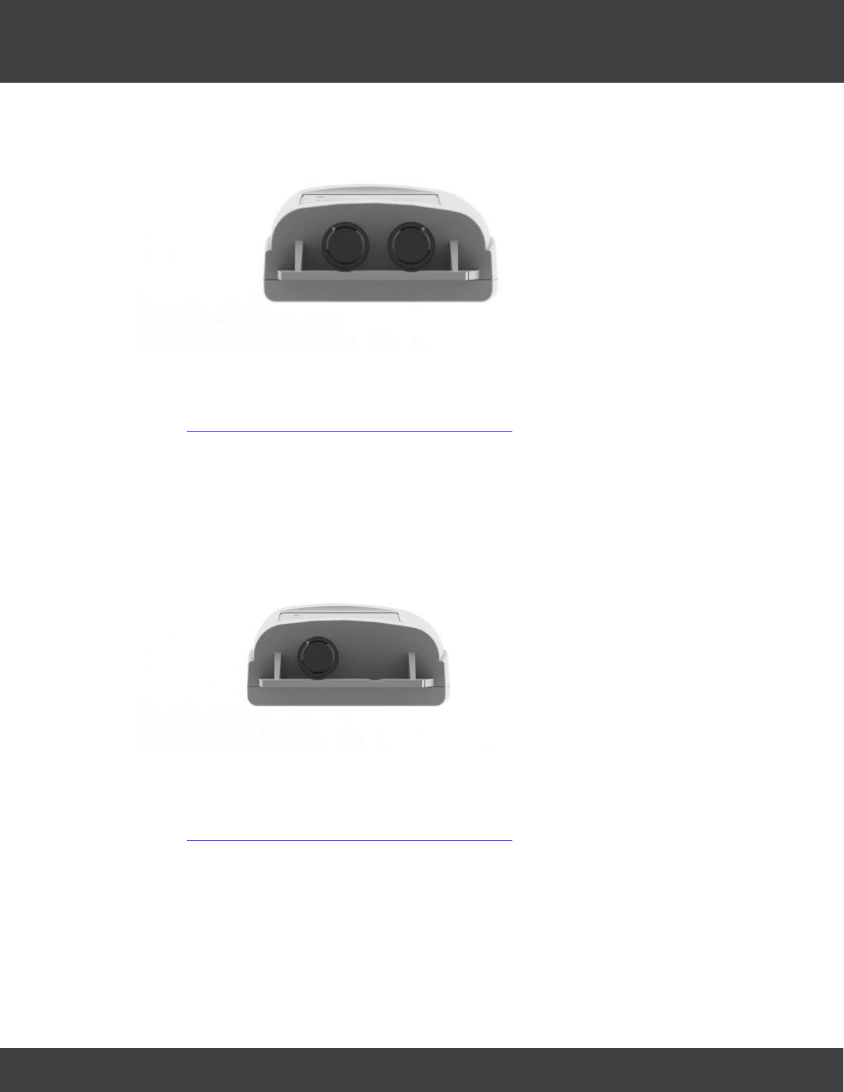
252
Notion Pro © 2017 IMC Group Ltd HP5525 Version 1.2.15
The Notion Pro Hardware
6.6.6 Dual Channel External Thermistor
·IMC Product Code IN-TH004Fx
·Product Family: NP3000 series
·As Single Channel Internal Thermistor Temperature with the addition of a second
external sensor channel.
·Sensor range -40° to +70°C.
6.6.7 Single Channel, External PT100 Probe
·IMC Product Code IN-PT001Fx
·Product Family: NP3100 series
·As Single Channel Internal Thermistor Temperature with the internal thermistor being
replaced by a single external 4-wire Class A PT100 probe. Used to measure
temperature at a specific point, typically inside a freezer. This unit can withstand a much
wider temperature range that an internal thermistor.
·Range -100°C to +200°C.
·Resolution 0.1°C.
·Accuracy ± 0.1°C calibrated.
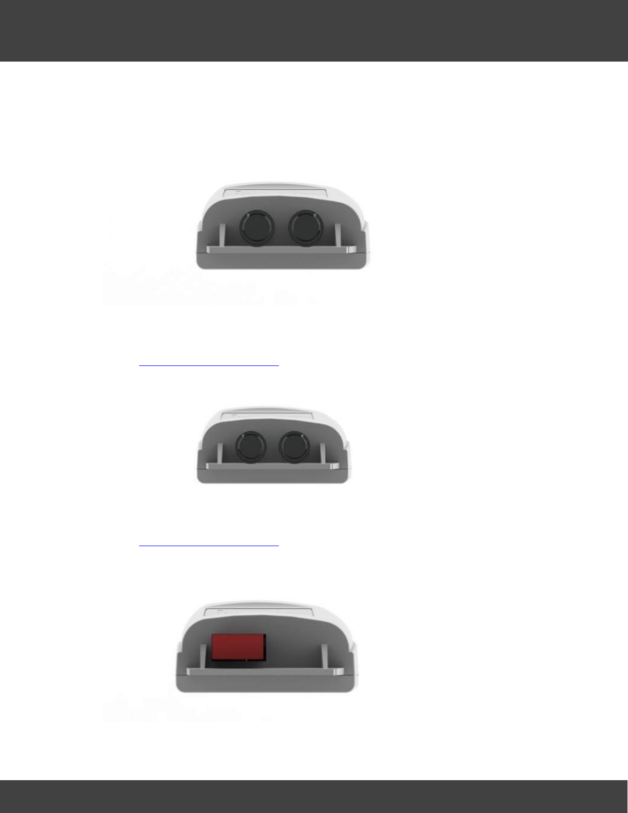
253
Notion Pro © 2017 IMC Group Ltd HP5525 Version 1.2.15
The Notion Pro Hardware
·PT100 Probe Class A accuracy un-calibrated.
·Probe connected via a waterproof connector.
6.6.8 Single Channel PT100 Probe + Door Switch
·IMC Product Code IN-PTD01Fx
·Product Family: NP3100 series
·As Single Channel PT100 Probe with door monitoring and alarm function.
6.6.9 Dual Channel PT100 Probe
·IMC Product Code IN-PT002Fx
·Product Family: NP3100 series
·As Single Channel PT100 Probe with the addition of a second external PT100 channel.
6.6.10 Single Channel Type T Thermocouple
·IMC Product Code IN-TT001Fx
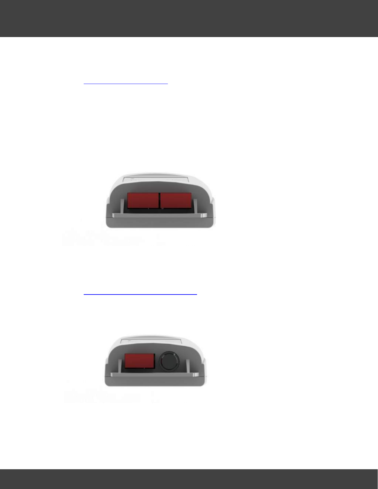
254
Notion Pro © 2017 IMC Group Ltd HP5525 Version 1.2.15
The Notion Pro Hardware
·Product Family: NP3200 series
·Single thermocouple base connector
·As Single Channel PT100 Probe with the internal thermistor being replaced by a single
Type T thermocouple.
·Range -200°C to +350°C
·Resolution 0.3°C
·Accuracy ± 0.5°C.
·IP53
6.6.11 Dual Channel Type T Thermocouple
·IMC Product Code: IN-TT002Fx
·Product Family: NP3200 series
·Dual thermocouple base connector
·As Single Channel Type T Thermocouple with the addition of a second external Type T
thermocouple channel.
6.6.12 Single Channel Type T Thermocouple + Door Switch
·IMC Product Code: IN-TTD01Fx
·Product Family: NP3200 series
·Single thermocouple base connector
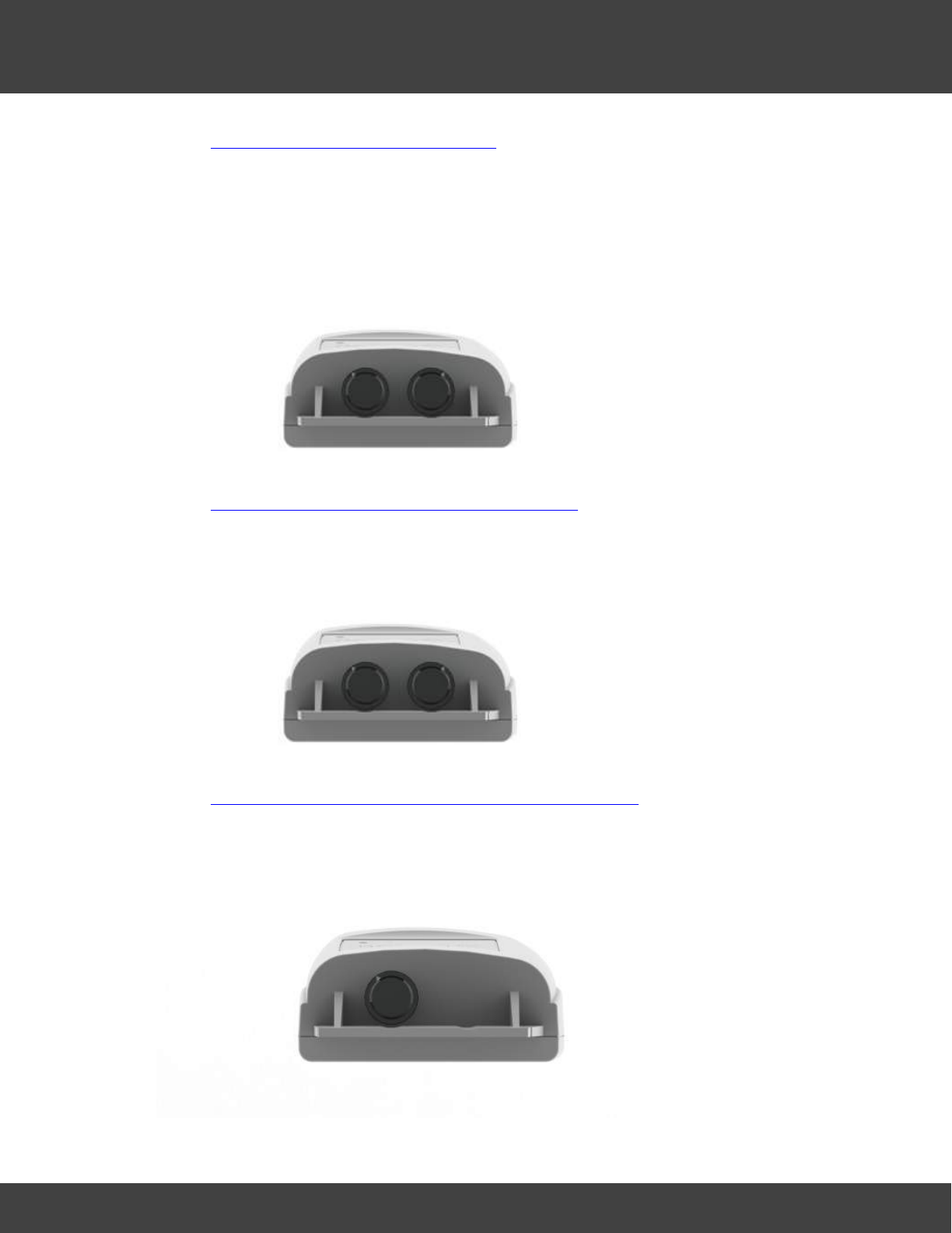
255
Notion Pro © 2017 IMC Group Ltd HP5525 Version 1.2.15
The Notion Pro Hardware
·As Single Channel Type T Thermocouple with door monitoring and alarm function.
·Range -200°C to +350°C
·Resolution 0.3°C
·Accuracy ± 0.5°C.
·IP53
6.6.13 Dual Channel 4-20mA Input
·IMC Product Code IN-MA001Fx
·As Single Channel Internal Thermistor Temperature with the internal thermistor being
replaced with two current channels.
·Input 4-20mA.
6.6.14 Dual Channel Voltage Input Transmitter
·IMC Product Codes IN-VT001Fx, IN-VT002Fx, IN-VT003Fx
·As Single Channel, Air Temperature, Internal + Door Switch the internal thermistor being
replaced with two voltage channels.
6.6.15 Temperature and RH Transmitter
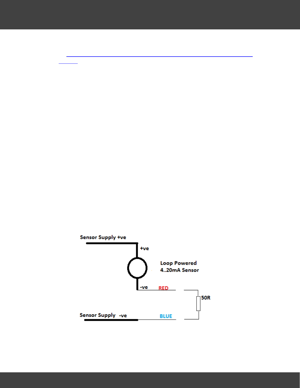
256
Notion Pro © 2017 IMC Group Ltd HP5525 Version 1.2.15
The Notion Pro Hardware
·IMC Product Code IN-RH001Fx
·As Single Channel Internal Thermistor Temperature + door monitoring and alarm
function using the internal thermistor.
·Sensor type: Sensirion type SHT75.
·RH range 10-90%.
·Resolution 0.1%.
·Accuracy ±3%.
·Sensor mounted in external housing fixed to case.
6.6.16 Linear Transmitter (1V 5V 10V 4 to 20mA)
Hardware
Connect the supplied cable as follows: Red +ve, Blue -ve
The input impedance of the 0...10V and 0...5V voltage units is a nominal 10k, that of the
0...1V device is 100k. They can withstand a permanent over voltage of 2 * nominal, and
short term polarity reversal.
0...20mA devices present an internal load resistance of 50R and will normally be connected
as shown below. The user must ensure that no more than 2V is applied across the Red and
Blue Notion Pro connections under any circumstances. The 50R resistance shown is internal
to the device; the user does NOT need to add this.
4-20mA Loop Powered Sensor Connection
With a gain of 1.0 and offset = 0 (default) the software will read V or mA directly. To read
in other engineering units set the OFFSET to be the voltage/current at which the device
reads 0 and the gain/units as required.
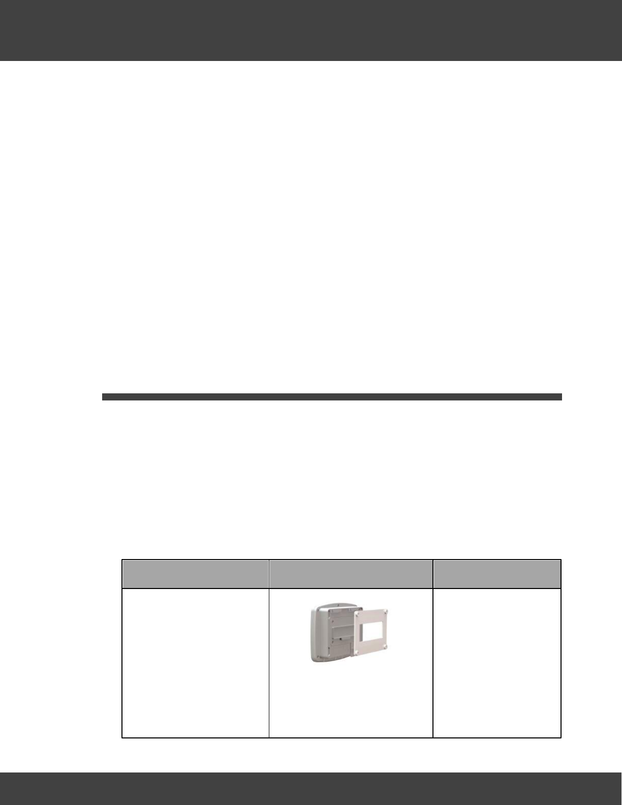
257
Notion Pro © 2017 IMC Group Ltd HP5525 Version 1.2.15
The Notion Pro Hardware
Example 1 - A 0...1V sensor corresponds to +/-100Bar
Offset =0.500, Gain=100/0.5=200, Units=’BAR’
For 4 to 20mA: Gain = sensor range / 16, Offset = 4 - (minimum sensor reading / Gain)
Example 2 - A 4...20mA sensor corresponds to 0 to 100Bar
Offset =4.00, Gain=100/16=6.25, Units=’BAR’
Example 3 - A 4...20mA sensor corresponds to 90 to 100Bar
Gain = (100 – 90) / 16 = 0.625, Offset = 4 - (90 / 0.625) = -140, Units=’BAR’
Note: Applying signals levels over the limits stated above may damage the unit
and will invalidate the warranty
6.7 Base Unit Installation Procedure (typical)
Note:This procedure takes you through the generic setup steps for physically setting up
the members of the Notion Pro Base Unit family, that is:
·Network Receiver
·Echo Module
·SMS Module
·ARB Module
Each of these units will be referred to as a ‘Base Unit’ in the following procedure.
Install Step
Notes
1. Using the mounting
bracket as a drilling
template, drill holes for
the Base Unit wall
mounting bracket into
the wall at an
appropriate location.
2. Using the spacers
provided to give
When mounting the
Base Unit, you should
bear in mind that you
may need to run cables
from the Base Unit to
the 12V power supply,
also Ethernet and
RS485 connections.
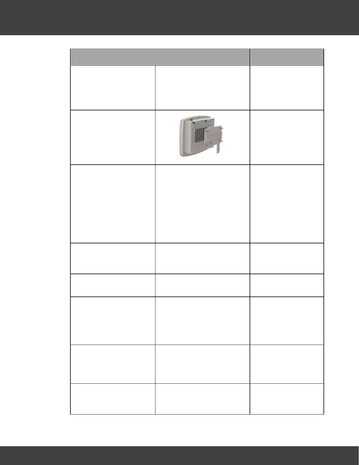
258
Notion Pro © 2017 IMC Group Ltd HP5525 Version 1.2.15
The Notion Pro Hardware
Install Step
Notes
clearance, Screw the
mounting bracket to
the wall.
3. Using a Phillips
screwdriver, remove
and retain the screws
from the battery cover
plate at the rear of the
Base Unit.
4. Insert the backup
battery into the recess
at the rear of the Base
Unit, taking care to
insert the connector
attached to the battery
into the matching
connector within the
Base Unit.
5. Screw the battery
cover plate to the rear
of the Base Unit.
6. Attach the Base Unit to
the mounting bracket.
7. Using the supplied RJ45
cable, connect the
Base Unit to your
Network.
(Echo Module
communicates by radio
and must NOT be
connected to a
Network.)
8. Using the supplied
cable, connect the
Base Unit to its 12V
power supply.
9. Plug the power supply
cable into the power
supply unit.
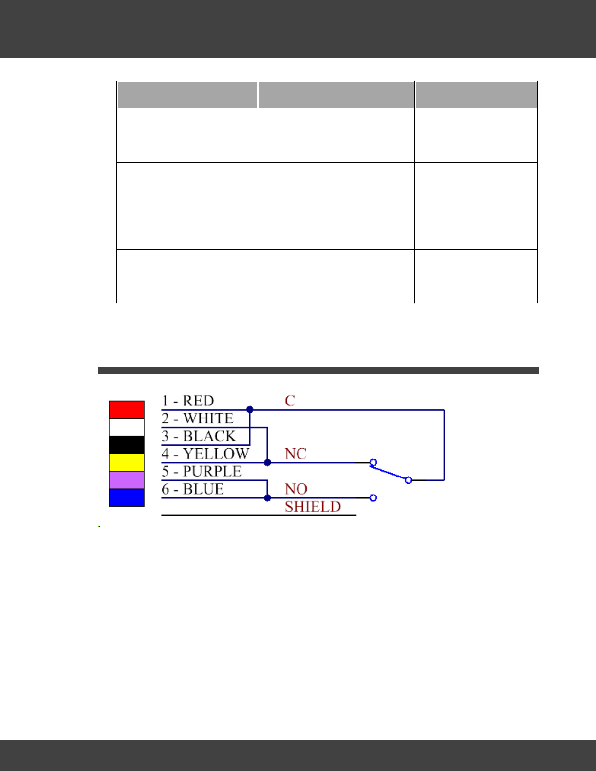
259
Notion Pro © 2017 IMC Group Ltd HP5525 Version 1.2.15
The Notion Pro Hardware
Install Step
Notes
10. Slide the appropriate
plug adaptor onto the
power supply.
Do not connect the
power supply to the
mains supply yet.
11. Plug in the Base Unit
power supply to the
mains supply and
switch on at the mains
socket.
A green light comes on.
Power Supply works
automatically with 110V-
120V or 220V-240V
mains voltage.
11. Go into Notion Pro to
add the device and
configure it for use.
See Configure Devices
6.8 Relay Connections
·Pins 1&3, 2&4, 5&6 are internally connected together in pairs to increase the current
carrying capacity
·The shield wire is internally connected to GND.
·Both relays have the same pinout and the cables are interchangeable.
·These relay outputs are suitable for low voltage switching.
Rating: Max. load1A at 24V, do NOT exceed 50V; shield is connected to Unit 0V rail.
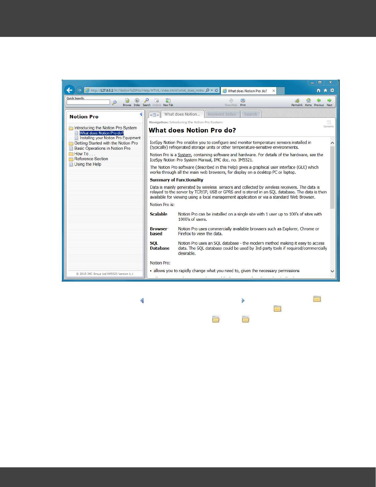
260
Notion Pro © 2017 IMC Group Ltd HP5525 Version 1.2.15
Using the Help
7Using the Help
Selecting Help>Notion Help gives the Notion Pro Help, in its own window.
The large pane on the right gives the Help for the topic you have selected in the 'contents
list' pane on the left. Click to hide the contents pane, click to show it again. The
symbols and the text alongside them are 'chapter headings'. Click the to show the
contents of the 'chapter' (the symbol changes to ), click again to hide the chapter
contents. Some of the 'headings' have their own content (for example 'Getting Started' and
'The Opening Display'), some 'headings' just open onto a list of Help topics (for example
'Basic Operations in Notion Pro').
The tabs at the top of the topic pane give you tools for getting Help in different ways.
The left-hand tab displays the name of the currently displayed Help topic. The Keyword
Index gives a list of keywords (like an index in a reference book) that you can search on
for Hep.
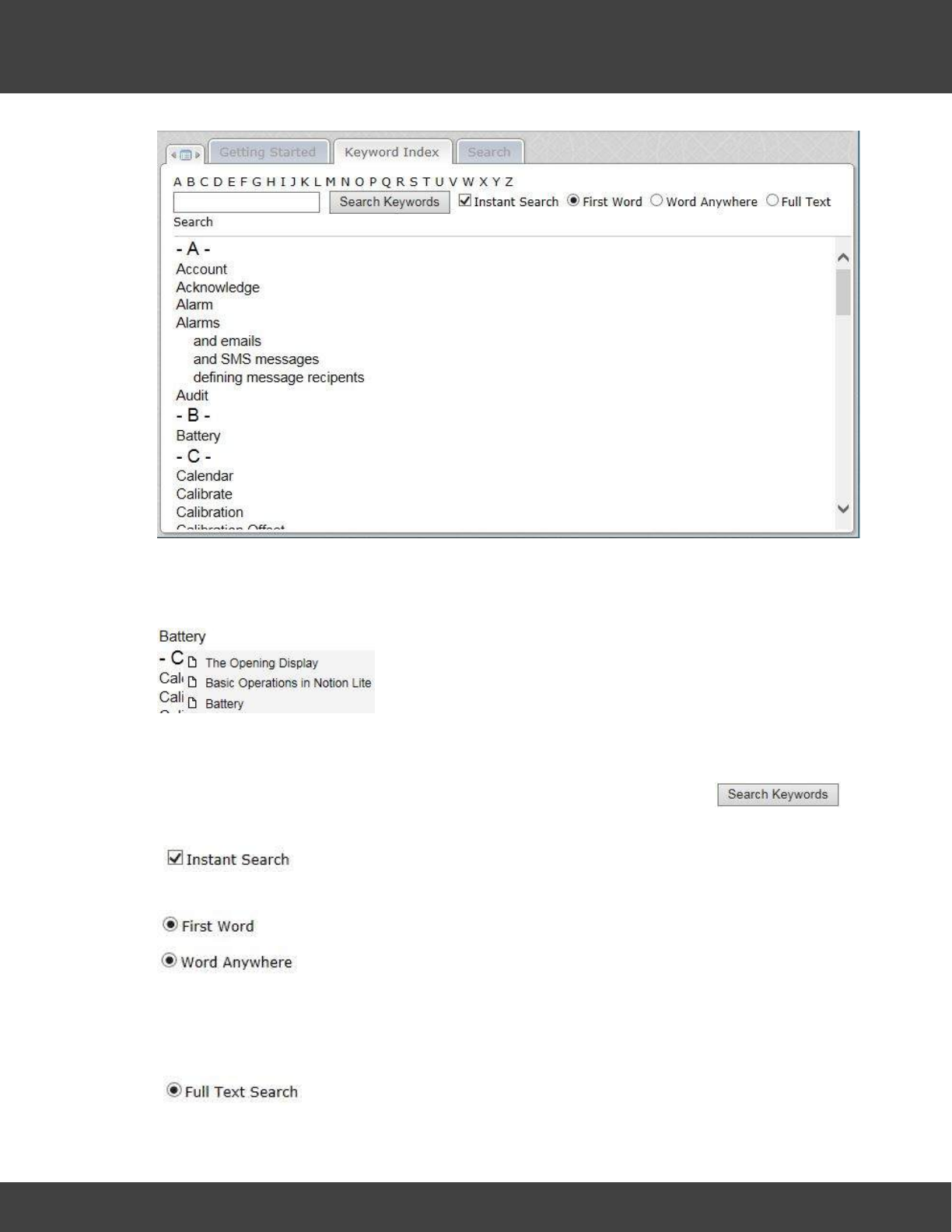
261
Notion Pro © 2017 IMC Group Ltd HP5525 Version 1.2.15
Using the Help
For example, to find a Help topic containing the word 'Calendar' simply click on Calendar in
the index on the left. Some keywords appear in more than one Help topic, and a sub-menu
of topics appears. For example, 'Battery' appears in three Help topics:
To click on another keyword move down the list using the scroll bar on the right, or click on
a keyword initial letter on the list at the top.
To search for a keyword, enter the keyword in the box to the left of the
button, then click on the button.
means that the search will jump to the required keyword, and highlight it,
even before you have finished typing it. Clear the tick box to disable this facility.
means only the keyword whose first word is the search keyword is found,
means that all keywords which contain the search keyword at any
position will be found. For example, a search for 'Offset' with 'First Word' selected means
that 'Offset' will be found but 'Calibration Offset' would not be. A search for 'Offset' with
'Word Anywhere' selected would mean that both 'Offset' and 'Calibration Offset' would be
found.
means that
any
word containing the search keyword string will be found.
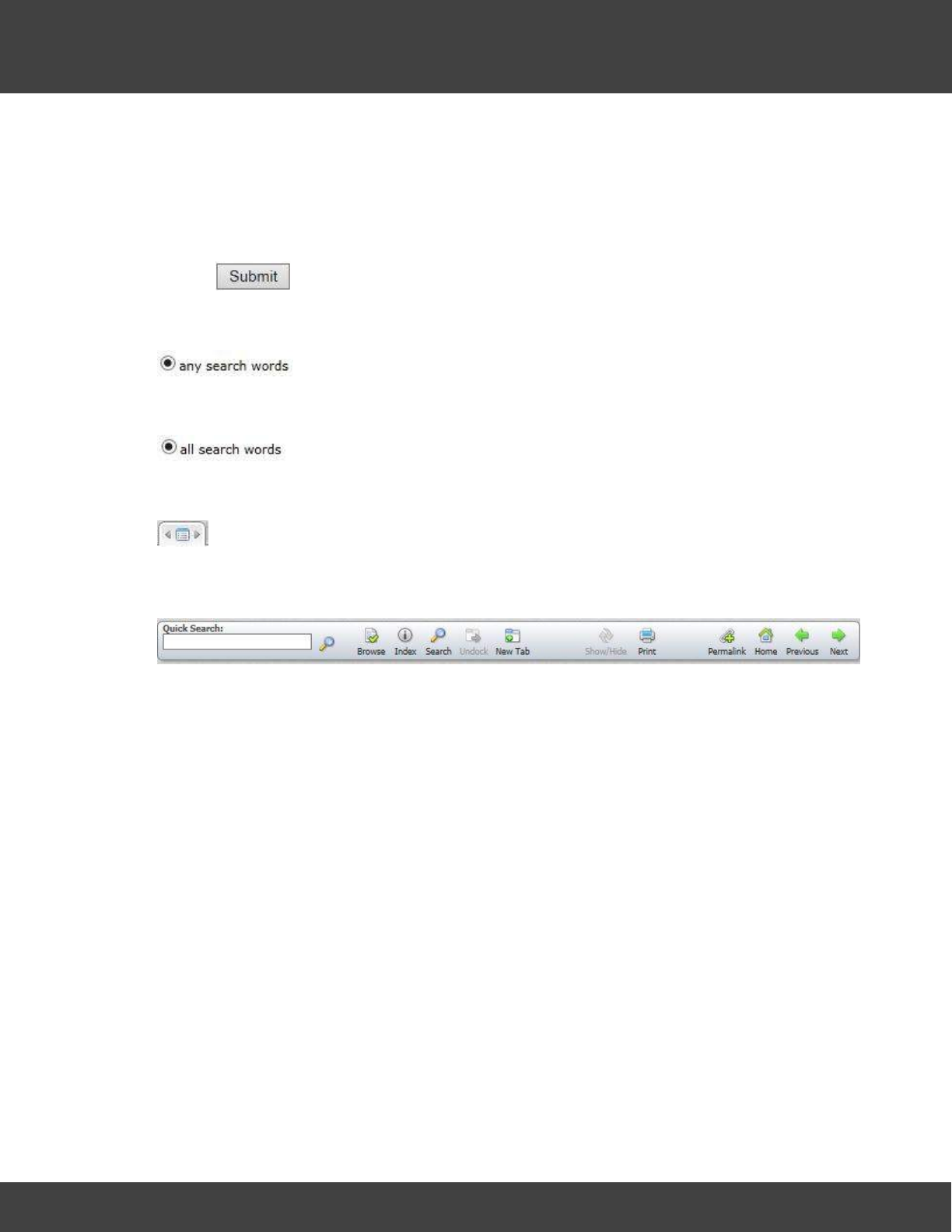
262
Notion Pro © 2017 IMC Group Ltd HP5525 Version 1.2.15
Using the Help
For example, a search for 'Cal' with 'Full Text Search' clear would find 'Calendar', 'Calibrate',
'Calibration' and 'Calibration Offset' but not 'Graphical Display'. With 'Full Text Search'
selected, 'Graphical Display' would be found too.
The Search tab enables you to search for any keyword in the Help, regardless of whether
the word is in the Keyword Index or not.
Clicking will produce a list of topics which contain the keyword(s) that has been
searched for, ranked in order of number of occurrences of the keyword within the topic.
The Score value gives the relevance of the topic found.
means that topics containing
any
of the search keywords will be listed. For
example a search for 'Configure Transmitters' would give a list of all topics containing
'Configure'
or
'Transmitters'.
means that only those topics containing
all
of the keywords will be listed.
For example a search for 'Configure Transmitters' in this case would give a list of all topics
containing 'Configure'
and
'Transmitters'.
gives a method of scrolling through the three tabs at the top of the Help window
(click the left and right arrowheads).
The Help toolbar:
gives additional methods of navigating through the Help and performing operations on it.
(Most of the icons in the toolbar perform the same operations as the main Topic/Keyword
Index/Search tabs described above.)
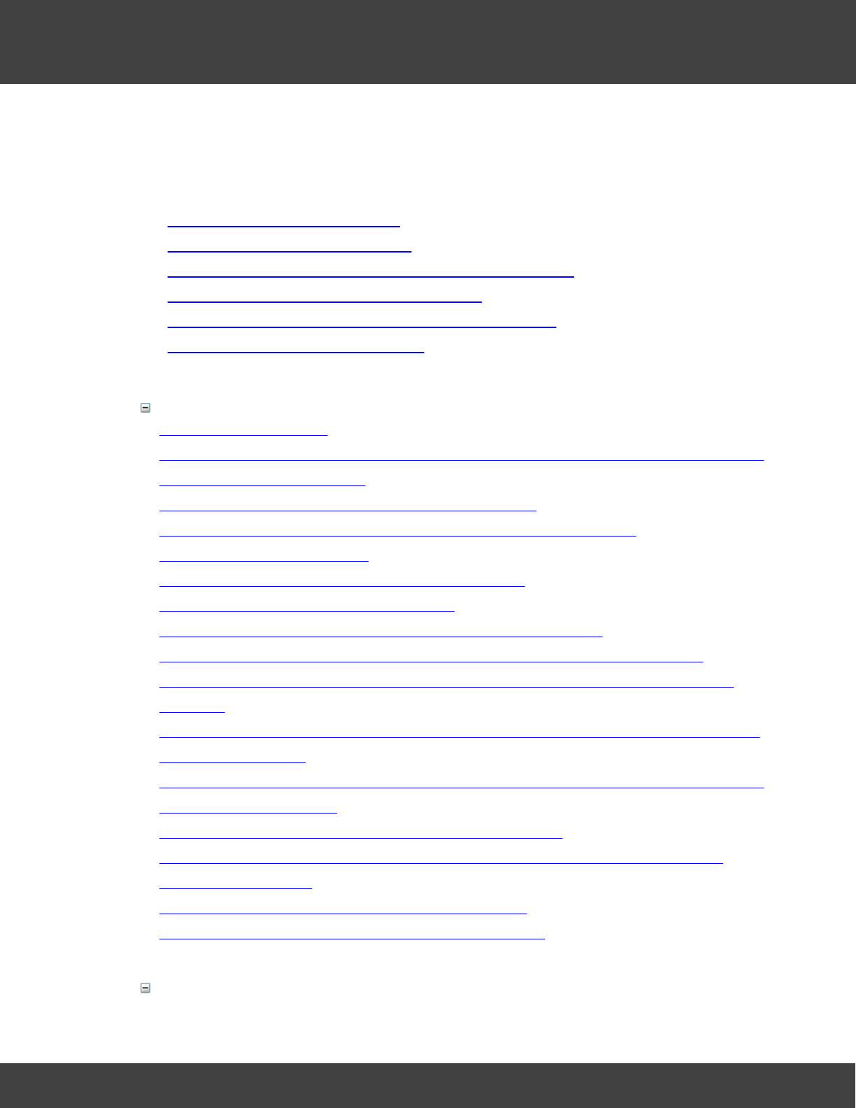
263
Notion Pro © 2017 IMC Group Ltd HP5525 Version 1.2.15
Frequently Asked Questions
8Frequently Asked Questions
FAQ Contents
Operating System Questions
Can I install Notion Pro on Windows 8?
Can I install Notion Pro on Windows 8.1?
Can I install Notion Pro on Mac, Linux, Windows XP or Server 2003?
How do I tell if my PC is Windows Pro or Enterprise?
How do I add .Net 3.5 to Server 2012 without installation media?
Do you need any Microsoft user accounts?
Licensing, Hosting & Components Questions
How is the system licensed?
What are the typical server requirements for the server side of the system? List the requirements for
physical and virtual environments?
How can the main server system software be supplied/hosted?
Does the system use any third party API’s if so are there any cost implications?
Is there any hardware limitations?
When will the system be offline and unavailable to the user?
Does the system require any third party licences?
Can the system be installed and operated in a virtual server environment?
If the system is supplied as SaaS (Software as a Service) in the cloud where is it located?
If the system is supplied as SaaS (Software as a Service) in the cloud would this hosted at your
premises?
If the system is supplied as SaaS (Software as a Service) in the cloud does it operate independently
from the other systems?
If the system is supplied as SaaS (Software as a Service) in the cloud what methods are available to
prevent unauthorised access?
Does the system have an API (Application Programming Interface)?
Does the client interface require any additional software (Plug-ins, Add-ons, Java, Flash, word
processor, spreadsheet)?
Is there a fixed schedule for software upgrades and patches?
Are there training or test environments available on the system?
Database Questions (SQL/Data Storage)
264
Notion Pro © 2017 IMC Group Ltd HP5525 Version 1.2.15
Frequently Asked Questions
What SQL server can I use with Notion Pro W600B?
Can I use Notion Pro with an Oracle SQL or a MySQL server?
When I create a New Database from NotionProConfig, I get a TargetInvocationException message?
What is the expected database growth?
Notion Pro does not work after a Microsoft SQL update?
When I browse to Notion Pro I see text with SQL login or connection errors; or the
NotionProDataService is showing SQL login or connection errors in the Application Event Log; what
can I do?
How can system data be backed up?
Can the system archive data?
Is the system scalable?
How can you retrieve a complete copy of the dataset?
If hosted system contract is terminated what happens to the data?
Are there any limits the number of concurrent users?
Is there a limit to the data volumes on the server side of the system?
What are the backup and data protection measures?
On hosted systems what are the DR and BC plans?
Will the system need to be off line during the back-up process?
Network, E-mail & Connection Questions
What is the data upload from a Network Receiver / Hybrid Receiver Base Unit to the Notion Pro
server?
Notion Pro is not working with my email server, what can I do?
How do I find the DNS suffix required for Notion Pro Base Util settings?
There is no data arriving from my Base, or my ARB Module shows no Alarm screens, what can I do?
How do I allow internet access to the Notion Pro website?
How much internet bandwidth capacity is required for users client interface?
What protocols does the system use?
What is RSSI?
Security & Conformity Questions
What is the minimum password length?
What is the Password Strength?
Where are the passwords stored?
Can users change their passwords?
265
Notion Pro © 2017 IMC Group Ltd HP5525 Version 1.2.15
Frequently Asked Questions
Can administrators change user’s passwords?
Can the system enforce a password change at initial logon?
Is a user forced to change their password after an administrator has reset it?
Can the system enforce password history?
Can the user id and password be the same?
Does the system enforce a maximum password age?
Are accounts suspended if the user fails to change their password before or at the maximum
password age?
Are passwords encrypted?
Can the system suspend an account after a number of failed login attempts?
Does the system have an inactivity logout?
Can the system control user access rights?
Does the system maintain a log of all system activity?
Are system activity logs date and time stamped?
Can you view or export the system activity logs?
Are there any security implications or restrictions arising from the use of the system in a virtualised
environment?
Does the system conform to eGov standards BS7666 for personal information?
Are there any licence implications arising from the use of the system in a virtualised environment?
Does the system conform to the Data Protection Act 1998?
Does the system have built in audit trail to track user changes?
Does the system undergo regular independent security testing by an accredited organisation with
recognised qualification CESG (Certified Cyber Security Consultancy)?
Do the Service providers that host the systems have ISO27001?
Who has access the audit trail on the system?
Is there any system testing during the system deployment?
Does the system support data classification schemes such as HMG Protective Marking Scheme?
Is there any personal data held on the system that needs to be transferred in accordance with the 8th
principle of the Data Protection Act 1998?
Is the data in transit appropriately encrypted?
Is the System compliant with UK e-Gov standard e-GIF interoperability?
User Interface & Browser Questions
Graphs are not displaying properly, and/or date time pickers not working with Internet Explorer?
Notion Pro does not display properly in my browser after an upgrade?

266
Notion Pro © 2017 IMC Group Ltd HP5525 Version 1.2.15
Frequently Asked Questions
How can the data be viewed?
On what devices can the data be viewed?
Where can I view my data if my system is on my LAN?
Where can I view my data if my system is in the Cloud?
Operating System Questions
Can I install Notion Pro on Windows 8?
There is no technical reason why Notion Pro should not work with Windows 8 Pro or
Enterprise. However; due to the limited business user base and difficulties with using the
user interface on a PC, The IMC Group does not recommend, or provide support for,
Notion Pro installations on Windows 8.
Customers should upgrade to Windows 10, before installing Notion Pro.
Can I install Notion Pro on Windows 8.1?
Synergy can be installed on Windows 8.1 Pro or Enterprise. However; due to the limited
business user base, The IMC Group is only able to provide limited support for Notion Pro
installations on Windows 8.1; and would recommend upgrading to Windows 10, before
installing Notion Pro.
Can I install Notion Pro on Mac, Linux, Windows XP or Server 2003?
No.
How do I tell if my PC is Windows Pro or Enterprise?
Note: This FAQ only applies to desktop operating systems, such as Windows 7, Windows
8.1 and Windows 10; it does not apply to server operating systems.
Open: Control Panel à System.
Below the ‘View basic information about your computer’ title, there is a section headed
‘Windows edition’.
Here you should see something like:
Windows 7 Professional, or Windows 7 Enterprise,
Windows 8.1 Pro, Windows 8.1 Enterprise,
Windows 10 Pro, Windows 10 Enterprise.
Some editions may show a letter code, such as ‘N’ at the end of the edition description, e.g.
‘Windows 10 Enterprise N’, this can be ignored.
If your edition of Windows is not shown above, then Notion Pro may not work on your

267
Notion Pro © 2017 IMC Group Ltd HP5525 Version 1.2.15
Frequently Asked Questions
computer and should not be installed.
How do I add .Net 3.5 to Server 2012 without installation media?
Note: This requires an internet connection.
Open a command prompt as administrator, and run the following command:
dism /online /enable-feature /featurename:NetFx3 /all
Check server features, .Net Framework 3.5 should be added.
Licensing, Hosting & Components Questions
How is the system licensed?
On-premise systems will need licensing by sites, users, and add-ons if you require more
than the default options.
What are the typical server requirements for the server side of the system? List
the requirements for physical and virtual environments?
See the system prerequisites documentation.
How can the main server system software be supplied/hosted?
The system can be supplied as SaaS (Software as a Service) or On-Premise.
Does the system use any third party API’s if so are there any cost implications?
Yes, but no cost implications to the end user.
Is there any hardware limitations?
See system prerequisites documentation.
When will the system be offline and unavailable to the user?
During the application system upgrades and patches and also during some applications of
Microsoft updates to the server.
Does the system require any third party licences?
Yes at no additional cost to end user: Accepted by EULA agreement.
Can the system be installed and operated in a virtual server environment?
Yes, works with standard virtualisation technologies (VMware etc.).
If the system is supplied as SaaS (Software as a Service) in the cloud where is it

268
Notion Pro © 2017 IMC Group Ltd HP5525 Version 1.2.15
Frequently Asked Questions
located?
We normally use UK data centres to host our systems but in principle anywhere.
If the system is supplied as SaaS (Software as a Service) in the cloud would this
hosted at your premises?
No to ensure customer SLA’s and security levels are maintained we outsource suppliers that
meet our requirements.
If the system is supplied as SaaS (Software as a Service) in the cloud does it
operate independently from the other systems?
Each customer system is allocated its own server environment therefore each system
operates independently by design, only sharing the underlying resources of the cloud.
If the system is supplied as SaaS (Software as a Service) in the cloud what
methods are available to prevent unauthorised access?
The system can be connected with a site to site using VPN (Virtual Private Network), and/or
use a configurable firewall.
Does the system have an API (Application Programming Interface)?
There are no direct APIs available however we do provide access to data via Modbus and
OPC at additional cost.
Does the client interface require any additional software (Plug-ins, Add-ons,
Java, Flash, word processor, spreadsheet)?
The client interface uses just standard browser technology. Viewing user generated reports
will however require a PDF reader and / or a CSV file reader.
The management tool will require software to be installed (normally on just one machine).
This tool is used for a variety of hardware related configuration tasks
Is there a fixed schedule for software upgrades and patches?
No, updates are released as required.
Are there training or test environments available on the system?
Yes easily created as required.
Database Questions (SQL/Data Storage)
What SQL server can I use with Notion Pro W600B?
Microsoft SQL 2008 R2, Microsoft SQL 2012, or Microsoft SQL 2014.

269
Notion Pro © 2017 IMC Group Ltd HP5525 Version 1.2.15
Frequently Asked Questions
Can I use Notion Pro with an Oracle SQL or a MySQL server?
No.
When I create a New Database from NotionProConfig, I get a
TargetInvocationException message?
This Exception is thrown by the underlying Microsoft .Net code when your server has
Federal Information Processing Standards (FIPS) mode enabled; Microsoft no longer
recommend the use of FIPS mode.
To disable FIPS Mode:
Control Panel à System and Security à Administrative Tools à Local Security Policy.
In Security Settings, expand Local Policies, and then click Security Options.
Scroll down to “System Cryptography: Use FIPS compliant algorithms for encryption,
hashing, and signing”. Make sure the setting is disabled.
You will now need to use Microsoft SQL Server Management Studio to delete the notionPro
database, before clicking New Database again.
What is the expected database growth?
Depends on number of sensors, Sensor types, number of alarms and logged events etc. If
we took a system with 50 sensors, (40 single channel and 10 dual channel), as an example,
the data growth would be approximately 700Mb per year + Alarms + log entries + SQL
transaction log.
When I browse to Notion Pro I see text with SQL login or connection errors; or
the NotionProDataService is showing SQL login or connection errors in the
Application Event Log; what can I do?
Note: A SQL Login error can be caused by a connection issue to the SQL server instance; it
is not necessarily an account login issue.
W600B systems:
Because W600B systems connect to a database on a different machine to the Notion Pro
server, the Apache Service and NotionProDataService run as a specified active directory
user, created by your IT Administrator or service provider so that the services can
authenticate against the SQL server.
There are a number of potential causes: not rebooting after an upgrade; network
connection issue; firewall changes; logins being changed on the domain; logins being
changed on the SQL server or a user changed on the database; that the Notion Pro or SQL
server for some reason, could not get a connection to the Customer’s domain controller on
a reboot; antivirus program blocking the connection on start-up; Notion Pro or SQL server

270
Notion Pro © 2017 IMC Group Ltd HP5525 Version 1.2.15
Frequently Asked Questions
name change; database(s) being altered; to name but a few.
Note: If you request IMC Group Ltd Support and the problem turns out to be an internal IT
issue, such as one of the above, then you may be charged for the support given.
Note: W600B systems must be installed and maintained by experienced IT personnel; as
such this FAQ answer is intended for IT Administrators, if you are not an experienced IT
professional, ask your IT Administrator or service provider for assistance. In order to fault
find this kind of problem, you will need administrator access to both the Notion Pro Server,
and the SQL Server.
If SQL Server Management Studio is installed on the Notion Pro Sever, use it to test the
connection to your SQL Server.
If SQL Server Management Studio is not installed, you can test the connection using Telnet;
Tenet to the SQL server on the instance port number, (the default port number is 1433); if
you get a connection error message, then your IT Administrator or service provider will
need to resolve the connection issue to the SQL server.
If the connection works; then you can try restarting the Apache service and the
NotionProData Service – this can resolve odd login glitches.
Next check that the Login used by Notion Pro has not been altered. During installation, the
Apache service, NotionProArchiveService, and NotionProDataService will have been set to
use a network login account provided by your network administrator. Check that the
services still log on as this account.
Check that this login still exists on the SQL server instance, and also that the user still exists
on the notionPro and IMCNotionProArchive databases:
notionPro database user should have db_datareader, db_datawriter,
db_backupoperator and db_owner roles.
IMCNotionProArchive database user should have db_datareader and db_datawriter
roles.
Check that the login password has not been altered; try to login as the user on a network
computer, or try resetting the user login on one of the Notion Pro services.
W600A systems:
There are a number of potential causes: not rebooting after an upgrade; logins being
changed on the SQL server or a user changed on the database; antivirus program blocking
the connection on start-up; Notion Pro server name change; database(s) being altered; and
others.
Note: If you request IMC Group Ltd Support and the problem turns out to be an internal IT
issue, such as one of the above, then you may be charged for the support given.
Note: In order to fault find this kind of problem, you will need to be logged onto the Notion
Pro server as a local administrator.
Run SQL Server Management Studio. The
Connect to Server
dialog will show, the
Server
Name
entry should show the name of your Notion Pro server and the SQLEXPRESS
instance, in the form <Server name>\SQLEXPRESS; if the correct entry is not shown,
select it from the drop down combo selection; click connect.

271
Notion Pro © 2017 IMC Group Ltd HP5525 Version 1.2.15
Frequently Asked Questions
If SQL Server Management Studio cannot connect to the SQL server instance, make sure
the SQL server is running. Open Control PanelàAdministrative ToolsàServices; then try
starting or restarting SQL Server (SQLEXPRESS) and SQL Server Browser.
Expand Security then Logins. Check Management, and NT AUTHORITY\NETWORK
SERVICE or Network Service, and NT AUTHORITY\SYSTEM or System Logins are present.
Expand Databasesà notionProàSecuirtyàUsers; check that the following users are
present: Management, and NT AUTHORITY\NETWORK SERVICE or Network Service, and
NT AUTHORITY\SYSTEM or System.
In turn right click each User, and select properties; check the following roles:
Network Service user must have db_datareader and db_datawriter.
System must have db_datareader, db_datawriter, db_backupoperator and
db_owner.
Expand IMCNotionProArchiveàSecuirtyàUsers; check that the NT AUTHORITY\SYSTEM
or System User has the db_datareader and db_datawriter roles.
If any of the Users, Logins, or roles is missing, they will need to be recreated; it is advisable
to request IMC or your distributor to do this work.
Note: Where IMC provides support to fix changes that have been made to Users, Logins,
and / or Roles; then this work will be chargeable.
How can system data be backed up?
The system has its own archive and backup routines, which allow data to be stored in a
convenient location, ready to be backed by any proprietary backup program.
Can the system archive data?
Yes and the archived data to can be viewed on demand via the standard browser interface.
Is the system scalable?
Yes, within SQL data limits.
How can you retrieve a complete copy of the data-set?
All of the system backups are a complete copy of the data-set.
If hosted system contract is terminated what happens to the data?
After giving the customer the option of a copy of the data, the hosted system will be rebuilt
with a fresh image and all data erased.
Are there any limits the number of concurrent users?
Only limited by SQL version and underlying system resources
Is there a limit to the data volumes on the server side of the system?

272
Notion Pro © 2017 IMC Group Ltd HP5525 Version 1.2.15
Frequently Asked Questions
Yes limited by the version of the SQL (SQL express: 10GB, SQL Standard: > 1 terabyte)
What are the backup and data protection measures?
This depends on the system configuration, design and end user requirements.
On hosted systems what are the DR and BC plans?
Hosted Systems DR and BC considerations are configured in line with individual end user
requirements. Typically DR would involve server imaging and off site data backup.
Will the system need to be off line during the back-up process?
No
Network, E-mail & Connection Questions
What is the data upload from a Network Receiver / Hybrid Receiver Base Unit to
the Notion Pro server?
This depends on the number of sensor being received by the base receiver. Trying to give
a size for one sensor would be of little value, as data is transferred from the base unit at
about the same frequency as the sensor transmission rate; so most of the data would
actually be due to the communications protocol. If we took a system with 50 sensors; then
the average upload would be approximately 7700bytes. Uploads occur approximately once
per minute.
Notion Pro is not working with my email server, what can I do?
First of all, check the Notion Pro Email log for error messages. And make sure that you
have entered the email server name / IP address; sender email address; and user name
and password correctly.
When you are sure all the settings are correct; then you can try to connect to the email
server from the Notion Pro server using the Windows Telnet client.
Note: you may need to turn on the Telnet Client in Windows features first.
Open a command prompt, and type Telnet <email server host name or IP address>:<port
number> <press enter>
For example: mailserver:465 or 192.168.1.12:25
You should see a login message from your email server - the exact message will depend on
the email server.
If you do not see a login message, then the email sever address is either wrong, or is not
reachable from the Notion Pro server; and you will need to ask your network administrator
or IT service provider for assistance.
If you get a login message, then it is most likely that the email server is refusing to accept
the account login credentials provided to Notion Pro.

273
Notion Pro © 2017 IMC Group Ltd HP5525 Version 1.2.15
Frequently Asked Questions
Check the Notion Pro server machine event log for errors. Open: Control Panel à
Administrative Tools à Event Viewer.
The select Windows Logs and then Application; look for Error entries with
NotionProDataService as the Source, and Event ID’s in the 33000, and 21000 ranges, e.g.
21007.
Looking at the General descriptions for these errors can give an indication of the problem.
How do I find the DNS suffix required for IMC Base Utility settings?
Open a command prompt on the Notion Pro server, or other Windows PC on the same
domain, and run wmic computersystem get domain
There is no data arriving from my Base, or my ARB Module shows no Alarm
screens, what can I do?
There are a number of potential causes for this problem, please work through the list below,
before contacting your supplier for assistance.
Power
Have you fitted batteries to your transmitters? If not fit them now.
If the green power LED is off, then the device is not powered, you need to connect power
to the device.
Radio Reception
For a Base check that radio data is being received. The green LED should flash periodically;
if not move a transmitter close to the base and check again; if there is still no flashing,
contact your supplier.
Network connection
The amber network LED will flash more than once a second, if a device has no network
connection, or if a DHPC enabled device is unable to obtain an IP address. If this is the case
carry out the following:
Look at the LED’s on the network socket; the amber LED should be solid, and the green LED
flashing frequently; if not you have an issue with your network connection, contact your
system administrator or IT support provider for assistance.
If the device needs to use a fixed IP:
Use the IMCBaseUtility application to re-apply settings to the device, checking that the
correct IP address is used.
If the device needs to use DHCP:
Use the IMCBaseUtiityl application to re-apply settings to the device, checking that the ‘Use
static IP Address’ check box is NOT selected.
Also, check with your system administrator or IT support provider that the DHCP server is
configured to allow your devices to obtain an address; options such MAC filtering can

274
Notion Pro © 2017 IMC Group Ltd HP5525 Version 1.2.15
Frequently Asked Questions
prevent devices from obtaining IP settings from your DHCP server.
Device Configuration
Check that the device is correctly set-up in Notion pro:
Log into Notion Pro; and select AdminàDevice ConfigurationàEdit/View Devices, this will
display a table of Control Devices.
Check that the devices serial number is correct, and for a Base check that the device is a
member of a Device Group.
Network Configuration
The amber network LED will flash approximately once a second, if the device has network
connectivity, but is unable to connect to the Data Service on the Notion Pro server. If this is
the case carry out the following:
Make sure the data service is running. On the Notion Pro server, open Control
PanelàAdministrative ToolsàServices; check that the NotionProDataService is running.
If the device is configured to connect to your Notion Pro server using a hostname, make
sure that the hostname is resolvable:
Open a Command prompt, and type nslookup <full hostname with DNS suffix> <press
enter>
Example nslookup computer.domain.local
The command will display the name and IP address of your DNS server, followed by name
and IP address of the supplied hostname. If the DNS server name and address is followed
by an error message, such as *** <DNS server> can’t find <hostname> then the
hostname you have used is not resolvable and you will need to obtain assistance from your
system administrator or IT support provider.
Make sure that any firewall on the Notion Pro server – including the Windows firewall - is not
blocking the incoming device connection; and that you have added rules to allow incoming
connections on the Base Data port, (default port number is 10997).
Make sure any Anti-Virus or network security product on the Notion pro server is configured
it to allow the various Notion pro services to operate; if the Anti-Virus / network security
product is intended for the home / consumer market, you may need to replace it with a
product intended for professional use. Contact your system administrator, IT support
provider, or the product vendor, for assistance.
How do I allow internet access to the Notion Pro website?
You will need to create a rule on your Corporate Firewall to allow an inbound connection to
your Notion Pro server on port 80.
If you wish to use a port other than 80 for external access to the Notion Pro website, you
can configure the rule to use 'Port Translation', so that the external port xxxxx is connected
to port 80 on the Notion Pro server.
Example

275
Notion Pro © 2017 IMC Group Ltd HP5525 Version 1.2.15
Frequently Asked Questions
Internal users - http://LAN-Address/notionpro
External users - http://WAN-Address/notionpro
External users with Port Translation' - http://WAN-Address:xxxx/notionpro
Note: Different Firewalls use different terminology. 'Port Translation' may be called some
thing different on your Firewall.
How much internet bandwidth capacity is required for users client interface?
Several client users can be connected over a standard ADSL line.
What protocols does the system use?
SMTP, IMAP, POP3, SMS, GPRS, HTTP client access, TCP communication between
sensors, bases, and backend system services.
What is RSSI?
RSSI stands for Received Signal Strength Indicator; it is an indication of the power in a signal
received by a radio receiver.
Security & Conformity Questions
What is the minimum password length?
It is configurable from 4 to 40 by the system administrator
What is the Password Strength?
The system can configure password strength rules by specifying the minimum number of
upper case letters, lower case letters, and numbers. Options are set by the system
administrator.
Where are the passwords stored?
They are stored as non-readable encrypted strings in the SQL database
Can users change their passwords?
Yes as long as they know their old password.
Can administrators change user’s passwords?
Yes they can without knowing the old password. A counter signatory will be required for this
in the compliant versions.
Can the system enforce a password change at initial logon?
Yes but currently only on compliant systems

276
Notion Pro © 2017 IMC Group Ltd HP5525 Version 1.2.15
Frequently Asked Questions
Is a user forced to change their password after an administrator has reset it?
Yes but currently only on compliant systems.
Can the system enforce password history?
Yes the password depth is set to 1 in the standard system, and is configurable up to a
maximum of 10 on a compliant system. Specifying a low number for ‘Enforce Password
History’ allows users to continually use the same small number of passwords repeatedly
Can the user id and password be the same?
No, the system will not allow the user to use a password the same as their ID.
Does the system enforce a maximum password age?
Yes, it is configurable by system administrator from 30 to 730 days.
Are accounts suspended if the user fails to change their password before or at
the maximum password age?
The account is not actually suspended, but the system will not allow further access until the
user has changed their password.
Are passwords encrypted?
Yes
Can the system suspend an account after a number of failed login attempts?
Yes, if the user exceeds the number of allowed retries (can be set 1 to 10) in the
predefined retry period of time (can be set from 10 to 1140 minutes). The user will be
locked out of the system for predefined period of time (up to 1140 minutes).
Does the system have an inactivity logout?
Yes the time period can be set from 5 to 60 minutes.
Can the system control user access rights?
Yes individually, or by assigning them to groups/roles.
Do you need any Microsoft user accounts?
Only on B variant systems, for the system to access the SQL database; but not for the
users.
Does the system maintain a log of all system activity?
User logins, system settings edits, alarms, and system events are logged.
Are system activity logs date and time stamped?
Yes

277
Notion Pro © 2017 IMC Group Ltd HP5525 Version 1.2.15
Frequently Asked Questions
Can you view or export the system activity logs?
Yes, you can view directly in the system and/or generate reports.
Are there any security implications or restrictions arising from the use of the
system in a virtualised environment?
No
Does the system conform to eGov standards BS7666 for personal information?
N/A - There is no personal information held on the system.
Are there any licence implications arising from the use of the system in a
virtualised environment?
No
Does the system conform to the Data Protection Act 1998?
The system does not hold any client information that is subject to the Data Protection Act
1998.
Does the system have built in audit trail to track user changes?
Yes user changes are logged along with date/time, but not the IP address of the user.
Does the system undergo regular independent security testing by an accredited
organisation with recognised qualification CESG (Certified Cyber Security
Consultancy)?
No
Do the Service providers that host the systems have ISO27001?
Yes
Who has access the audit trail on the system?
Access to the audit trail is set by the administrator and defined on an individual basis or by
roles in the system.
Is there any system testing during the system deployment?
Yes, if the compliant option is selected
Does the system support data classification schemes such as HMG Protective
Marking Scheme?
No.

278
Notion Pro © 2017 IMC Group Ltd HP5525 Version 1.2.15
Frequently Asked Questions
Is there any personal data held on the system that needs to be transferred in
accordance with the 8 th principle of the Data Protection Act 1998?
No the system does not hold any personal data.
Is the data in transit appropriately encrypted?
Not in HTTP version of the product but HTTPS can be supported.
Is the System compliant with UK e-Gov standard e-GIF interoperability?
The system conforms to some of the key e-GIF policies, by adoption of the browser as the
key interface presenting data and adoption of common specifications used on the Internet
and World Wide Web for public sector information systems.
User Interface & Browser Questions
How can the data be viewed?
The client access is by a web browser (for a full up-to date list of compatible web browsers
please contact IMC technical support)
On what devices can the data be viewed?
The target client is PC’s and Laptops, it can be viewed on mobile devices (but it is not
optimised for these).
Where can I view my data if my system is on my LAN?
Only via machines on your LAN, unless your firewall is configure to provide the system with
a connection from WAN.
Where can I view my data if my system is in the Cloud?
From any location with internet access. This may be limited to devices on a VPN if you have
selected that hosting option.
Graphs are not displaying properly, and/or date time pickers not working with
Internet Explorer?
This problem is usually due to
Compatibility Mode
being enabled; go to Tools -->
Compatibility View Settings, and disable
Display intranet sites in Compatibility View
.
Notion Pro does not work after a Microsoft SQL update?
Some SQL updates can leave the SQL server restricted to
Single User access; in this case
,
rebooting the SQL server will usually correct the problem.
Notion Pro does not display properly in my browser after an upgrade?

279
Notion Pro © 2017 IMC Group Ltd HP5525 Version 1.2.15
Frequently Asked Questions
Browser improve web page load times, by caching recent / frequently used pages; cached
pages can cause Notion Pro to appear corrupted after an upgrade; to fix this issue, clear
your browsers cache or history.
The actions required to clear cache / history cannot be laid out in this FAQ because they
differ between browsers, and even between different versions of the same browser;
however, a quick internet search will usually provide the required information.

280
Notion Pro © 2017 IMC Group Ltd HP5525 Version 1.2.15
Warnings FCC
9Warnings FCC
FCC Class A Notice
Devices sold into the USA comply with Part 15 of the FCC Rules. Operation is subject to the
following two conditions:
1. This device may not cause harmful interference.
2. This device must accept any interference received, including interference that may cause
undesired operation.
Note: This equipment has been tested and found to comply with the limits for a Class A
digital device, pursuant to Part 15 of the FCC Rules. These limits are designed to provide
reasonable protection against harmful interference when the equipment is operated in a
commercial environment. This equipment generates, uses, and can radiate radio frequency
energy, and if it is not installed and used in accordance with the instruction manual, it may
cause harmful interference to radio communications. Operation of this equipment in a
residential area is likely to cause harmful interference, in which case the user will be required
to correct the interference at his own expense.
Modifications: Any modifications made to this device that are not approved by The IMC
Group Ltd may void the authority granted to the user by the FCC to operate this
equipment.

281
Notion Pro © 2017 IMC Group Ltd HP5525 Version 1.2.15
Index
- A -
Acceptable conditions 197
Account Settings 66
Acknowledge 225
Al a rm
acknowledging 17, 57, 225
active days 146
advance 43, 146
delay 17, 43, 57, 225
disable 146
enable 146
filters 43, 146
high level 146
high range 146
interference 43
levels 17, 43, 57, 146, 225
setting notes against 138
status tooltip 192
Alarm Management 195
Al a rms
digital 146
global 146
location 195
Alert Group 106
Audi t
displaying 17
Auto Logout 66
- B -
Base Station 8
connectors 228
Ba ttery
viewing charge state of 16, 17, 226
- C -
Calendar 43
Calibration 43
Calibration Technician 66
Can I install Notion Pro on Mac, Linux, Windows XP or
Server 2003 263
Can I install Notion Pro on Windows 8 263
Can I install Notion Pro on Windows 8.1 263
Can I use Notion Pro with an Oracle SQL or a MySQL
server 263
Communication status 49
Communi c ati ons
status 195
Compliance 231
Configure 16
Connectors
base station 228
Contacts 66
Control device 121
Current clamp 43
Cur s or
use of within graphical view 167
- D -
Da ta
live 16, 17, 227
Database logger 41, 121
Default View 188
Device Group 41
Device Groups 121
Device Sensor Lists 121
Door 43
closed 16, 17, 226
open 226
sensor 146
time open 16, 17, 226
- E -
Edit Mode 43, 146
Email 21
Email Server 211
External Contacts 24
- F -
Fa ls e Al arms
preventing 146
- G -
Global Settings 146, 189
GPRS 8
Gra phi ca l di s pl ay

282
Notion Pro © 2017 IMC Group Ltd HP5525 Version 1.2.15
Index
Gra phi ca l di s pl ay
previous 167
reset 167
zooming in 167
Group
device 121
- H -
Ha rdware
setting up 9
Hel p
how to use 260
How do I add .Net 3.5 to Server 2012 without installation
media 263
How do I allow internet access to the website 263
How do I find the DNS suffix required for Notion Pro Base
Util settings 263
How do I tell if my PC is Windows Pro or Enterprise 263
Humi di ty
relative 227
- I -
I cons
live view 192
- L -
Last Reading 17, 227
LED Operation 248
Level Alarm 167
Li ghts
base station 229
Listening port 121
Live Data 227
viewing 192
Li ve Vi ew
controls and indicators 192
Lockout 66
Logs
activity 61, 217, 218
alarm 61, 217, 220
email 61, 217, 221
SMS 61, 217, 221
system 61, 217
- M -
Manuals 228
Mes s a ge
system 57, 195
- N -
Network 9
Next 167
Notion Pro is not working with my email server, what can
I do 263
- O -
Overlay sensors 167
- P -
Password 21, 23, 66
Permi s s i ons
user 30, 82, 228
Phone number 21
Privileges 21
- R -
Range Alarm 167
Reactivate 197
Receiver 8
connectors 229
lights 229
Report 17
calibration 205
exception 207
scheduled 211
summary 201
Reports
creating 58
viewing 16
RFID 249
Role 21
Rol e defi ni ti ons
recommended 82
Roles 30

283
Notion Pro © 2017 IMC Group Ltd HP5525 Version 1.2.15
Index
Roles 30
suggested definitions 229
Round Robin 106
- S -
Sca l e
of graph 167
Security 66
Sensor 146
Sens or da ta
from a different time span 54, 55
from the past 54
Sens or Groups
additional licences 158, 161
creating 158
viewing 161
Sensor LED 248
Sens or va l ues
units 190
Sensors 8
adding 43, 138
alarms 43, 142
calibration 43
calibration scale 142
channels 146
configuring 43, 138, 142
copying 138
deleting 138
door 146
filters 43, 142
general settings 43, 142
listing 121
location 142
Service Ports 41
Setti ngs
global 189
low level 146
low range 146
rate of change 146
setting notes against 146
Si gnal s trength
maximising 248
Signing In 17
Site 48, 117
choosing 166
Sites 39
Deleting 26
Editing 26
SMS 21
SMS Alerts 38
SMS Times 106
SQL 8
Status 16, 17
Sub Site 117
Sub Sites 39
Sub-Site 48
Subsites 26
System Logs 61
System Message 49, 57
System Messages 195
System Overview 17
- T -
TCP/IP 8
Tempera ture da ta
viewing 51
There is no data arriving from my Base, or my ARB
Module shows no Alarm screens, what can I do 263
Threshold 227
General 225
Time out 197
Timed Reset Override 197
transmitter LED 248
Transmitters 8
installing 223
removing 223
replacing 223
re-using 223
setting up in Notion Lite 223
swapping 223
- U -
USB 8
User Group 25
Users 66
assigning privileges to 16, 21
creating and editing 16, 21
listing 21
- V -
Viewing Rights 48

284
Notion Pro © 2017 IMC Group Ltd HP5525 Version 1.2.15
Index
- W -
What is the data upload from a Network Receiver /
Hybrid Receiver Base Unit to the Notion Pro server 263
What is the expected database growth 263
What SQL server can I use with Notion Pro W600B 263
When I browse to Notion Pro I see text with SQL login or
connection errors; or the NotionProDataService is
showing SQL login or connection errors in the
Application Event Log; what can I do? 263
When I create a New Database from NotionProConfig, I
get a TargetInvocationException message 263
- Z -
Zones
changing display to 53, 192
creating 29
deleting 135, 137, 138
editing 135, 137